Article

Design and Research of Thermoelectric Generator Simulation System for Boiler Flue Gas Waste Heat

1
Faculty of Innovation Engineering, Macau University of Science and Technology, Macau 999078, China
2
School of Mechanical and Electrical Engineering, Guangdong University of Petrochemical Technology, Maoming 525000, China
3
School of Computer Science, Guangdong University of Education, Guangzhou 510010, China
*
Author to whom correspondence should be addressed.
Appl. Sci. 2023, 13(9), 5673; https://doi.org/10.3390/app13095673
Submission received: 31 March 2023 / Revised: 30 April 2023 / Accepted: 1 May 2023 / Published: 4 May 2023
(This article belongs to the Section Mechanical Engineering)

Abstract

:
One of the significant factors contributing to high energy consumption is the unutilized waste heat from flue gas in industrial boilers. Thermoelectric generator (TEG) technology can directly convert thermal energy into electrical energy, and has been gradually applied in the field of waste heat recovery due to its simple and reliable structure, environmental protection, and other advantages. In this paper, a thermoelectric generator simulation system of boiler flue gas waste heat is proposed. The experimental platform is designed by simulating the flue gas waste heat temperature condition of boiler, and the structure of cold end module and hot end module is optimized. During the experiment, the fixed temperature difference was set at 120 °C (hot end:150 °C~cold end: 30 °C). An analysis is conducted on the volt-ampere characteristics and output power of the TEG module. The output characteristics of the TEG system are analyzed under the conditions of variable load, constant load, different pump speed, different heat dissipation modes, and series and parallel connection method. The results show that the experimental platform can instantaneously and accurately test the output parameters of the TEG system, and ensure the intended design requirements. When the ratio of the load resistance to the internal resistance of the TEG module is approximately 1–1.15, the output power of the system reaches its maximum. In order to optimize the output power of the TEG system, a power prediction-based adaptive variable step size maximum power point tracking (MPPT) algorithm is introduced. Additionally, a corresponding mathematical model is formulated. Simulations demonstrate that the time of the improved algorithm to reach the stable maximum power point is 1.54 s faster than that of the traditional algorithm. The improved MPPT algorithm satisfies the criteria for speed and accuracy, diminishes superfluous energy waste, and enhances the overall system efficiency. The research results have certain guiding significance for the design and application of subsequent TEG system.

1. Introduction

Coal is the main source of power consumption in China, and the power generation efficiency is generally around 40%. According to statistics, the boiler exhaust heat loss accounts for the largest proportion of various losses in power generation. The boiler exhaust temperature is mainly concentrated in 120–150 °C, and a large amount of flue gas waste heat has not been effectively used, resulting in significant energy loss. Reducing exhaust heat loss has become a new direction of energy saving in power station boiler system. Thermoelectric generator (TEG) is a kind of power generation method that converts thermal energy directly into electricity by utilizing the Seebeck effect of thermoelectric materials [1]. When there is a temperature difference between the two ends of the thermoelectric plate, thermal energy can be directly converted into electrical energy and output. As a green power generation method, TEG has the advantages of simple structure, durability, no vibration, no noise, no pollution, and high reliability [2]. In recent years, with the development of new high-performance thermoelectric materials and reliable thermoelectric generators [3], the level of research on TEG technology has gradually improved. TEG technology will exert its advantages in the utilization of low-grade energy, such as industrial waste heat power generation, automobile exhaust waste heat power generation, solar energy and geothermal energy, etc. The research on the TEG technology of boiler flue gas waste heat plays an important role in saving energy, reducing consumption and improving the economy of power station.
Currently, research of TEG technology mainly focuses on the manufacture of high-performance thermoelectric materials, the utilization of low-grade waste heat, the simulation analysis and optimization of TEG model, and the maximum power tracking technology [4,5,6,7]. Maneewan et al. [8] put steel plates on the roof to absorb solar energy and generate temperature difference with the natural environment, so as to achieve the purpose of generating electric energy. Konstantinou et al. [9] designed a thermoelectric device that use an optimized radiator to recover energy from the exhaust gas of a marine internal combustion engine. Attar [10] designed a thermoelectric device to recover waste heat from residential steam compression refrigeration system. The results showed that TEG has a good application prospect for recovery of waste heat. Barma et al. [11] recovered the waste heat generated by the biomass hot oil heater by installing a TEG device between the industrial flue and the thermal oil pipe. Luo Yang et al. [12] established a three-dimensional model of piecewise TEG performance analysis, and appropriately optimized its geometric parameters to improve the efficiency of the system. Jia Yuan et al. [13] demonstrated the potential applicability of using flexible thermoelectric generators to recover heat from microleds. Chen Leisheng et al. [14] designed a tubular thermoelectric generator for automobile exhaust waste heat recovery. The optimal parameters of maximum open circuit voltage and power density are determined by numerical simulation. Yin Tao et al. [15] explained the influence of multi-parameter uncertainty on TEG performance from the aspects of temperature-related material performance, electric heating condition, structure and geometric size, and establish a new balanced impedance matching model for the first time. Assareh et al. [16] applied TEG technology to an integrated energy system for collecting solar energy and geothermal energy, and used the TEG module to replace the condenser in the system. The results showed that the design can effectively reduce the total cost of the system. Brazdil et al. [17] designed a small boiler waste heat recovery device to study the performance of TEG under different operating conditions, and the boiler obtained auxiliary power. Shittu et al. [18] used COMSOL software to study the multiple physical fields of a photovoltaic-thermoelectric hybrid system and to determine the optimal geometry of the thermoelectric element. Montecucco et al. [19] used the minimum breaking load to obtain the open-circuit voltage of the TEG module, which can achieve a tracking efficiency of 93%. Fauzan et al. [20] found that when TEG modules were applied to large area of heat sources, and there was always the problem of uneven temperature distribution at the hot end, which reduced the overall power output of the system. Cozara et al. [21] used GT-SUITE software to conduct numerical modeling to study the thermoelectric effect, and found that the generation power of thermoelectric modules with mixed series-parallel connection was greater than that generated by a single series or parallel connection. Aranguren et al. [22] built a calculation model for circular chimneys, and the predicted power generation accuracy of this model is 12%. Beltran-Pitarch et al. [23] proposed a method for measuring contact thermal resistance at low temperature. Khalil et al. [24] optimized the structure of industrial smoke exhaust pipes by changing the inclination Angle, and found that the output power could be increased by 5% when the inclination Angle was 15 degrees.
Previous reports mainly focused on the application of TEG technology, structural parameters optimization of TEG model, MPPT control, etc. Most of their applications belong to the recovery of waste heat at medium and high temperatures (above 200 °C), which is relatively easy to recover. For low temperature heat source (below 200 °C), the energy utilization efficiency is also lower due to its lower energy quality. Due to the limitation of production cost and conversion efficiency, there are no reliable products for large-scale commercial application, and the recycling technology is not yet mature. The exhaust gas temperature of power station boilers is mainly concentrated between 120–150 °C, which belongs to the range of low-grade waste heat.
At present, there are few researches on the application of TEG technology to low-grade waste heat of power boiler flue gas. Moreover, the detailed matching relationship between external load resistance and internal resistance of TEG module is rarely reported when the TEG system generates maximum output power under the condition of low grade waste heat. In this paper, a semiconductor TEG simulation system is designed to convert waste heat from industrial boiler flue gas into electric energy. On the basis of optimizing the structure of TEG module, the relationship between the load resistance and the internal resistance of the module is studied when the maximum power is generated by the boiler flue gas waste heat TEG system. An improved maximum power point tracking (MPPT) algorithm is proposed to reduce the energy loss of the system. The system can also indirectly output domestic hot water to reduce fuel costs. Therefore, it can improve energy efficiency and has high economic benefits. The research can provide technical reference for the application of TEG technology in the field of low-grade energy recovery.

2. Design of TEG Simulation System

2.1. Working Principle of TEG

In 1821, the German scientist Seebeck discovered during his research that when two different conductor materials form a closed loop and there is a temperature difference between the two contact points of the loop, a electromotive force will be generated in the loop. This phenomenon is called the Seebeck effect, and TEG is based on the Seebeck effect to directly convert heat into electricity [25,26].
As shown in Figure 1, A and B represent different conductor materials, and T h and T c represent the temperature at the junction of two materials. Due to the considerably greater Seebeck effect of semiconductors in comparison to metallic conductors, semiconductor material is commonly utilized in the construction of thermoelectric plates.
In light of the modest amount of electromotive force produced by a solitary TEG plate, it is customary to join several TEG plates in series or parallel configuration to create a TEG module. The TEG module itself has internal resistance, so its equivalent circuit can be represented by a voltage source and equivalent resistance, as shown in Figure 2. V O C is the open circuit voltage of the TEG module, RTEG is the internal equivalent resistance of the TEG module, and RL is the equivalent load resistance.
In Figure 2, V O C can be expressed as shown in Equation (1).
V O C = S pn ( T h T c )
S pn is the Seebeck coefficient, T h and T c are the temperatures of the hot end and the cold end respectively. The relationship between load voltage V L and open circuit voltage V O C is shown in formula (2)
V L = V O C I R T E G = S p n Δ T I R T E G
In Equation (2), I is the output current of the TEG module. The load voltage V L can be expressed as:
V L = I R L
I = S p n Δ T R L + R T E G
The output power of the TEG module can be expressed as:
P T E G = V L I = I 2 R L
Substituting Equations (4) into (5), we can get the following results:
P T E G = ( S pn Δ T ) 2 R L ( R L + R T E G ) 2
According to formula (6), when the load resistance is equal to the equivalent resistance of the TEG module, the output power of the TEG module reaches the maximum value:
P T E G = ( S pn Δ T ) 2 4 R T E G

2.2. Overall Design of TEG System

The direct disposal of low-grade flue gas waste heat is one of the main reasons for high energy consumption. Flue gas heat loss is one of the largest heat loss in power station boilers, accounting for 80% or more of the total heat loss of boilers. The most important factor affecting the heat loss of flue gas is the boiler exhaust temperature, which is generally maintained at 110 °C~150 °C [27]. Therefore, the waste heat of boiler flue gas mostly belongs to low-temperature waste heat, and the use of TEG technology will have better commercial competitiveness.
The TEG system designed in the paper is composed of TEG module, hot end module for heat exchange of boiler flue gas waste heat, cold end module, detection circuit, MPPT controller, PWM controller, DC-DC converter, battery, insulated water tank, etc. It is shown in Figure 3.
The TEG module is composed of multiple semiconductor thermoelectric plates in series or parallel, which can be encapsulated electronically in industrial applications. The function of the TEG system is to convert waste heat of boiler flue gas into electric energy. The expelled flue gas from the boiler is directed into a purpose-built pipe located at the hot end module. The pipe incorporates a spoiler mechanism to ensure that the waste heat temperature of the flue gas is evenly distributed around the pipe. Multiple thermoelectric plates can be arranged around the pipe and connected in series or in parallel to increase the output power. At the same time, tap water is heated by the TEG module, and then enters the special water tank to meet the demand for production of domestic hot water.
The working process of the system is as follows: The TEG module converts the waste heat energy of boiler flue gas into electric energy, and the output voltage and current are measured and converted into digital signals. Then, it is sent to MPPT and PWM controller to generate PWM pulse signal to control DC-DC converter. The voltage is adjusted and the maximum power output is achieved. The output energy can be used for normal operation of DC or AC load, and the function of the battery is to store energy.

3. Experimental Research on TEG Simulation System

3.1. Construction of Experimental Platform

Limited by laboratory conditions, this paper uses high-temperature heat conducting oil as heating medium to obtain a heating temperature similar to the waste heat of boiler flue gas (heating temperature between 110 °C and 150 °C), and simulates the waste heat of boiler flue gas for experimental research.
The TEG experiment device designed in the paper is shown in Figure 4. The platform is composed of five parts: TEG module, cold end module, hot end module, DC-DC module, load or battery.
(1)
Design of cold end module
In order to maintain a stable temperature difference, it is necessary to dissipate heat from the cold end in time. There are three heat dissipation modes for the cold end module: fan heat dissipation, natural air heat dissipation, and water cooling heat dissipation.
The fan heat dissipation method is to connect a heat dissipation plate with many sides on the aluminum alloy deflector, and then take away the heat conducted to the heat dissipation plate through the fan. The cooling effect is related to the area, the gap between plates and the wind speed. The natural air cooling method requires no other equipment and uses aluminum alloy deflector at the cold end to dissipate heat. Due to the relatively small thermal conductivity of air and thermal radiation, the heat dissipation method is less effective. With the extension of time, the temperature of the cold end will rise quickly and affect the efficiency. Water cooling heat dissipation is to connect the tap water into the aluminum alloy deflector, and the tap water flows in from one end of the aluminum deflector and then out from the other. This cooling method can keep the water temperature relatively stable and does not pollute the water. The output hot water can be used for industrial or domestic water.
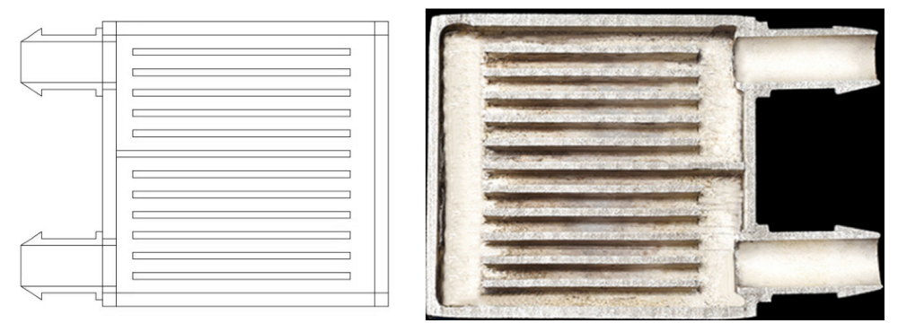
Typical water cooling heat dissipation deflectors employ a relatively slender hollow design, featuring an inlet and outlet for water at opposite ends, resulting in a suboptimal heat transfer efficiency. In this paper, the structure of the aluminum alloy deflector is optimized, and the optimized design of the aluminum alloy deflector is shown in Figure 5. The fins inside the deflector are dense, and the heat exchange effect is very good, which can ensure the uniformity of temperature on the deflector. The surface of the deflector is very smooth and has almost zero contact with the thermoelectric plate. The deflector’s inlet and outlet are outfitted with chamfered steps that facilitate installation and prevent the water pipe from detaching after being tightened.
Through the analysis of the above three cooling methods, water cooling heat dissipation method is the best, and natural air heat dissipation method is the worst. This paper intends to choose a water cooling heat dissipation method with tap water in the aluminum deflector, and the output hot water can also be used twice to improve energy utilization efficiency.
(2)
Design of hot end module
As shown in Figure 6, the hot end module is composed of aluminum alloy deflector, PT100 thermocouple, Delici relay, industrial electric heating rod, temperature sensor (Micco sensor), heat resistant silicone tube, peristaltic pump and oil tank, etc. In order to ensure the uniformity of temperature distribution at the hot end, the hot end aluminum deflector adopts the same internal structure as the water cooling deflector. The fins inside the deflector are dense, which can improve the heat exchange effect. The use of double-headed peristaltic pumps solves the problem of hot oil and water flow.
(3)
Composition of TEG module
The TEG module designed is composed of multiple thermoelectric plates in series, which is made of semiconductor material Bi2Te3. This material works best at temperatures below 230 °C and is the most commonly used material for commercial TEG applications [28]. It has a large Seebeck coefficient and high thermal conductivity, with a ZT value of about 1 in commercial preparations. The uniformity of temperature distribution on the hot and cold ends of the TEG module affects the output power, where a reasonable installation position and good contact will affect the temperature distribution [29]. It is especially important to increase the temperature uniformity on the hot and cold ends of the module as much as possible. During the experiment, the thermoelectric plate is coated with thermal conductive silicone grease.
The cold end and the hot end modules are connected by wires to form a TEG module, which is called a single-layer generation module. The thermal radiation from the hot end becomes severe when the single-layer TEG module is exposed to high temperatures. This leads to a swift temperature increase at the cold end, resulting in a decline in the thermoelectric conversion efficiency. Based on the above disadvantages, the paper design a double-layer TEG module, with the hot end in the middle and the cold end on both sides. The structure is more compact, as shown in Figure 7. This structure can reduce the influence of thermal radiation and can better ensure the temperature difference and power generation efficiency.
(4)
Design of DC-DC module
The design of DC-DC module is one of the key technologies of thermoelectric conversion in TEG system, and its performance directly affects the normal operation and efficiency of TEG system. Its function is to convert a fixed direct current into another fixed or adjustable voltage direct current by the action of a power electronic switch [30]. It can use the pulse width modulation (PWM) mechanism to control the conduction element, change the duty cycle, and keep the output voltage fixed within a limited range of input voltage and load current [31,32].
Due to the wide range of output voltage of the TEG module, and the load and the battery have a fixed voltage rating value. In order to meet the requirements, a Buck-Boost converter is designed, as shown in Figure 8. It has the advantages of good stability and low loss.

3.2. Assembly and Debugging of Experimental Equipment

The focus of this paper is on the development of a portable thermoelectric experimental platform comprising a customized heat transfer oil tank, water tank, aluminum alloy deflector, peristaltic pump, Leizik thermoelectric plates, PT100 thermocouple, DC-DC module, Delisi relay, heat-resistant silicone tubing, water-cooled plate, industrial electric heating rod, temperature sensor, circuit components, voltmeter, ammeter, and other data acquisition systems. The hot end adopts high-temperature heat oil to transfer heat to the thermoelectric plate through the peristaltic pump. In order to stabilize the temperature difference, the cold end module adopts water cooling method. The schematic diagram of the experimental device is shown in Figure 9.
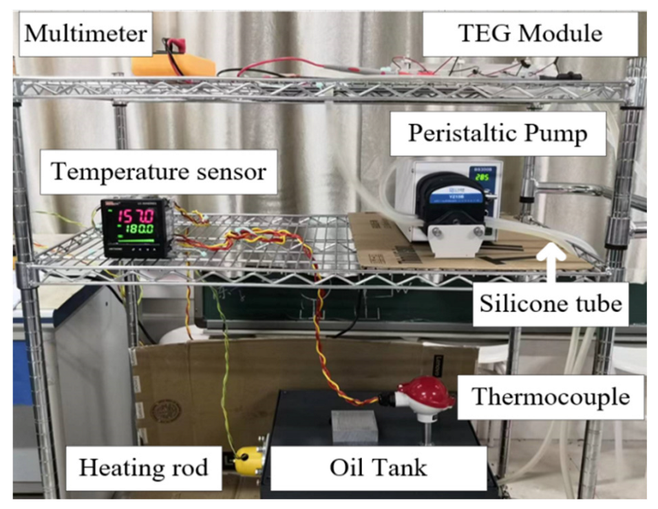
After the experimental platform is installed, the experimental system needs to be debugged to ensure that the relay can operate accurately without any leaks. In order to maintain the accuracy of temperature measurement, it is necessary to control the temperature self-tuning of the hot end module. The experimental platform is shown in Figure 10.

4. Experimental Results and Analysis

After setting up the experimental platform and completing the debugging, the experimental research on TEG module is carried out. The experimental research includes the output characteristics of volt-ampere characteristics, output power, variable load, different pump speed, different heat dissipation conditions, series and parallel mode, etc.

4.1. Comparative Analysis of Different Speed of Peristaltic Pump

A TEG module, consisting of five semiconductor thermoelectric plates coated with thermal grease on their surfaces, is assembled in series and sandwiched between aluminum alloy deflectors. This TEG module is then placed in a system that allows it to be heated by hot oil and cooled by tap water. The temperature control system ensures the accuracy of the hot end temperature in real time and maintains a stable temperature difference.
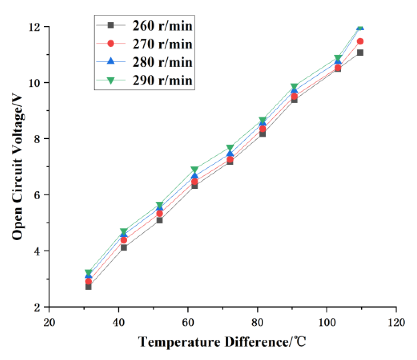
Since the maximum speed of the peristaltic pump is 300 r/min, in order to prevent the pump from running at full load and resulting in reduced service life, the speed of the pump is set as 260 r/min, 270 r/min, 280 r/min and 290 r/min. After the set target temperature value is stabilized, maintain the same temperature difference and change the speed of the pump to measure its open circuit voltage. According to the measurement results, the open circuit voltage diagram at different peristaltic pump speed is shown in Figure 11.
From Figure 11, it can be seen that with the increase of the peristaltic pump’s speed, the open-circuit voltage also increases. The increase of the speed of peristaltic pump increases the heat dissipation efficiency, which indirectly increases the temperature difference. As a result, the TEG module produces an amplified electromotive force. To accommodate the extended operational duration of the double-headed peristaltic pump and the lifespan of the silicone tube, the pump’s velocity is established at 280 r/min.

4.2. Performance Test of Thermoelectric Module

4.2.1. Output Characteristics under Different Heat Dissipation Modes

In order to increase the output voltage and power, Twenty thermoelectric plates coated with thermal grease on both sides constitute a TEG module. In the experiment, the peristaltic pump speed is set to 280 r/min, the corresponding flux of water is 1191 mL/min. At the same time, the temperature control system is used to ensure a stable temperature difference. The TEG system is subjected to experiments employing three different cooling methods: natural air cooling, fan cooling, and water cooling. Output characteristics of these cooling modes are compared and analyzed. Under the premise that the temperature of the hot end is 150 °C and the load resistance is 50 Ohms, and the data is recorded every 10 s. The data are shown in Table 1 below.
When the water cooling heat dissipation is used for the experiment, the inlet water temperature of the aluminum alloy deflector is 30 °C, and the outlet water temperature is 45.5 °C. It can be seen that the output power is basically stable at all times under the three heat dissipation modes. The water cooling heat dissipation mode exhibits the highest output power, while the natural air cooling heat dissipation mode has the lowest output power. Therefore, under the same external conditions, the effect of water cooling is the best.

4.2.2. Analysis of Volt-Ammetry Characteristics

In the experiment, the voltmeter is linked in parallel to the TEG module’s output. Meanwhile, the ammeter is connected in series with the sliding rheostat and subsequently linked in parallel with the voltmeter. Set a fixed temperature difference value of 120 °C (150–30 °C). After the control system is stabilized, change the resistance value, and the data obtained were shown in Table 2 below.
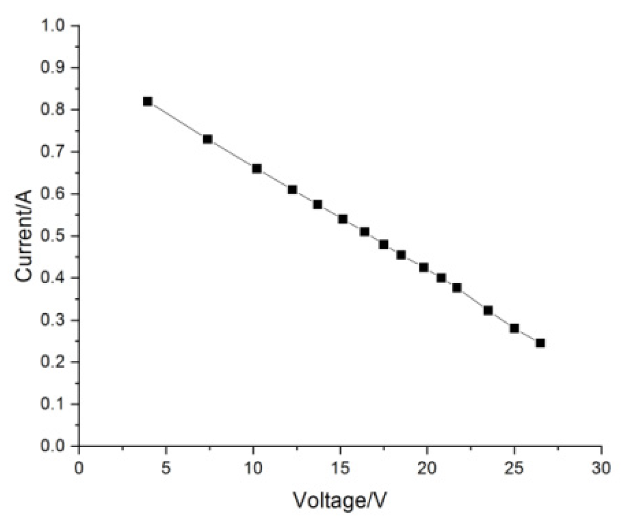
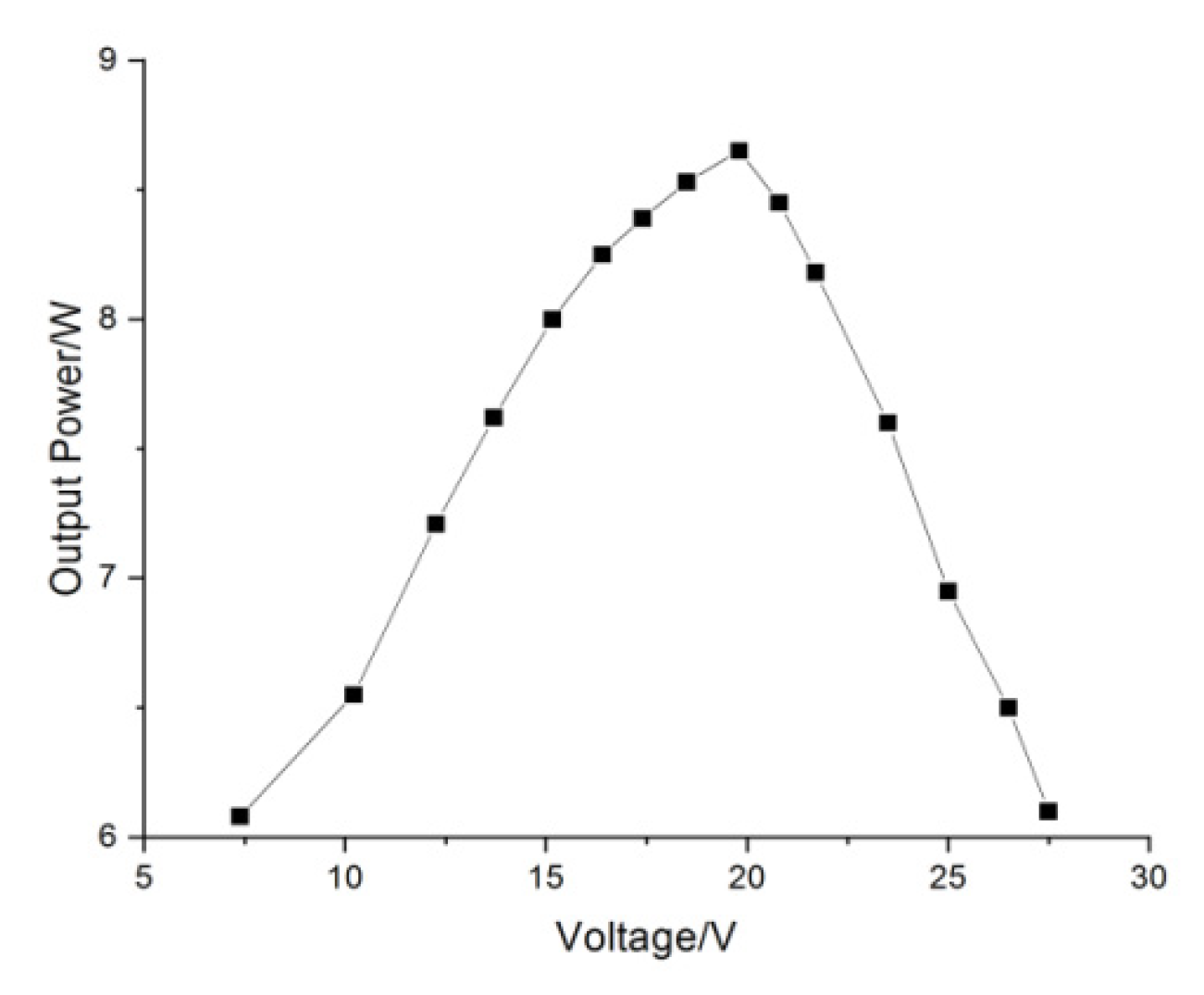
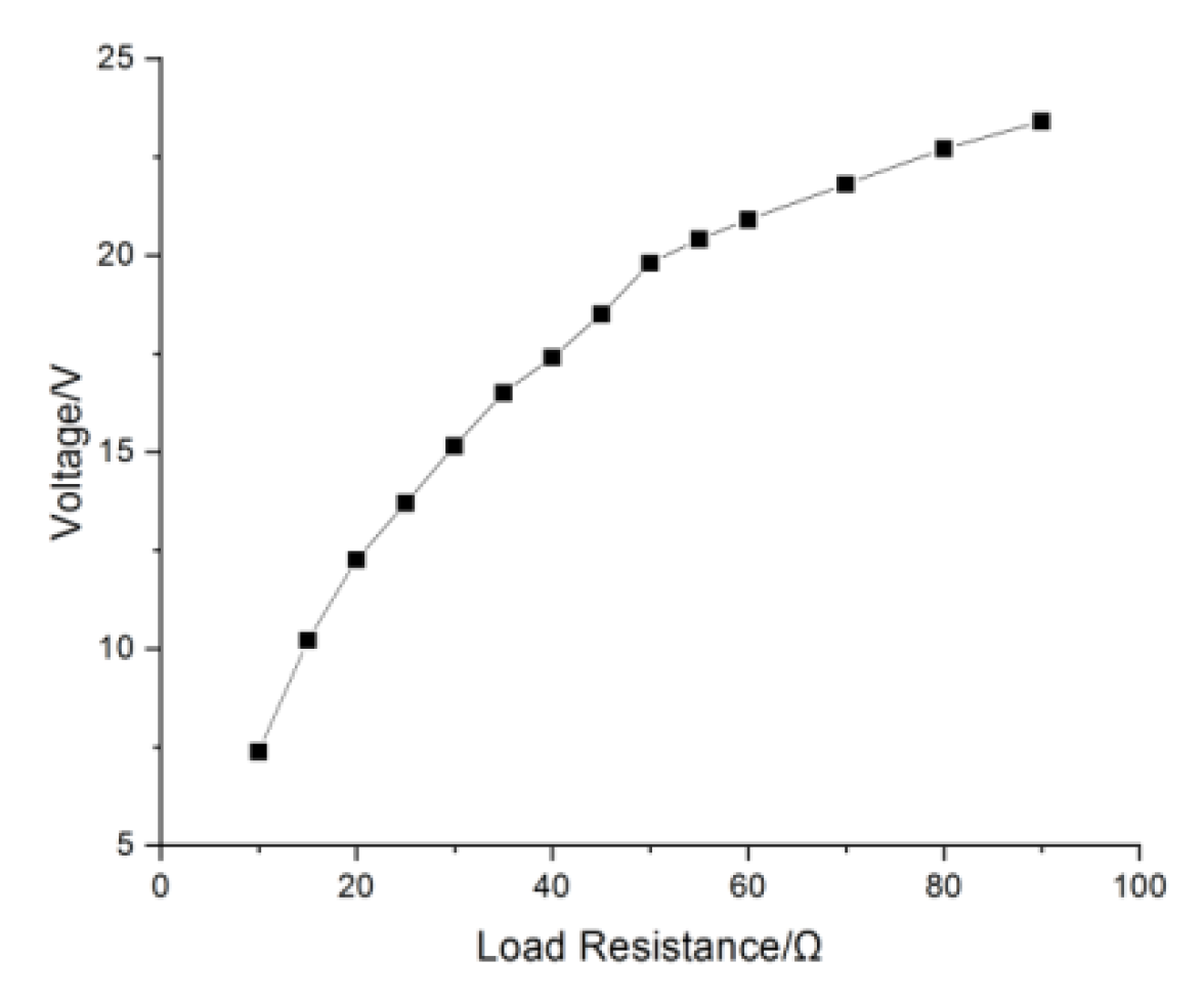
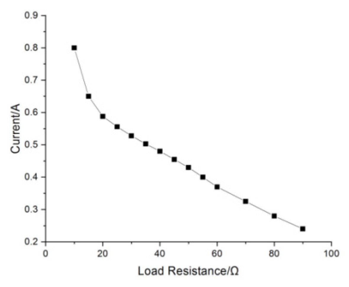
The output characteristics of the TEG module can be obtained from Table 2. As can be seen from the volt-ampere characteristic curve of the TEG module in Figure 12, the load current decreases and the load voltage increases with the increase of the load resistance. As can be seen from the voltage and power relationship curve in Figure 13, the output power of the TEG module presents a parabolic relationship with the increase of output voltage. As the output voltage increases, the output power increases to a maximum. After that, as the output voltage increases, the output power decreases. As can be seen from the load and voltage relationship curve in Figure 14, the voltage increases rapidly with the load and then tends to saturation. As can be seen from the load and current relationship curve in Figure 15, the load resistance is inversely proportional to the output current.
As can be seen from the load and power relationship curve in Figure 16, when the temperature difference remains stable, the external load value is gradually increased, and the output power first keeps increasing to a certain extent and then gradually decreases. This is due to the fact that the output power of the TEG system is dependent on both the output voltage and the load current. Theoretically, only when the resistance value of the external load is equal to the resistance value of the TEG module, the output power reaches the maximum.

4.3. Experiment of Parallel Connection of Thermoelectric Plate

4.3.1. Analysis of Parallel Output Characteristics

The output characteristics of the TEG module in series have been analyzed previously, so the parallel mode of the TEG module is studied and analyzed here. The experiment is carried out on the basis of 20 thermoelectric plates coated with thermal grease and cooled by water. Parallel combination method uses 2 groups (each group of 10 plates in series) thermoelectric plates in parallel. When the temperature difference between the hot and cold ends is 120 °C and remains stable, the load resistance is changed to obtain the measured data, as shown in Table 3.
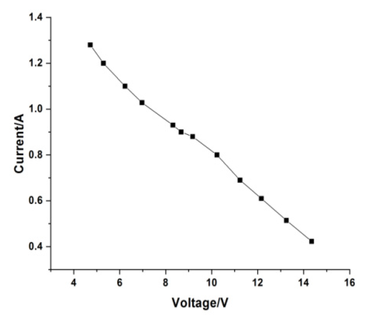
As can be seen from Figure 17, the volt-ampere characteristic curve of the parallel circuit is approximately a straight line. As the load resistance increases, the current decreases and the output voltage increases. During the experiment, the combination mode’s total voltage is lower than the theoretical sum of a single thermoelectric plate. This could be attributed to the increase in thermal radiation during the temperature rise process. The thermal radiation reduces the temperature of hot end to a certain extent, and the change of internal resistance when the temperature rises.
Figure 18 shows the voltage and power characteristic curves of the thermoelectric plate in series and parallel modes with varying load resistance. Under the same conditions, the maximum power obtained by series combination is 8.71 W. When the parallel combination mode is adopted, the maximum power is 8.39 W. Considering the uncertainty of temperature distribution, the current and voltage of the maximum power point are lower than theoretical value. The situation may be the result of a number of factors, includes errors due to uneven temperature distribution across the TEG.

4.3.2. Influence of Load Resistance on Output Power

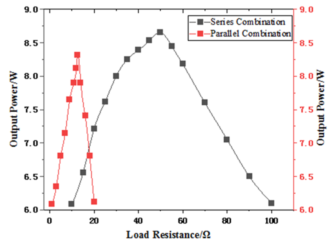
The variation curve of output power with load resistance for the thermoelectric plate in series and parallel mode is shown in Figure 19. The relationship between the output power and the load resistance is parabolic, and the position of the maximum power point is different in different combination modes.
From the previous analysis, theoretically when the load resistance is equal to the equivalent internal resistance, the output power reaches the maximum value. The actual experiment findings suggest that the TEG system yields the maximum power when the load resistance is marginally greater than the internal resistance, with the ratio between the load resistance and internal resistance falling within the range of 1–1.15. Therefore, for the TEG system, it is necessary to consider not only the influence generated by electrical energy, but also the influence generated by thermal energy on the TEG. When TEG is loaded, there will be Peltier effect and Thomson effect, and the larger the temperature difference, the more obvious the effect. At the same time, the higher the temperature, the internal resistance of TEG module will increase.

5. MPPT Algorithm and Simulation of TEG System

The output performance of the TEG system is influenced by several factors, such as the temperature of the hot and cold ends, external load resistance, and connection mode of thermoelectric plates. As a result, the output characteristics of the system are nonlinear. Under certain external conditions, its output power is not stable with the load change, but there is a maximum power point and the corresponding voltage and current [19]. Therefore, it is necessary to control the operating point of the TEG system in the best position to maximize its effectiveness, which is called Maximum Power Point Tracking (MPPT) algorithm.
The maximum output power can be maintained as long as the load resistance and the internal resistance of the TEG module is equal in the circuit. In fact, the measurement of dynamic resistance is very troublesome, and it is impossible to adjust the resistance manually [33], so the PWM signal is used to control the on/off of the switching tube. Figure 20 shows the maximum power output block diagram of TEG system. The TEG module is linked to the load via the DC-DC converter, which controls the switching tube by adjusting the duty cycle of PWM. This enables the TEG system to constantly approach its maximum power point, thereby regulating its operating point in real-time.

5.1. Design of MPPT Algorithm

The MPPT algorithm currently used and their characteristics are as follows [34,35,36]: The constant voltage algorithm is simple and easy to implement, but it is easy to fluctuate due to the influence of external environmental factors, so it is not flexible enough to use. The conductivity increment algorithm has good stability, but its implementation requires high precision of sensor. At the same time, the continuous derivative calculation of the control system also requires a high computing ability. The disturbance observation algorithm has strong applicability, requires less measurement parameters, and has low requirements on controller and sensor, so it is regarded as an ideal control algorithm. However, the fixed disturbance step size has a great influence on the overall performance of the system, resulting in energy loss. The application of artificial intelligence algorithms in controlling TEG systems with variable temperature difference operating conditions has significant theoretical advantages. However, the complexity and cost of implementation currently limit its practical application.
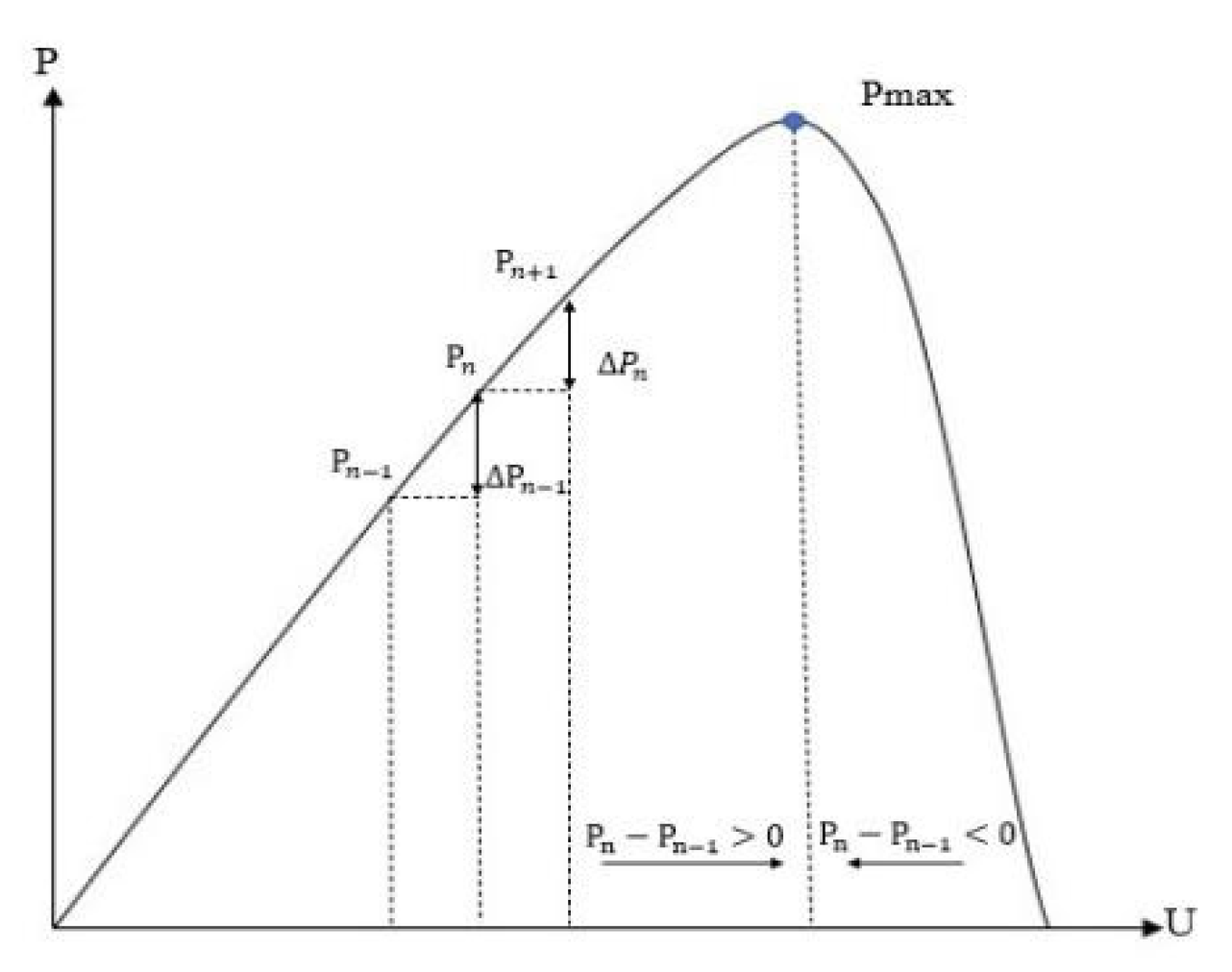
For the selection of MPPT algorithms [37,38], in addition to the characteristics of each algorithm itself, we should also consider the difficulty of implementing the control algorithm, economic cost, the type of sensor, tracking speed and accuracy, etc. Based on the above analysis, the interference observation algorithm is selected in this paper. Since the traditional interference observation algorithm uses a fixed disturbance quantity, it cannot meet the dynamic performance and stability accuracy requirements of MPPT tracking at the same time. Based on this, an adaptive variable step size improved MPPT algorithm based on power prediction is designed. The algorithm takes power change as step size control quantity, the control schematic diagram is shown in Figure 21.
According to the control schematic diagram: when Δ P = P n P n 1 = 0 , it indicates that the output power reaches the maximum value; When   Δ P = P n P n 1 > 0 , the TEG module works on the left side of the maximum power point; When   Δ P = P n P n 1 < 0 , the TEG module works on the right side of the maximum power point.
In the same disturbance interval of Δ U , when Δ P n Δ P n 1 , the variation trend of the output power increases at this time and is far from the maximum power point, the method of large step search approximation is adopted, taking step C 1 = Δ P n + Δ P n 1 Δ P n 1 M 2 M . when Δ P n < Δ P n 1 , the variation trend of the output power reduces at the time and is close to the maximum power point, the method of small step search approximation is adopted, taking step C 2 = Δ P n 1 Δ P n + Δ P n 1 M . The improved MPPT algorithm flow chart is shown in Figure 22.
Then the value of Δ P n × Δ U is judged, and when its value is greater than 0, the value of U n is equal to U n 1 + C. Otherwise, judge whether Δ P n × Δ U is equal to zero, if so, U n is equal to the value of U n 1 . If not, the value of U n is equal to U n 1 -C.
Therefore, at the working point far from the maximum power point, a large step size is adopted to improve the tracking speed and optimize the dynamic performance. At the working point close to the maximum power point, the perturbation with small step size is used to reduce the amplitude of oscillation and improve the stability of the system. The enhanced interference observation algorithm, featuring a variable step size, can satisfy the demands of promptness and stable accuracy, diminish unnecessary energy loss, and enhance system efficacy.

5.2. Simulation Analysis

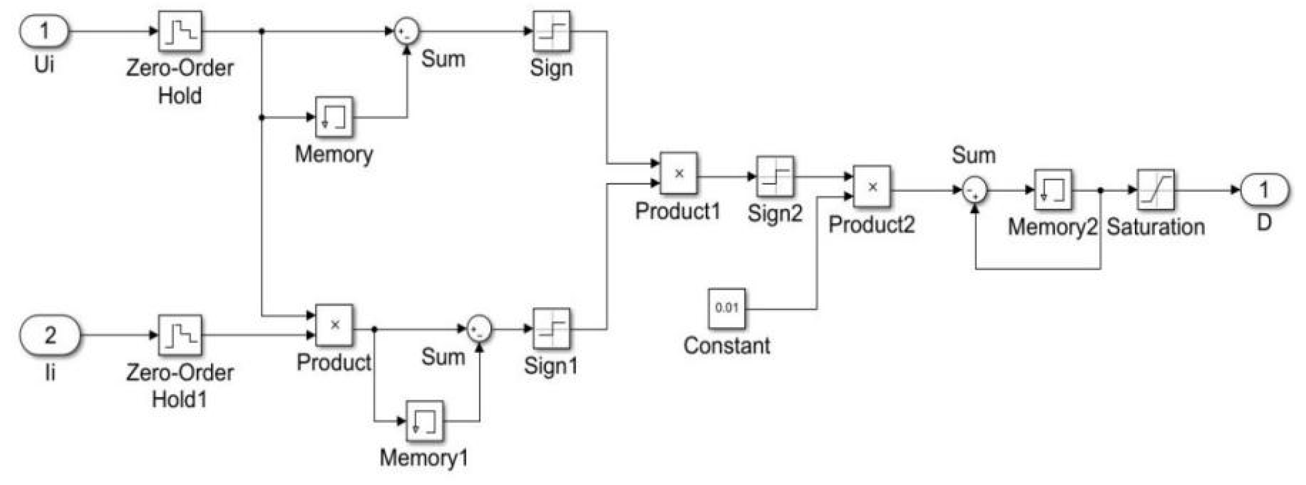
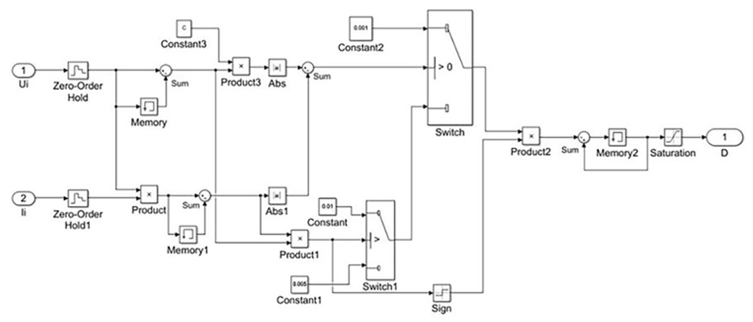
Matlab/Simulink software is used to simulate and analyze the MPPT algorithm, and the simulation structure diagram of the traditional interference observation algorithm and the improved MPPT algorithm are built in the paper. The simulation structure diagram of traditional algorithm is shown in Figure 23, and the simulation structure diagram of the improved MPPT algorithm is shown in Figure 24.
The models are integrated and packaged as subsystem modules to facilitate the combination of all models into a complete TEG simulation system. The complete TEG simulation system model is shown in Figure 25.
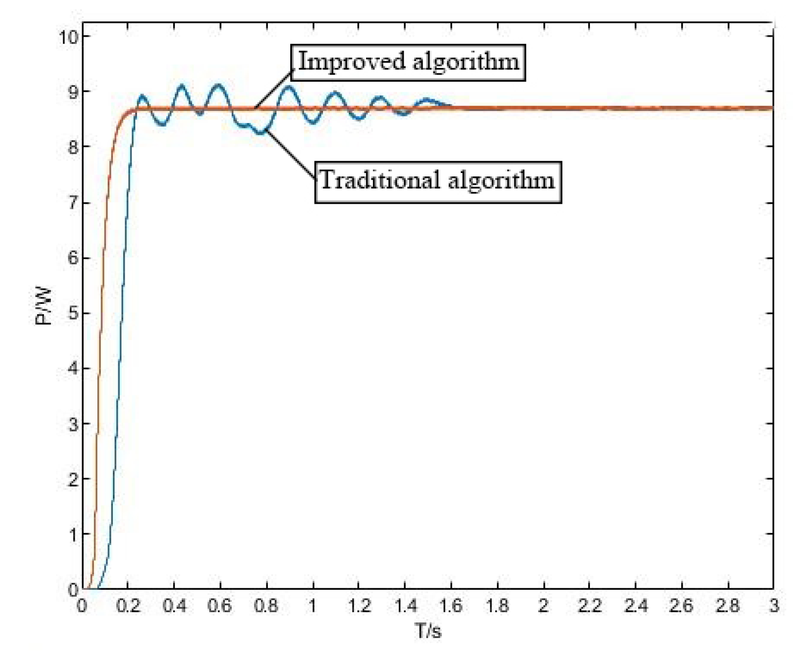
After setting relevant parameters, the two MPPT algorithms are simulated, and the simulation results are shown in Figure 26. It can be seen from the figure that the time for the improved algorithm to reach the stable maximum power point is about 0.21 s, while the traditional algorithm has a large fluctuation in the early stage and reaches the stable maximum power point at about 1.75 s. Therefore, compared with the traditional interference observation algorithm, the improved MPPT algorithm can reach the stable maximum power point more quickly, and the fluctuation after reaching stable the maximum power point is smaller, which reduces the energy loss and improves the dynamic performance.

6. Conclusions

As a green power generation method, TEG provides a new idea for energy conservation and environmental protection. Taking The waste heat of low grade boiler flue gas as the research object, the overall design scheme of TEG system is designed in this paper. An experimental device was set up to simulate the temperature condition of flue gas waste heat. During the experiment, the fixed temperature difference was set at 120 °C (hot end: 150 °C~cold end: 30 °C), and the output characteristics of TEG system are analyzed.
(1)
The uniformity of temperature distribution at the hot and cold ends of the TEG module affects the output power, and the coating of thermal grease on the thermoelectric plate can effectively improve the uniformity of temperature distribution. The evenness of temperature distribution at both the hot and cold ends of the TEG module has an impact on the output power. Applying a layer of thermal grease on the thermoelectric plate can effectively enhance the uniformity of temperature distribution. The use of water cooling heat dissipation and higher peristaltic pump speed can effectively maintain the temperature difference and increase the output efficiency. To enhance the output efficiency and maintain the temperature difference, utilizing water cooling heat dissipation and elevating the peristaltic pump speed are effective measures. To accommodate the extended operational duration of the double-headed peristaltic pump and the lifespan of the silicone tube, the pump’s velocity is established at 280 r/min. The velocity of the double-headed peristaltic pump has been set at 280 r/min to ensure the extended operational duration of the pump and the lifespan of the silicone tube.
(2)
Under the same conditions, the maximum power of 20 thermoelectric plates in series is slightly greater than that of parallel combination. This is due to the error caused by the uncertainty of temperature and the uneven transverse temperature distribution of a single TEG.
(3)
In traditional medium to high temperature TEG systems, it is generally believed that the maximum output power of the system is achieved when the load resistance is equal to the internal resistance of the TEG module. Typically, in traditional medium to high temperature TEG systems, it is commonly believed that the maximum output power of the system can be attained when the load resistance is equivalent to the internal resistance of the TEG module. In the experiment, it was found that when the fixed temperature difference is set to 120 °C, the maximum output power is generated when the load resistance is slightly greater than the internal resistance, and the ratio of the load resistance to the internal resistance is about 1–1.15. Therefore, it is necessary to consider not only the influence of electric energy, but also the influence of heat energy for TEG module. When TEG is loaded, Partier effect and Thomson effect are produced, and the larger the temperature difference, the more obvious the phenomenon.
(4)
In order to output the maximum power, an adaptive variable step size improved MPPT algorithm based on power prediction is designed. According to the simulation results, the time taken by the improved algorithm to achieve the stable maximum power point is approximately 0.21 s, whereas the traditional algorithm takes around 1.75 s to reach the stable maximum power point. The time of the improved algorithm to reach the stable maximum power point is 1.54 s faster than that of the traditional algorithm. So the improved algorithm can reach the stable maximum power point more quickly and with less fluctuation than the traditional algorithm. The improved MPPT algorithm can meet the requirements of rapidity and stability accuracy of TEG system and reduce the energy loss.
The designed TEG system can meet the requirements of waste heat recovery, and it has a broad application prospect in low grade energy utilization. The research results have reference significance for the application of TEG technology in the field of low-grade waste heat recovery.

Author Contributions

Funding acquisition and writing—original draft preparation, Y.G.; Methodology, S.Z.; Resources, G.C.; Writing—review and editing, S.Z. and Y.G. All authors have read and agreed to the published version of the manuscript.

Funding

The research was partially supported by the National Nature Science Foundation of China (Grant No. 62073090) and the FDCT of Macau (Grant No. 0065/2019/A2).

Institutional Review Board Statement

Not applicable.

Informed Consent Statement

Not applicable.

Data Availability Statement

Some or all data, models, or code that support the findings of this study are available from the corresponding author upon reasonable request.

Conflicts of Interest

The authors declare no conflict of interest.

References

  1. Hilmin, M.H.M.; Remeli, M.; Singh, B.; Affandi, N. Thermoelectric power generations from vehicle exhaust gas with TiO2 nanofluid cooling. Therm. Sci. Eng. Prog. 2020, 18, 100558. [Google Scholar] [CrossRef]
  2. Burnete, N.V.; Mariasiu, F.; Moldovanu, D.; Depcik, C. Simulink Model of a Thermoelectric Generator for Vehicle Waste Heat Recovery. Appl. Sci. 2021, 11, 1340. [Google Scholar] [CrossRef]
  3. Shah, K.W.; Wang, S.-X.; Zheng, Y.; Xu, J. Solution-Based Synthesis and Processing of Metal Chalcogenides for Thermoelectric Applications. Appl. Sci. 2019, 9, 1511. [Google Scholar] [CrossRef]
  4. Alptekin, M.; Calisir, T.; Baskaya, S. Design and experimental investigation of a thermoelectric self-powered heating system. Energy Convers. Manag. 2017, 146, 244–252. [Google Scholar] [CrossRef]
  5. Fanciulli, C.; Abedi, H.; Merotto, L.; Dondè, R.; De Iuliis, S.; Passaretti, F. Portable thermoelectric power generation based on catalytic combustor for low power electronic equipment. Appl. Energy 2018, 215, 300–308. [Google Scholar] [CrossRef]
  6. Li, G.; Zheng, Y.; Guo, W.; Zhu, D.; Tang, Y. Mesoscale combustor-powered thermoelectric generator: Experimental optimization and evaluation metrics. Appl. Energy 2020, 272, 115234. [Google Scholar] [CrossRef]
  7. Quan, R.; Wang, C.; Wu, F.; Chang, Y.; Deng, Y. Parameter matching and optimization of an isg mild hybrid powertrain based on an automobile exhaust thermoelectric generator. J. Electron. Mater. 2020, 49, 2734–2746. [Google Scholar] [CrossRef]
  8. Maneewan, S.; Khedari, J.; Zeghmati, B.; Hirunlabh, J.; Eakburanawat, J. Investigation on generated power of thermoelectric roof solar collector. Renew. Energy 2004, 29, 743–752. [Google Scholar] [CrossRef]
  9. Konstantinou, G.; Kyratsi, T.; Louca, L. Design of a Thermoelectric Device for Power Generation through Waste Heat Recovery from Marine Internal Combustion Engines. Energies 2022, 15, 4075. [Google Scholar] [CrossRef]
  10. Attar, A.; Rady, M.; Abuhabaya, A.; Albatati, F.; Hegab, A.; Almatrafi, E. Performance Assessment of Using Thermoelectric Generators for Waste Heat Recovery from Vapor Compression Refrigeration Systems. Energies 2021, 14, 8192. [Google Scholar] [CrossRef]
  11. Barma, M.; Riaz, M.; Saidur, R.; Long, B. Estimation of thermoelectric power generation by recovering waste heat from Biomass fired thermal oil heater. Energy Convers. Manag. 2015, 98, 303–313. [Google Scholar] [CrossRef]
  12. Luo, Y.; Li, L.; Chen, Y.; Kim, C. Influence of geometric parameter and contact resistances on the thermal-electric behavior of a segmented TE. Energy 2022, 254, 124487. [Google Scholar] [CrossRef]
  13. Jia, Y.; Zhang, Z.; Wang, C.; Sun, H.; Zhang, W. Design and parameter study of a thermoelectric generator for waste heat recycling in flexible micro-light-emitting diodes. Appl. Therm. Eng. 2022, 200, 117568. [Google Scholar] [CrossRef]
  14. Chen, L.; Yu, Z.; Yuan, Y.; Zhang, J.; Lee, J. Electrical performance optimization of a transverse-Seebeck-effect-based tubular thermoelectric generator for waste heat recovery. Energy Rep. 2022, 8, 7589–7599. [Google Scholar] [CrossRef]
  15. Yin, T.; Li, W.; Li, K.; He, Z. Multi-parameter optimization and uncertainty analysis of multi-stage thermoelectric generator with temperature-dependent materials. Energy Rep. 2021, 7, 7212–7223. [Google Scholar] [CrossRef]
  16. Assareh, E.; Alirahmi, S.M.; Ahmadi, P. A sustainable model for the integration of solar and geothermal energy boosted with thermoelectric generators (TEGs) for electricity, cooling and desalination purpose. Geothermics 2021, 92, 102042. [Google Scholar] [CrossRef]
  17. Brazdil, M.; Pospisil, J. Thermoelectric power generation utilizing the waste heat from a biomass boiler. J. Electron. Mater. 2013, 42, 2198–2202. [Google Scholar] [CrossRef]
  18. Shittu, S.; Li, G.; Zhao, X.; Ma, X. Series of detail comparison and optimization of thermoelectric element geometry considering the pv effect. Renew. Energy 2019, 130, 930–942. [Google Scholar] [CrossRef]
  19. Montecucco, A.; Knox, A.R. Maximum power point tracking converter based on the open-circuit voltage method for thermoelectric generators. IEEE Trans. Power Electron. 2015, 30, 828–839. [Google Scholar] [CrossRef]
  20. Fauzan, M.Y.; Muyeen, S.M.; Islam, S. Enhanced power extraction from thermoelectric generators considering non-uniform heat distribution. Energy Convers. Manag. 2021, 246, 114565. [Google Scholar] [CrossRef]
  21. Cózar, I.R.; Pujol, T.; Lehocky, M. Numerical analysis of the effects of electrical and thermal configurations of thermoelectric modules in large-scale thermoelectric generators. Appl. Energy 2018, 229, 264–280. [Google Scholar] [CrossRef]
  22. Aranguren, P.; Araiz, M.; Astrain, D.; Martínez, A. Thermoelectric generators for waste heat harvesting: A computational and experimental approach. Energy Convers. Manag. 2017, 148, 680–691. [Google Scholar] [CrossRef]
  23. Beltrán-Pitarch, B.; Vidan, F.; García-Caadas, J. Thermal contact resistance evaluation of a thermoelectric system by means of three i-v curves. Int. J. Heat Mass Transf. 2021, 173, 121247. [Google Scholar] [CrossRef]
  24. Khalil, H.; Hassan, H. 3d study of the impact of aspect ratio and tilt angle on the thermoelectric generator power for waste heat recovery from a chimney. J. Power Sources 2019, 418, 98–111. [Google Scholar] [CrossRef]
  25. Zhang, H.; Yue, H.; Huang, J.; Liang, K.; Chen, H. Experimental studies on a low concentrating photovoltaic/thermal (LCPV/T) collector with a thermoelectric generator (TEG) module. Renew. Energy 2021, 171, 1026–1040. [Google Scholar] [CrossRef]
  26. Kirihara, K.; Wei, Q.; Mukaida, M.; Ishida, T. Thermoelectric power generation using nonwoven fabric module impregnated with conducting polymer PEDOT: PSS. Synth. Met. 2017, 225, 41–48. [Google Scholar] [CrossRef]
  27. Xu, G.; Huang, S.; Yang, Y.; Wu, Y.; Zhang, K.; Xu, C. Techno-economic analysis and optimization of the heat recovery of utility boiler flue gas. Appl. Energy 2013, 112, 907–917. [Google Scholar] [CrossRef]
  28. Wu, H.; Chen, B.; Cheng, H. The pn conduction type transition in Ge-incorporated Bi2Te3 thermoelectric materials. Acta Mater. 2017, 122, 120–129. [Google Scholar] [CrossRef]
  29. Kütt, L.; Millar, J.; Karttunen, A.; Lehtonen, M.; Karppinen, M. Thermoelectric applications for energy harvesting in domestic applications and micro-production units. Part I: Thermoelectric concepts, domestic boilers and biomass stoves. Renew. Sustain. Energy Rev. 2018, 98, 519–544. [Google Scholar] [CrossRef]
  30. Zhang, Y.; Li, X.; Sun, C.; He, Z. Improved step load response of a dual-active-bridge DC–DC converter. Electronics 2018, 7, 185. [Google Scholar] [CrossRef]
  31. Hu, S.; Li, X.; Zheng, Q. A dual-bridge DC–DC resonant converter using extended PWM and phase-shift control. IEEE Trans. Ind. Appl. 2021, 57, 4009–4020. [Google Scholar] [CrossRef]
  32. Zhou, S.; Li, X.; Chen, G.; Hu, S. A piecewise control strategy for a bidirectional series resonant converter. Electronics 2018, 7, 374. [Google Scholar] [CrossRef]
  33. Mamur, H.; Coban, Y. Detailed modeling of a thermoelectric generator for maximum power point tracking. Turk. J. Electr. Eng. Comput. Sci. 2020, 28, 124–139. [Google Scholar] [CrossRef]
  34. Leoni, A.; Pantoli, L. SPICE Model Identification Technique of a Cheap Thermoelectric Cell Applied to DC/DC Design with MPPT Algorithm for Low-Cost, Low-Power Energy Harvesting. Appl. Sci. 2019, 9, 3744. [Google Scholar] [CrossRef]
  35. Miao, J.; Chen, H.; Lei, Y.; Lv, Y.; Liu, W.; Song, Z. MPPT Circuit Using Time Exponential Rate Perturbation and Observation for Enhanced Tracking Efficiency for a Wide Resistance Range of Thermoelectric Generator. Appl. Sci. 2021, 11, 4650. [Google Scholar] [CrossRef]
  36. Chihaia, R.-A.; Vasile, I.; Cîrciumaru, G.; Nicolaie, S.; Tudor, E.; Dumitru, C. Improving the Energy Conversion Efficiency for Hydrokinetic Turbines Using MPPT Controller. Appl. Sci. 2020, 10, 7560. [Google Scholar] [CrossRef]
  37. Yahya, K.; Alomari, O. A new maximum power point tracking algorithm based on power differentials method for thermoelectric generators. Int. J. Energy Res. 2021, 45, 7476–7486. [Google Scholar] [CrossRef]
  38. Darcy Gnana Jegha, A.; Subathra, M.S.P.; Manoj Kumar, N.; Subramaniam, U.; Padmanaban, S. A High Gain DC-DC Converter with Grey Wolf Optimizer Based MPPT Algorithm for PV Fed BLDC Motor Drive. Appl. Sci. 2020, 10, 2797. [Google Scholar] [CrossRef]
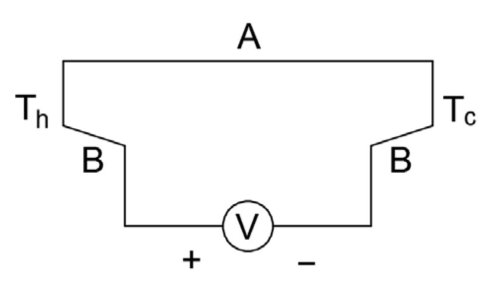
Figure 1. Schematic diagram of Seebeck effect.
Applsci 13 05673 g001
Figure 2. Equivalent circuit of thermoelectric module.
Applsci 13 05673 g002
Figure 3. Schematic diagram of TEG system.
Applsci 13 05673 g003
Figure 4. Schematic diagram of TEG experimental device.
Applsci 13 05673 g004
Figure 5. Internal structure diagram of aluminum alloy guide plate.
Applsci 13 05673 g005
Figure 6. Schematic diagram of hot end module.
Applsci 13 05673 g006
Figure 7. Schematic diagram of double-layer TEG module.
Applsci 13 05673 g007
Figure 8. Circuit diagram of the DC-DC module.
Applsci 13 05673 g008
Figure 9. Schematic diagram of the experimental device.
Applsci 13 05673 g009
Figure 10. The experimental platform.
Applsci 13 05673 g010
Figure 11. Diagram of open circuit voltage at different peristaltic pump speed.
Applsci 13 05673 g011
Figure 12. Diagram of volt-ammetry characteristics.
Applsci 13 05673 g012
Figure 13. Diagram of voltage and power.
Applsci 13 05673 g013
Figure 14. Diagram of load and voltage.
Applsci 13 05673 g014
Figure 15. Diagram of load and current.
Applsci 13 05673 g015
Figure 16. Diagram of load and power.
Applsci 13 05673 g016
Figure 17. Diagram of volt-ammetry characteristics.
Applsci 13 05673 g017
Figure 18. Diagram of voltage and power.
Applsci 13 05673 g018
Figure 19. Diagram of Output power and load.
Applsci 13 05673 g019
Figure 20. Maximum power output block diagram of TEG system.
Applsci 13 05673 g020
Figure 21. Control schematic diagram of improved algorithm.
Applsci 13 05673 g021
Figure 22. Flow chart of improved MPPT algorithm.
Applsci 13 05673 g022
Figure 23. Simulation structure diagram of traditional MPPT algorithm.
Applsci 13 05673 g023
Figure 24. Simulation structure diagram of improved MPPT algorithm.
Applsci 13 05673 g024
Figure 25. Simulation model diagram of TEG system.
Applsci 13 05673 g025
Figure 26. Comparison of simulation results of two MPPT algorithms.
Applsci 13 05673 g026
Table 1. Output data under different heat dissipation modes.
Heat-Dissipating
Method
Power/W
(T = 10 S)
Power/W
(T = 20 S)
Power/W
(T = 30 S)
Water cooling8.7128.7158.706
Fan cooling8.5268.5228.517
natural air cooling8.2868.2818.283
Table 2. Output characteristic data of TEG module.
Load Voltage/VLoad Current/APower/W
7.680.816.08
10.210.646.55
12.260.597.21
13.70.567.62
15.150.538
16.40.508.25
17.40.488.39
18.50.468.51
19.80.448.71
20.80.418.45
21.70.388.18
23.50.327.6
250.287.05
26.50.256.5
27.50.226.05
Table 3. Output characteristic data of TEG module.
Load Voltage/VLoad Current/APower/W
4.721.296.09
5.291.26.35
6.231.16.85
6.971.037.17
8.310.927.65
8.670.97.8
9.170.877.98
10.230.828.39
11.230.77.86
12.160.617.42
13.250.516.76
14.390.426.05
Disclaimer/Publisher’s Note: The statements, opinions and data contained in all publications are solely those of the individual author(s) and contributor(s) and not of MDPI and/or the editor(s). MDPI and/or the editor(s) disclaim responsibility for any injury to people or property resulting from any ideas, methods, instructions or products referred to in the content.