Abstract
As an effective resolution enhancement technology, source optimization (SO) is considered key for significantly improving the image quality of optical lithography at advanced nodes. To solve the problem of unsatisfactory SO performance, it is necessary to combine it with optimization algorithms. In this study, an SO method based on a hybrid genetic algorithm is proposed to achieve an acceptable source shape in the imaging process for optical lithography. To overcome the problems of local optima and the small search scope, an update strategy that uses particle swarm optimization and the tabu list method from the tabu search algorithm are utilized to enhance the optimization performance. Meanwhile, different feature patterns were employed as the input of the optimization model. These simulation results show that the proposed SO method exhibits dominant optimization performance for SO in optical lithography.
1. Introduction
Optical lithography is a critical part of the manufacturing of very-large-scale integrated circuits (VLSIs), and it can be used to implement pattern transfer from a mask to a wafer with a reduction in the magnification by using the optical projection method [1,2,3]. The imaging process in optical lithography is shown in Figure 1. The rays emitted by an illumination source pass through a group of optical mirrors to form Kohler illumination. These rays irradiate the mask to generate diffracted light, which carries the feature information. An objective lens collects the diffracted light, which finally creates an image on the surface of a wafer. Because of the low-pass filtering effect of the objective lens, the high-frequency information of the feature pattern is lost, which causes aerial image to be distorted. Therefore, improving the imaging quality in optical lithography is essential in current advanced technology nodes.
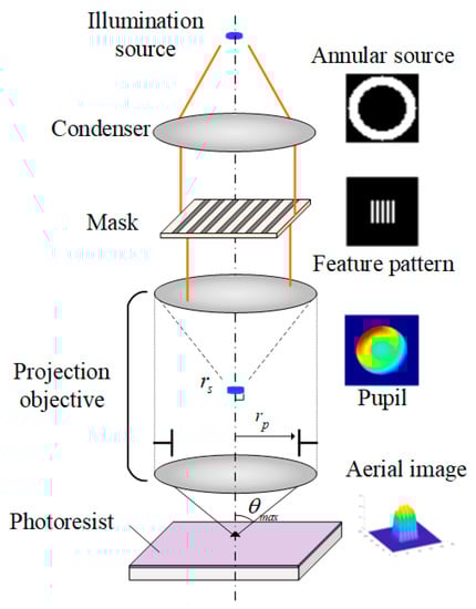
Figure 1.
Schematic representation of the optical lithographic imaging process represents the effective radius of the illumination source, is the radius of the pupil, and is the maximal incident angle of the rays in the objective exit.
According to the Rayleigh criterion , the lithographic resolution () can be absolutely improved to shrink the illumination wavelength () and increase the numerical aperture () of the objective lens, where is the process factor [4,5]. In advanced nodes, the loss of high-frequency information is becoming more and more serious, and this causes an obvious optical proximity effect (OPE) [6,7]. These two approaches can no longer guarantee that the imaging quality requirements of continuously evolving technology will be met. Several resolution enhancement technologies (RETs) for the attainment of high-quality aerial image have been proposed [8,9,10]. In these methods, pixelated source optimization (SO), which is an inverse optimization method, can efficiently promote the performance in optical lithographic imaging [11,12,13]. This can be achieved with mathematical and algorithmic approaches, which can inversely optimize the intensity distribution of an optical lithographic source according to aerial image or resistance pattern. The enhancement of optimization performance with pixelated SO methods has become a research hotspot.
Freeform illuminations, which can be created with a set of micromirror arrays, have been developed to provide more degrees of freedom for regulating the illumination shape in optical lithography [11,14,15]. In a pixelated source model, changes in intensity of the pixels can indicate the mirror flip angle, where a pixel represents a unit mirror.
To improve the imaging quality in optical lithography, various types of pixelated SO methods have been proposed; of these, gradient-based methods, such as gradient descent (GD) [16], conjugate gradient (CG) [17,18], and steepest descent (SD) [19], have become the most significant. As local optimization algorithms, gradient-based methods have quick convergence, robustness, and the ability to search for the optimal solution [16,20,21]. These methods are not limited by the size of the optimized matrix, but only depend on the complexity of the gradient function. However, with the decrease in the critical dimensions of feature patterns toward smaller process nodes, the complexity of photo-resistance models is continuously expanded. It is significantly complicated to derive the gradient function of a photo-resistance model. Furthermore, the optimal solutions of complex models have an increased probability of falling into local optima when applying these methods to process the optimization of lithographic sources in advanced applications. To improving the imaging performance in optical lithography, it is not enough to address the optimization efficiency.
The genetic algorithm (GA), which is a typical example of a heuristic approach, has been widely employed as a key tool for achieving the optimization of complex models in several fields, such as production scheduling, image processing, and data mining [22,23]. N. Sortrakul et al. utilized a GA to solve a comprehensive optimization model for production scheduling and preventive maintenance planning [24]. Zhang et al. used a new adaptive operator to achieve a nonlinear adaptive adjustment for image segmentation via a GA [25]. Tzung et al. found a suitable membership function for a mining problem through a GA-based framework and applied the best-set membership function in fuzzy association rule mining [26]. As this is a global optimization method, it is more convenient to find the optimal condition of the merit function for a complex model because of its gradient-free features. Moreover, due to its inherent property of being based on a probabilistic rule, the more flexible search function of a GA can be implemented to decrease the influence of multiple parameters of a complex model to improve the optimization efficiency. Several studies have indicated that GAs have displayed considerable capacities for optimizing the imaging performance in optical lithography. Fuhner et al. proposed that it is significantly effective to improve the imaging quality by using a GA to optimize the illumination geometries in optical lithography [27]. Li et al. applied a GA for optical proximity correction to compensate for the image distortion induced by the optical proximity effect [28]. Hong et al. used a modified GA method to improve the process windows in inverse lithography for various common objectives, including the depth of focus, normalized image log slope, and process variability band [29]. Nevertheless, the multiple parameters of a complex model potentially cause the search range of an optimization model based on a GA to be reduced, thus causing premature convergence [30,31]. Due to the scalability of GAs, it is possible to combine a GA with other algorithms to enhance the optimization capabilities and improve the convergence efficiency [24,32,33]. To achieve the optimal source shape in the imaging process of optical lithography for advanced applications, a hybrid GA can be considered as an effective approach for complex imaging models.
In this study, a hybrid algorithm created by combining a GA with two decision methods is proposed to find the optimal illumination mode according to different feature patterns in order to improve the imaging performance in optical lithography. These decision methods are the iterative search approaches of the tabu search algorithm (TS) and particle swarm optimization algorithm (PSO). Because of the complex model of the optical lithographic imaging process, the convergence efficiency of GA-based SO methods is limited and can be excessively reduced. To overcome the search limitations, an update strategy using PSO can expand the search scope. The tabu list function from the TS can improve the optimization capabilities within a reasonable range. Furthermore, the combination of a crossover operation and mutation operation in the GA can ensure the diversification of the population for the SO model. The simulation results prove that the imaging performance in optical lithography can be significantly improved by utilizing an SO method with the proposed hybrid GA approach.
2. Methodology
2.1. Partially Coherent Imaging Model
The forward imaging process in optical lithography can be described by a partially coherent imaging model (PCI), which is equivalent to the superposition of a series of coherent images. Assuming that a point source on the optical axis is utilized to complete completely coherent imaging (CCI), this imaging process can be expressed as follows [34]:
where are the spatial coordinates in the imaging plane, are the spectral coordinates of the pupil, and are the spectral coordinates of the mask spectrum. represents the intensity distribution of an image obtained via CCI. , which is a pupil function, can be regarded as a low-pass filter, which severely restricts the higher-order diffraction information of the feature pattern from participating in the imaging process. In addition, it can be used to simulate the effects of defocus, aberration, and apodization by modifying the phase information of the pupil. denotes the frequency spectrum of the feature pattern in the mask, which can be acquired with a Fourier transform operation. To facilitate the imaging process of optical lithography, the illumination source can be depicted as discrete matrices with a pixelated representation, where a pixel represents a point source. For the off-axis point source, in the process of PCI, the imaging process can be implemented by shifting the pupil according to the position of this point source. The intensity distribution of an image obtained via PCI can be found by accumulating the images obtained by each point source. Hence, the intensity distribution of an aerial image for optical lithography can be calculated as follows:
In Equation (2), I(x,y) represents the intensity distribution of an aerial image for optical lithography. J(f,g) is a discrete illumination source. In order to concisely express the imaging process of PCI, Equation (2) can be transformed into a format for matrix multiplication—a source matrix and mask matrix—and the result of CCI can be described by using the illumination cross-coefficient (ICC).
To evaluate the imaging performance in optical lithography, it is vital to describe the resistance patterns on the surface of a wafer. In this study, the formation process of a resistance pattern can be approximately explained by a sigmoid model, which is given by:
In Equation (4), represents the contour layout of the resistance pattern formed due to the photo-resistance effect. is a sigmoid function that can approximately achieve a binary distribution. The parameters and denote the steepness index and the threshold of photo-resistance, respectively.
2.2. Flow of Hybrid-GA-Based SO
2.2.1. Pattern Error Minimization Problem
In a complicated optimization model, it is essential to construct an efficient merit function that can distinctly describe the convergence tendency of an iteration process. For the proposed hybrid optimization approach based on a heuristic algorithm, the optimization process has no complex gradient derivation procedures for the merit function. In this study, the pattern error (PE) is regarded as the merit function, and it is defined as the absolute sum of the unit differences between the mask and resistance patterns,
where represents the value of the PE for each iteration in the optimization model, and is the discrete matrix formation of the mask. It is assumed that the mask is a 2D matrix with a size of , which has the form of the binary distribution. The value of each pixel is set to 0 or 1. Let and be represented by the real matrices, which are denoted by and , respectively. Equation (5) shows that the minimum value of the PE can be achieved by updating the intensity distribution of the illumination source to cause the resistance pattern to be closer to the mask layout throughout the iterative process.
2.2.2. The Optimization Strategy for the Illumination Source
In imaging systems for optical lithography, an extended source is employed as the illumination source, and is deemed to be partially coherent illumination. According to their different partial coherence factors and different intensity distributions, the illumination modes can be divided into circular illumination, annular illumination, dipolar illumination, quadrupole illumination, etc. In this study, the annular illumination mode is utilized as the initial source in the proposed SO model, as shown in Figure 2. The partially coherent factor () of this annular source is determined by the source’s effective radius () and the pupil’s radius (), . For annular illumination in the optimization model, the maximum and minimum partially coherent factors are, respectively, and , where and are the maximum and minimum radiuses of the illumination source, respectively.
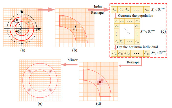
Figure 2.
Schematic of the optimization of a lithographic source by using the proposed SO method. In (a), the dotted circle represents a circle with a radius of 1. The annular source is divided into four identical parts: , ,, and . is utilized as the optimized region, which is shown in the form of a shadow. (b) The optimized region of the source; (c) the flow of matrix manipulation; (d) the optimized shape of ; (e) the intensity distribution of the optimal source.
Because of a special property of symmetry with respect to the optical axis, an optical lithographic source can be decomposed into four identical parts according to the axis quadrants, which are , , , and in Figure 2a. It is essential to solely optimize one of the four regions of an annular source to reduce the computational complexity of the optimization model. The region shown in Figure 2b is hypothetically employed as the part to be optimized. Assuming that the size of the pixelated source is , the coordinate range of the X–Y axis in the first quadrant is 0 to . An indexing operation that is implemented with Equation (6) can be utilized to record the positions of valid pixels in .
In Equation (6), is an index result that contains the position information of the valid pixel points in . Assuming that the number of valid pixel points is hypothetically , can be represented by a real matrix, which is denoted by . is a query function that can achieve the indexing operation with the criterion of . Then, the 1-D vector matrix shown in Figure 2c is generated as the objective to be optimized, and it is explained by . In the proposed hybrid algorithm, a GA is employed as the main body of the optimization framework to update the intensity value of a pixel point in . The initial population is necessarily created as the initial solution group, and it can be defined as a real matrix denoted by . After several iterations, the initial population matrix can be continuously updated to select the optimal condition according to the value of the merit function , where . Then, the intensity distribution of one quarter of the source can be attained by realigning the matrix via the recorded position of . The integral source shape, which is shown in Figure 2e, can be generated by using a mirror operation to flip the quarter of the source displayed in Figure 2d. The procedure of optimizing the source is described in Figure 3.
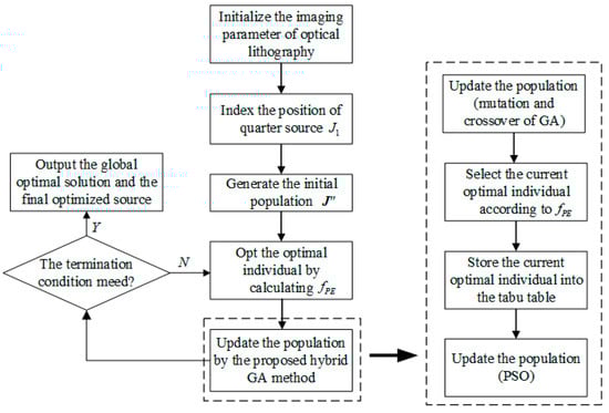
Figure 3.
Flowchart of the optimization of the source. The optimization flow of the proposed hybrid GA method is adequately described inside the dotted boxes.
Because of the complexity of imaging models for optical lithography, it is difficult to utilize a traditional GA to attain the optimal source. Although GAs have a great convergence effect in iterative processes for simple optimization models, premature convergence can cause the merit function to fall into a local optimum in a complicated model. To improve the performance of the optimization model based on a GA, optimization strategies—the method of updating the population in PSO and the search method in TS—were inserted into the GA to overcome the local optimal conditions. In the proposed hybrid algorithm, the GA executes mutation and crossover operations to revise the current population in each iteration. The updated population can be calculated with the following formulas in the mutation process.
In Equation (7), represents a random increment that can be generated with a random function in different iteration loops. and are the current iteration number and the total number of iterations, respectively. The increase and decrease in individuals with respect to the magnification in can be, respectively, implemented with Equations (8) and (9). represents the units of individuals in the row and column, where and . In addition, it is necessary for the crossover operation of the GA to be employed to enlarge the search range in order to enhance the convergence abilities. The node to be crossed in can be found with
where represents a mathematical function that implements a rounding operation to generate the nearest integer. The exchanged part of the individual can be decided according to the position . Hence, the population can be updated with the mutation and crossover operations in the procedure of the GA. The optimal individual in the current iteration can be selected from , and it is recorded on the tabu list. It is significant to establish the list in order to enhance the search capabilities and break away from local optima. The tabu list can store the number of individuals, and it is calculated with the following formula.
To ensure the global conditions in the complex SO model, PSO is employed to enlarge the update scope of the variates. The strategy of using a weight coefficient based on the hyperbolic tangent is proposed to manipulate the speed of updating the variates, which is also varied in a different loop, and this is denoted by the following:
In Equation (13), represents the weight coefficient in the iteration, is the hyperbolic tangent function, and is the constant. and are, respectively, the maximum and minimum weight coefficients, which are set before the iteration starts. Equations (14) and (15) indicate the strategy of updating the individual in PSO. represents the search speed of the variate for the individual in the iteration. and are the current optimal value and the global optimal value, respectively. and are both learning factors and are constants.
3. Simulations
In this section, several simulation results involving aerial images with optimized sources are provided to verify the superior performance in optical lithography after utilizing the pixelated SO method based on the proposed hybrid GA approach. An imaging model for optical lithography is established, and this was based on a 193 nm immersion lithography system in the 45 nm node. In this model, the numerical aperture of the projection objective was 1.25. The annular illumination mode was employed for the imaging source in the initial stage to provide the initial aerial image, where and . Furthermore, this pixelated annular source was set as a matrix. To generate the resistance pattern, a sigmoid function was utilized in the optimization model, where and .
Figure 4 illustrates the initial source and mask employed to accomplish the imaging process for optical lithography. For Figure 4a–c, the value of the pixels in the white region was set to 1; otherwise, their value was 0. To ensure the continuous variation of the valid pixels and to reduce the dispersion degree of the annular source in the optimization process, the blurred source shown in Figure 4b could be generated by performing a fuzzy operation on the binarized source in Figure 4a. To verify the optimization performance of the pixelated SO based on the proposed method, two patterns were employed as input feature patterns to form an aerial image for optical lithography; these were the horizontal block pattern (#M1) and the periodic optical grating pattern (#M2). They could be represented as real matrices with the size , where .
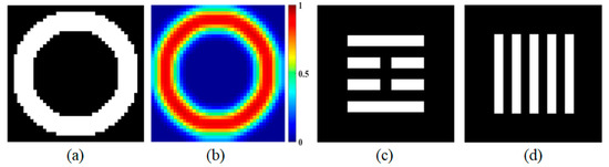
Figure 4.
The initial source and the mask used in the imaging process. (a) The pixelated annular source; (b) the blurred source; (c) the horizontal block pattern (#M1); (d) the periodic optical grating pattern (#M2).
In these simulations, the proposed pixelated-SO-based method was carried out in three runs to evaluate its optimization performance. In each simulation, there were 150 iterations to optimize the intensity distribution of the lithographic source for the horizontal block pattern (#M1) and the periodic optical grating pattern (#M2). The final lithographic source, which was defined as the optimal source, was used as the input condition to complete the lithographic imaging process and to attain the resistance pattern. These simulation results are shown in Figure 5. Rows 1 and 2 present the source optimization results and the resistance patterns from three runs. The intensity distributions of the optimal sources for (#M1) and (#M2) are, respectively, displayed in the first and third columns of Figure 5. Their resistance patterns are, respectively, shown in the second and fourth columns, and they were obtained by utilizing the optimal source. In these optimized sources, the intensity distributions for #M1 were closer to a vertical quadrupole illumination mode. This is because, in the vertical direction, the pattern had a similar periodic grating structure to that of the vertical bipolar illumination mode. Horizontally, the middle area lacked pattern information for the horizontal illumination mode. For #M2, a 45-degree quadrupole illumination mode was more necessary for ensuring better image quality in the imaging process for optical lithography due to the periodic horizontal grating structure of the array.
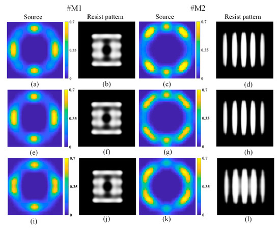
Figure 5.
The optimized source and resistance patterns obtained with the proposed method. (a,e,i) are the optimization results for the source with #M1; (c,g,k) are the optimized source results with #M2; (b,f,j) are the resistance patterns with #M1 for the optimal source as the input condition; (d,h,l) are the resistance patterns with #M2 for the optimal source as the input condition. From the top row to the bottom, these are the results of three runs of the simulation.
Figure 6 shows the simulation results when using two other methods with 150 iterations; these were a hybrid GA based on TS (TS-GA) and a method that combined the GA with the optimization strategy of PSO (PSO-GA). Figure 6a,e show the final source shapes for #M1 when utilizing TS-GA and PSO-GA, respectively. Similarly, Figure 6c,g were, respectively, achieved by using these two methods for #M2. Compared with the simulation results for the proposed method, the results shown in Figure 6 are not satisfactory. Although the tendencies of the source shapes were similar, there was a significant decrease in the intensity value for TS-GA and PSO-GA. Furthermore, it was obvious that the quality of the resistance patterns was not high enough when these optimal sources were employed as the lithographic imaging conditions. It was verified that the search process fell into a local optimum in the optimization process for these two methods. Furthermore, the convergence curves in the iterative process for these simulations are shown in Figure 7. Although the PEs obtained with PSO-GA decreased faster than those obtained with TS-GA for these two patterns before 25 iterations, those obtained with PSO-GA fell into a local optimum earlier than the others. This was because PSO had high efficiency early in the optimization process, which improved the overall optimization efficiency of PSO-GA. In comparison with these two simulation results, TS-GA had stronger convergence stability. On the contrary, the proposed method not only had a stable convergence efficiency, but also had a stronger optimization ability than that of the other two methods for PEs with #M1 and #M2. Hence, the proposed method had enhanced search capabilities and higher convergence efficiency.
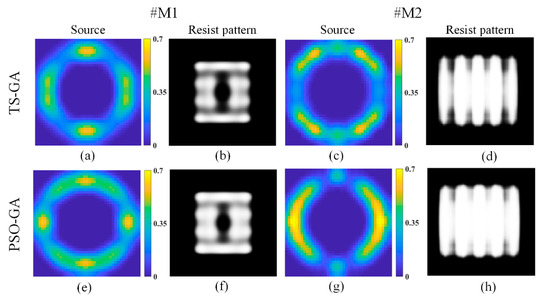
Figure 6.
The optimized source and resistance patterns obtained with two other methods. (a–d) and (e–h) present the simulation results from TS-GA and PSO-GA, respectively; (a,c,e,g) are the source optimization results; (b,d,f,h) are the resistance patterns with the optimal source as the input condition in these simulations.
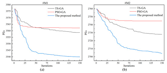
Figure 7.
The convergence curves in the iterative process. (a,b) are the convergence tendencies when optimizing the lithographic source according to #M1 and #M2, respectively.
4. Conclusions
In this study, a high-efficiency hybrid GA method was proposed to generate the optimal intensity distribution of a source in the imaging process for optical lithography in order to achieve an acceptable image quality. To improve the optimization efficiency in the SO model, a GA was used as the main body in the optimization model. Meanwhile, to expand the search scope, an update strategy using PSO was employed to modify the values of variates in the population. In this complex optimization model, the tabu list method was utilized to record the individuals that appeared, making it possible to break away from local optima to avoid the premature convergence of the optimization model. Moreover, it was significantly important for the pattern errors (PEs) to be defined as a merit function for selecting the current optimal individual of the population. To reduce the computational complexity, a quarter region of the source was used as the optimization target, and it could be flipped to form the integral source with a mirror operation. Furthermore, to improve the convergence efficiency, two other methods were employed to optimize the lithographic source shape, namely, TS-GA and PSO-GA. The simulation results confirmed that the proposed SO method based on the hybrid GA had efficient optimization performance when improving the image quality during the imaging process for optical lithography.
Author Contributions
Simulation design, J.L.; methodology, J.L. and D.Y.; investigation, J.L., J.Z. and H.S.; data curation, J.L., D.Y. and J.Z.; writing—original draft preparation, J.L., D.Y. and J.W.; writing—review and editing, J.L., S.H. and J.W. All authors have read and agreed to the published version of the manuscript.
Funding
The work was supported by the National Key Research and Development Plan (2021YFB3200204), the National Natural Science Foundation of China (NSFC) under grant nos. 61604154, 61875201, 61975211, and 62005287, the Youth Innovation Promotion Association of the Chinese Academy of Sciences (2021380), and the project of the Western Light of Chinese Academy of Science.
Institutional Review Board Statement
Not applicable.
Informed Consent Statement
Not applicable.
Data Availability Statement
Not applicable.
Conflicts of Interest
The authors declare no conflict of interest.
References
- Wong, A.K.-K. Optical Imaging in Projection Microlithography; SPIE Optical Engineering Press: Bellingham, WA, USA, 2005; ISBN 978-0-8194-5829-2. [Google Scholar]
- Levinson, H.J. Principles of Lithography, 3rd ed.; SPIE Press Monograph: Bellingham, WA, USA, 2010; ISBN 978-0-8194-8324-9. [Google Scholar]
- Wong, A.K. Resolution Enhancement Techniques in Optical Lithography; SPIE: Bellingham, DC, USA, 2001; ISBN 978-0-8194-7881-8. [Google Scholar]
- Schellenberg, F.M. Resolution Enhancement Technology: The Past, the Present, and Extensions for the Future. In Proceedings of the SPIE—The International Society for Optical Engineering, Santa Clara, CA, USA, 28 May 2004; p. 1. [Google Scholar]
- Liebmann, L.W. Resolution Enhancement Techniques in Optical Lithography: It’s Not Just a Mask Problem. In Proceedings of the Photomask and Next Generation Lithography Mask Technology VIII, Kanagawa, Japan, 5 September 2001; p. 23. [Google Scholar]
- Isoyan, A.; Melvin, L.S. Optical Proximity Correction Using Holographic Imaging Technique. J. Vac. Sci. Technol. B 2014, 32, 9. [Google Scholar] [CrossRef]
- Shen, Y.; Peng, F.; Zhang, Z. Efficient Optical Proximity Correction Based on Semi-Implicit Additive Operator Splitting. Opt. Express 2019, 27, 1520. [Google Scholar] [CrossRef] [PubMed]
- Hakko, M.; Suzuki, K. Resolution Enhancement with Source-Wavelength Optimization According to Illumination Angle in Optical Lithography. J. Micro/Nanolithogr. MEMS MOEMS 2020, 19, 043201. [Google Scholar] [CrossRef]
- Ma, X. Resolution Enhancement Optimization Methods in Optical Lithography with Improved Manufacturability. J. Micro/Nanolithogr. MEMS MOEMS 2011, 10, 023009. [Google Scholar] [CrossRef]
- Ma, X.; Arce, G.R. Pixel-Based Simultaneous Source and Mask Optimization for Resolution Enhancement in Optical Lithography. Opt. Express 2009, 17, 5783. [Google Scholar] [CrossRef]
- Jiang, J.; Mei, Q.; Li, Y.; Liu, Y. Illumination System with Freeform Fly’s Eye to Generate Pixelated Pupil Prescribed by Source-Mask Optimization in Extreme Ultraviolet Lithography. Opt. Eng. 2017, 56, 065101. [Google Scholar] [CrossRef]
- Lv, W.; Liu, S.; Wu, X.; Lam, E.Y. Illumination Source Optimization in Optical Lithography via Derivative-Free Optimization. J. Opt. Soc. Am. A 2014, 31, B19. [Google Scholar] [CrossRef]
- Ma, X.; Wang, Z.; Lin, H.; Li, Y.; Arce, G.R.; Zhang, L. Optimization of Lithography Source Illumination Arrays Using Diffraction Subspaces. Opt. Express 2018, 26, 3738. [Google Scholar] [CrossRef]
- Kuo, H.-F.; Wu, W.-C. Forming Freeform Source Shapes by Utilizing Particle Swarm Optimization to Enhance Resolution in Extreme UV Nanolithography. IEEE Trans. Nanotechnol. 2015, 14, 322–329. [Google Scholar] [CrossRef]
- Zimmermann, J.; Gräupner, P.; Neumann, J.T.; Hellweg, D.; Jürgens, D.; Patra, M.; Hennerkes, C.; Maul, M.; Geh, B.; Engelen, A.; et al. Generation of Arbitrary Freeform Source Shapes Using Advanced Illumination Systems in High-NA Immersion Scanners. In Proceedings of the SPIE—The International Society for Optical Engineering, San Jose, CA, USA, 11 March 2010; p. 764005. [Google Scholar]
- Peng, Y.; Zhang, J.; Wang, Y.; Yu, Z. High Performance Source Optimization Using a Gradient-Based Method in Optical Lithography. In Proceedings of the 2010 11th International Symposium on Quality Electronic Design (ISQED), San Jose, CA, USA, 22–24 March 2010; pp. 108–113. [Google Scholar]
- Jia, N.; Lam, E.Y. Pixelated Source Mask Optimization for Process Robustness in Optical Lithography. Opt. Express 2011, 19, 19384. [Google Scholar] [CrossRef]
- Li, J.; Lam, E.Y. Robust Source and Mask Optimization Compensating for Mask Topography Effects in Computational Lithography. Opt. Express 2014, 22, 9471. [Google Scholar] [CrossRef]
- Ma, X.; Han, C.; Li, Y.; Dong, L.; Arce, G.R. Pixelated Source and Mask Optimization for Immersion Lithography. J. Opt. Soc. Am. A 2013, 30, 112. [Google Scholar] [CrossRef]
- Jia, N.; Lam, E.Y. Stochastic Gradient Descent for Robust Inverse Photomask Synthesis in Optical Lithography. In Proceedings of the 2010 IEEE International Conference on Image Processing, Hong Kong, China, 26–29 September 2010; pp. 4173–4176. [Google Scholar]
- Ding, M.; Niu, Z.; Zhang, F.; Zhu, L.; Shi, W.; Zeng, A.; Huang, H. Gradient-Based Source Mask and Polarization Optimization with the Hybrid Hopkins–Abbe Model. J. Micro/Nanolithogr. MEMS MOEMS 2020, 19, 033201. [Google Scholar] [CrossRef]
- Whitley, D. A Genetic Algorithm Tutorial. Stat. Comput. 1994, 4, 65–85. [Google Scholar] [CrossRef]
- Haldurai, L.; Madhubala, T.; Rajalakshmi, R. A Study on Genetic Algorithm and Its Applications. Int. J. Comput. Sci. Eng. 2016, 4, 6. [Google Scholar]
- Sortrakul, N.; Nachtmann, H.L.; Cassady, C.R. Genetic Algorithms for Integrated Preventive Maintenance Planning and Production Scheduling for a Single Machine. Comput. Ind. 2005, 56, 161–168. [Google Scholar] [CrossRef]
- Zhang, J.; Zhang, X.; Zhang, J. Image Segmentation Method Based on Improved Genetic Algorithm and Fuzzy Clustering. Adv. Mater. Res. 2010, 143–144, 379–383. [Google Scholar] [CrossRef]
- Hong, T.-P.; Chen, C.-H.; Wu, Y.-L.; Lee, Y.-C. A GA-Based Fuzzy Mining Approach to Achieve a Trade-off Between Number of Rules and Suitability of Membership Functions. Soft Comput. 2006, 10, 1091–1101. [Google Scholar] [CrossRef]
- Fühner, T.; Erdmann, A.; Farkas, R.; Tollkühn, B.; Kókai, G. Genetic Algorithms to Improve Mask and Illumination Geometries in Lithographic Imaging Systems. In Applications of Evolutionary Computing; Lecture Notes in Computer Science; Raidl, G.R., Cagnoni, S., Branke, J., Corne, D.W., Drechsler, R., Jin, Y., Johnson, C.G., Machado, P., Marchiori, E., Rothlauf, F., et al., Eds.; Springer: Berlin/Heidelberg, Germany, 2004; Volume 3005, pp. 208–218. ISBN 978-3-540-21378-9. [Google Scholar]
- Li, Y.; Yu, S.-M.; Li, Y.-L. Intelligent Optical Proximity Correction Using Genetic Algorithm with Model- and Rule-Based Approaches. Comput. Mater. Sci. 2009, 12, 65–76. [Google Scholar] [CrossRef]
- Hong, L.; Fan, J.; Tritchkov, A.; Word, J.; Zhang, D. Inverse Lithography Recipe Optimization Using Genetic Algorithm. In Proceedings of the Optical Microlithography XXXI, San Jose, CA, USA, 27 February–1 March 2018; p. 53. [Google Scholar]
- Deb, K.; Pratap, A.; Agarwal, S.; Meyarivan, T. A Fast and Elitist Multiobjective Genetic Algorithm: NSGA-II. IEEE Trans. Evol. Comput. 2002, 6, 182–197. [Google Scholar] [CrossRef]
- Yuan, Q.; Qian, F. A Hybrid Genetic Algorithm for Twice Continuously Differentiable NLP Problems. Comput. Chem. Eng. 2010, 34, 36–41. [Google Scholar] [CrossRef]
- Dziwinski, P.; Bartczuk, L. A New Hybrid Particle Swarm Optimization and Genetic Algorithm Method Controlled by Fuzzy Logic. IEEE Trans. Fuzzy Syst. 2020, 28, 15. [Google Scholar] [CrossRef]
- Drezner, Z.; Misevičius, A. Enhancing the Performance of Hybrid Genetic Algorithms by Differential Improvement. Comput. Oper. Res. 2013, 40, 1038–1046. [Google Scholar] [CrossRef]
- Ma, X.; Arce, G.R. Computational Lithography; Wiley Series in Pure and Applied Optics; Wiley: Hoboken, NJ, USA, 2010; ISBN 978-0-470-59697-5. [Google Scholar]


Disclaimer/Publisher’s Note: The statements, opinions and data contained in all publications are solely those of the individual author(s) and contributor(s) and not of MDPI and/or the editor(s). MDPI and/or the editor(s) disclaim responsibility for any injury to people or property resulting from any ideas, methods, instructions or products referred to in the content. |
© 2023 by the authors. Licensee MDPI, Basel, Switzerland. This article is an open access article distributed under the terms and conditions of the Creative Commons Attribution (CC BY) license (https://creativecommons.org/licenses/by/4.0/).