1. Introduction
Recently, a new bio-inspired vision sensor, the event camera [
1], has emerged and broke the limitation of the standard camera working principle and frame rate. Different from frame of traditional cameras, the event camera could respond to pixel-wise brightness changes in the scene asynchronously and independently.
Due to the low temporal resolution, high latency and highly redundant data, the frame-based camera performs poorly in complex scenes such as high-speed motion scenes and suffers from missed and incorrect corner detection tasks in complex scenes due to the motion blur and the low dynamic range of its output.
With the unique imaging mechanism, event cameras are low latency (in the order of microseconds), have low power consumption and have a very high dynamic range (120 dB) and very high temporal resolution. As such, event cameras can capture the scene changing rapidly without motion blur and effectively filter the background, which has brought about a new approach to machine vision and artificial intelligence.
Event cameras have been widely applied to various visual tasks such as optical flow estimation [
2], simultaneous localization and mapping (SLAM) [
3] and feature detection [
4]. Feature detection is a basic and core component in machine vision tasks such as robot vision servoing [
5] and autonomous driving [
6]. As a special feature, corners show drastic grey changes in many directions, which makes them easily distinguishable from the neighbouring pixels. The shortcoming of traditional cameras is that they often result in missed and false detections of corners, introducing errors to higher-level vision tasks. Event cameras tend to show better performance in complex senses due to their characteristics. Therefore, how to extract corners from asynchronous event streams quickly and accurately is still an open problem. The main existing event-based corner detection algorithms are template-based methods [
7], gradient-based methods [
8] and hybrid methods [
9].
High-resolution event cameras are helpful to obtain more detailed features in these tasks, but the existing higher-resolution event cameras, such as CeleX-V (1280 × 800) [
10] and Samsung’s DVS Gen4 (1280 × 960) [
11], can generate more than 10 million events per second, dozens of times more events than DAVIS240C which used in event camera datasets [
12]; therefore, realizing real-time processing is still a problem.
Therefore, to obtain higher performance in complex scenes, it is necessary to explore a more effective method to remove redundant and noisy events as much as possible to reduce computational cost and save computing resources. To address the aforementioned problem, we propose an improved event-based corner detector and design a novel filter and a new local Surface of Active Events (SAE) representation method. The filter uses a double-threshold to remove redundant and noisy events, which is able to significantly improve throughput while maintaining performance. The proposed local SAE representation is a modification of the original Sigmoid function, which is computationally efficient and better reflects the spatio-temporal distribution of events than existing representations. We evaluate our method on public datasets and achieve better performance.
The main contributions of this paper are the following:
A simple and effective event-based double threshold filter that reduces redundant and noisy events from the events stream effectively which has better performance than the previous filter and is suitable for the existing event-based corner detector;
An efficient local SAE representation method called -SAE which has lower computation and clearer spatio-temporal distribution;
An asynchronous corner tracker which verifies the effectiveness of our detector.
The remainder of the paper is organized as follows. In
Section 2, we present the related work about event-based feature extraction.
Section 3 describes our proposed detector in detail. In
Section 4, we describe the experimental design and evaluation results. In
Section 5, we present a summary and look forward to future work.
2. Related Work
Since the development of event cameras, several works have been dedicated to extracting features from event streams and detecting and tracking features such as lines [
13,
14] and circles [
15]. As a special feature, corner detection has also attracted many researchers.
2.1. Event Representation
For event-based corner detection tasks, SAE is a spatial-temporal representation of event-based data, which is used to distinguish new events from old events. SAE can be represented as a mapping function
that maps pixels to its corresponding timestamps of the latest event in
, shown as Equation (
1).
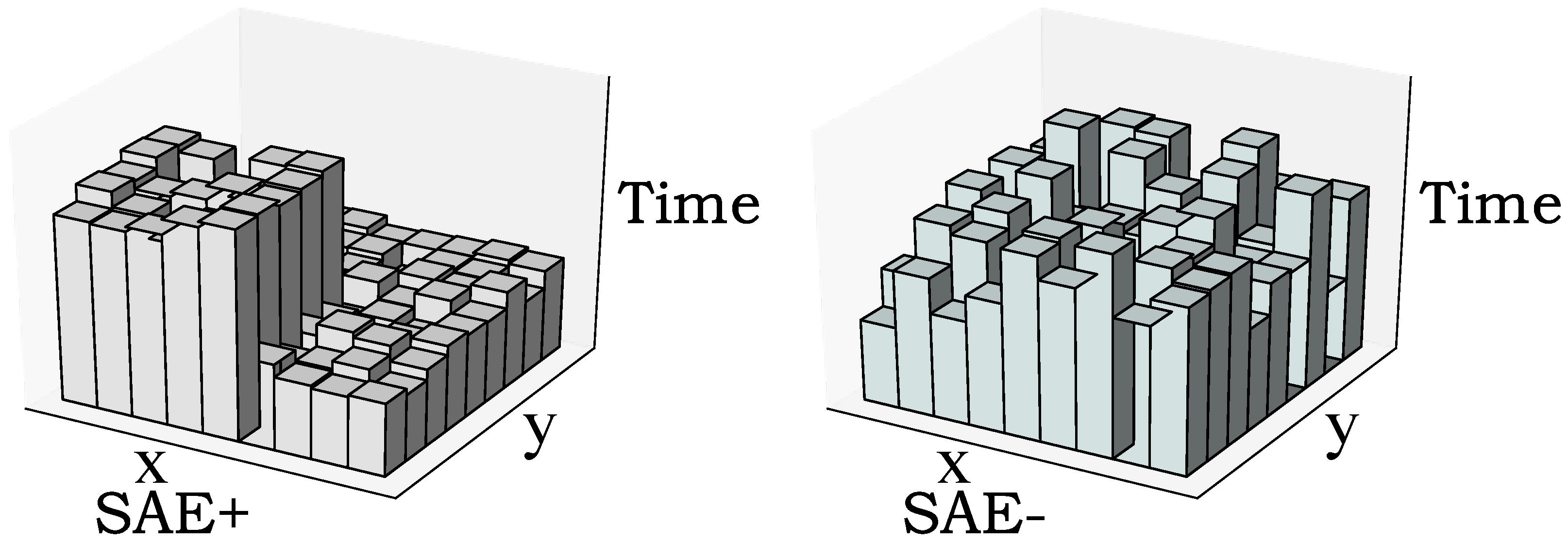
The mapping of the whole scene is global SAE, which can be used for global perception. The mapping of local areas is called local SAE, which is used to extract local features. A typical SAE is shown in
Figure 1, where positive polarity events are updated in SAE+ and negative polarity events are updated in SAE−.
Ideally, to obtain clearer gradient information, there should be a significant gradient between the timestamps of the new and old events on the local SAE. To better distinguish between new and old events, Li et al. [
9] and Mohamed et al. [
16] took a binary SAE and the latest
timestamps were assigned to 1 and the rest to 0. In addition, there are other SAE constructions such as min-max normalization [
17] and exponential decay [
18].
2.2. Frame-Based Corner Detector
Currently, frame-based corner detectors have been widely used in various fields. For example, Harris [
19] detects corners by detecting grey-level changes around pixels. The core idea is that a small movement of the corner in any direction will cause great changes in the direction of the gradient in the selected area. That is, the pixel is a corner if the gradient of the grey image is a local maximum. As one of the most popular frame-based corner detectors, it has been widely used in chessboard calibration, image registration and others. Shi et al. [
20] proposed the Shi-Tomasi detector, which modified the score function of the Harris algorithm and obtained a better result.
The Smallest Univalue Segment Assimilating Nucleus (SUSAN) [
21] detector uses a circular sliding window template in which the grey value of each pixel within the sliding window is compared with the central pixel. If the difference in grey value between two pixels is less than a threshold, the pixel is identified as having a similar grey value to the central pixel. The area of pixels that meet this condition is called the Univalue Segment Assimilating Nucleus (USAN). The value of the USAN is then calculated and compared to a given threshold, and if the pixel’s USAN value is less than the threshold, it is identified as a SUSAN corner. This method has a lower number of parameters and is therefore more computationally efficient and more robust to noise.
Feature from Accelerated Segment Test (FAST) [
22] draws a circle with a radius of 3 pixels around the selected centre pixel, and there are 16 pixels in the circle. The differences between these pixels and the selected centre pixel are calculated; if there are consecutive
n (generally
n = 12) pixels and the absolute value of the difference between the grey value of the centre pixel is greater than the threshold, the centre pixel is identified as the FAST corner feature.
2.3. Event-Based Corner Detector
The first event-based asynchronous corner detector uses plane fitting to detect corners and event characteristics [
23]. Most of the subsequent corner detectors are based on Surface of Active Events (SAE) [
24], which can effectively reflect the spatio-temporal information around the events. There are two main types of event-based corner detection algorithms, which are template-based (e.g., eFAST [
7] and Arc* [
25]) and gradient-based (e.g., eHarris [
8]). They have their own strengths and weaknesses. In contrast, the template-based detector can detect corners faster but with low accuracy, while the gradient-based detector is more accurate but very time-consuming and difficult to detect in real-time. Therefore, the most popular method is to combine the two types of algorithms and take a trade-off.
2.3.1. Template-Based Corner Detector
The most representative template-based corner detector is eFAST [
7], which detects the corners by finding continuous arcs on two circles, respectively. If the pixels which meet the conditions in each circle form a continuous arc, and the length of the arc is within the given range, the centre pixel is considered a corner. However, the corner must be less than 180 degrees to prevent incorrect detection results.
Alzugaray proposed an Arc* detector [
25] which overcomes the defect of eFAST that fails to detect angles greater than 180 degrees. This was the first time a filter was used on Arc* to remove redundant events from the event stream in corner detection tasks. In their approach, the timestamps were stored in two global SAEs—the latest SAE and the filtered SAE. This filter removes a large number of redundant events and improves the throughput. This corner detector can detect corners more than 4× faster than eFAST and 50× faster than eHarris.
2.3.2. Gradient-Based Corner Detector
eHarris [
8] is the first event gradient-based corner detector which generates local SAE for each pixel in the image plane and stores timestamps with a size of 9 × 9. The normalized timestamps in the local SAE are used to calculate the local gradient. However, once a new event arrives, each local SAE containing the pixels corresponding to this event needs to be updated, which is time-consuming. Li et al. [
9] proposed G-eHarris, in which the timestamps are stored on a global SAE and then extracted to the local SAE from the global SAE when needed, which greatly improves the efficiency of eHarris.
2.3.3. Hybrid Corner Detector
In contrast, a template-based detector can detect corners faster, but the accuracy is low, while a gradient-based detector has higher accuracy, but it is very time-consuming and difficult to realize real-time detection. To achieve a better trade-off between throughput and accuracy, researchers combined two types of methods. Li et al. [
9] proposed the first hybrid event-based corner detector called FA-Harris in which after processing the original event stream with a template-based detector, events that are completely impossible to be corners are discarded. Then, a gradient-based method was used to accurately locate the position. Similarly, the same idea is also applied in [
16,
26] to improve corner detection quality through multi-layer structure; firstly, redundant events are removed by the filter, then the template-based method is used to detect quickly, and finally a gradient-based method is used to refine the detection.
3. Materials and Methods
Inspired by [
9,
16], to achieve a better trade-off between throughput and accuracy, we propose an improved hybrid method. First, we use a double-threshold filter to remove redundant and noisy events, then we use a template-based method to locate corners faster and a modified gradient-based method with the proposed
-SAE to provide better corner detection results. By combining the two types of methods, a trade-off can be achieved between throughput and accuracy. The pipeline is shown in Algorithm 1, and a more intuitive flow diagram is shown in
Figure 2.
| Algorithm 1 The DTFS-eHarris Algorithm. |
![Applsci 13 05761 i001]() |
3.1. Event Generation Model
Each pixel of the event camera senses changes in brightness in the scene independently and asynchronously [
27]. If a pixel senses a change in brightness that exceeds a predetermined threshold, an event is generated for that pixel. The event is output in the Address Event Representation (AER) format and can be expressed as
, where
x and
y represent the coordinate position of the pixel generating the event,
t is the time stamp of the event, and
p is the polarity of the event (i.e., is either 1 or −1).
The mathematical model for event generation is shown in Equation (
2), where
is the latent image, representing the instantaneous brightness of the pixel at coordinates
at the current moment, and
is the instantaneous brightness at the pixel location when the previous event was triggered [
28]. The instantaneous brightness is calculated by taking the logarithm of the instantaneous brightness values at both moments. If the intensity of the increase in brightness exceeds the threshold, a positive event is generated and the value of
p is 1. Conversely, if the intensity of the decrease in brightness exceeds the threshold, a negative event is generated and the value of
p is −1, as shown in Equation (
3), where
c denotes a predetermined threshold value and
d denotes the brightness change value.
When a new event is triggered at that pixel, should be updated to the instantaneous brightness at the time of the latest triggered event.
3.2. Double Threshold Filter
The main purpose of the double-threshold filter is to reduce redundant events and noise. This step can significantly reduce the number of events to be detected, greatly improve the real-time performance of the algorithm and improve the quality of corner detection.
A sudden and drastic brightness change would generate multiple events in one pixel almost instantaneously according to Equation (
4). Due to hardware limitations, however, there exists a minimum amount of time between consecutive events triggered at the same pixel. However, such time-intensive events are not necessary for corner detection tasks.
The time filter proposed in [
25] removes redundant events in corner detection tasks. Events are divided into two parts by a single threshold. Only events whose timestamps over the threshold will be detected, other events will be treated as redundant events.
However, this method can only remove redundant events through a single threshold and can not remove filter noisy events. Therefore, we propose a double threshold filter to remove redundant and noisy events. Timestamps are stored in two global SAE,
and
, the SAE
is defined as
, where
is the timestamp of the latest event triggered at the pixel location
,
is defined as
, and
is the reference time.
will be updated for every event and
will be updated only if the previous event in the same pixel was not triggered within the time window [
,
], as shown in Equations (
5) and (
6).
Only the events in are considered in subsequent processing, the rest of the events are treated as redundant events or noise.
3.3. Corner Pre-Detection
To ensure real-time processing, a template-based method [
25] is used to select corners first. This algorithm is currently the largest throughput corner detection algorithm which is used to quickly filter corners. For each coming event which has been updated in
, a local SAE (denote as
) can be extracted centred on the event with a size 9 × 9. Then, it focuses only on the pixels on two concentric circles of radius 3 (blue) and 4 (green), as shown in
Figure 3.
The location of a new event is used as the centre of a circular mask of a predefined radius. This circular mask defines a set of locations, the value of which we retrieve in SAE
, using the same polarity as the new event, and create a circular set of elements
C. We initialize the arc of the newest elements
with the newest element in
C and a pair of supporting elements in the adjacent clockwise (CW) and counter clockwise (CCW) positions;
and
and
are its complementary arcs, as shown in
Figure 3. The arc
starts from the newest timestamp until all values in
are greater than others. The length thresholds of continuous arcs
and
are [3, 6] for the inner circle and [4, 8] for the outer circle, respectively. The centre pixel of the local SAE will be considered as a corner if the length of any arc is within the threshold range.
After corner pre-detection, events that can not be a corner at all are discarded. The selected events will be further detected.
3.4. Corner Detection Refinement
In this step, the local SAE will be extracted from the global SAE
and then be normalized. For corner detection tasks, local SAE is usually expected to have significant gradient information between new and old events. Li et al. [
9] and Mohamed et al. [
16] sorted the timestamps on the local SAE, assigning the latest 25 timestamps to 1 and the rest to 0. In addition, there are other SAE constructions, such as min-max normalization [
17] and exponential decay [
18]. However, those methods completely ignore the time interval among events, which can not well reflect the temporal and spatial distribution of local SAE. Therefore, we propose a new normalization method that uses the Sigmoid function to normalize the timestamp information.
Firstly, the timestamps stored in global SAE are transformed from the range of (0,
) to a value between [0, 1]. To obtain clearer gradient information, the timestamp of the centre pixel on
(the latest event) is used as the reference time and calculates relative time with the rest of the events
, as shown in Equation (
7). For the normalization of local SAE, we do not expect the data to be distributed evenly. The newer the event, the closer we expect the value to be 1 and for the older event, we expect it to be close to 0. That is, for the time difference stored in local SAE (as shown in
Figure 4a), the closer to 0, the closer the normalized value should be to 1; however, the value is close to 0.
where
is the relative time,
indicates the timestamp of the middle pixel and
denotes the timestamp at the position
. Inspired by the activation function of machine learning, we improved the Sigmoid function to obtain the nonlinear distribution. The proposed normalized method is shown in Equation (
8) and
Figure 5, named
.
where two hyper-parameters
and
are introduced into the original Sigmoid function, which is fine-tuned to adjust normalized results and can be changed based on the complexity of scenes. It has lower computation and clearer spatio-temporal distribution than binary normalization [
9], min-max normalization [
17] and exponential decay [
18].
Figure 6 presents the trends of
with multi-parameters; in a word, smaller alpha and bigger beta are preferred for time-dense events, and vice versa. For this experiment, we set
= 0.005 and
= 300 manually. It is obvious that when the relative time is close to 0, the function value is close to 1; with the increase in relative time, the function value has a sharp decline.
Figure 4b is the result of
, and it is obvious that the results of
Figure 4b,d are the best and our method has lower computation.
Then, the Harris [
19] detector is used on
which is normalized by the
, and the score is calculated by Equations (
9) and (
11)
where
and
are the gradients of the patch in the
x and
y directions, respectively, and
is a Gaussian filter with
, shown as Equation (
10).
If both eigenvalues
and
in matrix
M are large, a corner event is probable. The Harris score is calculated by Equation (
11).
where
k is an empirical constant and is commonly set at 0.04. If the Harris score is greater than the preset threshold, the detected event will be classified as a corner event.
3.5. Event Based Corner Tracker
Our method associates the corner events based on proximity under the assumption that the corner detection is accurate. The proposed tracker split the events into the parent node and leaf node, denoted as and . A leaf node plane (denote as ) is constructed to store spatio-temporally for every existing trajectory. A coming event will be divided into an existing feature or a new feature and will be updated. Then, a spatio-temporal window can be created for each trajectory by distance threshold and time threshold .
If the event is not in any existing spatio-temporal window, it will be treated as the first event of a new trajectory. The pipeline is shown in Algorithm 2.
| Algorithm 2 The Tracker Algorithm. |
![Applsci 13 05761 i002]() |
4. Experiments and Results
Our method is evaluated on the public Event Camera Datasets [
12], which provides asynchronous event stream and its corresponding intensity images (frame-based) captured on the same chip at the same time. The scenarios we used to evaluate are shown in
Figure 7.
The method proposed in this paper only works on event stream, and intensity images are used to extract the ground truth of corners. Our method is evaluated on shapes, dynamic, poster and boxes scenes, which cover high, medium and low textures and each scene contains three forms of movement.
We compare the performance of our work with eFAST, eHarris, Arc* and FA-Harris, using the original implementation provided by the authors. We evaluate both G-eHarris and eFAST with the proposed double threshold filter, denoted as G-eHarris† and eFAST†, respectively. To check the performance of our proposed double threshold filter, we modify the single threshold filter of Arc* and FA-Harris into a double threshold filter; the new version is called Arc*† and FA-Harris†.
For the event-based corner detector, there are four important evaluation metrics, which are Throughput, Reduction Rate, False Positive Rate and Accuracy; we use the same definition in [
9,
25].
All experiments were run on a laptop equipped with an Intel i5-5200U CPU with 2.20 GHz and 12GB of RAM and implemented using single-threaded C++.
4.1. Ground-Truth Collection
Similar to the method in [
7,
25], a Harris detector [
19] and LK tracker [
29] are used to collect the ground truth on the intensity image. For two adjacent intensity images, we use the original Harris detector to detect corners on the first image with the shortest distance of 5, and then take the LK tracker to track them on the second image. Considering that new corners may appear in the second image, after tracking, we continue to detect new corners on the second image. If the distance between detected new corners and tracked corners is less than 5 pixels in the second image, the two corners are considered the same corner. Then all corners will be tracked continuously.
The frame rate of the intensity image is about 25 Hz. We approximately consider that the corners move in a uniform linear motion between two adjacent images. Then, based on the segment generated by the motion of this corner (denote as
l), as shown in
Figure 8, we can construct two concentric cylinders and calculate the distance from the event corners to
. If the distance is less than or equal to 3.5 pixels, we consider it as true event corner and label it as the ground truth. For an event whose distance is greater than 3.5 but less than 5, we consider it to be a wrong corner and label it as a false event corner.
4.2. Qualitative Analysis
In
Table 1, we report the Reduction Rate (Red.) of our detector with other SOTA detectors as a percentage. The Reduction Rate indicates the ability to reduce the event stream to a feature stream [
7]. Our work shows the best performance.
Figure 9 shows the detection quality comparison on
poster scene, which is the most complex scene in this experiment. We show the results between two adjacent frames. Our method outperforms all other methods and has lower noisy detection. As shown in
Table 1, our work reduces the most events than other detectors. The main issue of the template-based detector in
Figure 9e,f is that many false corners are mistakenly detected, e.g., the bottom-right of the scene.
4.3. Real-Time Performance
As event cameras are often used in highly dynamic scenes, detection efficiency is important for event-based corner detection methods and data throughput is an important real-time performance evaluation metric.
Table 1 shows the real-time performance of different corner detection algorithms, incorporating the average time required to process a single event (μs) and the maximum number of events that can be processed per second in millions of events per second (Meps). The first three rows in the table are for the normal detection method and the last two rows are for the hybrid detection method. Our method improves by about 20% faster than FA-Harris and 4× faster than eHarris†. However, Arc* is 3× faster than ours since we apply the gradient-based method to refine corners for higher accuracy.
4.4. Accuracy Performance
The False Positive Rate (FPR) and Accuracy are reported in
Table 2 and
Table 3, respectively, using the same definition as [
9,
25]. For the ground-truth corners, the trajectories of the real corners have been obtained using the Harris and LK algorithms in
Section 4.1. The confusion matrix is shown in
Table 4.
The TPR is calculated as Equation (
12), the FPR is calculated as Equation (
13) and the Accuracy is calculated as Equation (
14).
The proposed method shows the best performance in FPR and better performance in Accuracy. With the increase in scene complexity, the advantage gradually expands, which means that our detector is more robust for complex scenes (poster and boxes).
4.5. Double Threshold Filter Performance
Finally, we compare the proposed double threshold filter separately. We change the single threshold filter of Arc* and FA-Harris into the double threshold filter, denoted as Arc*† and FA-Harris†, which are used to compare with the original Arc* and FA-Harris. A weighted average was made for different movements in each scene, and the experimental results are shown in
Table 5. We evaluated its throughput, Accuracy, TPR and FPR, and the data indicate the comparison of the method using double-threshold filtering with the original method, with larger percentages indicating better results. It can be seen that the proposed double threshold filter can effectively improve the throughput when other metrics do not change significantly.
4.6. Asynchronous Corner Tracker Performance
Figure 10 shows the tracker quality comparison to verify the effectiveness of our detector; we synthesize events within 100 ms on the intensity images for visualization. We use fewer corners and achieve similar results with less noise. This will bring great benefits for the following tasks.
5. Conclusions
This paper presents a simple and effective event-based asynchronous corner detector (DTFS-eHarris) and an asynchronous event-based corner tracker. For the corner detector, a double threshold filter is proposed to reduce the amount of events and it is easy to combine with the existing corner detection methods. Moreover, the proposed function is a novel SAE normalization method which can normalize the time difference rapidly and reflect its spatio-temporal information. Compared with the existing detectors, the evaluations indicate that DTFS-eHarris has a significant improvement, especially in complex scenes, which has shown more than a 10% reduction in false positive rate and a 5% and 20% improvement in accuracy and throughput, respectively, compared to the existing SOTA hybrid detector. For the corner tracker, an asynchronous event-based tracker is proposed and further verifies the effectiveness of our detector. It is believed that the proposed method could enhance the real-time performance and accuracy of future robotic applications. Regarding the limitations of our method, the filter thresholds and parameters could not update automatically for optimal performance in different scenarios. In future work, we will try to track the detected corners asynchronously and explore dynamic threshold setting methods instead of setting fixed thresholds manually.
Author Contributions
Conceptualization, L.S.; methodology, J.Z., L.S., N.J. and Q.H.; software, J.Z., X.W. and J.L.; validation, J.Z., J.L. and F.Y.; investigation, J.Z., X.W. and F.Y.; data curation, J.Z.; writing—original draft preparation, J.Z. and X.W.; writing—review and editing, J.L., F.Y., N.J. and Q.H.; visualization, X.W. and F.Y.; supervision, L.S., N.J. and Q.H.; funding acquisition, L.S. and N.J. All authors have read and agreed to the published version of the manuscript.
Funding
This research was funded by the National Natural Science Foundation of China (62002247), R&D Program of Beijing Municipal Education Commission (KM202110028010) and State Administration of Science, Technology and Industry for National Defence, PRC (HTKJ2020KL502013).
Institutional Review Board Statement
Not applicable.
Informed Consent Statement
Not applicable.
Data Availability Statement
Conflicts of Interest
The authors declare no conflict of interest.
References
- Gallego, G.; Delbrück, T.; Orchard, G.; Bartolozzi, C.; Taba, B.; Censi, A.; Leutenegger, S.; Davison, A.J.; Conradt, J.; Daniilidis, K.; et al. Event-based vision: A survey. IEEE Trans. Pattern Anal. Mach. Intell. 2020, 44, 154–180. [Google Scholar] [CrossRef] [PubMed]
- Lin, X.; Yang, C.; Bian, X.; Liu, W.; Wang, C. EAGAN: Event-based attention generative adversarial networks for optical flow and depth estimation. IET Comput. Vis. 2022, 16, 581–595. [Google Scholar] [CrossRef]
- Vidal, A.R.; Rebecq, H.; Horstschaefer, T.; Scaramuzza, D. Ultimate SLAM? Combining Events, Images, and IMU for Robust Visual SLAM in HDR and High-Speed Scenarios. IEEE Robot. Autom. Lett. 2018, 3, 994–1001. [Google Scholar] [CrossRef]
- Gehrig, D.; Rebecq, H.; Gallego, G.; Scaramuzza, D. Correction to: EKLT: Asynchronous Photometric Feature Tracking Using Events and Frames. Int. J. Comput. Vis. 2020, 128, 619–620. [Google Scholar] [CrossRef]
- Muthusamy, R.; Ayyad, A.; Halwani, M.; Swart, D.; Gan, D.; Seneviratne, L.; Zweiri, Y. Neuromorphic Eye-in-Hand Visual Servoing. IEEE Access 2021, 9, 55853–55870. [Google Scholar] [CrossRef]
- Chen, G.; Cao, H.; Conradt, J.; Tang, H.; Rohrbein, F.; Knoll, A. Event-Based Neuromorphic Vision for Autonomous Driving: A Paradigm Shift for Bio-Inspired Visual Sensing and Perception. IEEE Signal Process. Mag. 2020, 37, 34–49. [Google Scholar] [CrossRef]
- Müggler, E.; Bartolozzi, C.; Scaramuzza, D. Fast event-based corner detection. In Proceedings of the British Machine Vision Conference, London, UK, 4–7 September 2017; pp. 1–8. [Google Scholar] [CrossRef]
- Vasco, V.; Glover, A.; Bartolozzi, C. Fast event-based Harris corner detection exploiting the advantages of event-driven cameras. In Proceedings of the 2016 IEEE/RSJ International Conference on Intelligent Robots and Systems (IROS), Daejeon, Republic of Korea, 9–14 October 2016; pp. 4144–4149. [Google Scholar] [CrossRef]
- Li, R.; Shi, D.; Zhang, Y.; Li, K.; Li, R. FA-Harris: A Fast and Asynchronous Corner Detector for Event Cameras. In Proceedings of the 2019 IEEE/RSJ International Conference on Intelligent Robots and Systems (IROS), Macau, China, 3–8 November 2019; pp. 6223–6229. [Google Scholar] [CrossRef]
- Chen, S.; Guo, M. Live Demonstration: CeleX-V: A 1M Pixel Multi-Mode Event-Based Sensor. In Proceedings of the 2019 IEEE/CVF Conference on Computer Vision and Pattern Recognition Workshops (CVPRW), Long Beach, CA, USA, 16–17 June 2019; pp. 1682–1683. [Google Scholar] [CrossRef]
- Suh, Y.; Choi, S.; Ito, M.; Kim, J.; Lee, Y.; Seo, J.; Jung, H.; Yeo, D.H.; Namgung, S.; Bong, J.; et al. A 1280 × 960 Dynamic Vision Sensor with a 4.95-μm Pixel Pitch and Motion Artifact Minimization. In Proceedings of the 2020 IEEE International Symposium on Circuits and Systems (ISCAS), Seville, Spain, 12–14 October 2020; pp. 1–5. [Google Scholar] [CrossRef]
- Mueggler, E.; Rebecq, H.; Gallego, G.; Delbruck, T.; Scaramuzza, D. The Event-Camera Dataset and Simulator: Event-based Data for Pose Estimation, Visual Odometry, and SLAM. Int. J. Robot. Res. 2017, 36, 142–149. [Google Scholar] [CrossRef]
- Conradt, J.; Cook, M.; Berner, R.; Lichtsteiner, P.; Douglas, R.; Delbruck, T. A pencil balancing robot using a pair of AER dynamic vision sensors. In Proceedings of the 2009 IEEE International Symposium on Circuits and Systems, Taipei, Taiwan, 24–27 May 2009; pp. 781–784. [Google Scholar] [CrossRef]
- Gómez Eguíluz, A.; Rodríguez-Gómez, J.; Martínez-de Dios, J.; Ollero, A. Asynchronous Event-based Line Tracking for Time-to-Contact Maneuvers in UAS. In Proceedings of the 2020 IEEE/RSJ International Conference on Intelligent Robots and Systems (IROS), Las Vegas, NV, USA, 24 October 2020–24 January 2021; pp. 5978–5985. [Google Scholar] [CrossRef]
- Mueggler, E.; Baumli, N.; Fontana, F.; Scaramuzza, D. Towards evasive maneuvers with quadrotors using dynamic vision sensors. In Proceedings of the 2015 European Conference on Mobile Robots (ECMR), Lincoln, UK, 2–4 September 2015; pp. 1–8. [Google Scholar] [CrossRef]
- Mohamed, S.A.; Yasin, J.N.; Haghbayan, M.H.; Miele, A.; Heikkonen, J.; Tenhunen, H.; Plosila, J. Dynamic Resource-Aware Corner Detection for Bio-Inspired Vision Sensors. In Proceedings of the 2020 25th International Conference on Pattern Recognition (ICPR), Milan, Italy, 10–15 January 2021; pp. 10465–10472. [Google Scholar] [CrossRef]
- Alzugaray, I.; Chli, M. ACE: An Efficient Asynchronous Corner Tracker for Event Cameras. In Proceedings of the 2018 International Conference on 3D Vision (3DV), Verona, Italy, 5–8 September 2018; pp. 653–661. [Google Scholar] [CrossRef]
- Lagorce, X.; Orchard, G.; Galluppi, F.; Shi, B.E.; Benosman, R.B. HOTS: A Hierarchy of Event-Based Time-Surfaces for Pattern Recognition. IEEE Trans. Pattern Anal. Mach. Intell. 2017, 39, 1346–1359. [Google Scholar] [CrossRef] [PubMed]
- Harris, C.; Stephens, M. A Combined Corner and Edge Detector. In Proceedings of the Alvey Vision Conference, Manchester, UK, 15–17 September 1988; Volume 1988, pp. 147–151. [Google Scholar] [CrossRef]
- Shi, J.; Tomasi. Good features to track. In Proceedings of the 1994 Proceedings of IEEE Conference on Computer Vision and Pattern Recognition, Seattle, WA, USA, 21–23 June 1994; pp. 593–600. [Google Scholar] [CrossRef]
- Smith, S.; Brady, M. SUSAN—A new approach to low level image processing. Int. J. Comput. Vis. 1997, 23, 45–78. [Google Scholar] [CrossRef]
- Rosten, E.; Drummond, T. Machine learning for high-speed corner detection. In Computer Vision—ECCV 2006; Springer: Berlin/Heidelberg, Germany, 2006; pp. 430–443. [Google Scholar] [CrossRef]
- Clady, X.; Ieng, S.H.; Benosman, R. Asynchronous event-based corner detection and matching. Neural Netw. 2015, 66, 91–106. [Google Scholar] [CrossRef] [PubMed]
- Benosman, R.; Clercq, C.; Lagorce, X.; Ieng, S.H.; Bartolozzi, C. Event-Based Visual Flow. IEEE Trans. Neural Netw. Learn. Syst. 2014, 25, 407–417. [Google Scholar] [CrossRef] [PubMed]
- Alzugaray, I.; Chli, M. Asynchronous Corner Detection and Tracking for Event Cameras in Real Time. IEEE Robot. Autom. Lett. 2018, 3, 3177–3184. [Google Scholar] [CrossRef]
- Li, J.; Su, L.; Guo, C.; Wang, X.; Hu, Q. Asynchronous Event-Based Corner Detection Using Adaptive Time Threshold. IEEE Sens. J. 2023. [Google Scholar] [CrossRef]
- Su, L.; Yang, F.; Wang, X.-Y.; Guo, C.-D.; Le, T.-L.; Hu, Q. A Survey of Robot Perception and Control Based on Event Camera. Acta Autom. Sin. 2022, 48, 1869–1889. [Google Scholar] [CrossRef]
- Pan, L.; Scheerlinck, C.; Yu, X.; Hartley, R.; Liu, M.; Dai, Y. Bringing a Blurry Frame Alive at High Frame-Rate With an Event Camera. In Proceedings of the 2019 IEEE/CVF Conference on Computer Vision and Pattern Recognition (CVPR), Long Beach, CA, USA, 15–20 June 2019; pp. 6813–6822. [Google Scholar] [CrossRef]
- Lucas, B.; Kanade, T. An Iterative Image Registration Technique with an Application to Stereo Vision. In Proceedings of the 7th International Joint Conference on Artificial Intelligence—Volume 2, Vancouver, BC, Canada, 24–28 August 1981; Morgan Kaufmann Publishers Inc.: San Francisco, CA, USA, 1981; Volume 81, pp. 674–679. [Google Scholar]
Figure 1.
Schematic diagram of local SAE+ and local SAE−, respectively. Where the x and y axes represent the position coordinates and the time axis represents the time of the event update.
Figure 1.
Schematic diagram of local SAE+ and local SAE−, respectively. Where the x and y axes represent the position coordinates and the time axis represents the time of the event update.
Figure 2.
The pipeline of the proposed corner detector. The double threshold filter is used to filter out redundant or noisy events and template-based pre-detection removes events which can hardly be detected as corners.
Figure 2.
The pipeline of the proposed corner detector. The double threshold filter is used to filter out redundant or noisy events and template-based pre-detection removes events which can hardly be detected as corners.
Figure 3.
We compare the timestamps of the latest event of the pixels on two circles (blue and green) around the current event (in black). The inner (blue) and outer (green) circle around the current event (black). We initialize the (yellow) from the newest element and and from the adjacent ones.
Figure 3.
We compare the timestamps of the latest event of the pixels on two circles (blue and green) around the current event (in black). The inner (blue) and outer (green) circle around the current event (black). We initialize the (yellow) from the newest element and and from the adjacent ones.
Figure 4.
SAE calculated by different normalization methods. (a) Raw data of timestamp. (b) with = 0.005, = 300. (c–e) are generated by different normalization methods.
Figure 4.
SAE calculated by different normalization methods. (a) Raw data of timestamp. (b) with = 0.005, = 300. (c–e) are generated by different normalization methods.
Figure 5.
Diagram of the Sigmoid function before and after improvement. (a) The original Sigmoid function. (b) The improved function with alpha = 0.005 and beta = 300.
Figure 5.
Diagram of the Sigmoid function before and after improvement. (a) The original Sigmoid function. (b) The improved function with alpha = 0.005 and beta = 300.
Figure 6.
Schematic representation of the effect of the choice of alpha and beta parameter values on the function. (a) Results with a fixed alpha value and different beta values. (b) Results with a fixed beta value and different alpha values.
Figure 6.
Schematic representation of the effect of the choice of alpha and beta parameter values on the function. (a) Results with a fixed alpha value and different beta values. (b) Results with a fixed beta value and different alpha values.
Figure 7.
Event camera datasets: DAVIS240C datasets [
12]. (
a–
d) show four scenarios of different complexity used in the evaluation of our method.
Figure 7.
Event camera datasets: DAVIS240C datasets [
12]. (
a–
d) show four scenarios of different complexity used in the evaluation of our method.
Figure 8.
Ground truth collection. Firstly, a Harris detector then LK tracker are used to detect and track corners. The trajectory is the blue line segment. Taking this segment as the center, two concentric cylinders are constructed with radius of 3.5 and 5, respectively. The events within 3.5 pixels away from the trajectory are labelled as true ground-truth corners (green) and those between 3.5 and 5 are labelled as false corners (red).
Figure 9.
Corners detected by different detectors between two adjacent images on poster (the most complex scene), in which green is positive and red is negative.
Figure 9.
Corners detected by different detectors between two adjacent images on poster (the most complex scene), in which green is positive and red is negative.
Figure 10.
Corner tracker results on shapes. Trajectories are marked with different colours.
Figure 10.
Corner tracker results on shapes. Trajectories are marked with different colours.
Table 1.
Throughput and Reduction Rate performance. Two hybrid methods are listed separately. The best result of the hybrid method is made in bold.
Table 1.
Throughput and Reduction Rate performance. Two hybrid methods are listed separately. The best result of the hybrid method is made in bold.
| | Time per Event
[μs/Event] | Max. Event Rate
[Meps] | Red.
[%] |
|---|
| eFAST† | 0.862 | 1.150 | 95.69 |
| G-eHarris† | 3.558 | 0.280 | 95.06 |
| Arc* | 0.260 | 3.830 | 90.62 |
| blackFA-Harris | 0.975 | 1.025 | 97.28 |
| Ours | 0.781 | 1.278 | 98.80 |
Table 2.
False Positive Rate (%) of event-based corner detectors. The best results are in bold.
Table 2.
False Positive Rate (%) of event-based corner detectors. The best results are in bold.
| | Shapes | Dynamic | Poster | Boxes |
|---|
| eFAST† | 11.08 | 12.12 | 27.85 | 28.22 |
| G-eHarris† | 7.91 | 16.9 | 42.50 | 45.21 |
| Arc* | 19.70 | 34.00 | 58.11 | 56.32 |
| FA-Harris | 7.05 | 7.67 | 19.27 | 18.00 |
| Ours | 4.77 | 3.45 | 5.31 | 5.15 |
Table 3.
Accuracy (%) of event-based corner detectors. Two hybrid methods are listed separately. The best results are in bold.
Table 3.
Accuracy (%) of event-based corner detectors. Two hybrid methods are listed separately. The best results are in bold.
| | Shapes | Dynamic | Poster | Boxes |
|---|
| eFAST† | 76.79 | 68.61 | 60.67 | 60.53 |
| G-eHarris† | 77.12 | 68.18 | 59.78 | 59.30 |
| Arc* | 76.58 | 63.87 | 59.00 | 58.33 |
| FA-Harris | 79.74 | 72.34 | 61.88 | 62.36 |
| Ours | 78.82 | 75.4 | 64.95 | 67.38 |
Table 4.
Confusion matrix for corner detection.
Table 4.
Confusion matrix for corner detection.
| Distance Range | Label as Corners | Label as Non-Corners |
|---|
| [0, 3.5] | TP | FN |
| (3.5, 5] | FP | TN |
Table 5.
Experimental results of double threshold filter.
Table 5.
Experimental results of double threshold filter.
| | | Time per
Event [μs] | ACC | TPR | FPR |
|---|
| shapes | Arc*† | 15.35% | −1.54% | −5.60% | 2.24% |
| FA-Harris† | 20.18% | −1.74% | −2.77% | 0.58% |
| dynamic | Arc*† | 10.76% | −0.33% | −0.12% | −0.39% |
| FA-Harris† | 6.38% | 3.00% | −2.21% | 1.19% |
| poster | Arc*† | 7.72% | −0.17% | −0.09% | −0.30% |
| FA-Harris† | 4.46% | −0.28% | −0.11% | −0.14% |
| boxes | Arc*† | 9.90% | −0.05% | −0.37% | 0.17% |
| FA-Harris† | 10.8% | −0.07% | −0.12% | 0.04% |
| Disclaimer/Publisher’s Note: The statements, opinions and data contained in all publications are solely those of the individual author(s) and contributor(s) and not of MDPI and/or the editor(s). MDPI and/or the editor(s) disclaim responsibility for any injury to people or property resulting from any ideas, methods, instructions or products referred to in the content. |
© 2023 by the authors. Licensee MDPI, Basel, Switzerland. This article is an open access article distributed under the terms and conditions of the Creative Commons Attribution (CC BY) license (https://creativecommons.org/licenses/by/4.0/).


