Article

Towards Lunar In-Situ Resource Utilization Based Subtractive Manufacturing

1
Taskforce Space Technology, Fraunhofer IWU, 01187 Dresden, Germany
2
Group Self-Optimizing Manufacturing Processes, Fraunhofer IWU, 01187 Dresden, Germany
3
Scientific Field Production Systems and Factory Automation, Fraunhofer IWU, 09126 Chemnitz, Germany
4
Chair of Machine Tools Development and Adaptive Controls, TU Dresden, 01069 Dresden, Germany
5
Professorship Production Systems and Processes, TU Chemnitz, 09111 Chemnitz, Germany
6
Scientific Field Process Technology, Fraunhofer IWU, 09126 Chemnitz, Germany
7
Glass Technology, Fraunhofer Institute for Silicate Research ISC, 97082 Würzburg, Germany
8
Chair of Space Technology, TU Berlin, 10587 Berlin, Germany
*
Author to whom correspondence should be addressed.
Appl. Sci. 2024, 14(1), 18; https://doi.org/10.3390/app14010018
Submission received: 7 November 2023 / Revised: 12 December 2023 / Accepted: 16 December 2023 / Published: 19 December 2023
(This article belongs to the Special Issue In-Space Manufacturing and Assembly)

Abstract

:
In recent years, space agencies, such as the National Aeronautics and Space Administration (NASA) and European Space Agency (ESA), have expanded their research activities in the field of manufacturing in space. These measures serve to reduce limitations and costs through fairing size, launch mass capabilities or logistic missions. The objective, in turn, is to develop technologies and processes that enable on-demand manufacturing for long-term space missions and on other celestial bodies. Within these research activities, in-situ resource utilization (ISRU) and recycling are major topics to exploit local resources and save transport capacity and, therefore, costs. On the other hand, it is important to carefully consider which items can be brought and which must be manufactured on the Moon. Consequently, on-demand needs in future space missions are considered regarding frequency, raw material and required manufacturing processes according to investigations by ESA and NASA. In conclusion, manufacturing in space state-of-the-art shows a strong focus on additive processes, primarily considering semicrystalline or amorphous plastics. The subtractive processing of metallic or ceramic materials, in turn, currently represents a research gap. Consequently, an approach for in-situ resource utilization-based subtractive manufacturing in space is presented to supplement the existing processes. The latter uses a high-pressure jet of water, with regolith simulate as abrasive in suspension, being directed at the workpiece, which is moved to separate metal and glass. Proof-of-concept results are presented, including suitable process windows, achieved cutting geometries, as well as the effects of parameter variations on the system technology and consumables used. The focus of the investigations supplements the general requirements for the design of machine tools for space applications with inertial process-specific boundary conditions as a step towards higher technology maturity.

1. Introduction

1.1. Manufacturing in Space

Manufacturing in space is a scientific field with synonymous use of terms (Table 1).
Nevertheless, manufacturing in space is seen as a promising option to produce spare parts on demand in order to reduce launch mass and cost, which is seen as a basic requirement for the exploration of other celestial bodies. In fact, Owens et al. show that the launch mass of traditional spare parts can be reduced by almost 78% using in-space manufacturing (Figure 1). This, however, is linked to their manufacturability, which illustrates the importance of suitable manufacturing processes for space missions. Moreover, the proportion can be increased significantly if the potential of recycling is also exploited (Figure 1).
Venditti et al. [4] analyzed the cost per kilogram for space launches worldwide since 1960 using data from the Center for Strategic and International Studies. A significant price reduction between Soyuz (1967) and Falcon 9 (2010) is evident, and it is expected that this decrease will continue if we take current developments into account (Figure 2).
Either way, the transport costs are significant and the payload is limited. Therefore, it is obvious that the space agencies increased their activities on developing in-situ manufacturing solutions to overcome the limitations related to size, launch mass capabilities or logistic mission cost and complexity [13].

1.2. In-Situ Resources Utilisation (ISRU)

In-Situ Resource Utilization (ISRU) involves the practice of collecting, processing, storing, and using materials brought to, found, or manufactured on other celestial bodies [12]. ISRU aims to harness and utilize local or in-situ resources to create products and services for robotic and human exploration and sustained presence [14]. Local resources include ‘natural’ resources found on extraterrestrial bodies, residues, garbage, as well as equipment and hardware that are no longer used [14], such as:
  • Water [15];
  • Solar wind implanted volatiles (hydrogen, helium, carbon, nitrogen, etc.) [16];
  • Vast quantities of metals in mineral rocks and soils [17];
  • Atmospheric constituents [18];
  • Human-made resources (trash, waste from human crew, discarded hardware) [19].
Instead of bringing everything from Earth (Section 1.1), ISRU covers a wide range of potential applications [20], technologies [21] and technical disciplines [22]. According to Del Bianco et al. [14] ISRU covers three broad areas:
  • In-Situ Propellant and Consumable Production;
  • In-Situ Construction;
  • In-Space Manufacturing with, for example, ISRU-Derived Feedstock.

1.3. Natural Lunar Resources

The uppermost layer of the Moon, which consists of loose mineral material, is called lunar regolith. This layer covers the entire lunar surface and has an average thickness of 2 to 8 m [23]. Due to its full surface presence and loose composition, the regolith is easily accessible and represents the main raw material for the planned exploration of the Moon. Such technologies are referred to as ISRU. The first planned application for the regolith is the construction of infrastructure, such as landing pads, roads and habitats. For this purpose, additive processing methods have been investigated for several years in order to process regolith, for example laser melting [24], contour crafting [25] and strengthening by adding additives [26]. The construction of large infrastructure components from locally available regolith leads to a significant reduction in the payloads to be transported from the Earth and, thus, to considerable cost savings [27] (Section 1.1). At the same time, the flexibility of activities on site increases since components can be manufactured or repaired as required. Another possible use is the use of regolith to build up walls and as a shielding material to protect against cosmic rays and micrometeorites [28]. More advanced processing methods under development involve the extraction of oxygen, silicon and metals, which are then available for further processing [29]. This would provide a lunar base with important components for the production of technically more sophisticated components, solar cells for energy production and supplying astronauts with oxygen. Either way, the regolith layer was formed by mechanical crushing of the original bedrock as a result of impacts from different-sized celestial bodies over a period of several hundred million years. These impacts caused a fractionation of the bedrock of the lunar crust [30]. Very fine particles dominate, with more than 50% of the regolith consisting of particles with a size of <100 microns [31]. A lack of erosion mechanisms, such as flowing water or wind, prevents the particles from rounding off, making them very sharp-edged. In addition to crushed rock particles, regolith also contains 10 to 30% of mineral glass. The origin of the glass lies in volcanic activity and melting effects during asteroid impacts [8]. In addition, regolith contains significant proportions of 5–45% of agglutinates. These are particles with an irregular and partly open-pored structure, which were created by local melting processes when micrometeorites impacted. Before they solidify, the melts combine with unmelted particles and form irregular shapes [30]. The dominant bedrocks of the Moon and, thus, the main source materials of regolith are anorthosite and basalt. While anorthosite forms the original old crust of the Moon, the basalts are younger and can be found in the lunar flatlands, the maria [32]. Anorthosite consists mainly of the mineral plagioclase ([Ca,Na]Al[Al,Si]3O8), while basalt is mainly a mixture of plagioclase, pyroxenes ((M1)(M2)[T2O6]) and olivine ((Mg,Mn, Fe)2[SiO4]) [33]. Therefore, these minerals are widespread on the Moon and found in different proportions in each regolith due to mixing processes. Table 2 shows the average element distributions of the terrae and mare regolith as oxide sums.
In the polar regions, especially in the permanently shadowed craters directly at the poles, large amounts of frozen water have been detected [35] (Figure 3). The face of the Moon has been divided into two areas (maria and terrae) from the near side of the Moon, where the lighter colored areas are the lunar highlands, called terrae, and the dark areas are relatively flat plains, called maria.
Research is currently focused on the form in which the water is present, for example, finely distributed and bound to regolith particles or in the form of chunks of ice. These water deposits could be of enormous importance for space travel as a source for the production of fuel since the transport of fuel from the Moon into space is possible with significantly less energy and is, therefore, considerably cheaper than transporting it from Earth. Corresponding calculations have shown that delivery of fuel from the Moon up to the geostationary orbit of the Earth is associated with cost advantages [37]. Water is also key to establishing a permanent base on the Moon, as it is required for many uses. The use of the water sources thus simplifies the development of the Moon and, at the same time, enables the establishment of a business model. For this reason, most plans for a lunar base target a south polar crater with ice deposits as a construction site [38] (Figure 3). The construction of the necessary infrastructure must be carried out with local resources, especially regolith, to reduce costs.

1.4. Discarded Hardware

In addition to the natural resources on other planets (Section 1.3), recycling hardware is an important source of raw materials. In fact, an ESA study [39] examined the material distribution of the relevant hardware (Table 3). Obviously, most of the materials brought are light metal alloys.
If future developments are included in this consideration [39], their share will increase, with a reduction in the number of alloys expected (Table 4). Consequently, it can be assumed that these materials are available as construction materials.

1.5. Hardware Identified as Relevant to Manufacturing in Space

The construction of a lunar base is planned to be carried out in phases categorized as survivability (1st), sustainability (2nd) and operational (3rd), while in the final phase, it is expected that six astronauts will live and work at the lunar outpost [40]. As part of an ESA study [39], it was examined which hardware types are required in the individual phases (Table 5). Moreover, within this study, professionals involved in both human spaceflight and analog site campaigns were asked which objects and utensils are needed (Table 5).
It can be seen (Table 5) that the highest number of elements are those manufactured on demand, which underpins the mass reduction approach (Section 1.1). In addition, the main material distribution of the identified hardware was also determined [39] (Table 6).
Hence, it can be concluded that to produce this hardware (Table 5), the materials mentioned (Table 6) must be processed using in-space manufacturing.

1.6. In-Space Manufacturing Processes

In-space manufacturing is the transformation of raw (Section 1.2) or recycled materials (Section 1.3) into components, products, or infrastructure (Section 1.4) performed in space [41]. According to a NASA study [42], additive manufacturing, subtractive manufacturing and formative manufacturing technologies (Figure 4) are of primary interest in terms of ISRU (Section 1.2).
Either way, in-space manufacturing is currently a rather new field of research with largely low technology maturity. In fact, this is supported if looking at the latest technology demonstrations (Table 7), while the materials examined also support the category of greatest need (Table 6).
Nevertheless, current research also addresses metallic 3D printing with powder [53] and wire [54]. However, the technological maturity of wire-based systems is currently ahead of powder bed solutions. In fact, the transfer of the wire-based “METAL3D” system to the ISS is scheduled for 2023 [55]. In the long term, application on other planets with ISRU (Figure 5) and discarded hardware is to be expected.
In summary, 3D printing is explored dominantly. On the other hand, if looking at the entire AM process chain, mechanical postprocessing in terms of subtractive machining is frequently required to achieve fit-for-purpose hardware [56].

2. Methods and Materials

2.1. Workflow

Table 8 subdivides this paper into a thematic workflow with central actions, exemplarily supported by events, giving a better overview of the essential content.

2.2. Subtractive Machining State of the Art and Trade-Off

Subtractive processes are processes of cutting technology, which are designed for geometric shaping with high flexibility, quality and process reliability. The associated mechanical processes of milling, turning and drilling comprise the class of processes with a geometrically defined cutting edge, whereas the grinding process is classified as a process with a geometrically undefined cutting edge with bonded grain. A special type is represented by the processes with jet control, which operate with non-bonded grain and use a fluid, which can be either liquid or gaseous and, thus, generate an abrasive or separating effect. A central point for the applicability of subtractive processes in extraterrestrial conditions is their adaption to local constraints so that crucial challenges can be highlighted from the analysis of the environmental conditions of the Moon and Mars and the supply logistics compared to terrestrial processing. As the most important aspect, the availability of raw materials with high hardness can be mentioned, which can be used as cutting material and occasional going beyond the property profiles of terrestrially used raw materials in terms of performance or design due to environmental conditions [57]. The current research focus on OoE processing addresses the significantly subtractive processing of extraterrestrial rocks and raw materials using terrestrial technology. The technically implemented solutions are mainly suitable for the extraction of rock samples and drilling for analysis purposes. As part of the NASA-led Perseverance mission on Mars, a special core drilling tool was successfully used to extract samples from rock formations [58]. This mechanical acting tool is characterized by a specific robust design for reliable sample collection. However, the main challenges are the autonomous process control for the drilling process and the core removal from the tool. Either way, tool developments include technologies that, in addition to targeted chip/dust removal from the machining zone, utilize energy source coupling for greater efficiency to machine larger volumes of rock with greater energy efficiency. Consequently, pneumatic units for rock fragmentation are used, removing the fragmented raw material by expedient use of gas pressure [59]. All these technologies, however, require a holistic approach considering the aggregate control, the applied technology and the structural design of the tool system. The aspect of focused and flexible coupling of energy, in turn, is addressed by ultrasonic processes. Although complex process control is necessary, demonstrators proved the general feasibility and practicability [60,61,62,63,64]. In fact, drilling systems, considering the tool, the tool guidance and the machine technology, are available for surface area applications and as deep drilling units up to Technology Readiness Level (TRL 6) [59]. Either way, in contrast to terrestrially applied jet cutting with synthesized abrasive materials, the application of regolith as a cutting material is insufficiently addressed in the literature. That is counterintuitive because of the tremendous abrasive effect, requiring, for example, extensive protective safeguards for engineering units, as accelerated regolith particles can severely damage surrounding hardware due to rocket plumes from landing missiles [65]. This impact mechanism, in turn, can be made usable, controlled and managed by a liquid jet system, tailor-made for a continuous ISRU approach (Section 1). The advantages of using an abrasive material guided in a liquid are the high flexibility of the blasting, the negligible thermal influence on the material to be cut, and the high precision of the cut [66]. That extraterrestrial fluids can be conveyed, considered a prerequisite for technical feasibility in orbit is feasible and experimentally proven [67]. Moreover, due to the rather simple principle and setup, an extraterrestrial implementation, for example, supported by robots, seems feasible, resulting in the following development goals in line with existing in-orbit manufacturing approaches (Table 9).

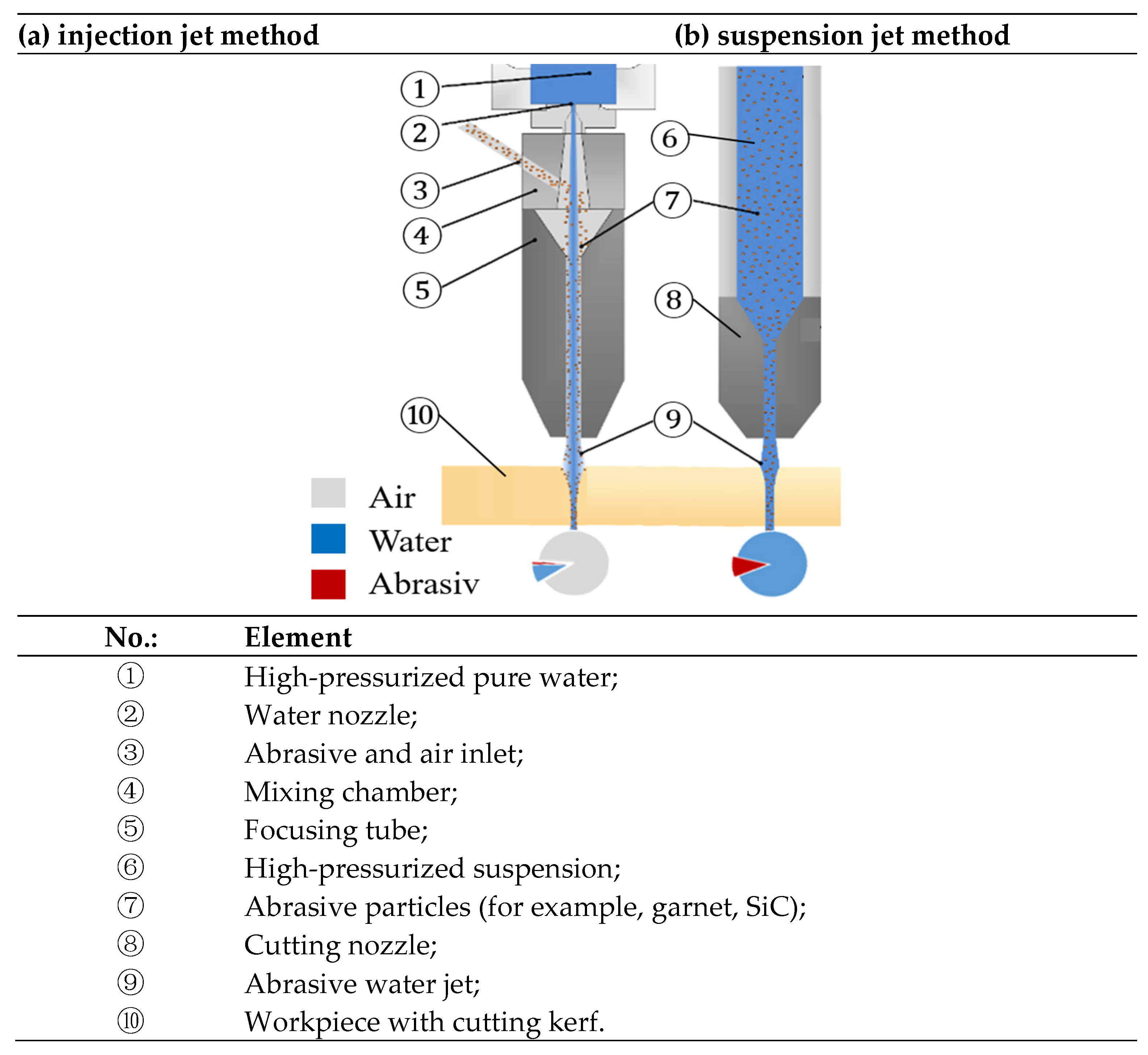
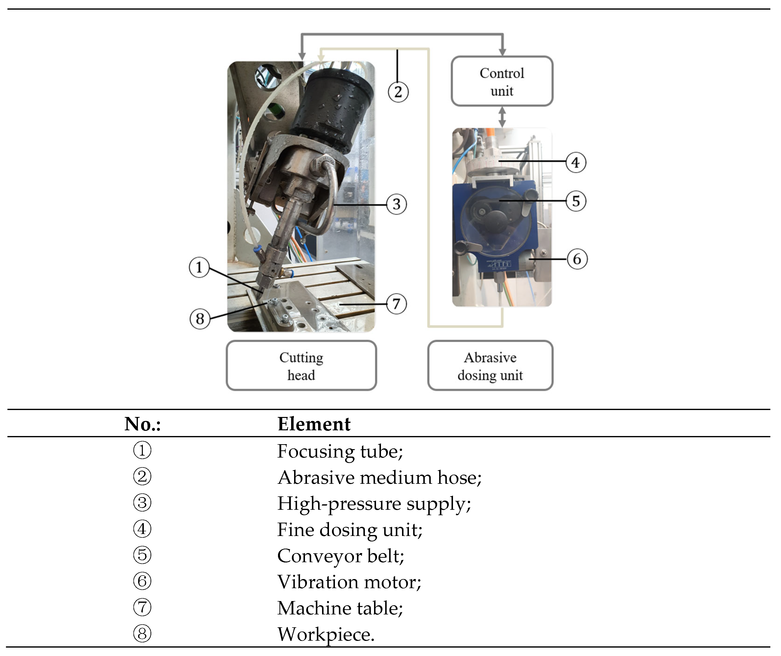
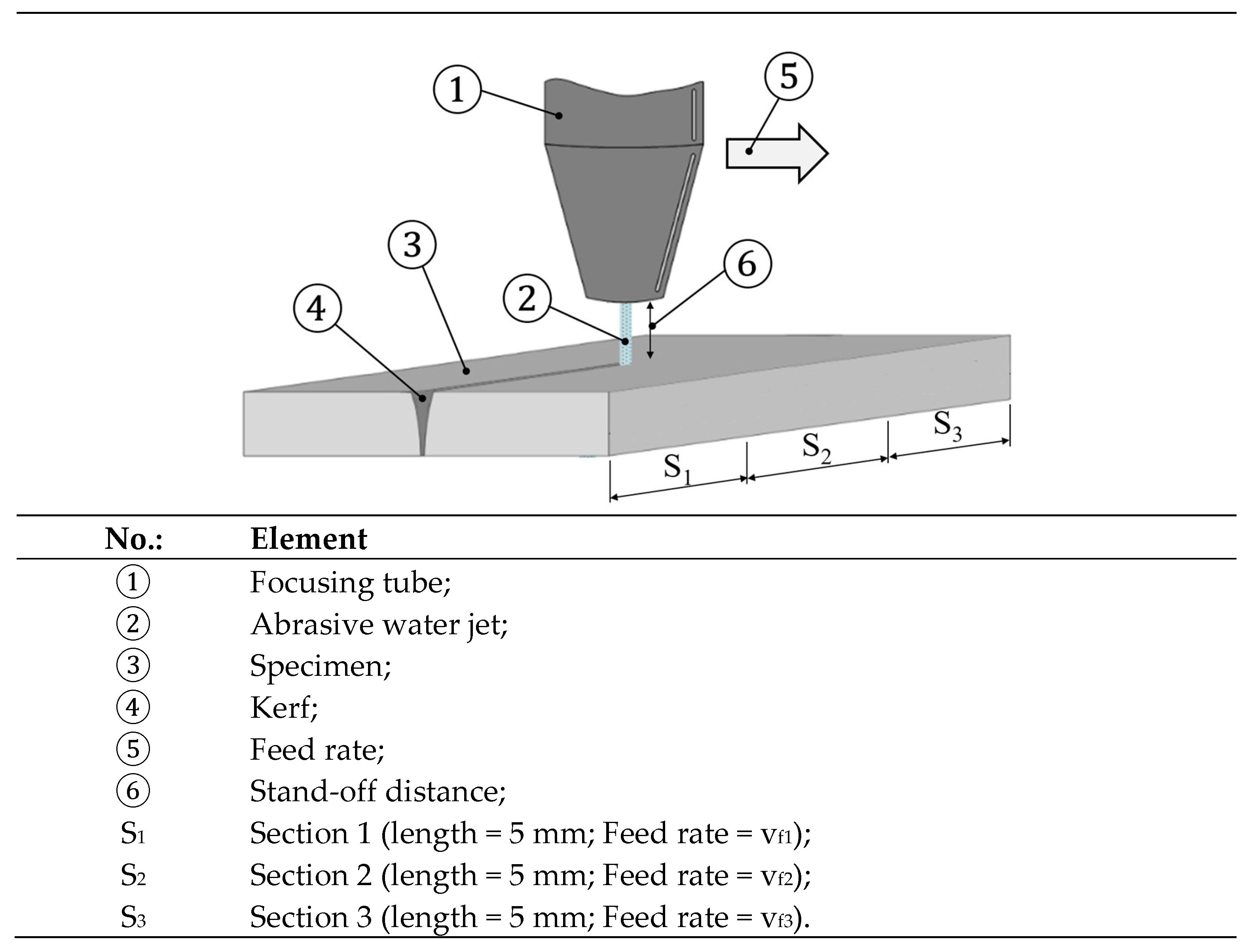
2.3. Abrasive Water Jet Cutting

In all abrasive water jet (AWJ) processes, a high-pressure water jet is used to accelerate added hard and sharp-edged abrasive particles. Garnet sand, corundum and SiC are primarily used for this purpose [68]. The particles impact the workpiece surface with high kinetic energy in a locally concentrated manner and remove material. The advantages of this process over other jet processes are the smallest jet diameters (<0.1 mm) [69] and low process forces [70], allowing thin-walled components to be manufactured with high material utilization. Another advantage is the high flexibility. This is demonstrated by the large number of manufacturing processes for which the abrasive water jet can be used in addition to cutting. For example, it can also be used for drilling, surface structuring, decoating, polishing, cleaning or for nonseparating processes, such as surface peening, which increases the relevance of the process for manufacturing in space. Further flexibility of the AWJ is demonstrated by the fact that a wide range of materials, for example, relevant for space applications (Section 1.4), can be machined. This includes soft materials, such as plastics [71], tough materials, such as metals [72], as well as thermal shock-sensitive and brittle materials, such as glasses [73] and technical ceramics [74]. In addition, composite materials, such as CFRP or sandwich materials, can also be processed [75]. However, according to the state of the art, two methods exist for generating an abrasive water jet. These two methods, the injection jet method and the suspension jet method, are shown in Figure 6.
In the first one, water is pressurized to 300–600 MPa and pressed through a nozzle, while accelerating to several 100 m/s. The jet formed entrains air corresponding to the Venturi effect and creates a negative pressure in the mixing chamber, drawing air into the mixing chamber through the abrasive feed. This gas flow is used to transport the abrasive into the mixing chamber. Furthermore, the three-phase jet is focused in the focusing tube. The suspension jet process, on the other hand, differs since a two-phase jet is formed. This is enabled by mixing the abrasive with the high-pressure water ahead of the nozzle, dispersing it and accelerating it together. Due to the absence of air in the jet, higher energy densities and higher particle loadings can be achieved in the water jet.

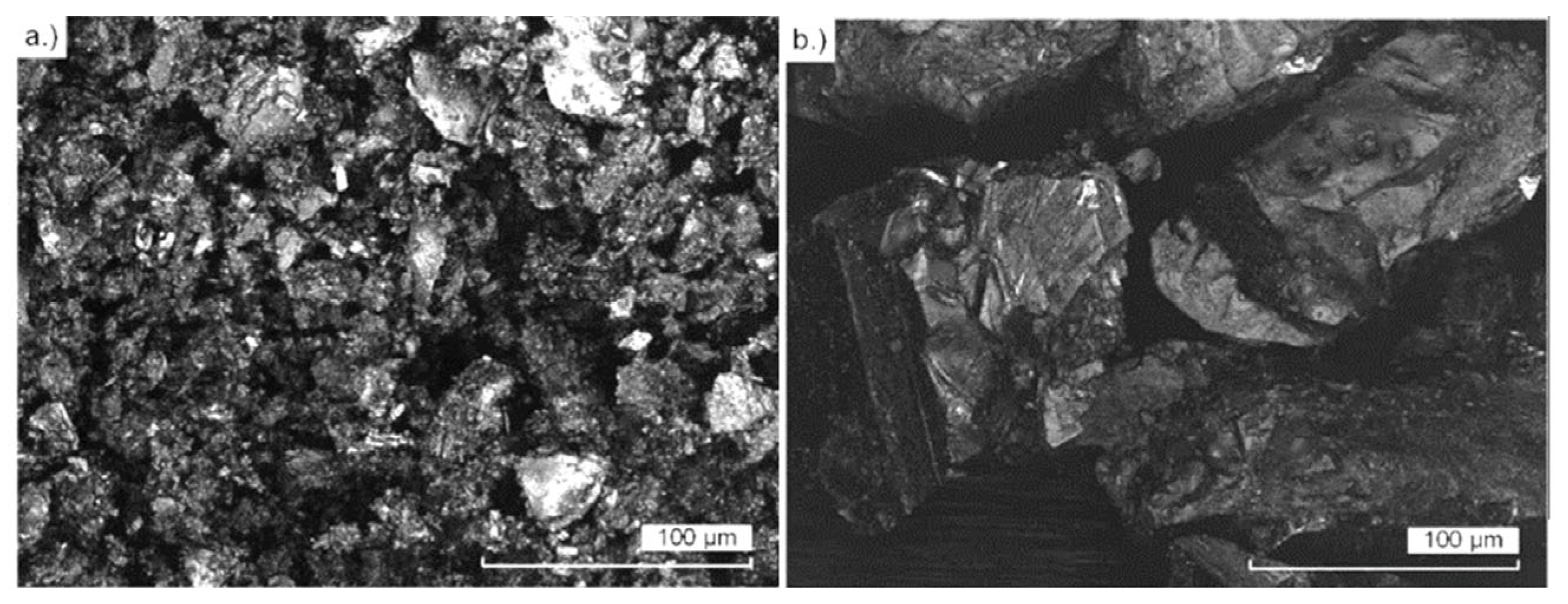
2.4. Regolith Simulate

Due to a lack of original material from the Moon, synthetic lunar soils, so-called regolith simulants, are used for earthly research. For the experiments described in this paper, two advanced regolith simulants, LX-T100 and LX-M100, from the TU Berlin were used. Each simulant consists of one of the dominant bedrocks of the Moon, basalt and anorthosite. In addition to the chemical and mineralogical composition, the simulants have the same particle shape and particle size distribution as the lunar regolith. LX-T100 is based on anorthosite rock. It consists predominantly of plagioclase (>95%). This material, thus, corresponds to the terrae material of the Moon in its pure form. LX-M100 is a simulant made of basalt, i.e., the material of the mare regions. It consists of 39% plagioclase, 42% pyroxene and 19% olivine. In terms of their particle morphology and particle size distribution, both simulants correspond to the average values of lunar regolith, which were determined from the samples from the Apollo and Luna missions. The chemical composition in the form of total oxides is shown in Table 10.

2.5. Aluminium Alloy

The key alloys used for the construction of current and future spacecraft are based on the main alloying element, aluminum (Section 1.4). The various types of aluminum may be divided into two general classes (a) casting alloys (those suitable for casting, for example, in regolith [76]) and (b) wrought alloys (those which may be shaped by rolling, drawing, or forging) and rather brought from planet earth (Section 1.4). However, a selection of aluminum alloys relevant to space applications [77] is shown in Table 11.
El-Hameed et al. [83] note that AA6061 is the most widely used 6xxx series alloy (Table 11) for spacecraft structures and satellite surfaces. One of the main characteristics of this alloy is its reduced sensitivity to solution heat treatment and quench variation compared to 7xxx and 2xxx series aluminum [84]. As a result, the nominal properties of the alloy can be achieved for greater material thicknesses, which, on the other hand, is beneficial to achieve greater moments of inertia, for example, to compensate for the comparatively low modulus of elasticity, which explains the use of the alloy class for structural components. Either way, it is plausible to assume that Al-Alloy 6061 is available for further use (Section 1.4). Moreover, according to Gradl [85], this alloy is also available for additive manufacturing (Section 1.6). Hence, Al-Alloy 6061 is selected as the representative metallic test material, while the chemical compositions of the samples are given in Table 12.
The selected test specimens have dimensions of 50 mm length, 90 mm width and 2.286 mm (0.09″) thickness with a specification according to Table 12. All the samples have an inspection certificate 3.1 according to DIN EN 10204 [87]. For the experimental investigations, a separating cut in the direction of the thickness was selected (cut thickness 2.286 mm, cut length 50 mm).

2.6. Lithium Silicate

A crystallizable lithium silicate glass (Table 13) was chosen as a feasibility material for developing glass and ceramic materials using in situ resources on the surface of the Moon.
Like most glass ceramic materials, a lithium silicate glass ceramic is produced in three steps:
  • Cast of the initial glass from a glass building melt;
  • Nucleation;
  • Crystal growth of the nuclei.
To build a glass ceramic with about 50% crystalline content, in the case of lithium silicate, first, lithium metasilicate crystallizes, which can be converted into lithium disilicate. For dental applications, this effect is used to yield, in the first step, glass ceramic with rather weak mechanical properties. Here, the glass ceramic can be easily machined to shape, for example, a dental crown. In the second step, by a short temperature process, the material is converted to a high-strength material. The crystallization processes for the lithium metasilicate and the lithium disilicate glass ceramics are listed in Table 14.
Therefore, the lithium silicate glass ceramic is predestinated as a feasibility material because it can be investigated in three stages:
  • Glass, representing other glasses;
  • Lithium monosilicate as the main crystal phase, representing rather weak ceramics;
  • Lithium disilicate as the main crystal phase, representing high-strength ceramics.
This is of special interest for lunar applications because it was shown that it is possible to manufacture a variety of basaltic glasses using lunar a regolith simulant and heating it within a susceptor-assisted microwave oven [88]. Either way, from these glasses, glass ceramics can also be built. Application scenarios for the use of glasses, on the other hand, are provided by Ulubeyli [89]. For the experimental investigations, a separating cut in the direction of the thickness was selected (cut thickness 7 mm, cut length 15 mm).

2.7. Experimental Procedure

The self-constructed five-axis fine jet test rig, partly shown in Figure 7, was used for the experimental investigation. A cutting head configuration with a water nozzle diameter of 0.1 mm and a focusing tube diameter of 0.3 mm was used (Figure 7, left). To convey the regolith simulate abrasive, a dosing unit (Allfi Group AG) adapted for lowest delivery rates was used (Figure 7, right). The latter can be adjusted via the speed control of the conveyor belt speed (Figure 7, right). Moreover, the flowability of the regolith simulate abrasive was supported using a vibration motor (Figure 7, right).
The basic prerequisite for a stable cutting process in abrasive water jet machining is a homogeneous abrasive flow. This requires a free-flowing abrasive since the smallest particles adhere to larger ones and consequently agglomerate with others (Figure 8a). To avoid agglomeration, small particles were removed from the abrasive by wet sieving (Figure 8b). The dried screenings were sieved and divided into fractions with particle sizes of 45–63 µm, 63–90 µm and 90–125 µm. These fractions were chosen because coarser particles can clog the focusing tube, whereas finer particles cannot be conveyed homogeneously.
Due to the lower density of the regolith simulant (2.90–3.25 g/cm3) [90], compared to conventional abrasives, such as garnet sand (4.12 g/cm3) [74], the common mass flow was reduced from a rate of 10 g/min [91] for garnet sand to 8.5 g/min for the regolith simulants. A test plan was set up for the aluminum material. For this purpose, the nozzle diameter dd, the stand-off distance s between the focusing tube outlet and the workpiece surface (Figure 9), the abrasive mass flow rate ṁp and the material thickness h are set as constant (Table 15).
Four parameters were selected for the feasibility study. The pressure p, converts the hydraulic power built up in the pump into the kinetic energy of the water and, thus, also of the abrasive particles. In preliminary tests, it was found that below a pressure of 200 MPa, no stable abrasive conveyance occurred due to powder agglomeration. The particle size fraction SF was chosen as the second factor. The three selected factor levels represent the particle sizes available on the Moon for potential lunar abrasive water jet processing. Furthermore, the particle size influences their mass and, thus, their material removal rate. The third factor is the chemical composition of the regolith material. The fourth factor is chosen to evaluate the performance of the process. For this purpose, the parameter of the related abrasive mass flow per 1 mm of machined workpiece surface ṁl is calculated from the ratio of feed rate vf and m’l. For the adjustment of ṁl, the abrasive mass flow was kept constant and vf was varied. All factors and factor levels are summarized in Table 16 with reference to Figure 9.
Moreover, Figure 9 schematically shows the execution and traversing strategy of the machining tests. After switching the water jet on, the abrasive supply is also switched on. Then, the lowest vf-level (Table 16) is applied in Section 1 of the workpiece (Figure 9). In Section 2, vf1 is increased to vf2 while m’l1 is reduced to m’l2. In Section 3, vf2 is increased to vf3 while m’l2 is reduced to m’l3.
After machining, the kerfs on the jet inlet and outlet side bt and bb (Figure 10) are measured using a Makrolite light microscope from the company Eurovision. However, the angular error u is calculated from the two kerf widths using Formula (1) to evaluate the parallelism of the cut.
u = b t b b 2 ,
If no complete cut through the material can be achieved, an evaluation of the angular error is not useful. For these cases, referred to as surface structuring, the erosion rate E is evaluated. The erosion rate indicates how much volume has been removed from the workpiece surface in relation to one gram of abrasive over a machined length of one millimeter. Furthermore, to assess the quality of the cut surfaces, the roughness Ra and Rz are measured in the lower 10% of the cut surface, as indicated in Figure 10. Nevertheless, a Keyence VK-9700 confocal microscope (KEYENCE, Osaka, Japan) with a scanning plane height of 2 μm was used to measure the kerfs and the cut surfaces. The variables to be measured and the positions of the variables to be evaluated are shown schematically in Figure 10.
Following the test plan with the aluminum material (Table 16), individual cutting tests were carried out with the lithium silicate materials in the various states analogous to the tests described for the aluminum material. However, the parameter combinations used for the individual tests are summarized in Table 17.

3. Results

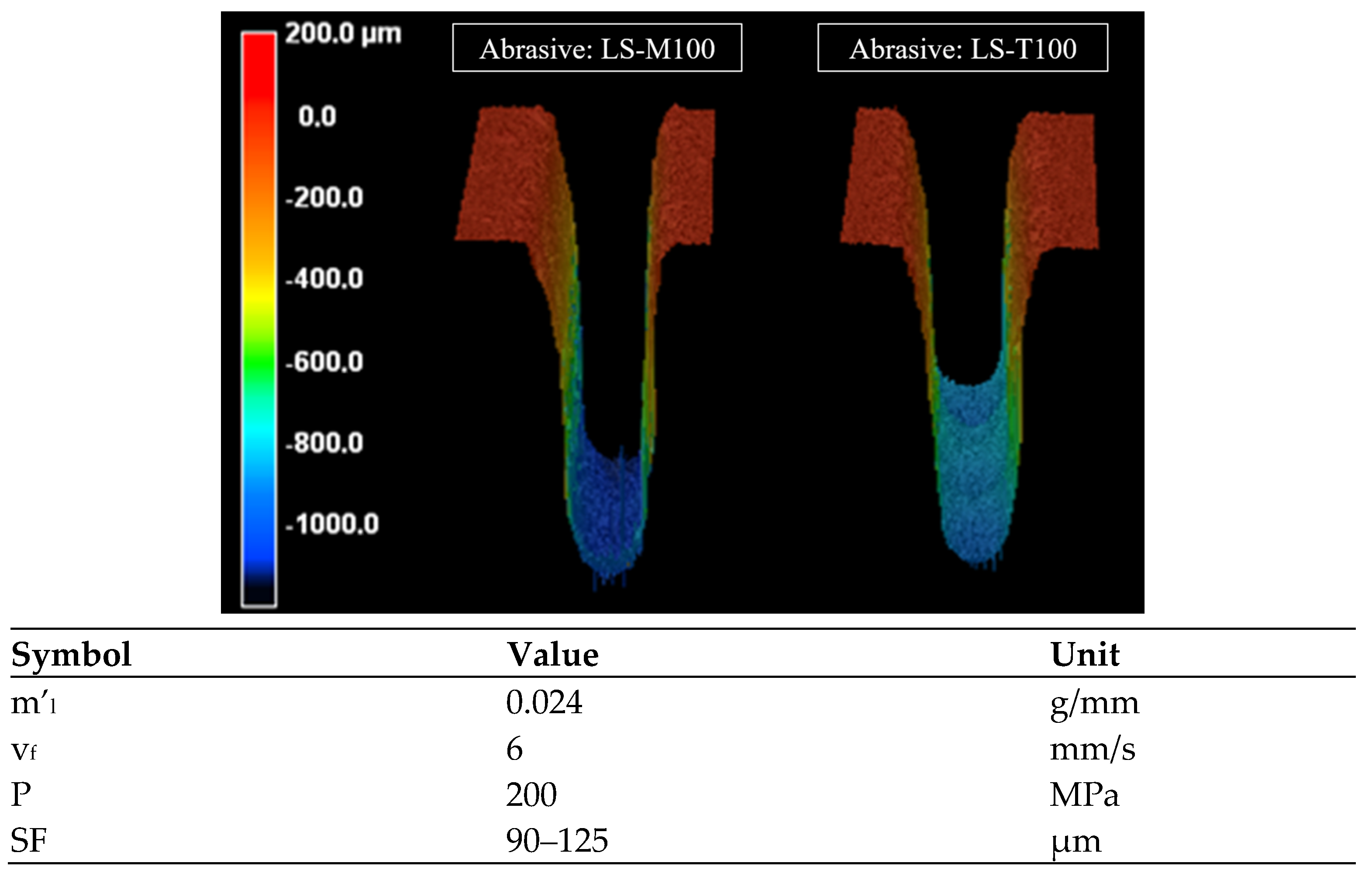
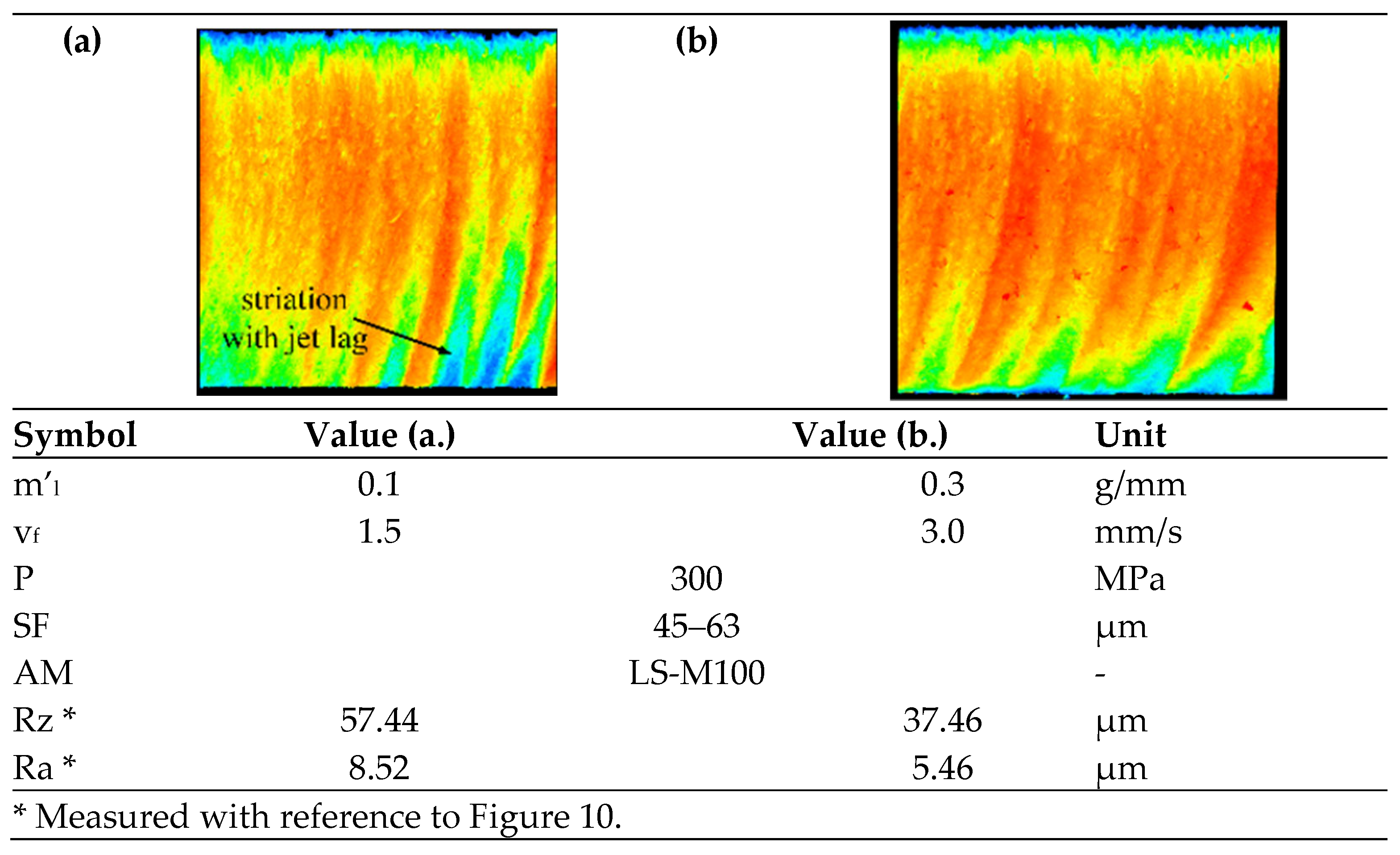
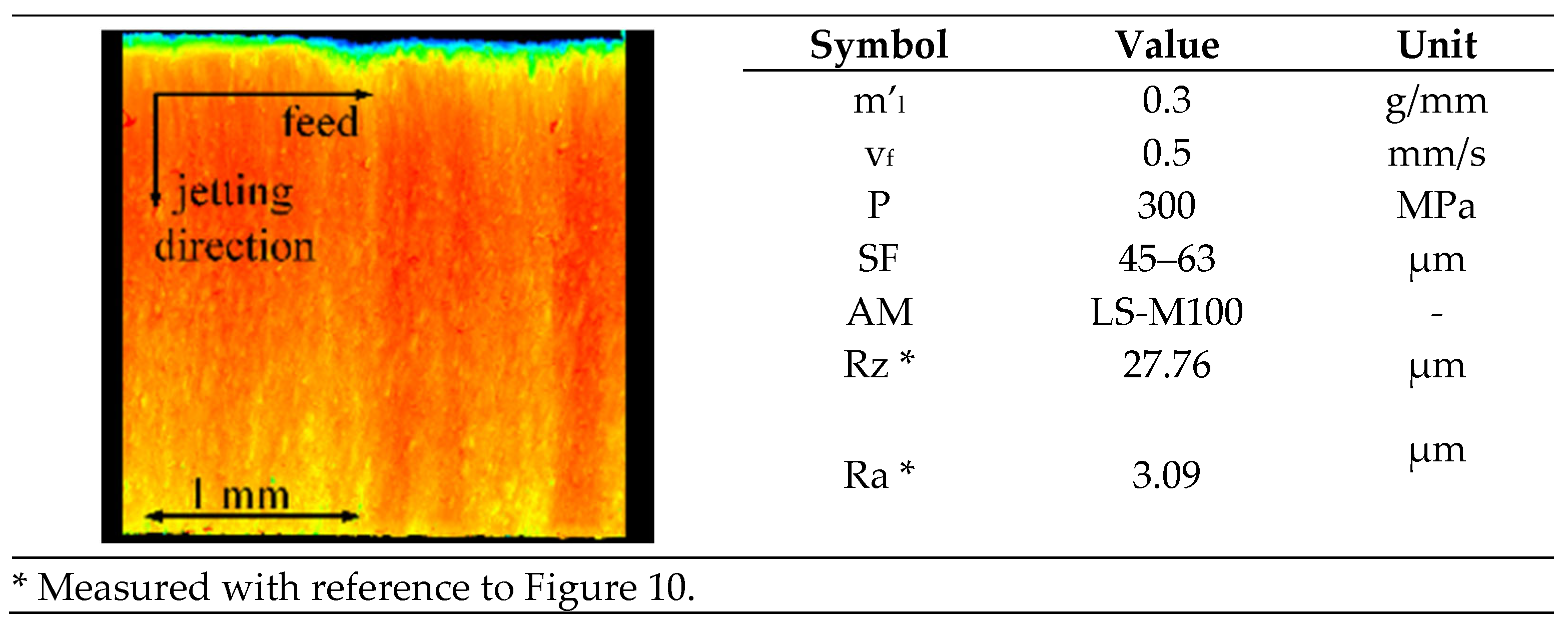
3.1. Water Jet Machining of Al-Alloy

The aluminum material could be processed with regolith simulants. The identified process limits are shown in Figure 11. This diagram shows a classification of the process stability during AWJ of the aluminum alloy 6061 T6 as a function of the feed rate vf, the pump pressure p and the particle size distribution for the regolith substrates LS-M100 and LS-T100 and the limits for the varied factors indicating where the workpiece could no longer be cut completely. The result, however, is a transition towards surface removal in terms of surface structuring, as explained in Section 2.7.
As is common for AWJ machining, the kerfs showed tapering gaps (Figure 10). The kerf width on the jet entry side was independent of all factors (Table 17) in the range of 0.3–0.4 mm (Figure 12).
On the other hand, as shown in Figure 13, all investigated factors show an effect on the angular error u. As expected, u is reduced with increasing pressure. In fact, this is explained by the higher kinetic energy due to the increased particle velocity since higher energy input increases the erosion rate. The energy input, again, increases as the feed rate is reduced or ṁl is increased. Hence, a high ṁl also leads to a reduction of the angular error. Furthermore, an influence of the particle size on the angular error could be observed. This is explained by the higher mass and the resulting increase in the kinetic energy of the particles. However, the influence of the particle size change on the angular error turns out to be small.
A higher material removal rate, in turn, can be achieved by varying the particle size at shallower impact angles, as is the case with surface erosion where a full-cut kerf has not yet been formed. This can be deduced from the increase in erosion rate due to the increase in particle size at the lowest m’l. Furthermore, differences were found due to the variation of the abrasive material used. During the tests, it could be observed that the conveyability of LS-M100 is better than LS-T100. Moreover, the erosion rates of the LS-M100 material were higher than those of LS-T100 and the angular errors were lower. Although LS-T100 has a significantly higher amount of Al2O3 as a hard abrasive than LS-M100, the higher erosion rates can be attributed to the much better conveyability of LS-M100.
As a result, it was possible to machine the samples with higher feed rates and, thus, higher productivity. As an example, two notches where only the abrasive material was the varied parameter are shown in Figure 14. Either way, determining the cause of this difference requires further investigation, while the chemical composition is expected to be the cause (Table 12). Regarding the roughness (Figure 10), in turn, no effect could be observed for the pressure factor. In fact, minimum roughness’s of Ra 2 µm and Rz 25 µm could be achieved by increasing m’l.
However, Figure 15 shows different confocal microscope images of samples where only m’l was varied. In these images, it can be observed how typical grooves of the water abrasive jet process develop on the jet exit side with decreasing m’l. It can also be seen that the deflection of the water jet increases with increasing feed rate or increasing mass flow per 1 mm of machined workpiece. The jet, therefore, lags, as the cutting pressure to cut the material remains almost constant (Figure 15).
Either way, this characteristic can be avoided by suitably adjusting the process parameters (Figure 16).

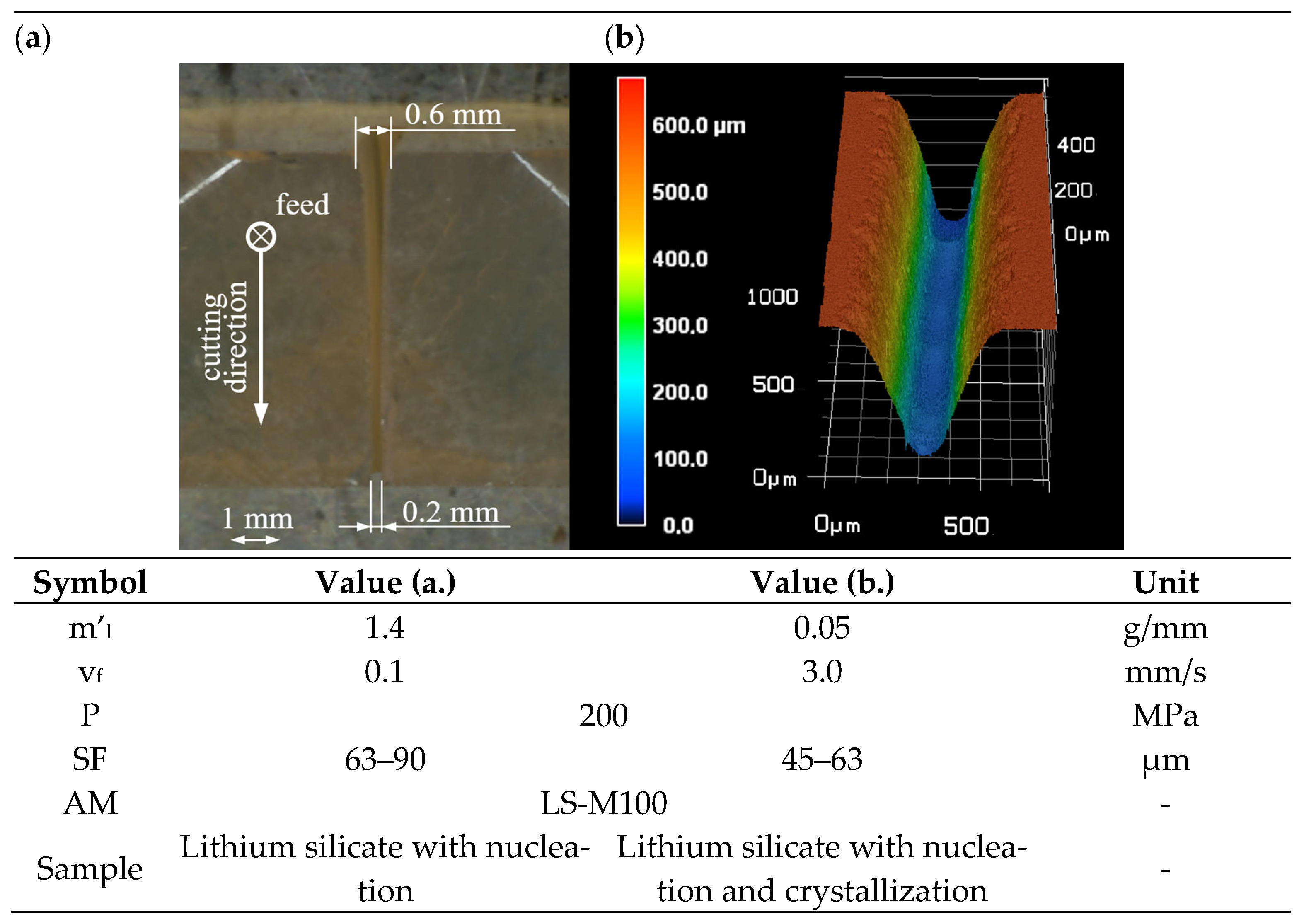
3.2. Water Jet Machining of Lithium Silicate

First, parameter adjustments were necessary for the lithium silicate samples because of the deviations compared to the aluminum samples (Section 2.5 and Section 2.6). In fact, the lithium silicate samples have a greater thickness, and the material has higher hardness. Either way, all three states of lithium silicate are suitable for both cutting and surface removal with the abrasive water jet process using regolith simulate as the abrasive. Only the lithium silicate in nucleation and crystallization conditions (representing high-strength ceramics) could inertially be processed to a limited extent, as samples broke in the clamping during processing, despite the low process forces. Moreover, the materials tended to crack at pressures of 300 MPa (Table 17), resulting in a water pressure reduction to 200 MPa. The qualitative evaluation (Figure 17) shows a larger kerf width on the jet entry side (0.5–0.6 mm) of the aluminum material. Furthermore, a larger taper is visible, which is in line with the state of the art for water jet machining of hard materials. Either way, the notched sample in Figure 17 shows a uniform cutting depth.

4. Discussion and Conclusions

This paper addresses an innovative approach to subtractive processing based on in situ resource utilization. Based on a review of the available resources on the Moon, a comprehensive literature search on the state of the art in in-space manufacturing processes was presented. Moreover, a research gap in the field of subtractive processing was identified. On this basis, water jet cutting was selected as a versatile cutting technique and explored for its applicability on the Moon. The main purpose of the investigations was a proof of concept with a focus on the use of local resources and space-representative materials. In summary, it is concluded that no contradictions were identified about the line of argument that led to the selected method using the selected system technology and materials, although further research is needed. From a technical point of view, it is concluded that:
  • It is possible to perform an abrasive water jet cutting and removal process with regolith simulant on the tested materials;
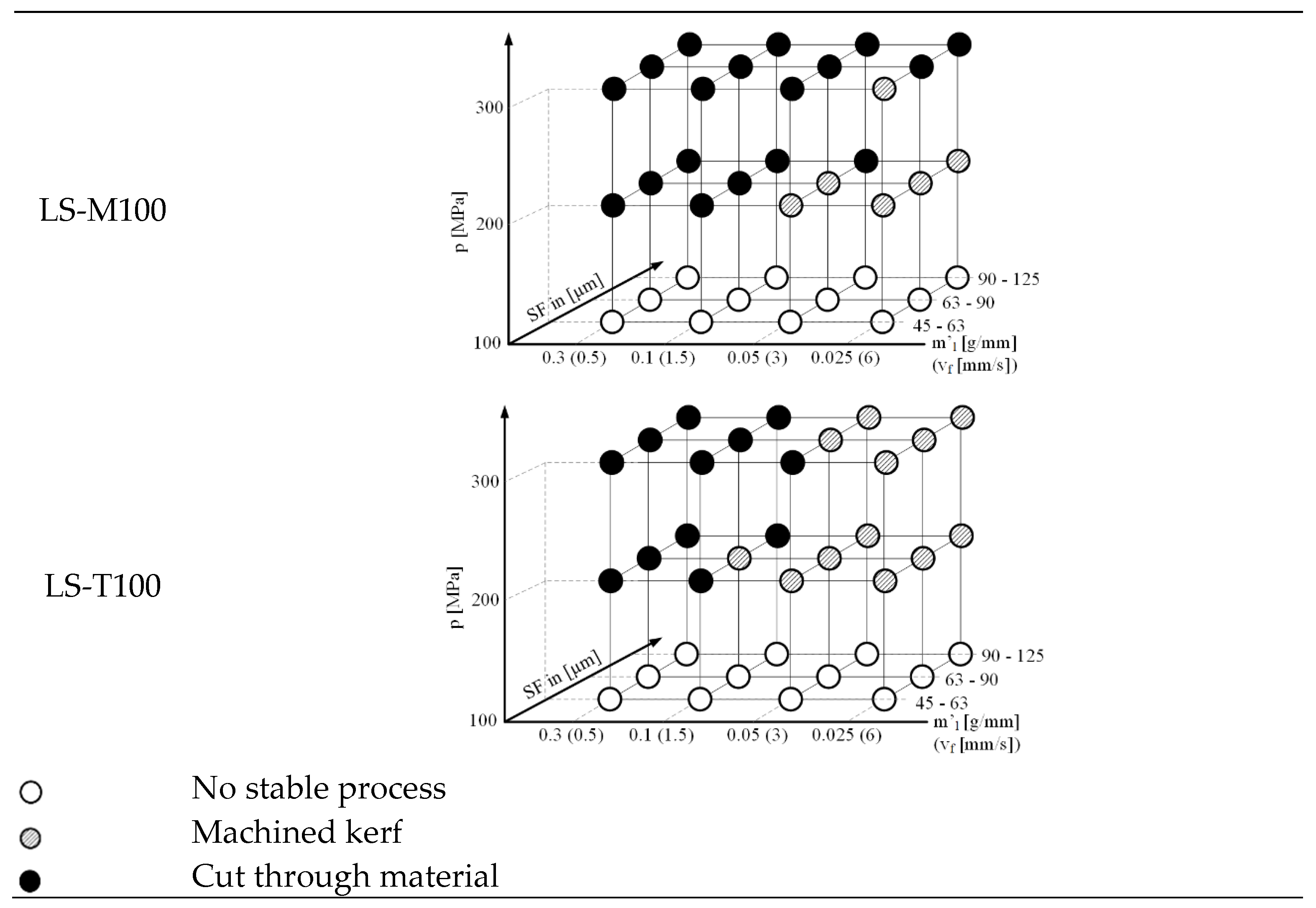
  • LS-M100, the sieved regolith simulant made of basalt representing the material of the mare regions, has a higher suitability as an abrasive due to the higher erosion rates that could be achieved;
  • In order to enable the regolith simulant to be conveyed, the abrasive must be sieved, and small particle adhesions must be removed;
  • For the regolith particle fractions of 45–63 μm, 63–90 μm and 90–125 μm, the experimentally determined water jet pressure for stable particle transport was between 200 and 300 MPa;
  • It is possible to cut and kerf the aluminum material in the investigated test field, whereby the generated geometries are similar to the geometries generated by means of common abrasives with regard to their topography;
  • It is possible to machine the investigated lithium materials with the selected test parameters. As with the Al material, typical cutting and kerf geometries are produced for the abrasive water jet technology;
  • Uniformly deep kerf can be created with the regolith simulant;
  • In the case of lithium silicate materials, due to the brittleness of the materials, the machining strategy must be adapted, for example, via pressure ramps, in order to prevent breakouts.

5. Outlook

The following aspects will be considered as part of the continuation of the present research work:
  • Comprehensive quantification of the results;
  • Comparison of test results;
  • Analysis of the cut surfaces;
  • Determination of erosion rates in surface structuring;
  • Check the reusability of abrasives;
  • Scale/scalability of hardware in terms of power (maximum power for ISS payload is 2 kw), mass and volume, safety (chip debris capture), limited crew interaction, remote commanding, etc.;
  • Operation in reduced gravity (physics of removal);
  • Application/operation in an encapsulated environment with circulation of the utilized materials.

Author Contributions

A.S.: conceptualization (equal); data curation (equal); investigation (equal); methodology (equal); validation (equal); visualization (equal); writing—original draft (lead); supervision (equal); U.T.: formal analysis (equal); investigation (equal); visualization (equal); writing—original draft (equal). S.I.: funding acquisition (equal); supervision (equal); writing—review and editing (equal); resources (equal); K.S.: conceptualization (equal); formal analysis (equal); investigation (equal); methodology (equal); F.M.: investigation (equal); data curation (equal); writing—review and editing (equal). M.D.: funding acquisition (equal); supervision (equal); writing—review and editing (equal): resources (equal); R.N.: data curation (equal); investigation (equal); methodology (equal); writing—review and editing (equal). B.D.: data curation (equal); investigation (equal); methodology (equal); writing—review and editing (equal). S.L.: conceptualization (equal); formal analysis (equal); investigation (equal); visualization (equal); writing—original draft (equal); funding acquisition (equal); supervision (equal); resources (equal). All authors have read and agreed to the published version of the manuscript.

Funding

The authors thank their institutions named: Fraunhofer Institute for Machine Tools and Forming Technology IWU, TU Chemnitz, Fraunhofer Institute for Silicate Research ISC and TU Berlin for internal funding. The study was also co-financed by the CPS project from taxes on the basis of the budget passed by the Saxon state parliament.

Institutional Review Board Statement

Not applicable.

Informed Consent Statement

Not applicable.

Data Availability Statement

The data that support the findings of this study are available from the corresponding author, [email protected], upon reasonable request. The data are not publicly available due to privacy.

Conflicts of Interest

The authors declare no conflict of interest.

References

  1. Prater, T.; Werkheiser, M.J.; Ledbetter, F.; Morgan, K. In-Space Manufacturing at NASA Marshall Space Flight Center: A Portfolio of Fabrication and Recycling Technology Development for the International Space Station. In Proceedings of the 2018 AIAA SPACE and Astronautics Forum and Exposition, Orlando, FL, USA, 17–19 September 2018. [Google Scholar]
  2. Norman, A.; Das, S.; Rohr, T.; Ghidini, T. Advanced manufacturing for space applications. CEAS Space J. 2022, 15, 1–6. [Google Scholar] [CrossRef]
  3. Owens, A.; de Weck, O. Systems Analysis of In-Space Manufacturing Applications for the International Space Station and the Evolvable Mars Campaign. In Proceedings of the AIAA SPACE 2016, Long Beach, CA, USA, 13–16 September 2016. [Google Scholar]
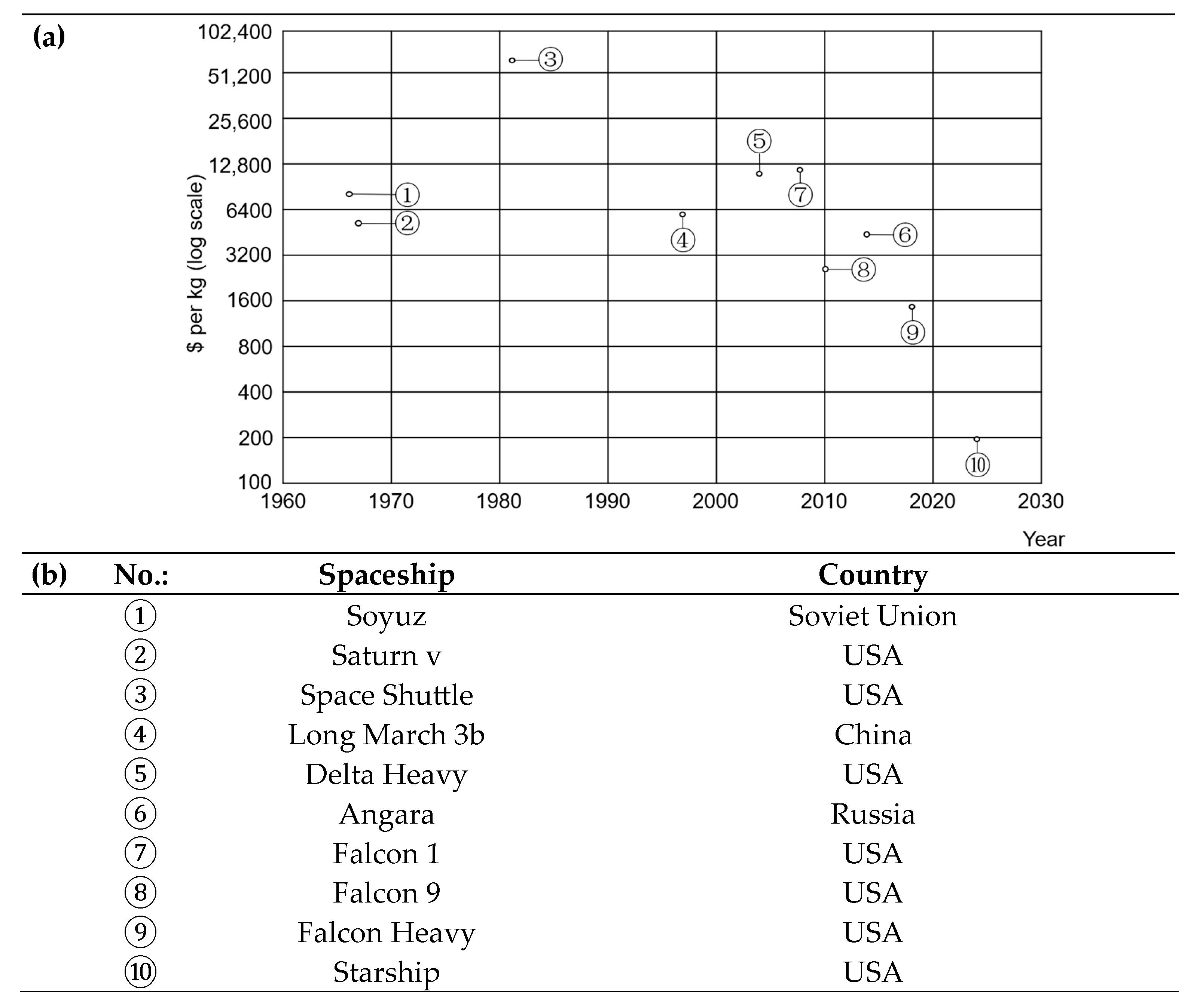
  4. Venditti, B.; Parker, S. The Cost of Space Flight before and after SpaceX. Available online: https://www.visualcapitalist.com/the-cost-of-space-flight/ (accessed on 15 December 2023).
  5. Arianespace Service & Aolutions, Soyuz User’s Manual Issue 2 Revision 0. Available online: https://www.arianespace.com/wp-content/uploads/2015/09/Soyuz-Users-Manual-March-2012.pdf (accessed on 25 April 2023).
  6. National Aeronautics and Space Administration (NASA). SATURN V FLIGHT MANUAL: SA 507. Available online: https://history.nasa.gov/afj/ap12fj/pdf/a12_sa507-flightmanual.pdf (accessed on 25 April 2023).
  7. Gatland, K.; Hewish, M.; Wright, P. The Space Shuttle Handbook; The Hamlyn Publishing Group Ltd.: London, UK, 1979. [Google Scholar]
  8. China Academy of Launch Vehicle Technology. LM-3B USER’S MANUAL. Available online: https://www.mach5lowdown.com/wp-content/uploads/PUG/LM-3B-User-Manual-v1999.pdf (accessed on 25 April 2023).
  9. United Launch Alliance. DELTA IV HEAVY. Available online: https://www.ulalaunch.com/docs/default-source/rockets/delta-iv-heavy-cutaway.pdf (accessed on 25 April 2023).
  10. International Launch Services. Angara 1.2 FLIGHT-PROVEN LAUNCH VEHICLE. Available online: https://www.ilslaunch.com/launch-vehicle/angara-1-2/ (accessed on 25 April 2023).
  11. SpaceX, FALCON USER’S GUIDE. Available online: https://www.spacex.com/media/falcon-users-guide-2021-09.pdf (accessed on 25 April 2023).
  12. SpaceX, STARSHIP USERS GUIDE: REVISION 1.0 March 2020. Available online: https://www.spacex.com/media/starship_users_guide_v1.pdf (accessed on 25 April 2023).
  13. Makaya, A.; Pambaguian, L.; Ghidini, T.; Rohr, T.; Lafont, U.; Meurisse, A. Towards out of earth manufacturing: Overview of the ESA materials and processes activities on manufacturing in space. CEAS Space J. 2022, 15, 69–75. [Google Scholar] [CrossRef]
  14. Del Bianco, M.; Lanciano, O.; Bertacin, R.; Piccirillo, S.; Paillet, A.; Boutte, P.; Tan, E.; Picard, M.; Floyd, M.; On, M.; et al. IN-SITU RESOURCE UTILIZATION GAP ASSESSMENT REPORT. 2021. Available online: https://www.globalspaceexploration.org/wordpress/wp-content/uploads/2021/04/ISECG-ISRU-Technology-Gap-Assessment-Report-Apr-2021.pdf (accessed on 15 December 2023).
  15. Anand, M.; Crawford, I.A.; Balat-Pichelin, M.; Abanades, S.; Van Westrenen, W.; Péraudeau, G.; Jaumann, R.; Seboldt, W. A brief review of chemical and mineralogical resources on the Moon and likely initial in situ resource utilization (ISRU) applications. Planet. Space Sci. 2012, 74, 42–48. [Google Scholar] [CrossRef]
  16. Sanders, G. ISRU: An Overview of NASA’s Current Development Activities and Long-Term Goals; NASA: Reno, NV, USA, 2000.
  17. Nakamura, T.; Smith, B. Solar Thermal Power System for Lunar ISRU Applications: Result of ISRU Analog Test, Mauna Kea, HI. In Proceedings of the AIAA SPACE 2010 Conference & Exposition, Anaheim, CA, USA, 30 August–2 September 2010. [Google Scholar]
  18. Sanders, G.; Larson, W.; Sacksteder, K.; Mclemore, C. NASA In-Situ Resource Utilization (ISRU) Project: Development and Implementation. In Proceedings of the AIAA SPACE 2008 Conference & Exposition, San Diego, CA, USA, 9–11 September 2008. [Google Scholar]
  19. Anih, S. Crewed Space Mission Waste-Streams and Impact on Human Exploration of Mars. In Assessing a Mars Agreement Including Human Settlements; Froehlich, A., Ed.; Springer International Publishing: Cham, Switzerland, 2021; pp. 129–146. [Google Scholar]
  20. Belvin, W.K.; Doggett, W.R.; Watson, J.J.; Dorsey, J.T.; Warren, J.E.; Jones, T.C.; Komendera, E.E.; Mann, T.; Bowman, L.M. In-Space Structural Assembly: Applications and Technology. In Proceedings of the 3rd AIAA Spacecraft Structures Conference, San Diego, CA, USA, 4–8 January 2016. [Google Scholar] [CrossRef]
  21. Spedding, C.P.; Lim, S.; Nuttall, W.J. ISRU technology deployment at a lunar outpost in 2040: A Delphi survey. Acta Astronaut. 2021, 181, 316–324. [Google Scholar] [CrossRef]
  22. Sanders, G.; Kleinheinz, J.; Linne, D. NASA Plans for In Situ Resource Utilization (ISRU) Development, Demonstration, and Implementation; NASA: Reno, NV, USA, 2022.
  23. Bart, G.D.; Nickerson, R.D.; Lawder, M.T.; Melosh, H. Global survey of lunar regolith depths from LROC images. Icarus 2011, 215, 485–490. [Google Scholar] [CrossRef]
  24. Linke, S.; Voß, A.; Ernst, M.; Taschner, P.A.; Baasch, J.; Stapperfend, S.; Gerdes, N.; Koch, J.; Weßels, P.; Neumann, J.; et al. Two-Dimensional Laser Melting of Lunar Regolith Simulant Using the MOONRISE Payload on a Mobile Manipulator. 3D Print. Addit. Manuf. 2022, 9, 223–231. [Google Scholar] [CrossRef] [PubMed]
  25. Kalapodis, N.; Kampas, G.; Ktenidou, O.-J. A review towards the design of extraterrestrial structures: From regolith to human outposts. Acta Astronaut. 2020, 175, 540–569. [Google Scholar] [CrossRef]
  26. Cesaretti, G.; Dini, E.; De Kestelier, X.; Colla, V.; Pambaguian, L. Building components for an outpost on the Lunar soil by means of a novel 3D printing technology. Acta Astronaut. 2014, 93, 430–450. [Google Scholar] [CrossRef]
  27. Sommariva, A.; Gori, L.; Chizzolini, B.; Pianorsi, M. The economics of moon mining. Acta Astronaut. 2020, 170, 712–718. [Google Scholar] [CrossRef]
  28. Jolly, S.D.; Happel, J.; Sture, S. Design and Construction of Shielded Lunar Outpost. J. Aerosp. Eng. 1994, 7, 417–434. [Google Scholar] [CrossRef]
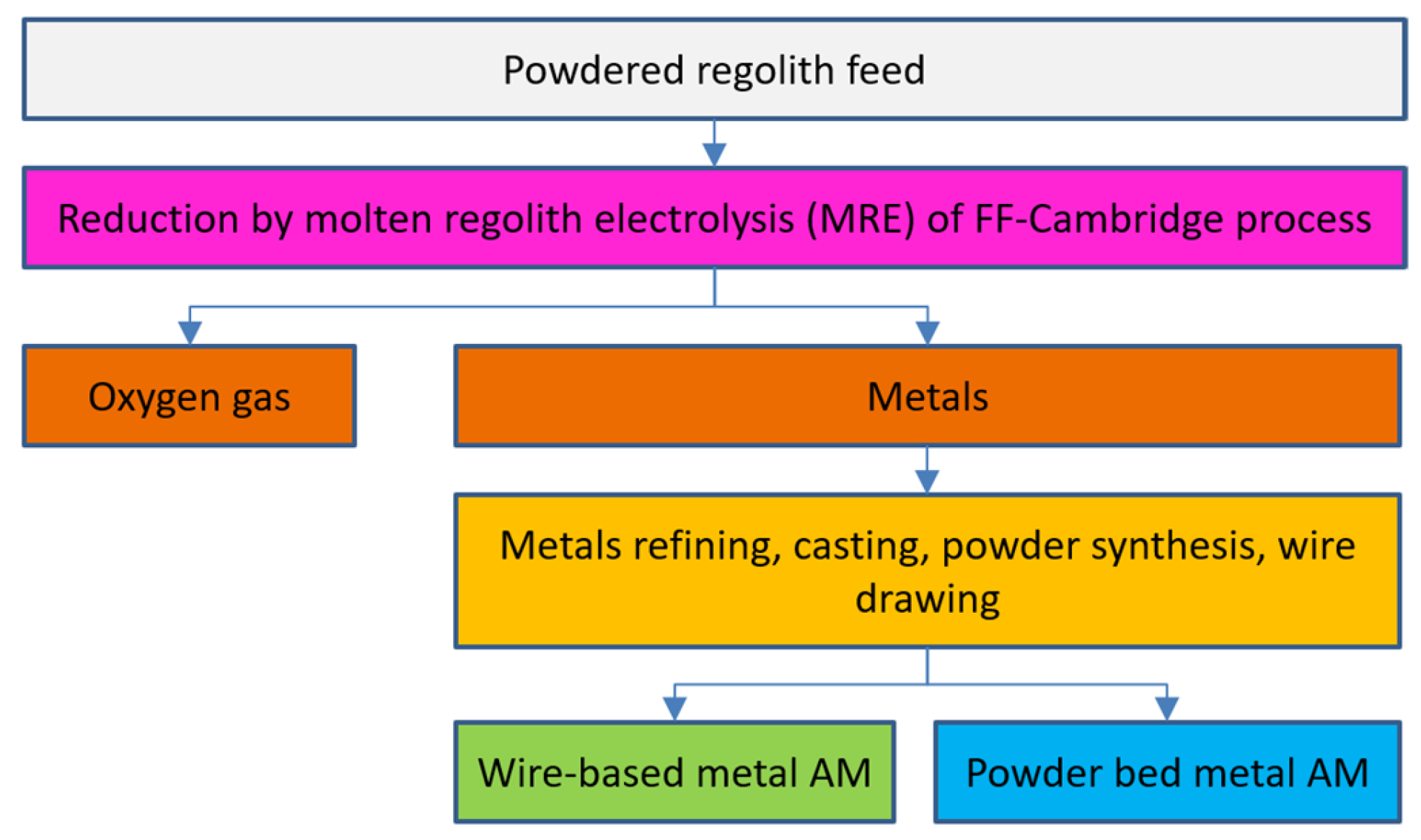
  29. Lomax, B.A.; Conti, M.; Khan, N.; Bennett, N.S.; Ganin, A.Y.; Symes, M.D. Proving the viability of an electrochemical process for the simultaneous extraction of oxygen and production of metal alloys from lunar regolith. Planet. Space Sci. 2020, 180, 104748. [Google Scholar] [CrossRef]
  30. Jolliff, B.L.; Wieczorek, M.A.; Shearer, C.K.; Neal, C.R. New Views of the Moon; De Gruyter: Berlin, Germany, 2006. [Google Scholar]
  31. Collinson, D.W. Lunar sourcebook—A user’s guide to the moon. Phys. Earth Planet. Inter. 1992, 72, 132–133. [Google Scholar] [CrossRef]
  32. Taylor, S.R.; Norman, M.D.; Esat, T. The Lunar Highland Crust: The Origin of the MG Suite. Meteorit. Planet. Sci. 1993, 28, 448. [Google Scholar]
  33. Sebastian, U. Gesteinskunde: Ein Leitfaden für Einsteiger und Anwender, 3., Überarb. und Aktualisierte Aufl.; Springer Spektrum: Berlin/Heidelberg, Germany, 2014. [Google Scholar]
  34. Taylor, S.R. Lunar Science: Scientific Results and Insights from the Lunar Samples; Elsevier Science: Kent, UK, 2016. [Google Scholar]
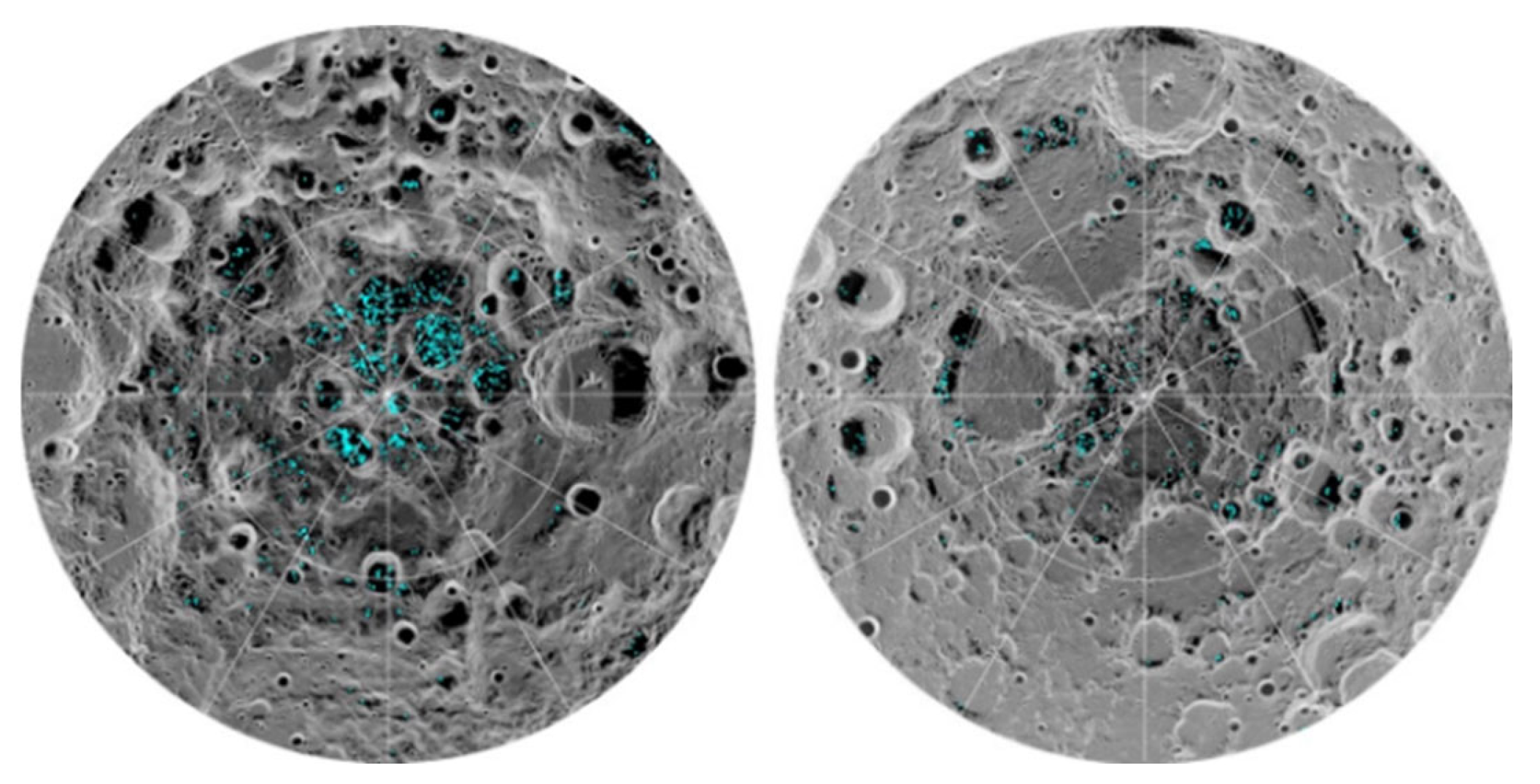
  35. Casanova, S.; Espejel, C.; Dempster, A.G.; Anderson, R.C.; Caprarelli, G.; Saydam, S. Lunar polar water resource exploration—Examination of the lunar cold trap reservoir system model and introduction of play-based exploration (PBE) techniques. Planet. Space Sci. 2019, 180, 104742. [Google Scholar] [CrossRef]
  36. Culler, J. Ice Confirmed at the Moon’s Poles. Available online: https://www.jpl.nasa.gov/news/ice-confirmed-at-the-moons-poles (accessed on 11 May 2023).
  37. Kornuta, D.; Abbud-Madrid, A.; Atkinson, J.; Barr, J.; Barnhard, G.; Bienhoff, D.; Blair, B.; Clark, V.; Cyrus, J.; DeWitt, B.; et al. Commercial lunar propellant architecture: A collaborative study of lunar propellant production. REACH 2019, 13, 100026. [Google Scholar] [CrossRef]
  38. Robert, P.M. (Ed.) Lunar Base Construction Planning, Earth and Space; NASA: Reno, NV, USA, 2022.
  39. Sgambati, A.; Berg, M.; Makaya, A. lUnaR Base Additive maNufacturing (URBAN) Executive Summary Report. 2018. Available online: https://nebula.esa.int/sites/default/files/neb_study/2507/C4000122380ExS.pdf (accessed on 15 December 2023).
  40. Stenzel, C.; Weiss, L.; Rohr, T. Sustainable challenges on the moon. Curr. Opin. Green Sustain. Chem. 2018, 9, 8–12. [Google Scholar] [CrossRef]
  41. Uzo-Okoro, E. IN-SPACE SERVICING, ASSEMBLY, AND MANUFACTURING NATIONAL STRATEGY: Product of the IN-SPACE SERVICING, ASSEMBLY, AND MANUFACTURING INTERAGENCY WORKING GROUP of the NATIONAL SCIENCE & TECHNOLOGY COUNCIL. 2022. Available online: https://www.whitehouse.gov/wp-content/uploads/2022/04/04-2022-ISAM-National-Strategy-Final.pdf (accessed on 15 December 2023).
  42. Willcoxon, R.; Thronson, H.; Varsi, G.; Mueller, R.; Regenie, V.; Inman, T.; Crooke, J.; Coulter, D. NASA Capability Roadmaps Executive Summary; NTRS-NASA Technical Reports Server (Internet): Reno, NV, USA, 2013. [Google Scholar]
  43. Karl, D.; Cannon, K.M.; Gurlo, A. Review of space resources processing for Mars missions: Martian simulants, regolith bonding concepts and additive manufacturing. Open Ceram. 2022, 9, 100216. [Google Scholar] [CrossRef]
  44. National Aeronautics and Space Administration (NASA). Space Tools On Demand: 3D Printing in Zero G: NASA Facts. Available online: https://www.nasa.gov/sites/default/files/atoms/files/fs_3dprinting_factsheet_140502.pdf (accessed on 21 April 2023).
  45. Kramer, H.J. ISS: AMF (Additive Manufacturing Facility). Available online: https://www.eoportal.org/other-space-activities/iss-amf#an-overview-of-ism-in-space-manufacturing (accessed on 25 April 2023).
  46. Werkheiser, N. The In-Space Refabricator. Available online: https://science.nasa.gov/science-news/news-articles/the-in-space-refabricator (accessed on 25 April 2023).
  47. European Space Agency. In-Orbit Manufacturing of Very Long Booms. Available online: https://www.esa.int/Enabling_Support/Space_Engineering_Technology/Shaping_the_Future/In-Orbit_Manufacturing_of_Very_Long_Booms (accessed on 25 April 2023).
  48. Kringer, M.; Schaefer, N.T.; Boehrer, C.; Frey, M.; Schill, F.; Kullmann, M.; Strasser, M.; Pietras, M. Meet the Teams: AIMIS-FYT. Available online: https://www.esa.int/Education/Fly_Your_Thesis/Meet_the_teams_AIMIS-FYT (accessed on 25 April 2023).
  49. European Space Agency. IMPERIAL: 3D Printing’s New Dimension. Available online: https://www.esa.int/ESA_Multimedia/Videos/2022/03/IMPERIAL_3D_printing_s_new_dimension (accessed on 25 April 2023).
  50. European Space Agency. Portable On-Board Printer (POP3D Printer). Available online: https://www.esa.int/ESA_Multimedia/Images/2014/11/POP3D_printer (accessed on 25 April 2023).
  51. European Space Agency. MELT 3D Printer. Available online: https://www.esa.int/ESA_Multimedia/Images/2018/10/MELT_3D_printer (accessed on 25 April 2023).
  52. Sher, D. China Operates Continuous Composites 3D Printer in Space: The Autonomous System Was Launched with the New Long March 5B Rocket. Available online: https://www.voxelmatters.com/china-operates-autonomous-continuous-composites-3d-printer-in-space/ (accessed on 25 April 2023).
  53. Zocca, A.; Lüchtenborg, J.; Mühler, T.; Wilbig, J.; Mohr, G.; Villatte, T.; Léonard, F.; Nolze, G.; Sparenberg, M.; Melcher, J.; et al. Enabling the 3D Printing of Metal Components in µ-Gravity. Adv. Mater. Technol. 2019, 4, 1900506. [Google Scholar] [CrossRef]
  54. Airbus, D.S. In Space Manufacturing and Assembly: Delivering Technological Bricks for Airbus Space Factory. Available online: https://www.airbus.com/en/newsroom/news/2022-05-in-space-manufacturing-and-assembly (accessed on 25 April 2023).
  55. Peels, J. Space Metal 3D Printer Heads to ISS in 2023. Available online: https://3dprint.com/289836/space-metal-3d-printer-to-head-to-iss-in-2023/ (accessed on 25 April 2023).
  56. Seidel, A.; Gollee, C.; Schnellhardt, T.; Hammer, M.; Dassing, J.; Vogt, R.; Wiese, T.; Teicher, U.; Hellmich, A.; Ihlenfeldt, S.; et al. Cyber-physical approach toward semiautonomous postprocessing of additive manufactured parts and components. J. Laser Appl. 2021, 33, 012033. [Google Scholar] [CrossRef]
  57. Horneck, G.; Facius, R.; Reitz, G.; Rettberg, P.; Baumstark-Khan, C.; Gerzer, R. Critical issues in connection with human planetary missions: Protection of and from the environment. Acta Astronaut. 2001, 49, 279–288. [Google Scholar] [CrossRef]
  58. Witze, A. Success! Mars rover finally collects its first rock core. Nature 2021, 597, 317. [Google Scholar] [CrossRef] [PubMed]
  59. Bar-Cohen, Y.; Brennan, M.; Briggs, G.; Cooper, G.; Davis, K.; Dolgin, B.; Glaser, D.; Gorevan, S.; Guerrero, J.; Stanley, S.; et al. Drilling Systems for Extraterrestrial Subsurface Exploration. Astrobiology 2008, 8, 665–706. [Google Scholar] [CrossRef]
  60. Li, H.; Shen, Y.; Wang, Q.; Wang, Y.; Bai, D.; Deng, Z. A Piezoelectric-Driven Rock-Drilling Device for Extraterrestrial Subsurface Exploration. Shock. Vib. 2018, 2018, 1–12. [Google Scholar] [CrossRef]
  61. Quan, Q.; Bai, D.; Zhao, Z.; Deng, Z.; Li, H.; Wang, Y. Development of a rotary-percussive ultrasonic drill for extraterrestrial rock sampling. In Proceedings of the 2017 IEEE International Ultrasonics Symposium (IUS), Washington, DC, USA, 6–9 September 2017; pp. 1–4. [Google Scholar]
  62. Bar-Cohen, Y.; Sherrit, S.; Dolgin, B.P.; Bao, X.; Chang, Z.; Pal, D.S.; Krahe, R.; Kroh, J.; Du, S.; Peterson, T. Ultrasonic/sonic drilling/coring (USDC) for planetary applications. In Proceedings of the Smart Structures and Materials 2001: Smart Structures and Integrated Systems, Newport Beach, CA, USA, 5–8 March 2001; pp. 441–448. [Google Scholar]
  63. Proceedings of the 2008 IEEE International Conference on Robotics and Automation, Pasadena, CA, USA, 19–23 May 2008. Available online: https://researchr.org/publication/icra%3A2008 (accessed on 15 December 2023).
  64. Badescu, M.; Stroescu, S.; Sherrit, S.; Aldrich, J.; Bao, X.; Bar-Cohen, Y.; Chang, Z.; Hernandez, W.; Ibrahim, A. Rotary hammer ultrasonic/sonic drill system. In Proceedings of the 2008 IEEE International Conference on Robotics and Automation, Pasadena, CA, USA, 19–23 May 2008; pp. 602–607. [Google Scholar]
  65. Fontes, D.; Mantovani, J.G.; Metzger, P. Numerical estimations of lunar regolith trajectories and damage potential due to rocket plumes. Acta Astronaut. 2022, 195, 169–182. [Google Scholar] [CrossRef]
  66. Akkurt, A.; Kulekci, M.K.; Seker, U.; Ercan, F. Effect of feed rate on surface roughness in abrasive waterjet cutting applications. J. Am. Acad. Dermatol. 2004, 147, 389–396. [Google Scholar] [CrossRef]
  67. Van Susante, P.J.; Allen, J.S.; Eisele, T.C.; Medici, E.F.; Foetisch, M.S.; Zacny, K.A.; Fitzgerald, Z. Water Extraction from Rock Gypsum on Mars. In Proceedings of the Earth and Space 2021, Virtual Conference, 19–23 April 2021; pp. 653–659. [Google Scholar]
  68. Momber, A.W.; Kovacevic, R. Principles of Abrasive Water Jet Machining; Springer: London, UK, 1998. [Google Scholar]
  69. Miller, D.S. Micromachining with abrasive waterjets. J. Mater. Process. Technol. 2004, 149, 37–42. [Google Scholar] [CrossRef]
  70. Momber, A.W.; Kovacevic, R. An energy balance of high-speed abrasive water jet erosion. Proc. Inst. Mech. Eng. Part J J. Eng. Tribol. 1999, 213, 463–472. [Google Scholar] [CrossRef]
  71. Kartal, F. An Analysis of the Abrasive Water Jet Machining of Polyethylene Using L9 Orthogonal Array; WaterJet Technology Association: New Orleans, LA, USA, 2017. [Google Scholar]
  72. Hashish, M. A Modeling Study of Metal Cutting with Abrasive Waterjets. J. Eng. Mater. Technol. 1984, 106, 88–100. [Google Scholar] [CrossRef]
  73. Matsumura, T.; Muramatsu, T.; Fueki, S. Abrasive water jet machining of glass with stagnation effect. CIRP Ann. 2011, 60, 355–358. [Google Scholar] [CrossRef]
  74. Putz, M.; Dix, M.; Morczinek, F.; Dittrich, M. Suspension Technology for Abrasive Waterjet (AWJ) Cutting of Ceramics. Procedia CIRP 2018, 77, 367–370. [Google Scholar] [CrossRef]
  75. Putz, M.; Rennau, A.; Dix, M. High Precision Machining of Hybrid Layer Composites by Abrasive Waterjet Cutting. Procedia Manuf. 2018, 21, 583–590. [Google Scholar] [CrossRef]
  76. Baasch, J.; Windisch, L.; Koch, F.; Linke, S.; Stoll, E.; Schilde, C. Regolith as substitute mold material for aluminum casting on the Moon. Acta Astronaut. 2021, 182, 1–12. [Google Scholar] [CrossRef]
  77. Gamwell, W.; Tracie, P. Heritage Materials for Launch Vehicles and Spacecraft; NASA Marshall Space Flight Center: Huntsville, AL, USA, 2019.
  78. Murty, S.V.S.N.; Sharma, S.C. Materials for Indian Space Program: An Overview. J. Indian Inst. Sci. 2022, 102, 513–559. [Google Scholar] [CrossRef]
  79. Weiland, H.; Rollett, A.D.; Cassada, W.A. (Eds.) ICAA13 Pittsburgh; Springer International Publishing: Cham, Switzerland, 2016. [Google Scholar]
  80. Willenshofer, P.D.; Tunes, M.A.; Vo, H.T.; Stemper, L.; Renk, O.; Greaves, G.; Uggowitzer, P.J.; Pogatscher, S. Radiation-resistant aluminium alloy for space missions in the extreme environment of the solar system. arXiv 2022, arXiv:2210.03397. [Google Scholar]
  81. Rioja, R.J.; Denzer, D.K.; Mooy, D.; Venema, G. Lighter and Stiffer Materials for Use in Space Vehicles. In ICAA13 Pittsburgh; Weiland, H., Rollett, A.D., Cassada, W.A., Eds.; Springer International Publishing: Cham, Switzerland, 2016; pp. 593–598. [Google Scholar]
  82. Ramkumar, K.R.; Sivasankaran, S.; Al-Mufadi, F.A.; Siddharth, S.; Raghu, R. Investigations on microstructure, mechanical, and tribological behaviour of AA 7075–xwt.% TiC composites for aerospace applications. Arch. Civ. Mech. Eng. 2019, 19, 428–438. [Google Scholar] [CrossRef]
  83. El-Hameed, A.M.A.; Abdel-Aziz, Y.A. Aluminium Alloys in Space Applications: A Short Report. ARASET 2021, 22, 1–7. [Google Scholar] [CrossRef]
  84. Newswander, T.; Crowther, B.; Gubbels, G.; Senden, R. Aluminum alloy AA-6061 and RSA-6061 heat treatment for large mirror applications. In Proceedings of the Material Technologies and Applications to Optics, Structures, Components, and Sub-Systems, San Diego, CA, USA, 26–28 August 2013; p. 883704. [Google Scholar]
  85. Gradl, P.; (Marshall Space Flight Center Redstone Arsenal, Huntsville, AL, USA). Principles of Directed Energy Deposition for Aerospace Applications. Unpublished. 2021. [Google Scholar]
  86. DIN EN 573-3:2019-10; Aluminium und Aluminiumlegierungen-Chemische Zusammensetzung und Form von Halbzeug-Teil 3: Chemische Zusammensetzung und Erzeugnisformen. Deutsche Fassung EN-573-3:2019; Beuth Verlag GmbH: Berlin, Germany, 2019. [CrossRef]
  87. DIN EN 10204:2005-01; Metallische Erzeugnisse-Arten von Prüfbescheinigungen. Deutsche Fassung EN-10204:2004; Beuth Verlag GmbH: Berlin, Germany, 2005. [CrossRef]
  88. Schleppi, J.; Gibbons, J.; Groetsch, A.; Buckman, J.; Cowley, A.; Bennett, N. Manufacture of glass and mirrors from lunar regolith simulant. J. Mater. Sci. 2018, 54, 3726–3747. [Google Scholar] [CrossRef]
  89. Ulubeyli, S. Lunar shelter construction issues: The state-of-the-art towards 3D printing technologies. Acta Astronaut. 2022, 195, 318–343. [Google Scholar] [CrossRef]
  90. Linke, S. Mechanische Werkstoffeigenschaften von Lasergeschmolzenem Lunaren Regolith. Doctoral Dissertation, Technische Universität Carolo-Wilhelmina zu Braunschweig, Braunschweig, Germany, 2022. [Google Scholar]
  91. Morczinek, F.; Putz, M.; Dix, M. Comparison of abrasive water jet technologies in terms of performance and kerf geometry accuracy for cutting ceramics. IJSM 2020, 4, 201. [Google Scholar] [CrossRef]
Figure 1. Reduction in spares mass requirements for items manufactured in space [3].
Applsci 14 00018 g001
Figure 2. (a) The cost of spaceflight across the globe, redrawn from [4], (b) spaceship type, country of origin and further description [5,6,7,8,9,10,11,12].
Applsci 14 00018 g002
Figure 3. Distribution of surface ice at the Moon’s south pole (left) and north pole (right). Reproduced with permission from [36], NASA, 2018.
Applsci 14 00018 g003
Figure 4. NASA ISRU capabilities breakdown structure (2005) [43], redrawn from NASA [42].
Applsci 14 00018 g004
Figure 5. Flow for the reduction of regolith producing O2 and base metals towards ‘metal’ AM by the MRE and FFC approaches. Proposed process [43].
Applsci 14 00018 g005
Figure 6. Abrasive water jet cutting principles.
Applsci 14 00018 g006
Figure 7. Experimental Setup.
Applsci 14 00018 g007
Figure 8. Regolith simulant before (a) and after wet sieving (b).
Applsci 14 00018 g008
Figure 9. Traversing strategy of the machining tests.
Applsci 14 00018 g009
Figure 10. Output parameters of the kerf cross section and the cut surface.
Applsci 14 00018 g010
Figure 11. Overview of the process results regarding the process parameters for the aluminum alloy.
Applsci 14 00018 g011
Figure 12. Example of a tapering cut kerf geometry.
Applsci 14 00018 g012
Figure 13. Influence P variation for sieved regolith simulant specific feed rates on the angular error of the cut-through kerf.
Applsci 14 00018 g013
Figure 14. Comparison of the kerfs produced via variation of the regolith simulant abrasive materials.
Applsci 14 00018 g014
Figure 15. Comparison of cut surfaces and roughness for (a) process values (a.) and (b) process values (b.).
Applsci 14 00018 g015
Figure 16. Characteristic cut surface without typical grooves of the water jet process with associated process parameters. Nevertheless, the opposing trends require an application-specific trade-off, which favors cutting quality (roughness) or productivity, depending on individual requirements.
Applsci 14 00018 g016
Figure 17. Examples of lithium silicate machining, (a) cut kerf, (b) surface structuring.
Applsci 14 00018 g017
Table 1. Current definition of activities related to manufacturing in space.
TermDescriptionSource
In-space manufacturing (ISM)Manufacturing in an intravehicular (crew) environment and takes place inside a pressurized habitat structure (e.g., International Space Station) and is primarily focused on logistics reduction and on-demand manufacturing of spares.[1]
Out-of-Earth Manufacturing (OoEM)Aims to foster and support the development of manufacturing and assembly technologies adequate for implementation in space.[2]
Table 2. Average oxidic composition of the maria (dark plains) and terrae (bright highlands) regolith [34].
OxideMaria [wgt%]Terrae [wgt%]
SiO245.445.5
TiO23.90.6
Al2O314.924.0
FeO14.15.9
MgO9.27.5
CaO11.815.9
Na2O0.60.6
Table 3. Material composition of typical spacecraft [39].
Material NatureMassSelection Arguments 1
Al-alloys44%-Medium strength at low density;
-Cryogenic capability;
-Weldability;
-Corrosion resistance.
Ti-alloys15%-High strength-temperature resistance;
-Corrosion resistance-reduced density.
Steel5%-High strength.
Super-alloys2%-Highest strength.
Cu-alloys1%-Special applications.
Polyurethane1%
Silicone5%
Epoxy4%
CFRP15%-Highest strength achievable;
-Low density;
-Corrosion resistance.
GFRP2%-Special applications.
Polyimide1%
Linear Polyesters
Ceramics
Others
1 Not necessarily applicable for the whole material group.
Table 4. Expected material composition of future spacecraft [32].
Material NatureMassSpecific Improvements for Spacecraft
Al-alloys60%-Improvement of material characteristics;
-Harmonization, for example, reduction of number of alloys;
Ti-alloys10%-Minimize cost (material price);
-Reduce manufacturing effort;
Steel incl. Super-alloys2%-Minimize cost (material price);
-Reduce manufacturing effort;
CFRP25%-Minimize mass (density);
Others3%-Improve manufacturing effort and capabilities;
-Minimize mass;
-Improve reusability.
Table 5. Summary of the identified hardware [39].
GroupHardware Survey Objective[%]
1Permanent Infrastructure and maintenance21
2Permanent machinery and maintenance16
3Long-lasting items and commodities20
4Temporary and made-on-demand items46
Table 6. Main material distribution of the required hardware across the phases [39].
Main Material Distribution[%]
Plastic39
Steel19
Aluminum15
Glass12
Rubber6
Ceramic4
Textile3
Copper etc.2
Table 7. State-of-the-art in-orbit manufacturing.
PA
YoD
ProcessMaterialPoDSource
3DP
12/2014
Polymer
manufacturing
/recycling
ABS [44]
AMF
02/2016
ABS, PEI-PCOrbit[45]
REFAB
11/2018
PEI/PC
(Ultem 9085)
[46]
IOM
05/2017
Composite
and
Polymer
Manufacturing
unlimited
size
Epoxy–carbon
fabric
Ground demo[47]
AIMIS
11/2019
Photo-reactive resinParabolic flight[48]
IMPERIAL
01/2019
Engineering polymersGround demo[49]
POP3D
03/2016
Composite
and
Polymer
Manufacturing
limited size
PLAFlight
demo
[50]
MELT
03/2018
PEEKGround demo[51]

05/2020
Carbon fiber-reinforced thermoplasticsFlight demo[52]
Legend: PA—Project acronym, YoD—Year of Demonstration, PoD—Place of Demonstration.
Table 8. Thematic workflow with chapter-specific actions and central events.
PartACTIONS (Events)
Introduction
  • Problem description (space transport costs and capacity);
  • Approaches to problem solving (In-Situ Resource Utilization (ISRU));
  • Resources available on the Moon (lunar regolith and water);
  • Possible resources through space missions (space materials);
  • Hardware identified as relevant to manufacturing in space (objects and materials);
  • State-of-the-art in-space manufacturing (focus on additive manufacturing).
Methodology
  • State-of-the-art in-space subtractive manufacturing (identified research gap);
  • Abrasive Water Jet (AWJ) Cutting (ISRU responsive approach);
  • Regolith simulate as analog abrasive (chemical composition, morphology and particle size);
  • Space material samples (focus on Moon-village-relevant (recycling) materials);
  • Experimental procedure (experimental setup, abrasive preparation, parameters, strategy, evaluation criteria).
Results
  • AWJ Cutting light metal (process windows, cutting geometry, parameter variation and result);
  • AWJ Cutting glass analog material (process windows, cutting geometry, parameter variation and result)
Discussion and Conclusions
  • Proof of concept evaluation of Abrasive Water Jet (AWJ) cutting as ISRU responsive approach for potential lunar application;
  • Suitability of regolith simulants as abrasive and suggestion of suitable particle sizes (preprocessing);
  • Identification of associated process windows for water jet pressure, particle mass flow and feed rate (processing);
  • Qualitative assessment of the results in comparison to the use of conventional abrasives for the materials examined (classification);
  • Suggestion for process adjustment when transitioning from ductile to brittle materials (recommendation).
Outlook
  • Expansion of the proof-of-concept results through comprehensive tests and statistical evaluation, analysis of the cut edges, deeper examination of the process window and recycling of the abrasive while taking into account boundary conditions for the design of machine tools for space applications.
Table 9. Relevance of selected parameters for subtractive processes on their impact on the terrestrial and extraterrestrial applicability.
ParameterTerrestrial
Relevance
Extraterrestrial
Relevance
Modularity and Plug and Playo+
Intelligent production plants/machines+o
Autonomous or semiautonomous processing (low interaction with humans)-+
Energy efficiency o+
Weight and space optimized-++
Legend: Importance: - low; o medium; + high; ++ very high.
Table 10. Chemical composition of the regolith simulants.
OxideLX-M100 [wt. %]LX-T100 [wt. %]
SiO248.349.5
TiO22.50.1
Al2O313.131.2
FeO10.20.9
MgO8.80.2
CaO8.515.4
Na2O3.62.4
K2O1.70.1
Table 11. Aluminum alloys, alloy code, scope and related source.
AlloyAA-CodeApplicationSource
AlCu(Li)2xxxPressurized Tanks[78]
AlCuMg2xxxIntertanks, Skirts, Adapters[79]
AlSiMg(Cu)6xxxStructural materials[80]
AlZnMg7xxxStructural materials[81]
ALZnMgCu7xxxUnpressurized structures[82]
Table 12. Chemical composition for AA6061according to alloy specification EN 573-3 10.2019 [86].
Alloy ElementMin Amount [wt. %]Max Amount [wt. %]
AlRem.
Si0.4–0.80.8
Fe-0.7
Cu0.150.4
Mn-0.15
Mg0.81.2
Cr0.040.35
Zn-0.25
Ti-0.15
Other each-0.05
Table 13. Composition of lithium silicate glass and glass ceramic.
ComponentAmount in wt-%
SiO259.4
Li2O18.8
P2O55.9
K2O2.0
Al2O32.0
ZrO29.9
CeO22.0
Table 14. Crystallization programs of the lithium silicate glass ceramics (heating rate 10 K/min).
Main Crystal PhaseTemperature Program
Lithium metasilicate620 °C/60 min
Lithium disilicate620 °C/60 min + 850 °C/10 min
Table 15. Constant test parameters.
ParameterSymbolValueUnit
Nozzle diameterdd0.1mm
Focusing tube diameterDF0.3mm
Stand-off distances2mm
Abrasive mass flow ratep8.5g/min
Al material thicknesshAl2.286mm
Lithium silicate material thickness (all conditions)hLi7mm
Table 16. Processing parameters Al-Alloy.
ParameterSymbolValueUnit
Water jet pressurep200, 300MPa
Particle size fractionSF45–63
63–90
90–125
µm
Mass flow per 1 mm of machined workpiecem’l1-30.3, 0.1, 0.05g/mm
Feed ratevf1-30.5, 1.5, 3mm/s
Abrasive material-LS-M100;
LS-T100
-
Legend: With LS-M100 equivalent to sieved LX-M100, LS-T100 equivalent to sieved LX-T100.
Table 17. Parameter combinations used for the individual tests.
SymbolValueUnit
p200MPa
SF45–63; 63–90µm
m’l1.4; 0.7; 0.35g/mm
vf0.1; 0.2; 0.4mm/s
Specimen materialLithium silicate without crystallization
Lithium silicate with nucleation
Lithium silicate with nucleation and crystallization
-
Abrasive MaterialLS-M100-
Disclaimer/Publisher’s Note: The statements, opinions and data contained in all publications are solely those of the individual author(s) and contributor(s) and not of MDPI and/or the editor(s). MDPI and/or the editor(s) disclaim responsibility for any injury to people or property resulting from any ideas, methods, instructions or products referred to in the content.

