
An Integrated Shape Optimization Method for Hybrid Structure Consisting of Branch and Free-Form Surface

Abstract
:Featured Application
Abstract
1. Introduction
2. Initial Structural Model
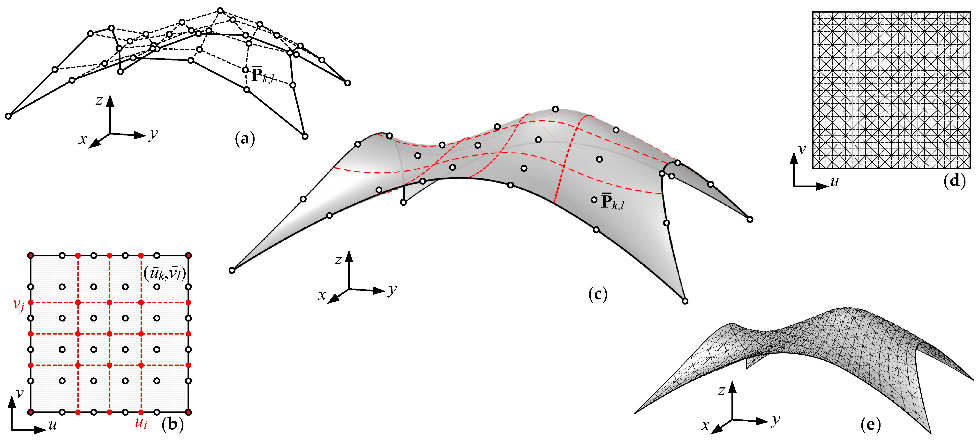
2.1. The Free-Form Surface Model Based on the B-Spline Technique
2.2. The Geometric Representation of the Branching Support Structure Model
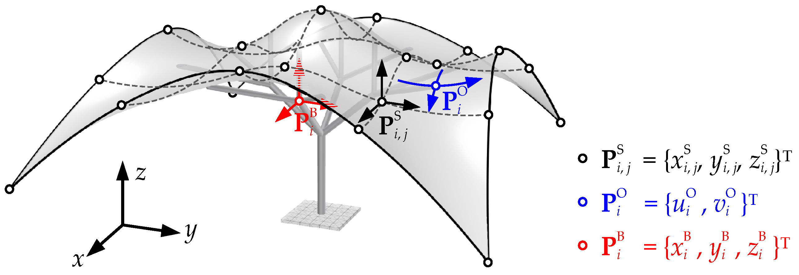
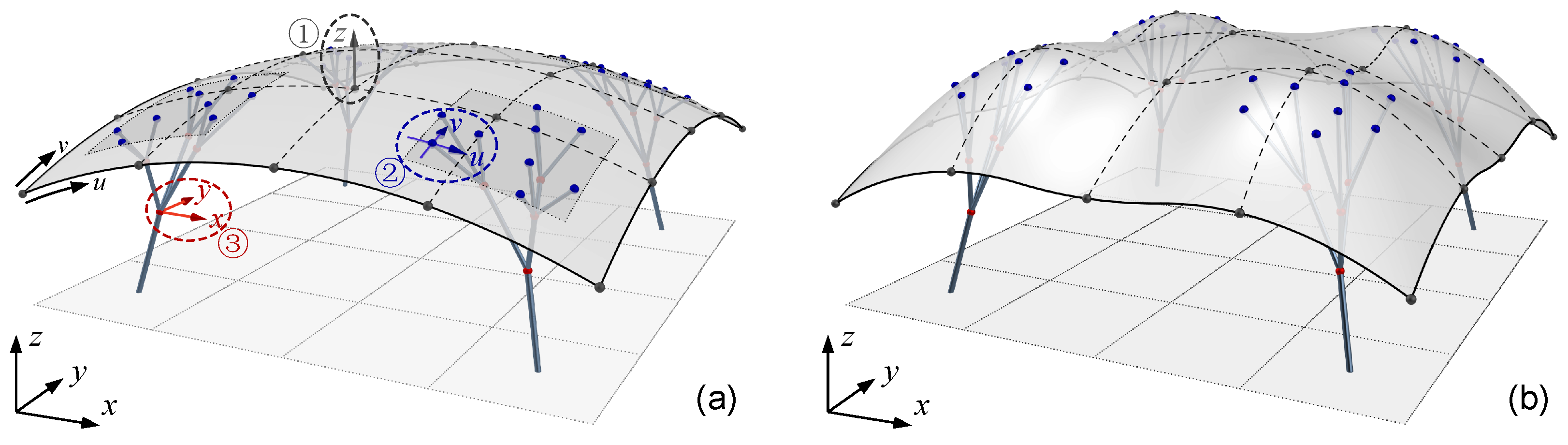
2.3. The Composition of Design Variables for Branch-Supported Free-Form Structure
- (1)
- The physical coordinates PS of the data points of the free-form surface are defined as PS = {PSi, j}, where PSi, j = {xSi, j, ySi, j, zSi, j}T. Adjusting PS in physical space can alter the shape of the surface.
- (2)
- The parameter values PO of the intersection points between the branches and free-form curved roof are defined as PO = {}, where = {, }T. Adjusting PO in parametric space can change the supporting location of the branching structure relative to the upper surface.
- (3)
- The physical coordinates PB of the non-intersection points of the branching structure is defined as PB = {}, where = {, , }T. Adjusting PB in physical space can alter the shape of the branching structure.
3. The Integrated Shape Optimization Method for Branch-Supported Free-Form Surface Structure
3.1. Establishment of the Shape Optimization Method for Branch-Supported Free-Form Surface Structure
3.2. The Sensitivity of Branch-Supported Free-Form Surface Structure
3.2.1. The Partial Derivative of Strain Energy C with Respect to Structural Nodes X
3.2.2. The Partial Derivative of Structural Nodes X with Respect to Design Variables P
- For the design variable ∈ {PS}, moving only affects the surface shape, i.e., {XS, XO}. The partial derivative ∂Xi/∂ can be computed as follows:
- For the design variable ∈ {PO}, assuming that its physical coordinate, obtained through Equation (22), is stored in the finite element model as node Xm, any movement of only affects Xm. The partial derivative ∂Xi/∂ can be computed as follows:
- For the design variable ∈ {PB}, assuming that its coordinate is directly stored in the finite element model as node Xm, any movement of only affects Xm. The partial derivative ∂Xi/∂ can be computed as follows:
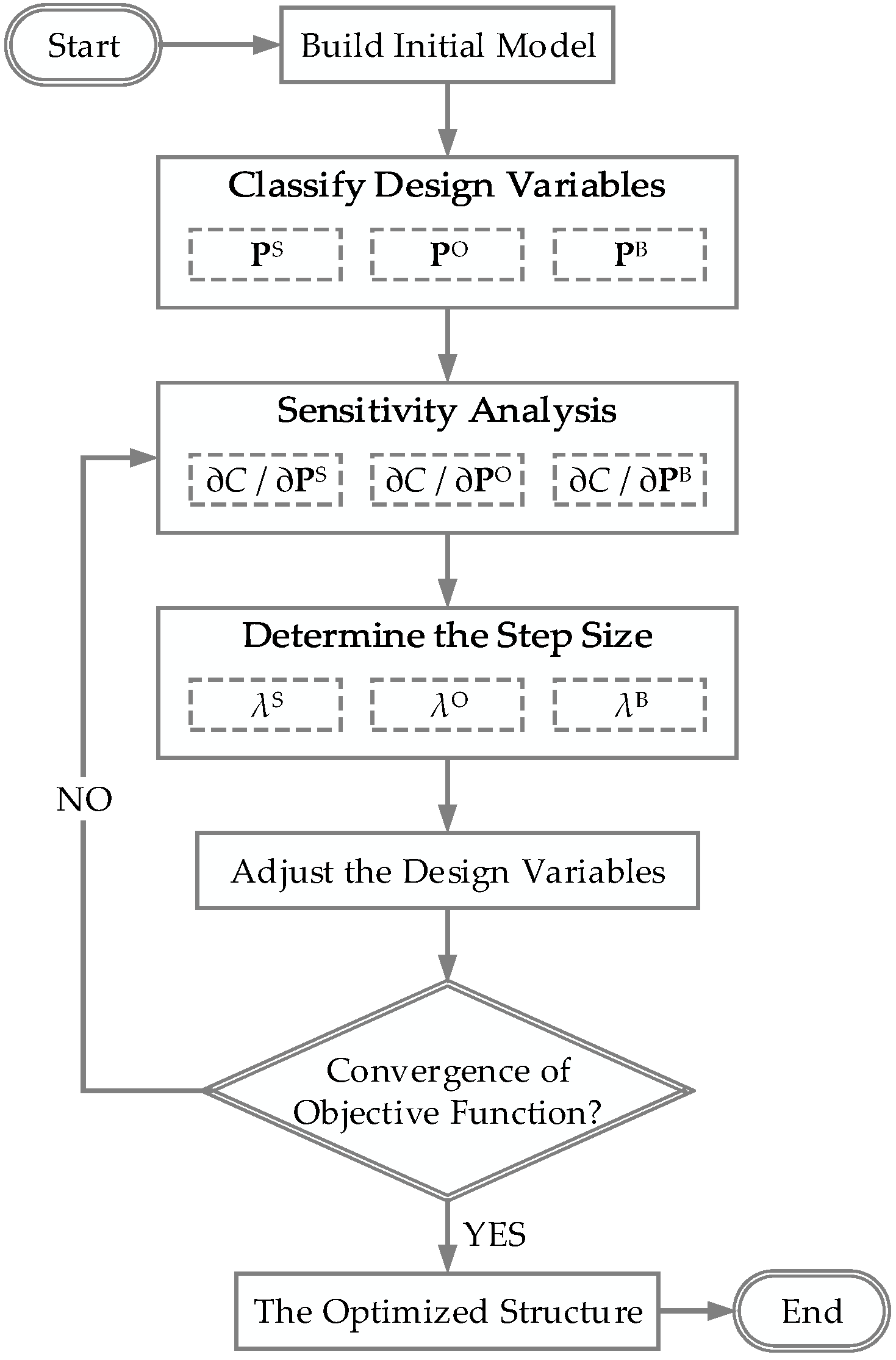
3.3. The Procedure of the Shape Optimization Method for Branch-Supported Free-Form Surface Structure
- (1)
- Build the initial geometric model according to the architectural intention and constraints;
- (2)
- Classify the design variables into three types based on their influence areas;
- (3)
- Calculate the strain energy sensitivity of each design variable according to Section 2.2;
- (4)
- Determine the step size for each type of design variable using Equation (15).
- (5)
- Adjust the design variables using Equation (11).
- (6)
- Repeat steps (3) to (6) until the convergence condition is achieved.
- (7)
- The convergence condition is:
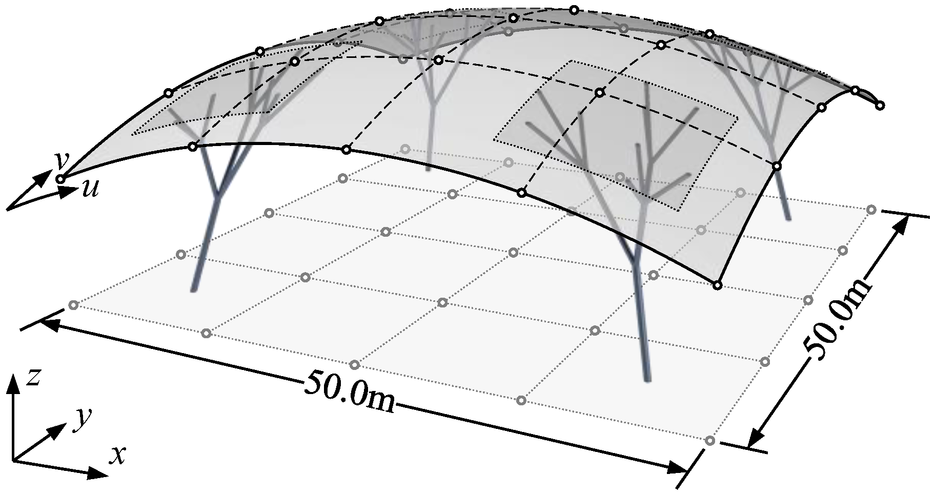
4. Numerical Examples and Discussions
- (1)
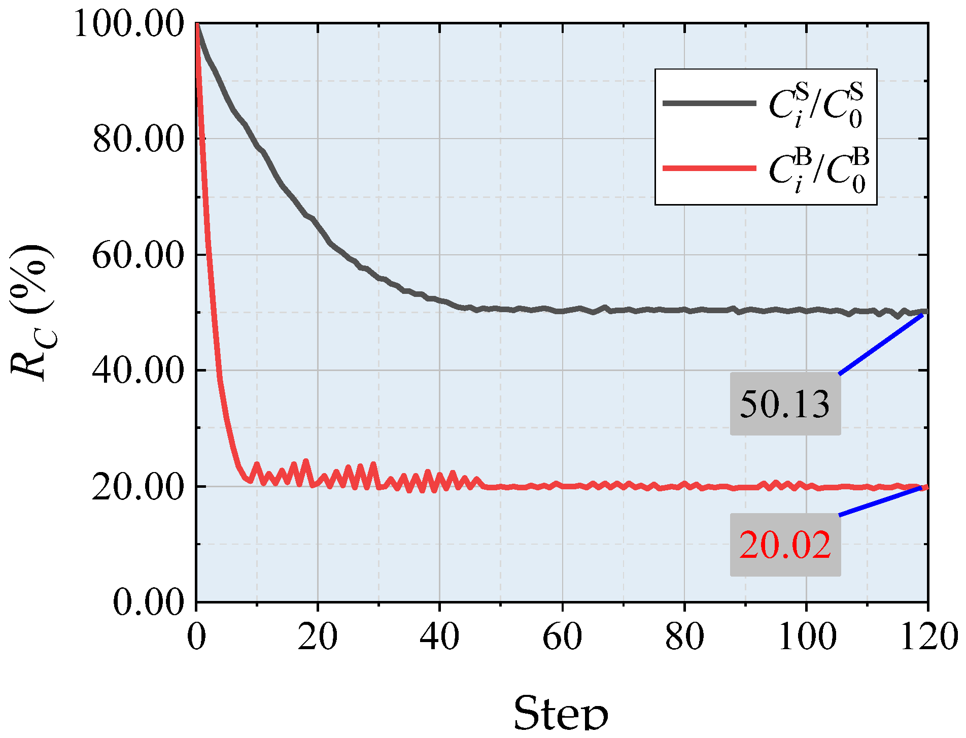
- Ci/C0: Strain energy change rate, measuring the change in structural strain energy;
- (2)
- / and /: Strain energy change rate in the shell and tree-like structures respectively, measuring the change in strain energy of each component in the hybrid structure;
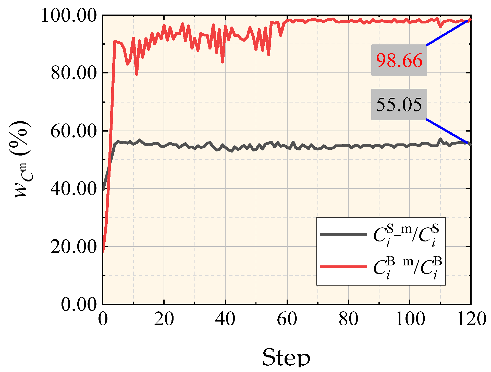
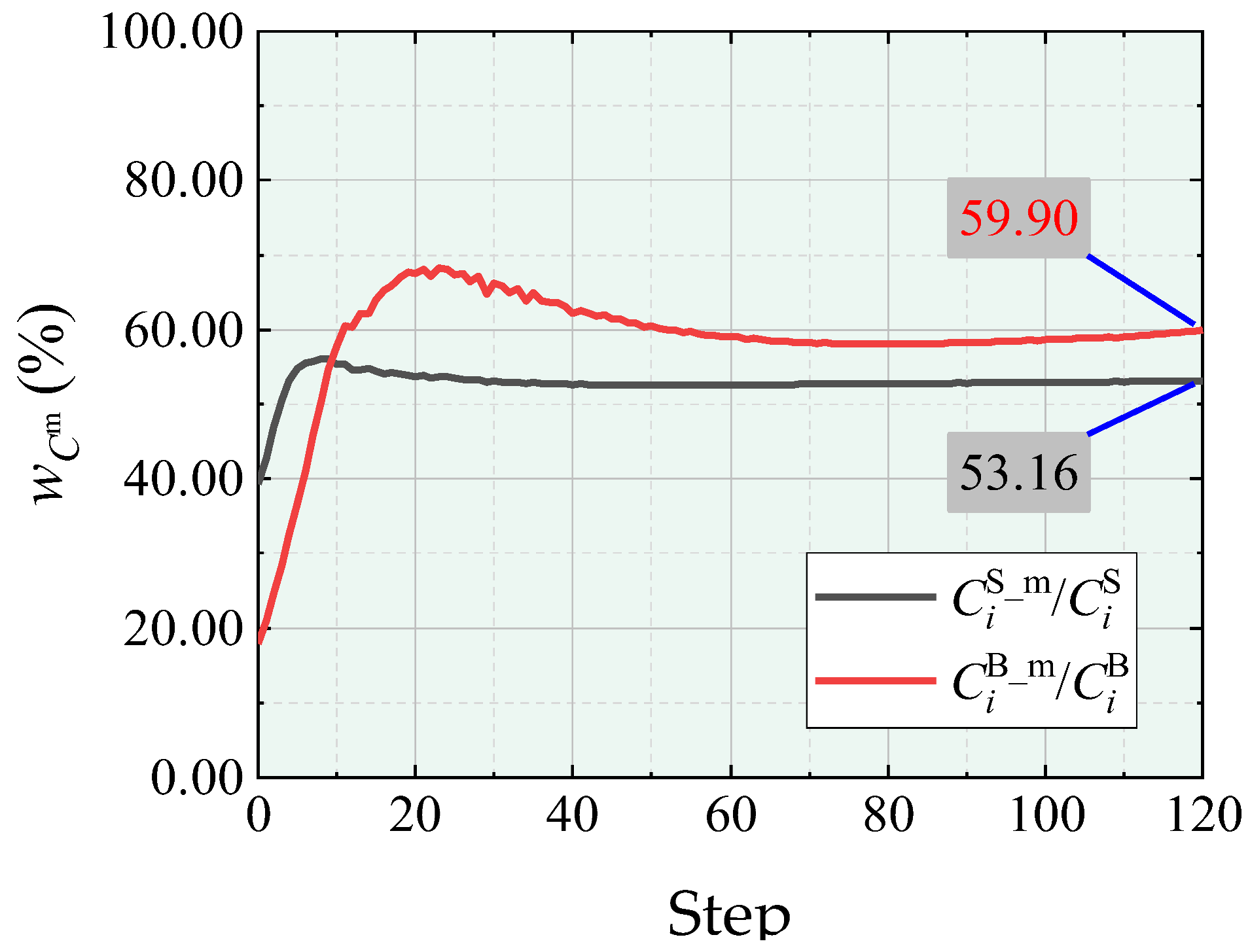
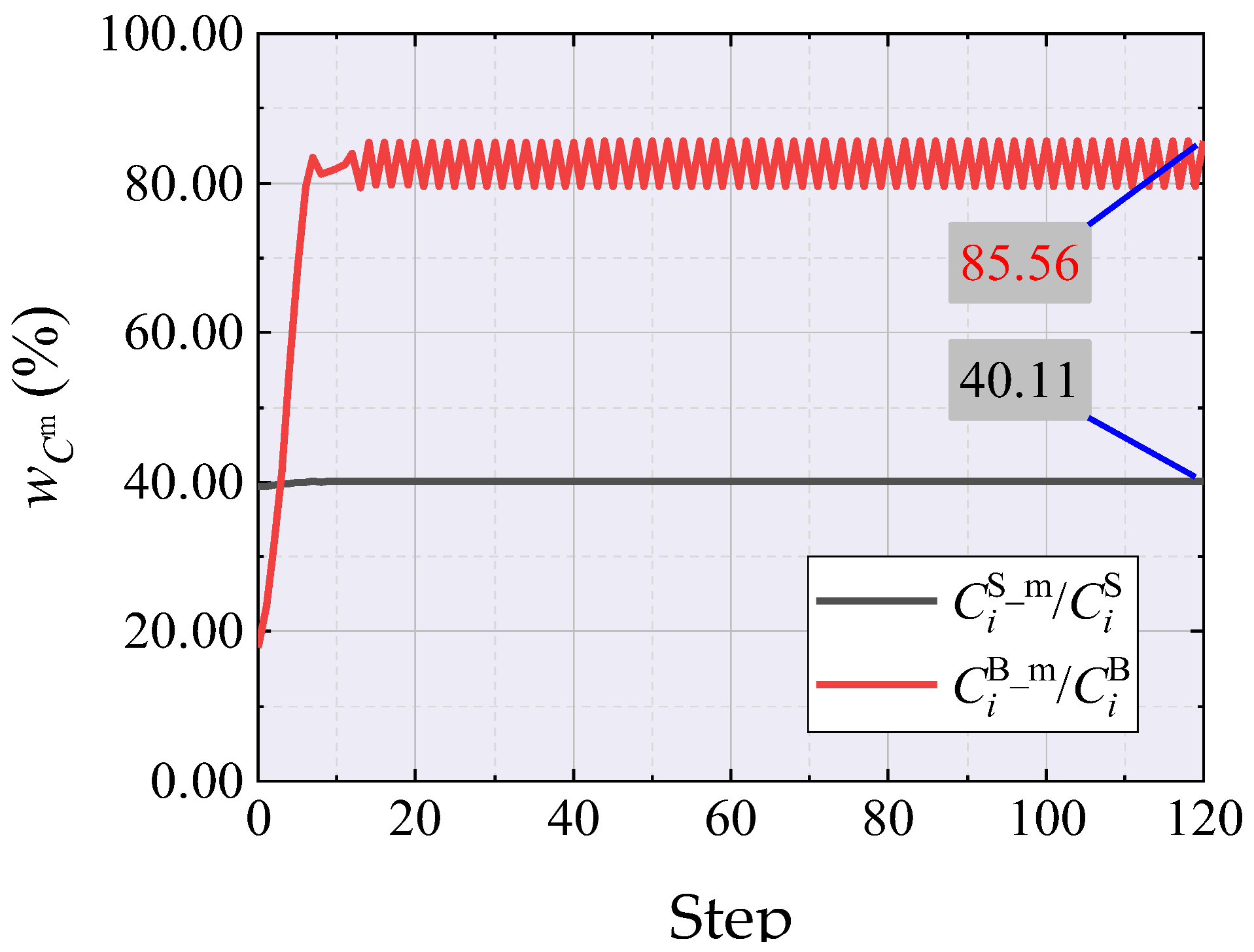
- (3)
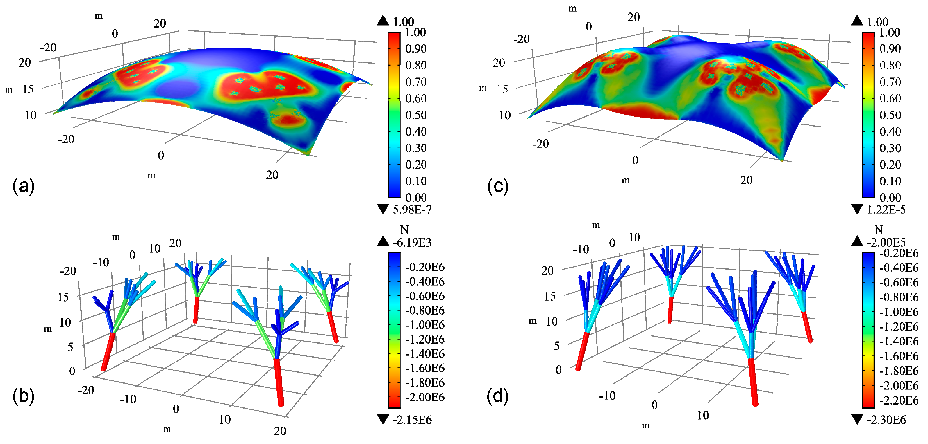
- / and /: Measures the proportion of membrane strain energy and axial force-induced strain energy in the i-th step of the free-form surface shell and tree-like structure, respectively.
5. Conclusions
- (1)
- Based on the theories of B-splines and the rules of branches, the geometric representation of freeform surfaces and tree-like structures has been achieved. The connection between the two is established through parameter space, providing convenience for the preliminary design of buildings.
- (2)
- Compared with the initial structure, the optimized structure relies more on membrane forces and axial forces to transmit loads. For tree-like structures, the distribution of axial forces within the same-level branches becomes more uniform, indicating a more reasonable load distribution of the branching system and effectively avoiding inefficient components. The overall strain energy of the structure decreases significantly, and the stiffness is effectively improved, leading to greatly improved load-bearing performance.
- (3)
- The morphological optimization method, aiming to minimize the overall strain energy of the structure, can fully consider the collaborative load-bearing effect between the upper and lower parts of the tree-like freeform structure. By comparing the optimization results under different adjustment schemes, the more adjustable shape control factors (design variables) there are, the more significant the optimization effect on structural stiffness. Under the premise of meeting the requirements of architecture and structure, different adjustment schemes can provide more references for architectural design.
Author Contributions
Funding
Institutional Review Board Statement
Informed Consent Statement
Data Availability Statement
Conflicts of Interest
References
- Adriaenssens, S.; Block, P.; Veenendaal, D.; Williams, C. Shell Structures for Architecture: Form Finding and Optimization; Routledge: London, UK, 2014. [Google Scholar]
- Kotnik, T.; Schwartz, J. The Architecture of Heinz Isler. J. Int. Assoc. Shell Spat. Struct. 2011, 52, 185–190. [Google Scholar]
- Charleson, A.W. Structure as Architecture: A Sourece Book for Architects and Structural Engineers; Architectural Press: Oxford, UK, 2005. [Google Scholar]
- Rian, I.M.; Sassone, M. Tree-inspired dendriforms and fractal-like branching structures in architecture: A brief historical overview. Front. Archit. Res. 2014, 3, 298–323. [Google Scholar] [CrossRef]
- Özdemïr, N.B.; Selçuk, S.A. Tree Metaphor in Architectural Design. Int. J. Archit. Urban Stud. 2016, 1, 64–76. [Google Scholar]
- Selçuk, S.A.; Gülle, N.B.; Avinç, G.M. Tree-Like Structures in Architecture: Revisiting Frei Otto’s Branching Columns through Parametric Tools. SAGE Open 2022, 12, 1–22. [Google Scholar]
- Block, P.; Ochsendorf, J. Lower-bound Analysis of Masonry Vaults. In Proceedings of the 6th International Conference on Structural Analysis of Historic Construction (SAHC’08), Bath, UK, 2–4 July 2008. [Google Scholar]
- Zhou, J.; Chen, X.; Yu, Y.; Zhou, D.; Li, T.; Guo, Y. Design of the Platform Roof in Changsha New Railway Station. Build. Struct. 2009, 39, 1–4+8. (In Chinese) [Google Scholar]
- Shen, S.; Wu, Y. Structural Morphology and Modern Space Structures. J. Build. Struct. 2014, 35, 1–10. (In Chinese) [Google Scholar]
- Bletzinger, K.U.; Ramm, E. Structural Optimization and Form Finding of Light Weight Structures. Comput. Struct. 2001, 79, 2053–2062. [Google Scholar] [CrossRef]
- Otto, F.; Nerdinger, W.; Meissner, I.; Möller, E.; Grdanjski, M. Frei Otto: Complete Works: Lightweight Construction—Natural Design; Birkhäuser: Basel, Switzerland, 2005; pp. 16–31. [Google Scholar]
- Wu, Y.; Zhang, J.; Cao, Z. Form-finding Analysis and Engineering Application of Branching Structures. J. Build. Struct. 2011, 32, 162–168. (In Chinese) [Google Scholar]
- Hook, R. A Description of Helioscopes, and Some Other Instruments; T.R.: London, UK, 1676; p. 31. [Google Scholar]
- Collins, G.R. Antonio Gaudí: Structure and Form. Perspecta 1963, 8, 63–90. [Google Scholar] [CrossRef]
- Huerta, S. Structural Design in the Work of Gaudí. Archit. Sci. Rev. 2006, 49, 324–339. [Google Scholar] [CrossRef]
- Goldsmith, N. The physical modeling legacy of Frei Otto. Int. J. Space Struct. 2016, 31, 25–30. [Google Scholar] [CrossRef]
- Brühwiler, E. Heinz Isler’s Twin Shell Roof in Deitingen—Preservation of a ‘Timeless Wing Beat’. Proc. Inst. Civ. Eng.-Eng. Hist. Herit. 2021, 174, 133–138. [Google Scholar] [CrossRef]
- Boller, G.; Block, P.; Schwartz, J. Heinz Isler’s Form-finding Models for his “HIB” Shells: Between Experiment and Design. In Proceedings of the Italian Workshop on Shell and Spatial Structures (IWSS 2023), Turin, Italy, 26–28 June 2023. [Google Scholar]
- Liddell, I. Frei Otto and the Development of Gridshells. Case Stud. Struct. Eng. 2015, 4, 39–49. [Google Scholar] [CrossRef]
- Descamps, B. Computational Design of Lightweight Structures: Form Finding and Optimization; John Wiley & Sons, Inc.: Hoboken, NJ, USA, 2014; pp. XI–XXIII. [Google Scholar]
- Schek, H.J. The Force Density Method for Form Finding and Computation of General Networks. Comput. Methods Appl. Mech. Eng. 1974, 3, 115–134. [Google Scholar] [CrossRef]
- Pauletti, R.M.O.; Pimenta, P.M. The Natural Force Density Method for the Shape Finding of Taut Structures. Comput. Methods Appl. Mech. Eng. 2008, 197, 4419–4428. [Google Scholar] [CrossRef]
- Barnes, M.R. Form Finding and Analysis of Tension Space Structures by Dynamic Relaxation. Ph.D. Thesis, University of London, London, UK, 1977. [Google Scholar]
- Argyris, J.H.; Angelopoulos, T.; Bichat, B. A General Method for the Shape Finding of Lightweight Tension Structures. Comput. Meth. Appl. Mech. Eng. 1974, 3, 135–149. [Google Scholar] [CrossRef]
- Su, Y.; Wu, Y.; Ji, W.; Shen, S. Shape Generation of Grid Structures by Inverse Hanging Method Coupled with Multiobjective Optimization. Comput.-Aided Civ. Infrastruct. Eng. 2018, 33, 498–509. [Google Scholar] [CrossRef]
- Zhao, Z.; Yu, D.; Zhang, T.; Zhang, N.; Liu, H.; Liang, B.; Xian, L. Efficient Form-finding Algorithm for Freeform Grid Structures Based on Inverse Hanging Method. J. Build. Eng. 2022, 46, 103746. [Google Scholar] [CrossRef]
- Santos, R.B.; Lopes, C.G.; Novotny, A.A. Structural Weight Minimization under Stress Constraints and Multiple Loading. Mech. Res. Commun. 2017, 81, 44–50. [Google Scholar] [CrossRef]
- Tu, G.; Cui, C.; Zhou, G. Quasi-Mechanism Method of Structural Morphogenesis Based on Self-Adapting Function of Net System. J. Struct. Eng. 2018, 144, 04018205. [Google Scholar] [CrossRef]
- Xia, Y.; Wu, Y.; Hendriks, M.A.N. Simultaneous Optimization of Shape and Topology of Free-form Shells Based on Uniform Parameterization Model. Autom. Constr. 2019, 102, 148–159. [Google Scholar] [CrossRef]
- Cui, C.; Yan, H. A Morphosis Technique for Curved-Surface Structures of Arbitrary Geometries—Height Adjusting Method and its Engineering Applications. Chin. Civ. Eng. J. 2006, 39, 1–6. (In Chinese) [Google Scholar]
- Lin, X.; Wu, Y.; Cao, Z. Computational Morphogenesis Method for Freeform Structures Generated by Translating B-Spline Curves. Adv. Sci. Lett. 2011, 4, 2727–2732. [Google Scholar]
- Ding, C.; Seifi, H.; Dong, S.; Xie, Y.M. A New Node-Shifting Method for Shape Optimization of Reticulated Spatial Structures. Eng. Struct. 2017, 152, 727–735. [Google Scholar] [CrossRef]
- Hassani, B.; Tavakkoli, S.M.; Ghasemnejad, H. Simultaneous Shape and Topology Optimization of Shell Structures. Struct. Multidiscip. Optim. 2013, 48, 221–233. [Google Scholar] [CrossRef]
- Ap, L.; Faia, N.G. Form Finding Techniques of Branched Construction Developed by Frei Otto. J. Int. Assoc. Shell Spat. Struct. 2018, 59, 60–67. [Google Scholar]
- Xu, C.; Wang, Z.; Li, B.; Liu, Q. Form-finding and shape optimization of bio-inspired branching structures based on graphic statics. Structures 2021, 29, 392–407. [Google Scholar] [CrossRef]
- Zhao, Z.; Wu, J.; Yu, D.; Wu, G. Intelligent Design Algorithm for Branching Structures Based on Numerical Inverse Hanging Method. J. Build. Struct. 2022, 43, 86–94. (In Chinese) [Google Scholar]
- Zhao, Z.; Yu, D.; Zhang, T.; Cai, Q. Intelligent Design Algorithm for Branching Structures Based on Updated Force Density Method. J. Build. Eng. 2022, 57, 104858. [Google Scholar] [CrossRef]
- Tu, G.; Chen, C.; Cui, C.; Wang, J. Element-clustered Form-finding Analysis of Tree-like Structures Based on Dynamic Relaxation. J. Build. Struct. 2022, 43, 287–293. (In Chinese) [Google Scholar]
- Tu, G.; Chen, C.; Gong, Z.; Wang, Y. A Form-Finding Method for Branching Structures Based on Dynamic Relaxation. Appl. Sci. 2021, 11, 7165. [Google Scholar] [CrossRef]
- Tu, G.; Chen, C. A Shape-finding Approach of Tree-like Structure Based on Grouping Strategy and Generalized Inverse Matrix Theory. Structures 2021, 29, 1960–1966. [Google Scholar] [CrossRef]
- Huang, X.; Xie, Y.M.; Burry, M.C. Advantages of Bi-Directional Evolutionary Structural Optimization (BESO) over Evolutionary Structural Optimization (ESO). Adv. Struct. Eng. 2007, 10, 727–737. [Google Scholar] [CrossRef]
- Cui, C.; Ohmori, H.; Sasaki, M. Computational Morphogenesis of 3D Structures by Extended ESO Method. J. Int. Assoc. Shell Spat. Struct. 2003, 44, 51–61. [Google Scholar]
- Wang, D. Optimal shape design of a frame structure for minimization of maximum bending moment. Eng. Struct. 2007, 29, 1824–1832. [Google Scholar] [CrossRef]
- Peng, X. Structural Topology Optimization Method for Morphogenesis of Dendriforms. Open J. Civ. Eng. 2016, 6, 526–536. [Google Scholar] [CrossRef]
- Piegl, L.; Tiller, W. The NURBS Book, 2nd ed.; Springer: Berlin/Heidelberg, Germany, 1995. [Google Scholar]

| Structure | Node Number | Type * | Coordinate | Link Number | Link |
|---|---|---|---|---|---|
 | 1 | NXPT | (−8.0, −8.0, 0.0) | 1 | (1, 2) |
| 2 | NXPT | (−8.3, −8.3, 3.9) | 2 | (2, 3) | |
| 3 | NXPT | (−9.9, −8.4, 7.1) | 3 | (2, 4) | |
| 4 | NXPT | (−8.4, −9.9, 7.0) | 4 | (2, 5) | |
| 5 | NXPT | (−7.5, −7.5, 7.9) | 5 | (3, 6) | |
| 6 | XPT | (0.97, 1.36) | 6 | (3, 7) | |
| 7 | XPT | (1.05, 1.65) | 7 | (3, 8) | |
| 8 | XPT | (1.23, 1.45) | 8 | (4, 9) | |
| 9 | XPT | (1.36, 0.97) | 9 | (4, 10) | |
| 10 | XPT | (1.45, 1.23) | 10 | (4, 11) | |
| 11 | XPT | (1.65, 1.05) | 11 | (5, 12) | |
| 12 | XPT | (1.52, 1.52) | 12 | (5, 13) | |
| 13 | XPT | (1.58, 1.79) | 13 | (5, 14) | |
| 14 | XPT | (1.79, 1.58) |
| No. | I | II | III | IV | ||||||||
|---|---|---|---|---|---|---|---|---|---|---|---|---|
| Scheme * | PS | PO | PB | PS | PO | PB | PS | PO | PB | PS | PO | PB |
| ● | ● | ● | ● | ○ | ○ | ○ | ○ | ● | ○ | ● | ● | |
| Ci/C0 | 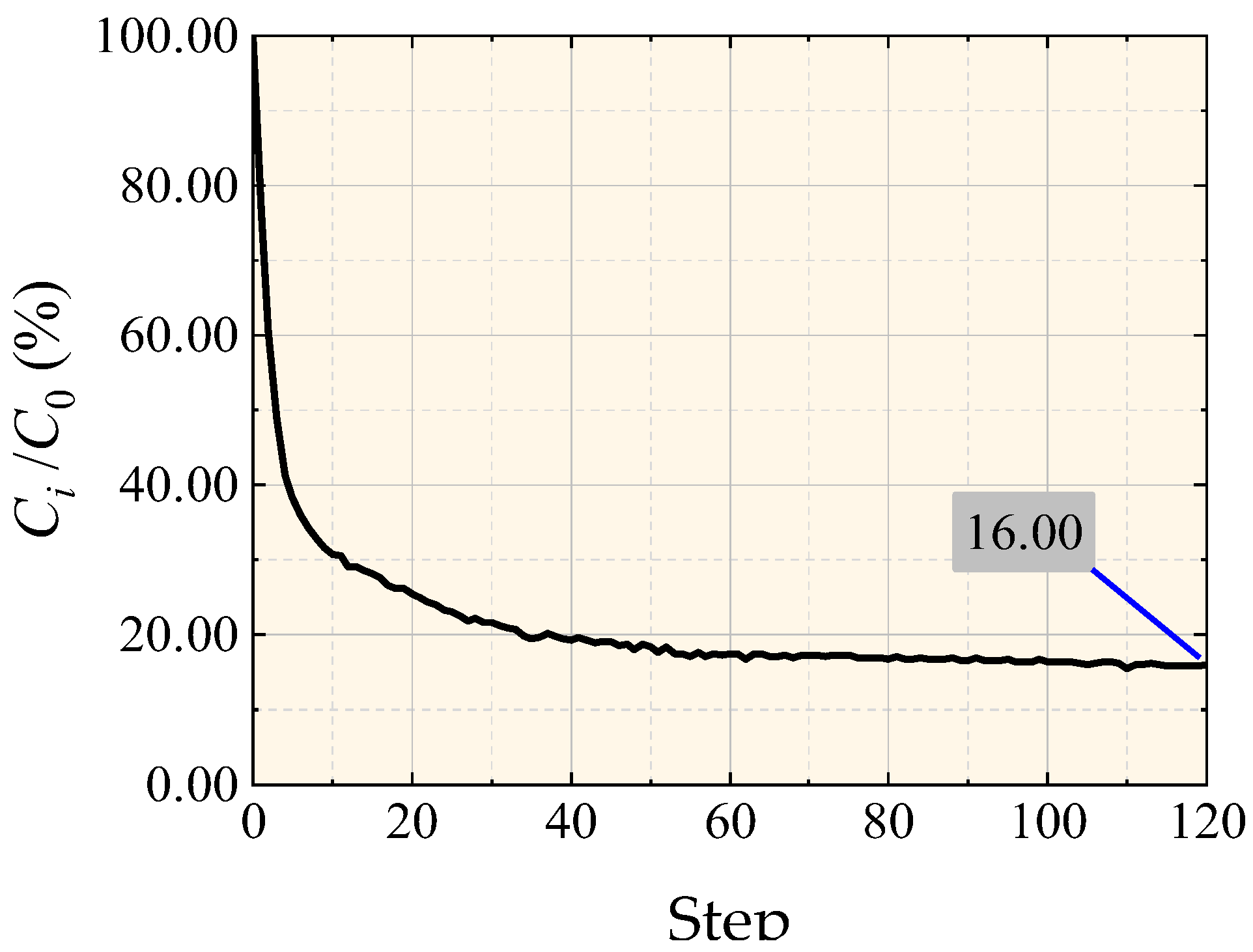 | 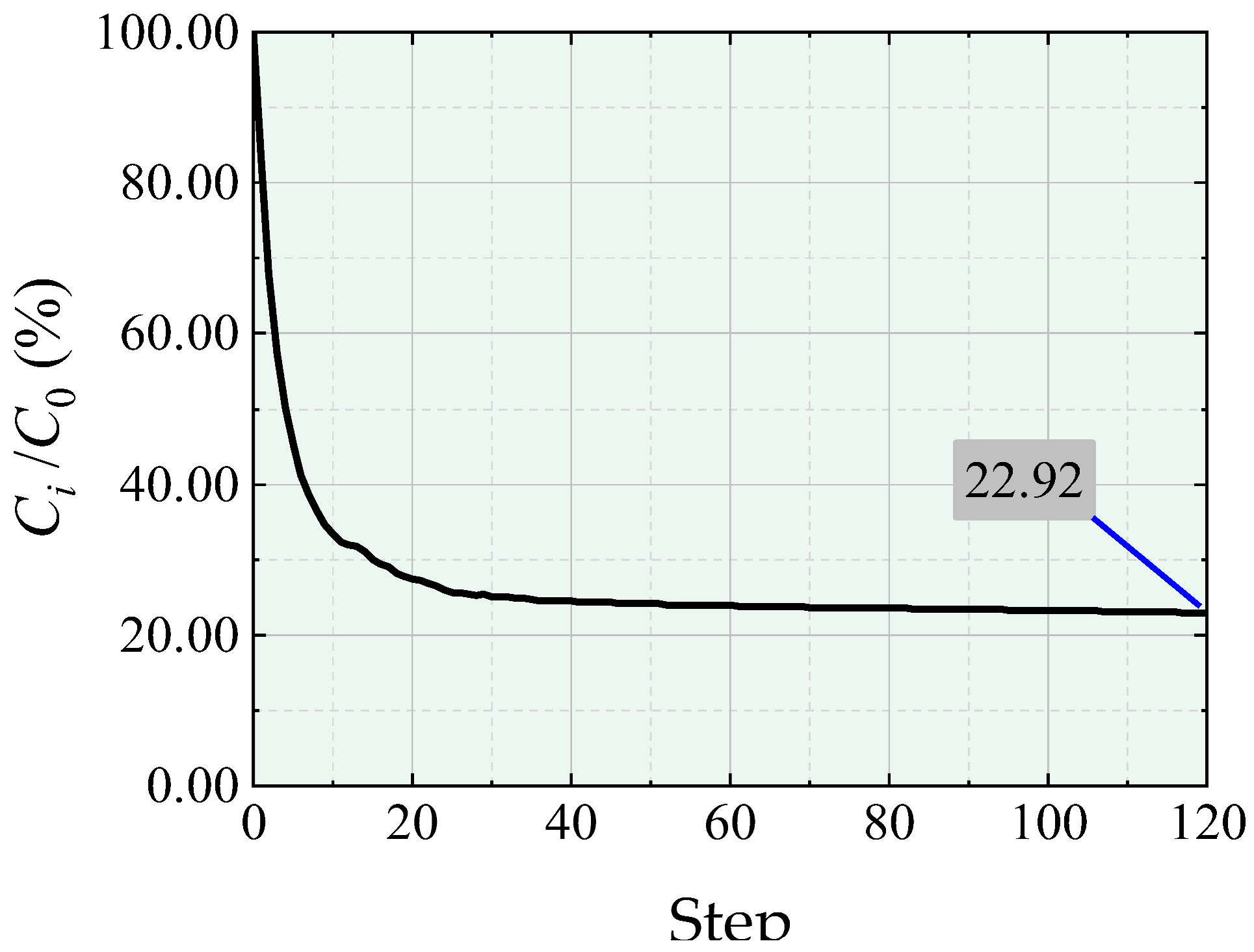 | 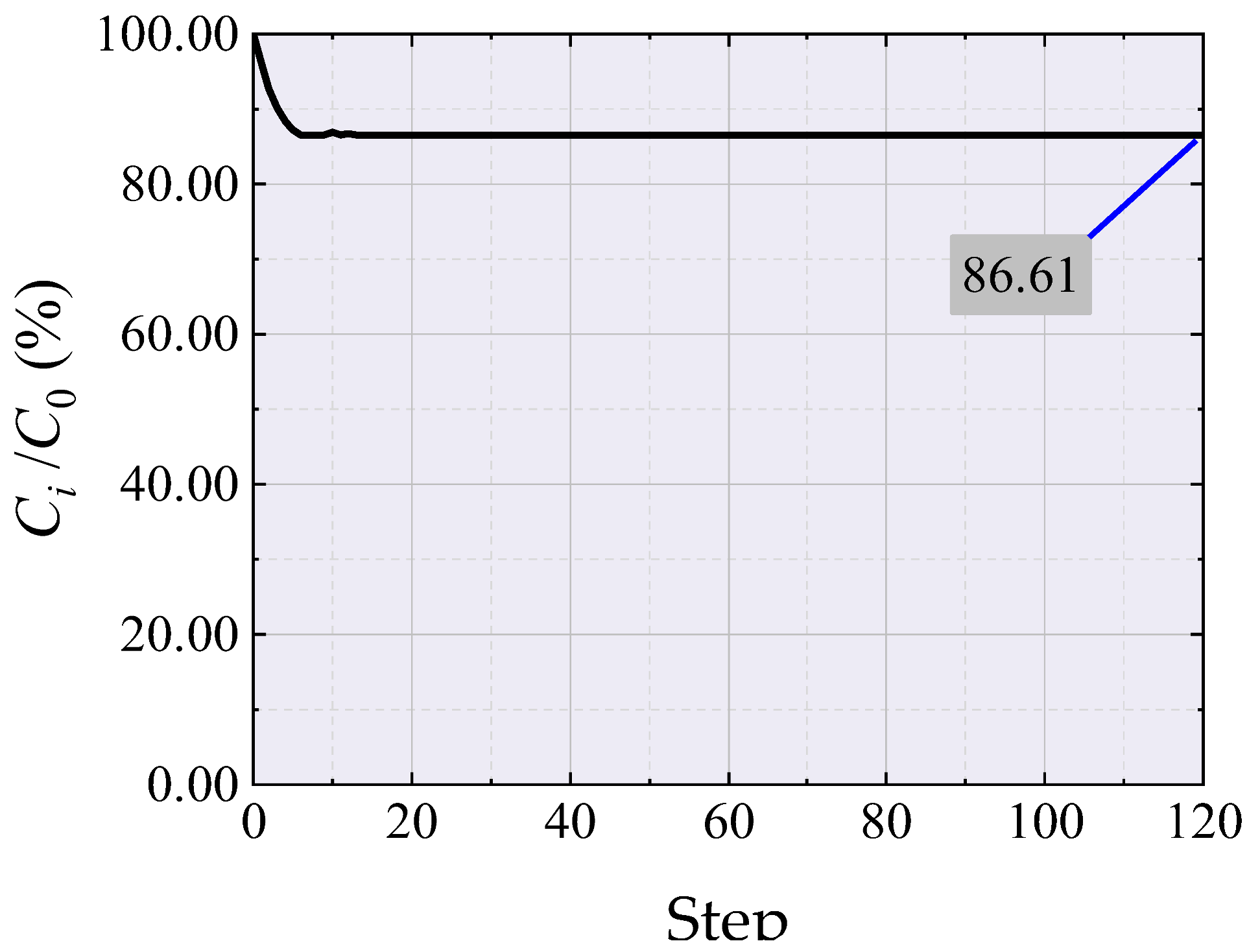 | 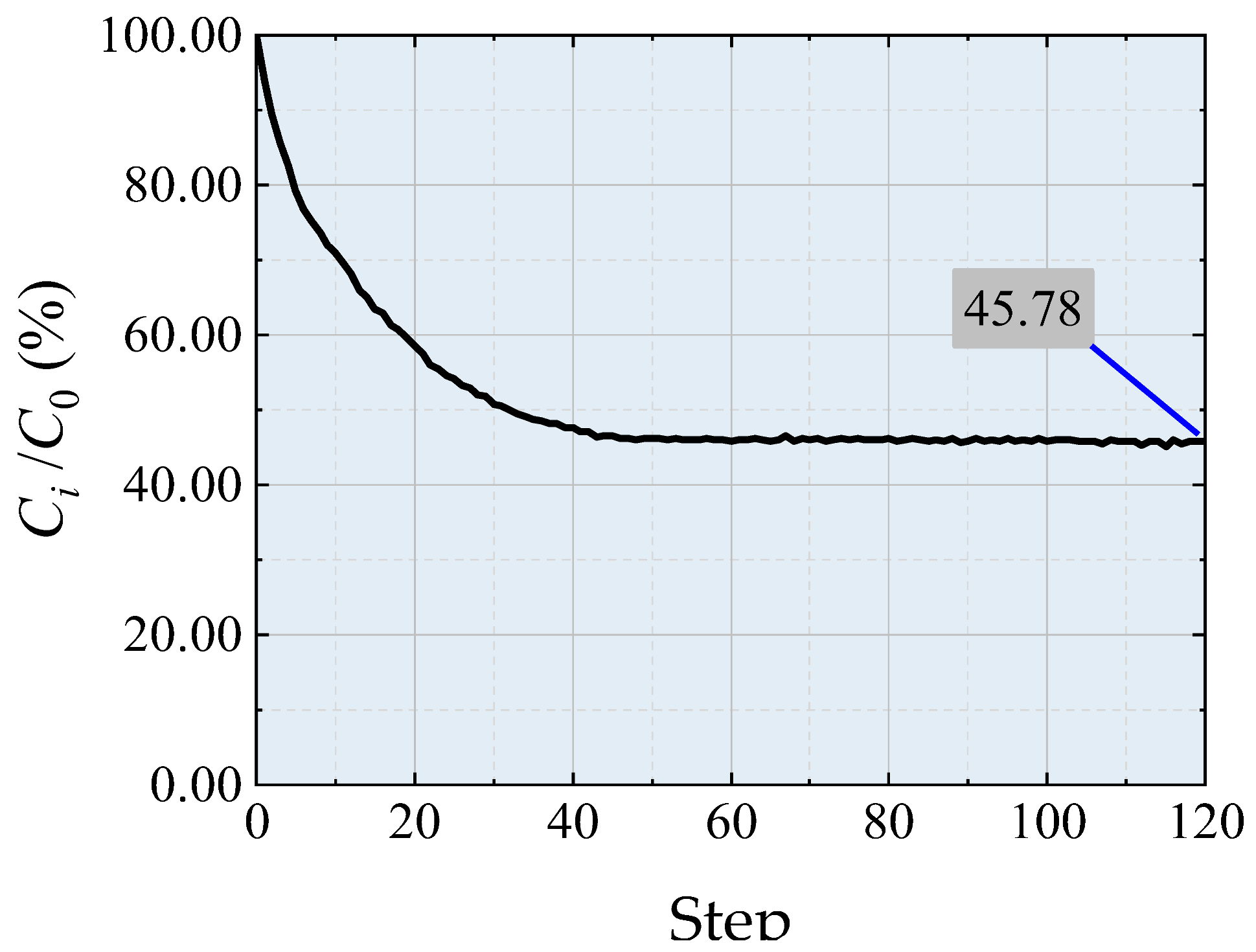 | ||||||||
| / / |  | 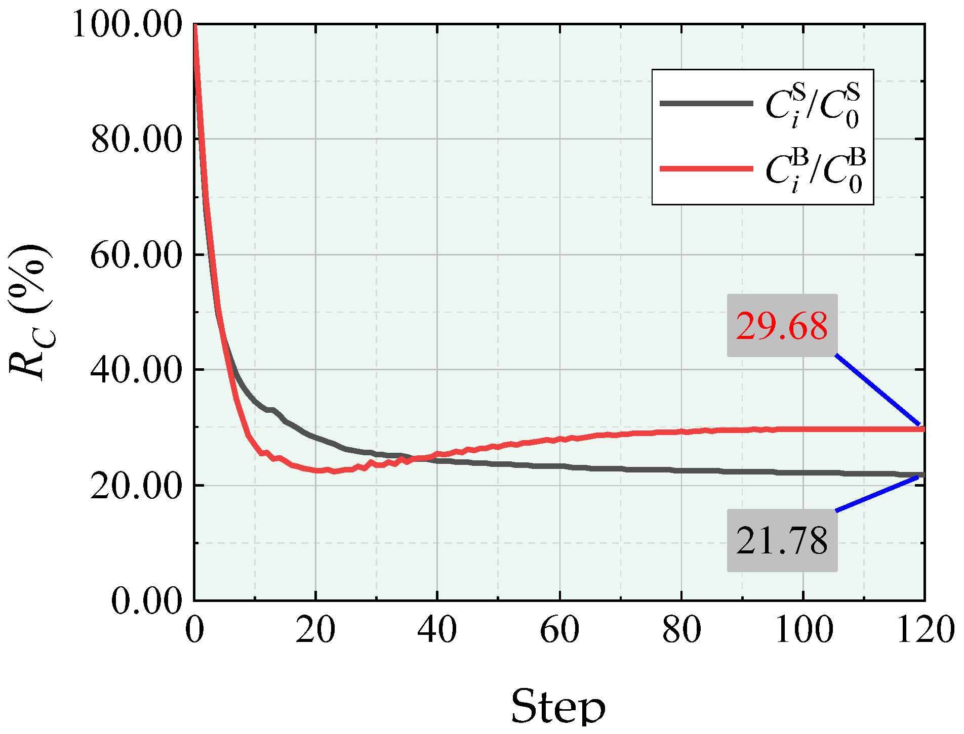 | 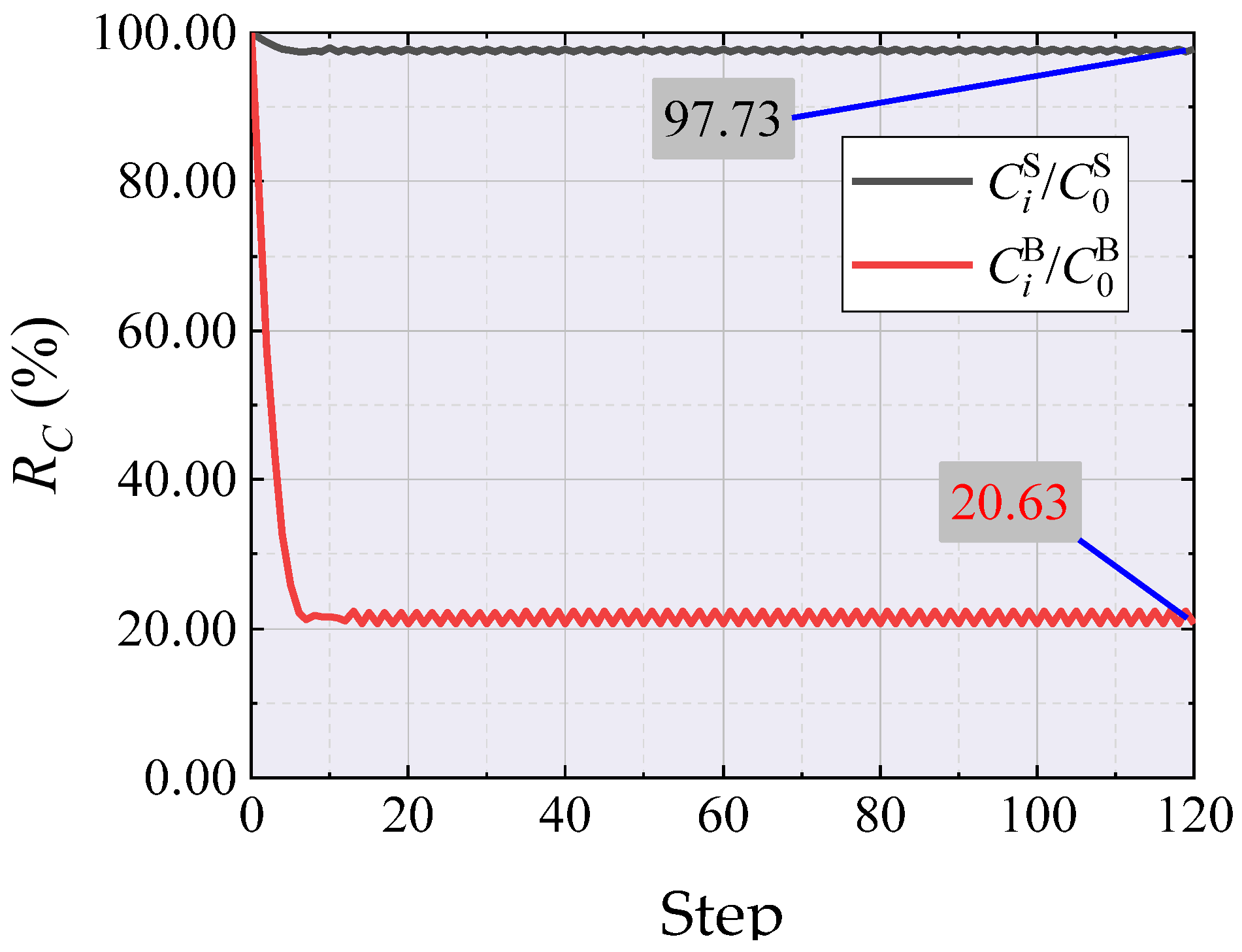 |  | ||||||||
| / / |  |  |  |  | ||||||||
| Final Shape | 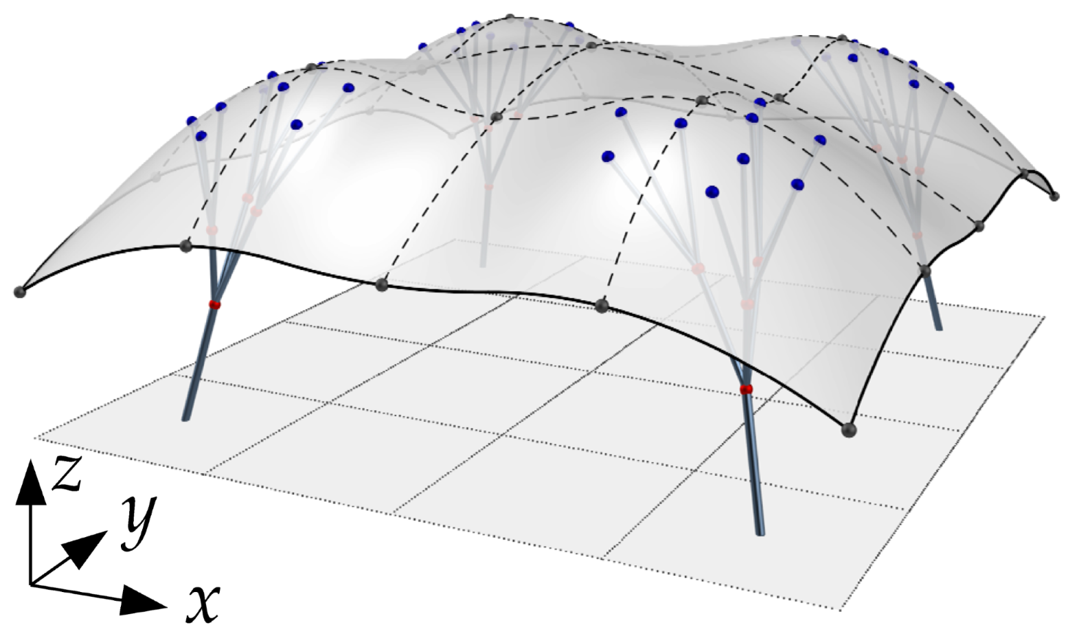 | 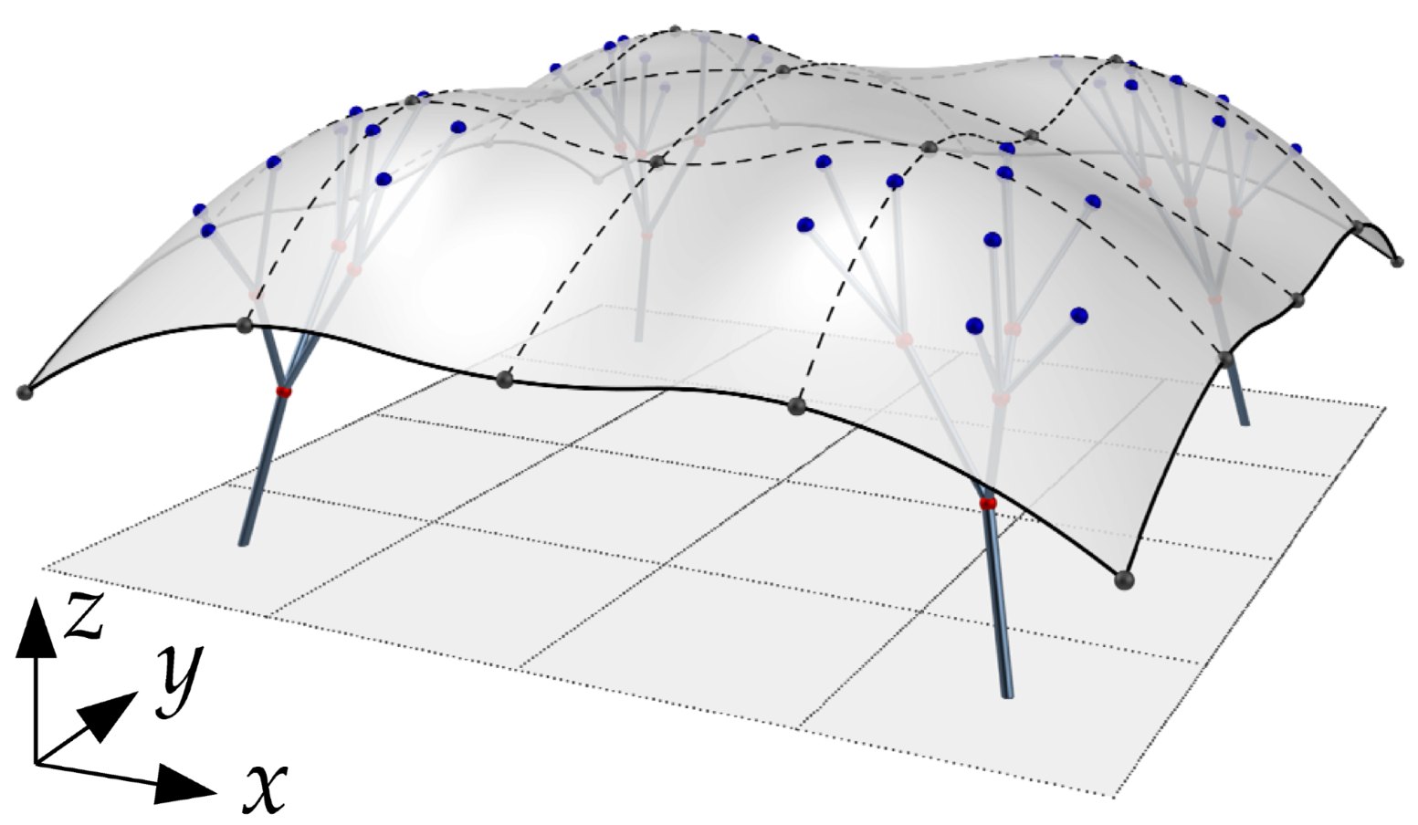 | 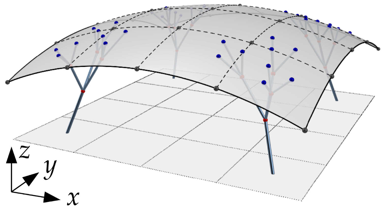 | 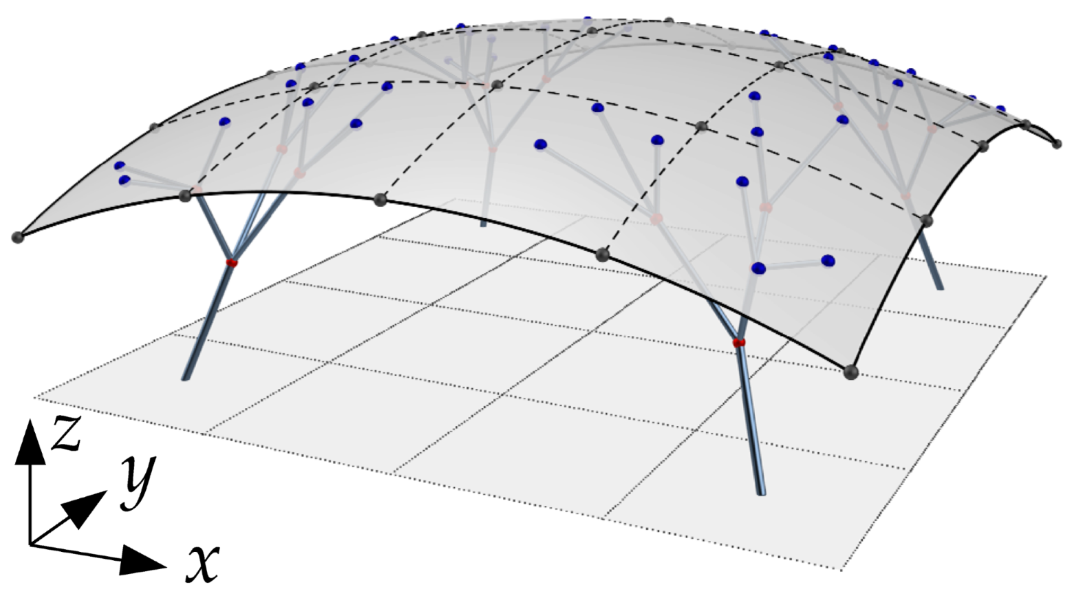 | ||||||||
Disclaimer/Publisher’s Note: The statements, opinions and data contained in all publications are solely those of the individual author(s) and contributor(s) and not of MDPI and/or the editor(s). MDPI and/or the editor(s) disclaim responsibility for any injury to people or property resulting from any ideas, methods, instructions or products referred to in the content. |
© 2023 by the authors. Licensee MDPI, Basel, Switzerland. This article is an open access article distributed under the terms and conditions of the Creative Commons Attribution (CC BY) license (https://creativecommons.org/licenses/by/4.0/).
Share and Cite
Wang, J.; Cui, C.; Jiang, B. An Integrated Shape Optimization Method for Hybrid Structure Consisting of Branch and Free-Form Surface. Appl. Sci. 2024, 14, 334. https://doi.org/10.3390/app14010334
Wang J, Cui C, Jiang B. An Integrated Shape Optimization Method for Hybrid Structure Consisting of Branch and Free-Form Surface. Applied Sciences. 2024; 14(1):334. https://doi.org/10.3390/app14010334
Chicago/Turabian StyleWang, Jianghong, Changyu Cui, and Baoshi Jiang. 2024. "An Integrated Shape Optimization Method for Hybrid Structure Consisting of Branch and Free-Form Surface" Applied Sciences 14, no. 1: 334. https://doi.org/10.3390/app14010334