Abstract
The purpose of this study is to determine the material properties of CFRP composites in the form of a fabric for the construction of racing car bodywork. This work focused on the determination of the strength and tribological properties as well as investigating the effects of the operating environment on the developed material. Three material variants, differing in the number of layers used to produce the reinforcement, were used in this study. The tests were carried out on two-/three-/four-layer sheets produced by infusion. Due to the later use of the tested composites for the sheathing of a racing car, the results obtained were analysed in terms of the most favourable strength properties while keeping the weight as low as possible. In this study, the hardness, impact strength, and tensile and bending stresses of the developed composites were examined. In addition to the strength properties, the density, the effects of immersion in water, and the composite’s resistance to staining and friction in the presence of aggressive media were also checked. The structure and the breakthroughs resulting from the strength tests were observed using a stereoscopic microscope. The material’s resistance to sunlight and UVB was also tested.
1. Introduction
Throughout history, from the first successful vehicle designs to the present day, various construction materials such as steel, aluminium, and other metals and their alloys have been used in the construction of means of transport. For several years now, there has been a noticeable increase in the use of composite materials in the automotive industry. The reason for this is the properties of composites. They are distinguished by their relatively low weight and high mechanical strength. Composite materials can be easily shaped and, after production, usually have high stiffness. The development of composites has enriched the design possibilities of modern constructions and enabled virtually unlimited possibilities for shaping their functional properties [1].
The first body made of composites (glass–fibre-reinforced polymer) was for the Chevrolet Corvette, presented at the Motorama show in New York in 1953. In motorsports, the use of carbon-fibre-reinforced polymers was introduced in Formula 1, in the McLaren MP4 car [2].
Current materials engineering in the automotive industry is increasingly replacing metal (solid) parts with polymer matrix composites in order to reduce vehicle weight and increase fuel economy. The response of composite materials to compressive forces is opposite to that of traditionally used metallic materials. Most composites have a brittle rather than ductile response to the indicated loads. Metallic structures collapse under crushing, impact by buckling, and/or fold in an accordion fashion with extensive plastic deformation. In composite materials, on the other hand, mechanisms occur, such as fibre fracture, matrix fracture, and delamination of fibres with the matrix. The actual damage mechanisms and sequence are highly dependent on the geometry of the structure and the orientation and alignment of the fibres. Therefore, it is important to properly design the composite material structure in order to obtain a system with the highest possible energy absorption [3,4].
Fei Cheng et al. introduced an innovative approach for designing carbon-fibre-reinforced plastic (CFRP) laminated structures, combining the asymptotic homogenisation method with ply optimisation. The method involved calculating the equivalent mechanical properties of a single-layer CFRP using asymptotic homogenisation. Ply optimisation was carried out in three stages: initial free-size optimisation for ply shapes and patch locations per ply orientation, final size optimisation for ply thicknesses, and final ply stacking sequence optimisation. Applying this method to a body-in-white model floor reduced its mass by 60%, demonstrating its efficiency in investigating laminated structures and its potential for lightweight automobile component design and analysis [5].
Vehicle safety in frontal collisions often relies on energy-absorbing crash boxes attached to the front side member (FSM). Recent attention has turned to advanced polymer composites in these crash boxes. Soo-young Choi’s study assessed conventional metallic crash boxes through tests and simulations, comparing them to CFRP composite materials. The results show that CFRP composite crash boxes outperform aluminium ones by 1.5 times, especially when considering lamination for compression failure. Moreover, larger inner diameters with the same shell thickness reduce energy absorption, and inadequate 0°-oriented layer content degrades performance as inner diameters increase [6].
Correlations between impact energy and damage, specifically delamination area and matrix effects, in CFRP laminates under foreign object damage conditions at extreme temperatures were shown in Kwang-Hee Im’s article. The research highlighted the brittleness of CFRP laminates under dynamic loading, emphasising the importance of studying their impact behaviour. Impact-induced damage, especially delamination and matrix cracking, was scrutinised with consideration of different stacking sequences and matrices. The study found that temperature variations significantly impacted delamination areas, with effects observed in both CF/EPOXY and CF/PEEK laminates. Results indicated that at extreme temperatures, the delamination areas decreased with increasing temperature. Linear relations between impact energy and delamination areas were observed under low-/high-temperature conditions [7].
The Uthaman et al. study focuses on evaluating the ageing process of epoxy resin and its carbon-fibre-reinforced polymer (CFRP) composites when subjected to water, acidic, and alkaline solutions at various temperatures. The Arrhenius theory is employed to predict the service life of CFRP composites under different conditions. Analysis indicates that CFRP composites are particularly vulnerable to degradation in acidic environments. Scanning electron microscopy reveals damage and degradation of the polymer matrix. Consequently, to ensure extended application, it is recommended that CFRP composites be safeguarded against exposure to acidic environments. Their study sheds light on the durability, ageing, and potential improvements of CFRP composites, crucial for their successful application in engineering [8].
Sabina Alessi et al. delve into the impact of hydrothermal ageing at 30 °C and 70 °C on the delamination behaviour of CFRP laminates. Their study aims to reconcile conflicting trends in fracture energies induced by water ageing. Utilising a high Tg model epoxy matrix, they prepare consistent bulk resin samples and CFRP panels for testing. Significant mass uptake in CFRP, indicating water absorption at the fibre/matrix interface, is observed. Dynamic mechanical thermal analysis (DMTA) uncovers plasticisation effects, while high-temperature ageing leads to cross-linking density heterogeneity. Despite increased chain mobility, aged, neat resin maintains fracture toughness. The stability of Mode I delamination energy in aged composites suggests a balance between toughening and embrittling mechanisms. High-temperature ageing exacerbates fibre/matrix degradation but leads to denser bridging and reduced crack growth behaviour [9].
The effect of heat exposure during short ageing periods on carbon-fibre-reinforced polymer (CFRP) composites was described in Merino Perez et al.’s work. Impact energy absorption and tensile strength tests were conducted after subjecting the composite to different ageing temperatures for various time intervals. The overall composite properties were minimally affected. Ageing time had no significant influence, while viscoelastic properties increased up to the glass transition temperature (Tg) due to post-curing and decreased at higher temperatures due to matrix damage. This study aims to understand how heat during machining impacts CFRP composites, finding that short, high-temperature ageing intervals do not greatly affect strength and impact energy absorption. The impact of ageing temperature on these properties is small, but a decrease is observed around Tg, followed by an increase. Tensile strength increases up to Tg due to post-curing, then decreases at higher temperatures due to further damage [10].
Olusanmi Adeniran et al. explore how environmental factors, particularly temperature and relative humidity, influence the mechanical performance of additive manufacturing (AM)-fabricated CFRP composites. Through testing under warm–wet, warm–dry, and cold–dry conditions, they compare the mechanical properties of samples tested under standard ambient conditions post-fabrication. Results show minimal effects of warm temperatures but significant alterations in material properties at near-zero cold temperatures after short-term exposure. Their study underscores temperature’s dominance over humidity in influencing mechanical properties, with dry conditions enhancing material properties slightly under warm conditions, while wet conditions have negligible impact. These findings highlight the intricate relationship between environmental conditions and the mechanical behaviour of AM-fabricated CFRP composites, guiding their optimisation for real-world applications across diverse industries [11].
Feras Korkees et al. delve into addressing CFRPs’ vulnerability to impact damage and moisture absorption by proposing graphene incorporation for improved mechanical properties and moisture resistance. Their study investigates NH2-functionalised graphene-modified CFRP composites, analysing their flexural properties and diffusion characteristics across varying environmental conditions. Initial findings show reduced flexural strength and modulus with graphene addition, exacerbated by post-impact delamination and cracking. While graphene slows diffusion, it compromises flexural properties due to poor bonding. Although GNPs/CFRP samples do not boost strength, they exhibit enhanced moisture resistance. Challenges persist with NH2-GNPs, lowering flexural strength and underscoring the need for enhanced bonding. Post-curing reduces flexural properties but slows diffusion, suggesting GNPs’ potential for moisture mitigation despite bonding challenges. Further research into manufacturing methods and GNP functionalisation is vital for maximising graphene-enhanced CFRP composites [12].
In Jian Shi et al.’s study, the impact damage resistance of recycled carbon-fibre-reinforced polymer (CFRP) composites was investigated through low-velocity impact and compression after impact (CAI) tests. They analysed the relationships among load, force, and time to understand the damage characteristics of three types of composite laminate: virgin CF-reinforced polymer (V-CFRP), recycled CF-reinforced polymer (R-CFRP), and treated recycled CF-reinforced polymer (TR-CFRP). By examining ultrasonic c-scanning, photography, and scanning electron microscopy (SEM), significant differences were observed in impact shape, area, and mode of damage. V-CFRP exhibited superior impact damage resistance with less damage, higher residual strength, and a greater shear failure angle compared to R-CFRP. Surface cleaning improved damage resistance up to 80% of V-CFRP, while R-CFRP reached only 50%. SEM analysis revealed reduced delamination in TR-CFRP compared to R-CFRP. This study demonstrates that recycled composites can match the low-velocity impact response of virgin composites, paving the way for their widespread use in various applications [13].
The Xuhong Qiang et al. study investigates the impact of two innovative fireproof coatings on the fire resistance of carbon-fibre-reinforced polymer (CFRP) composite sheets. After fire exposure, the post-fire flexural performance of CFRP sheets coated with these fireproof coatings is evaluated through three-point bending tests. Results show a remarkable up to 80% reduction in post-fire flexural properties for CFRP sheets without coatings. However, those coated with fireproof coatings demonstrate significant enhancement. Under large-space fire conditions, coatings of at least 25 mm thickness provide fire-resistance durations exceeding 2 h, meeting specific fire-resistance class requirements. Similarly, under standard fire conditions, coatings of 35 mm thickness meet relevant fire-resistance class requirements [14].
The present article describes a comprehensive project that involved multiple interconnected tasks. It began with fabricating three unique configurations of test sheets using advanced vacuum infusion technology, ensuring precise control over their properties. Subsequently, the project focused on cutting specimens with standardised dimensions from these sheets for subsequent testing phases. This study examined the strength properties of a carefully chosen configuration before and after ageing tests, providing insights into its durability over time. Additionally, the investigation explored the material’s resistance to staining. These tasks collectively aimed to provide a holistic understanding of the material’s characteristics, performance, and suitability for intended applications. The project’s multidimensional approach offers valuable insights into the material’s behaviour under varied conditions, contributing to informed decision-making and potential engineering improvements.
The aim of this study is to determine the material properties of lightweight multilayered carbon-fibre-reinforced polymer matrix composites in the form of a fabric for the construction of a Formula Student class car bodywork. This study focuses on determining the strength as well as examining the effects of the operating environment on the developed material. Due to the later use of the tested composites for constructing the bodywork of a Formula Student car, the types of tests and their conditions were chosen to reflect the possible operating conditions in such a vehicle.
This research conducted on the developed multilayer materials aimed to determine the material properties of carbon-fibre-reinforced composites. Three material variants differing in the number of layers used in reinforcement production were utilised for this study: two-/three-/four-layer sheets produced by infusion. Preliminary tests were conducted for all developed configurations of reinforcing layers. Based on density analysis, it was found that the number of reinforcement layers does not directly affect the density of the final composite or the absorbency of the applied fabric. The material was uniformly impregnated with a resin-hardener mixture for all test series. The use of reinforcement increases the hardness of the composite by about 17% compared to the pure matrix, regardless of the number of layers used. With the addition of another layer of reinforcement to the two-layer composite, the following increase was observed: the average impact strength (by about 20% between successive configurations), the average flexural stress (while increasing the number of reinforcement layers by 50% and 33%, respectively), and the value of the Young’s modulus (by about 35% between successive configurations). The average tensile stress increases by about 37% with the addition of a third layer of reinforcement. However, there is no significant difference in the obtained stress values between the three- and four-layer configurations. Therefore, the main study was conducted for three-layer sheets, which had the best ratio of strength properties to density. This article describes the detailed results of the research conducted specifically for the three-layer material.
2. Composite under Consideration
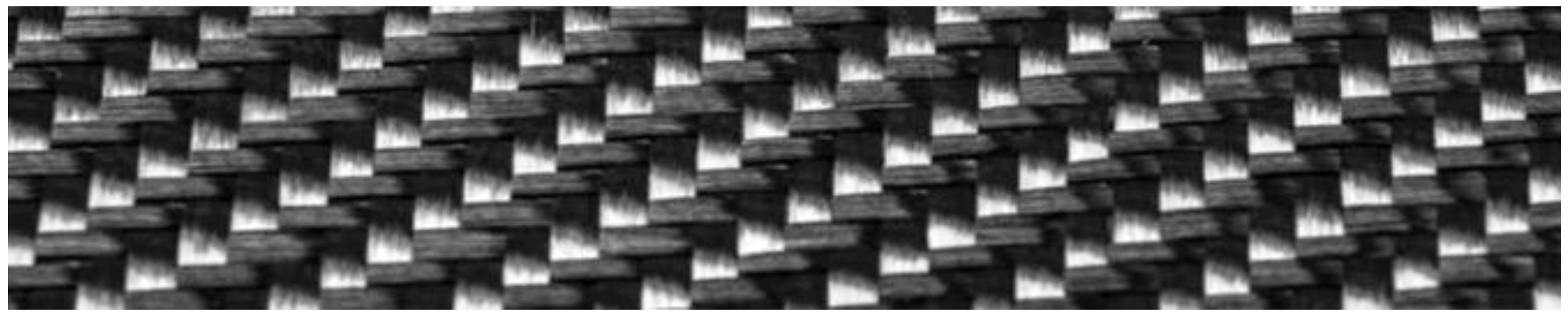
The composite under consideration is based on the application of a carbon fabric reinforcement with the trade name CC 200 T-120 (C-L, Gliwice, Poland) shown in Figure 1, whose technical parameters are included in Table 1.

Figure 1.
CC 200 T-120 carbon fabric.

Table 1.
Technical characteristics of carbon fabric CC 200 T-120 [*].
An epoxy resin with the trade name C-L F80 (C-L, Gliwice, Poland) from the C-L FLOW epoxy system for infusion, light RTM, and other processes requiring a low-viscosity system was used as the matrix. The resin was cured with the amine hardener C-L FH60 (C-L, Gliwice, Poland), allowing the system to be cross-linked very quickly in approximately 60 min. The basic material properties of the resin and hardener are shown in Table 2.
Table 2.
Properties of F80 resin and FH60 hardener [*].
3. Preparation of the Samples
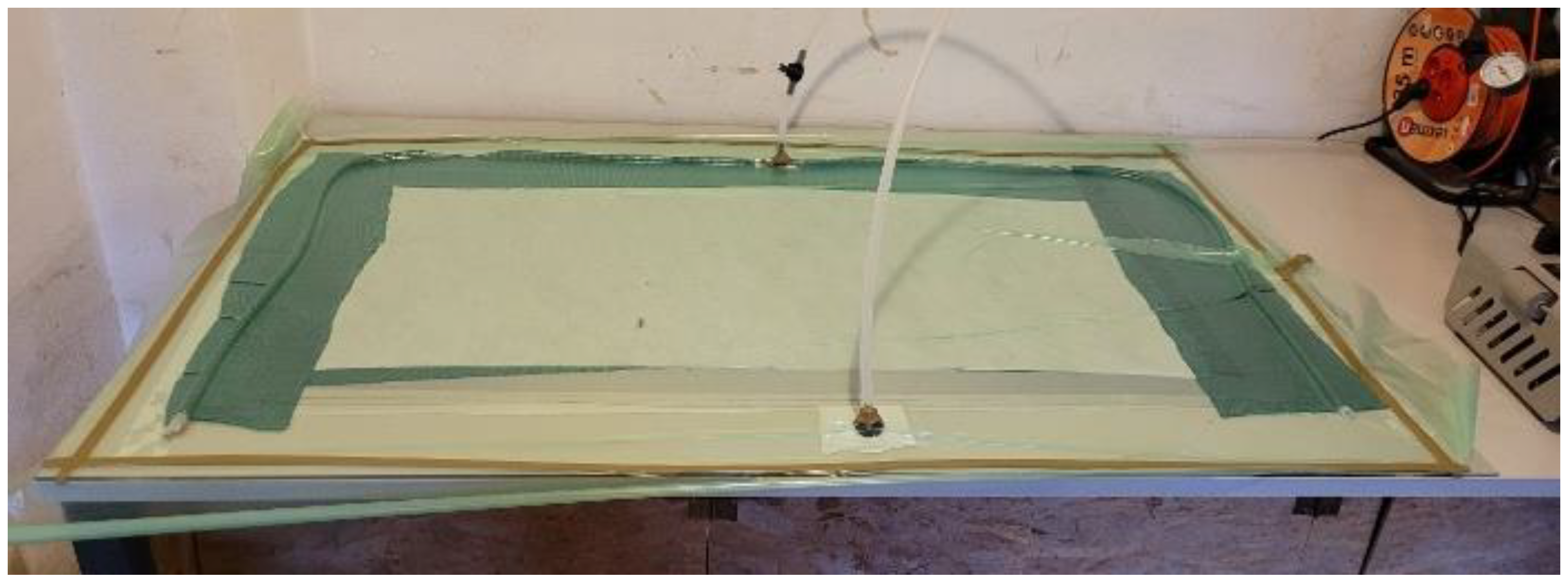
A sheet tested was made from the reinforcement and a resin/hardener mixture (using infusion as a lamination technique). The lamination process started by applying a layer of release agent to the mould to avoid possible sticking of the sheets. LOCTITE FREKOTE 770-NC (Henkel, Düsseldorf, Germany) was used as the release agent. It was applied according to the manufacturer’s specifications in six coats. In a further step, an appropriate number of layers of reinforcement were laid “dry”. This was followed by the application of the remaining layers enclosing the mould: a delamination to facilitate the removal of the vacuum system from the sheet after curing, an infusion mesh to allow even distribution of the resin/hardener mixture throughout the sheet, and a felt mat to absorb excess resin. A vacuum system was applied to the part thus constructed. The spiral tubes through which the resin will flow into the laminated sheet were laid out, as well as the infusion valve and vacuum valve. The vacuum bag was placed on the assembly, pressing it against the butyl tape sealing the assembly and pushing the pins of the vacuum valve and infusion valve through it. The vacuum system was connected, allowing a vacuum between the bag and the glass sealed with butyl tape. Once the vacuum was switched on, the system was checked for leaks, and any leaks were sealed with additional butyl tape. The resulting pressure differential allowed the resin mixed with the hardener to be drawn in and impregnate the constructed part, as shown in Figure 2. The laminated part was left under vacuum for a period of 8 h to ensure that the resin was properly distributed and cured. The curing schedule of the laminates was provided by the material supplier.
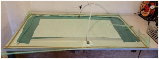
Figure 2.
Laminating process of an example test sheet using the vacuum infusion technique.
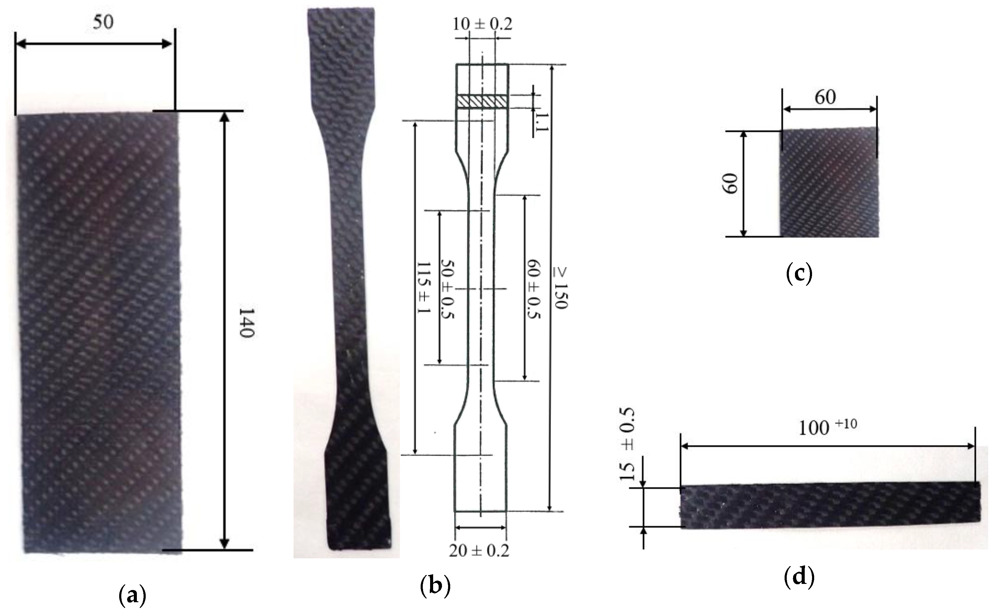
Specimens of standardised dimensions were cut by a laser cutter from the laminated sheets after seasoning for a period of 14 days at ambient temperature. Examples of test specimens are shown in Figure 3. The specimens were cut in one direction due to the use of a 2/2 twill fabric, which is characterised by a repetitive diagonal pattern, using the same number (2) of warp and weft threads in both directions. The composite samples had non-standardised thicknesses, averaging 1.1 mm for a three-ply sheet.

Figure 3.
Examples of test specimens (with dimensions): (a) resistance of staining to friction; (b) tensile; (c) determination of the effects of immersion in water–water absorption; (d) bending.
4. Performed Tests and Conditions
As part of the research work, several tests were performed to determine the material properties of the developed composite structures. Preliminary tests were performed for samples with two, three, and four reinforcing layers. These tests included the determination of density, hardness, impact strength, tensile strength, and three-point bending strength. The determination of these properties was used to select the most favourable configuration from the point of view of the best strength while keeping the weight of the finished laminate as low as possible. The selected configuration turned out to be a laminate with three layers of reinforcement. For this laminate, specific tests were carried out, which included a test for the material’s resistance to staining and ageing and a test for resistance to solar radiation and UVB radiation. In addition, the external surface was observed using a stereoscopic microscope. The results of these tests are presented in this article.
4.1. Hardness Test
The hardness of the tested composite materials was determined using the ball indentation method described in PN EN ISO 2039-1:2004 [15]. This method consists of pressing a ball into the test piece for 30 s under a defined, standardised load. A test force of Fm = 358 N was used for the measurements.
4.2. Tensile Strength Measurement
The tensile strength of the tested composites was determined according to the following standards: ISO 527-1:2019 [16] and ISO 527-4:2023 [17]. The fittings used were 1B, with a test section length of 50 mm. The specimens were conditioned for 24 h under normal conditions (23 ± 2 °C/50 ± 5% RH) before testing, and the thickness and width of the specimens were measured with a micrometer before being fixed in the machine. The test was performed on an Instron 4467 tensile testing machine by stretching the specimens at a constant speed of 10 mm/min. The quantities measured in this test are the deformation (elongation), the deforming force, and the absolute elongation (Lt), i.e., the difference between the final and initial length of the specimen’s measuring section.
4.3. Flexural Strength Measurement
The flexural strength of the tested composites was determined according to ISO 14125:1998/Amd 1:2011 [18] and PN-EN ISO 178: 2019-06 [19]. The bending properties of the material under load in a three-point arrangement (method A) were determined. Class IV fittings (unidirectional and multidirectional composites—carbon fibre systems) with a specimen length of 100 mm and a width of 15 mm were subjected to a static bending test. The standardised support span used in the test was 80 mm. The test was carried out using an Instron 4467 testing machine at a test speed of 2 mm/min. The specimens were conditioned under normal conditions for 24 h before testing. The thickness and width of the specimens needed for the calculations were measured using a micrometer.
4.4. Frictional Colour Fastness Test
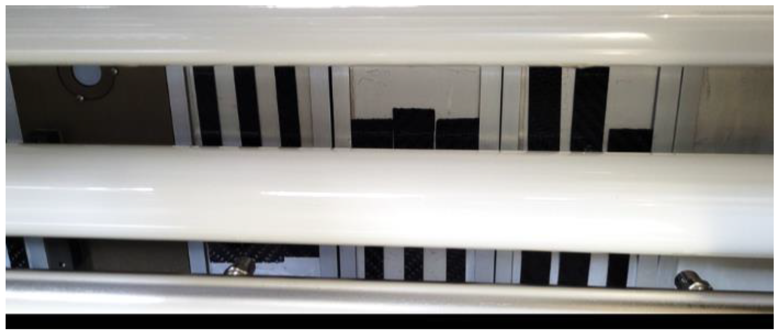
The test for frictional colour fastness was carried out according to ISO 105-X12:2016 [20]. The configurations of the specimen placement on the instrument before the test is started are shown in Figure 4.
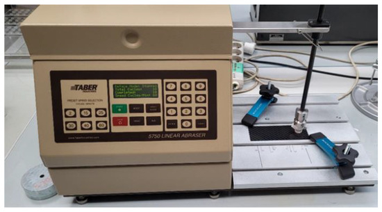
Figure 4.
Placing the sample on the machine before starting the friction staining test.
The 50 × 140 mm test plates were conditioned under normal conditions for 4 h before the test. The samples were rubbed dry and wet with a special cloth, using, in addition to demineralised water, other operating fluids typically used in cars: gear oil, brake cleaner, brake fluid, G48 radiator fluid, and battery acid (37% H2SO4). The section over which the samples were rubbed was 104 ± 3 mm. The rubbing rate is one rubbing cycle per second, back and forth, 20 times (10 times in one direction and 10 times in the other direction) with a force of 9 ± 0.2 N. These values are defined by the test standard. They make it possible to determine the total rubbing distance, which in the case in question was approximately 2.1 m.
Microscopic observations were made using a Leica DVM6 stereo microscope (Polymed Polska, Warsaw, Poland), which allows spatial observation of the magnified object. The external surface of the specimens was observed at 80× magnification to determine the quality of manufacture. The microscope was also used to observe the breakthroughs resulting from the strength tests carried out at magnifications ranging from 15× to 60×.
4.5. Solar Resistance Test
The solar resistance test (xenon arc lamp test-XWO) was performed according to DIN EN ISO 4892-2:2013-06 [21]. This method involves determining the resistance of products to artificial light, simulating natural daylight passing through window glass with unequivocal heat. The test was performed according to method A, cycle 4 (Table 3) in the Xenon Weather-Ometer Ci 4400 (Figure 5). The test used an internal and external filter system: Boro S. The exposure period was 500 h. This time is to simulate the operation of the material in a temperate environment for six months.
Table 3.
Ageing conditions for cycle 4 of method A.
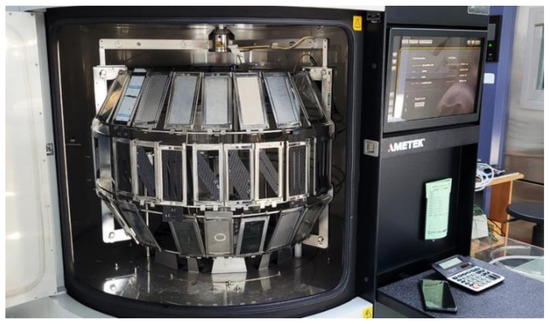
Figure 5.
Samples mounted in the device during the solar resistance test (tested under the light of an arc xenon lamp).
4.6. UV Resistance Test
The UV resistance test was performed according to ISO 4892-3:2016-04 [22]. In the case of the test material, the UV resistance (UVB-313 fluorescent lamps (Klimatest, Wroclaw, Poland)), was determined using method B-cycles no. 5. One test cycle (12 h) was conducted according to the following parameters [8]:
- -
- Sunlight period UVB fluorescent lamp 313 type 2 (40 W): 8 h;
- -
- Temperature of the black plate: 50 ± 1 °C (deviation from the standard: in the standard 70);
- -
- Light irradiance: 0.48 W/m2;
- -
- UVB-free condensation period: 4 h at 50 ± 1 °C on black tile.
Deviation from the standard: the lower temperature of the black tile is due to the thermal strength of the cured product (without annealing), which, according to the technical data sheet of the epoxy system used in the samples, is between −10 and 50 °C. Therefore, the temperature of the black plate was reduced so as not to tighten up the test too much. The test was performed on an Atlas UV Tester (Klimatest, Wroclaw, Poland), which is a UV fluorescence test instrument that allows simultaneous condensation of the samples under selected atmospheric conditions. The appearance of the specimens during the test is shown in Figure 6. Initially, the test specimens were planned to be exposed to UVB light for 36 cycles (432 h), but due to the strong degradation of the resin observed, it was decided to reduce the duration of the test to 24 cycles (288 h).

Figure 6.
Samples mounted in the device during UV resistance testing.
4.7. Gloss Measurement
Before and after the assumed exposure time during both ageing tests, the gloss on the test samples was measured using a micro-TRI-gloss BYK gloss meter. The measurement procedure is described in EN ISO 2813:2014 [23]. Before each measurement, the gloss meter was calibrated according to the values shown on the calibration certificate. Gloss was always measured at an angle of 60 degrees, which is the midpoint of the values allowed by the standard and is suitable for gloss testing on all types of surfaces, from matte to semi-matte to glossy.
4.8. Effects of Immersion in Water
The study of the effects of immersion in water was conducted according to the methodology described in ISO 175:2010 [24]. The effects of immersion in water were determined on samples measuring 60 × 60 mm, cut from a three-layer sheet. Water absorption was determined by immersing the samples in water for a period of seven days at a temperature of 23 ± 2 °C and 70 ± 2 °C in an inert container made of plastic. The mass of the samples was measured before immersion, immediately after removal (after drying with paper towels), and after additional drying at 50 °C for 2 h.
5. Test Results
During the tests for individual measurements, 10 readings were taken, from which five outliers were plotted. Based on the remaining five results, the measurement uncertainty was calculated. For the test results obtained, the expanded uncertainty of the mean value was calculated using the Student–Fisher method of determining the errors of a small series of measurements, category A, at a confidence level of α = 0.95, which is a typical value in laboratory practice. The values of these measurements for the individual results throughout this work are given as values ± after the calculated mean results.
5.1. Ageing Tests
Table 4 presents the average gloss measurement results for the samples made from the three-ply laminate before and after the ageing tests, together with the calculated gloss loss.
Table 4.
Gloss measurement results.
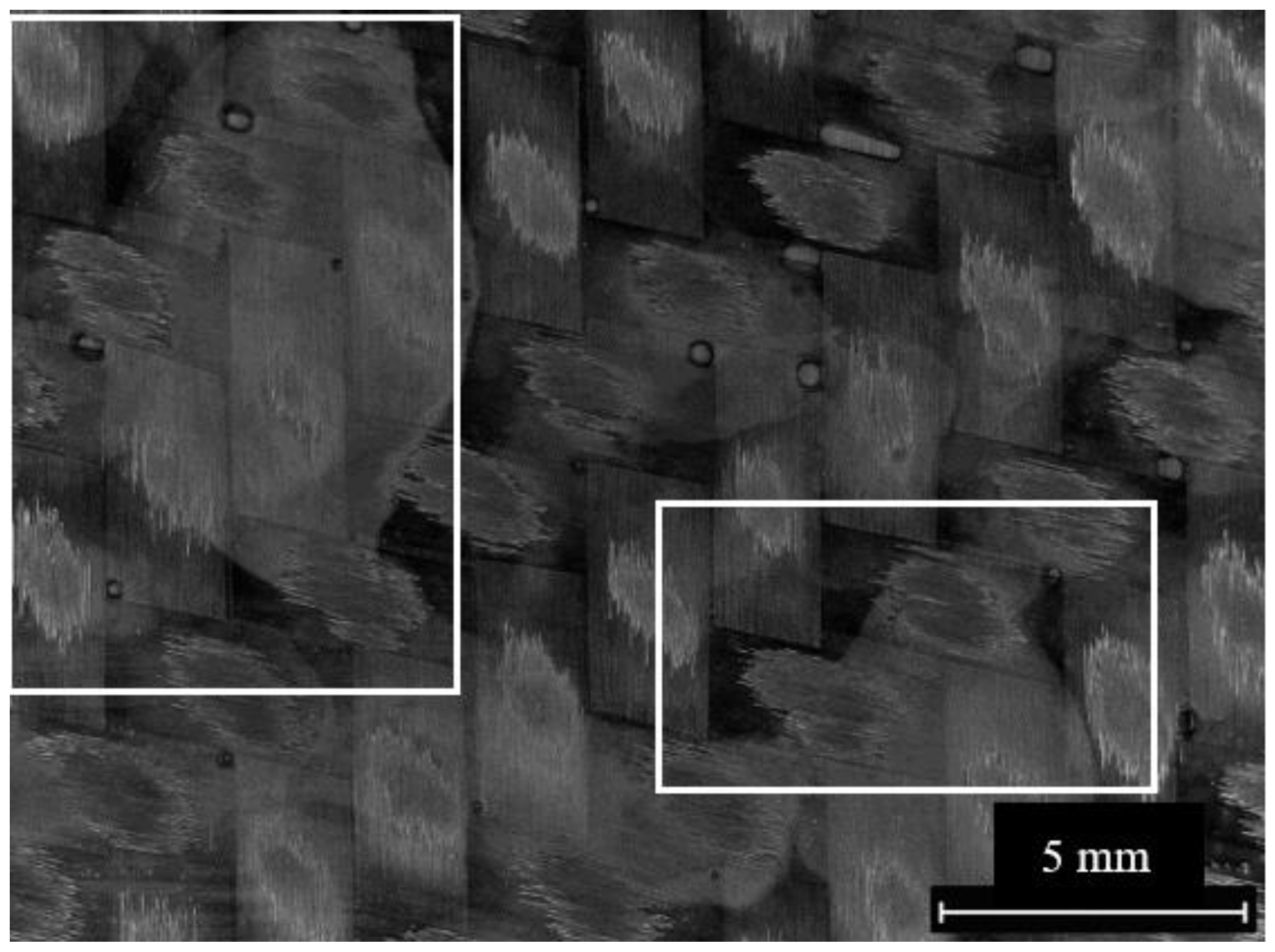
The average gloss before the solar and UVB resistance tests oscillates around 90 GU. From the calculated results, a significant loss of gloss after the sun fastness test of approximately 34% can be observed. After the UVB test, the gloss decreased to an average value of approx. 11.6 GU, i.e., a loss of gloss of approximately 87%. The appearance of the outer surface of the laminate after the UVB test is presented in Figure 7. Localised dulling, in the form of small matte patches, can be seen on the test samples (marked with a white box in the figures). Gloss measurements showed that, in addition to the visible tarnishes, the overall gloss was also reduced.

Figure 7.
Structure of the sample after the sunlight resistance test; magnification 20×.
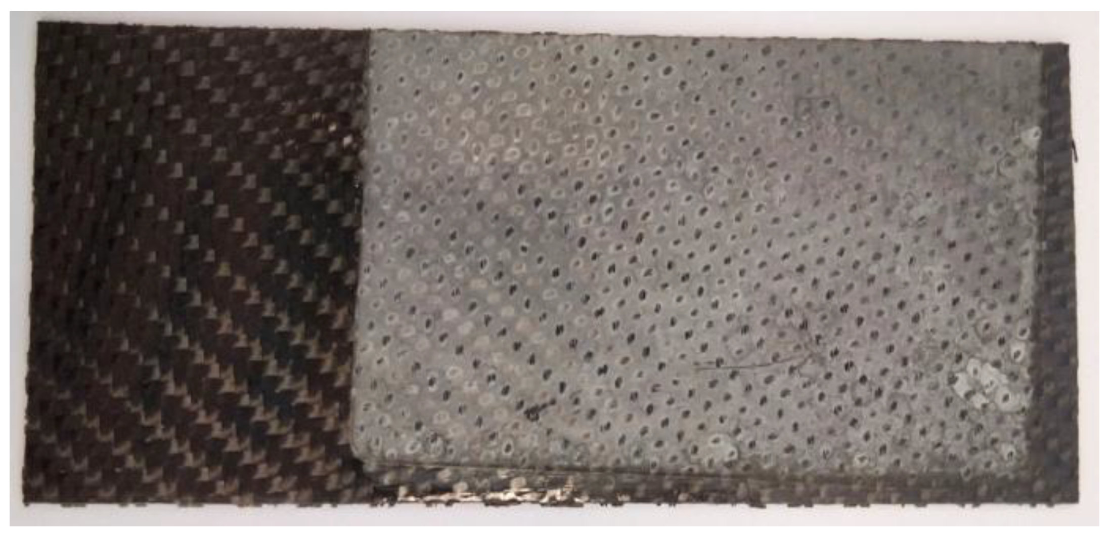
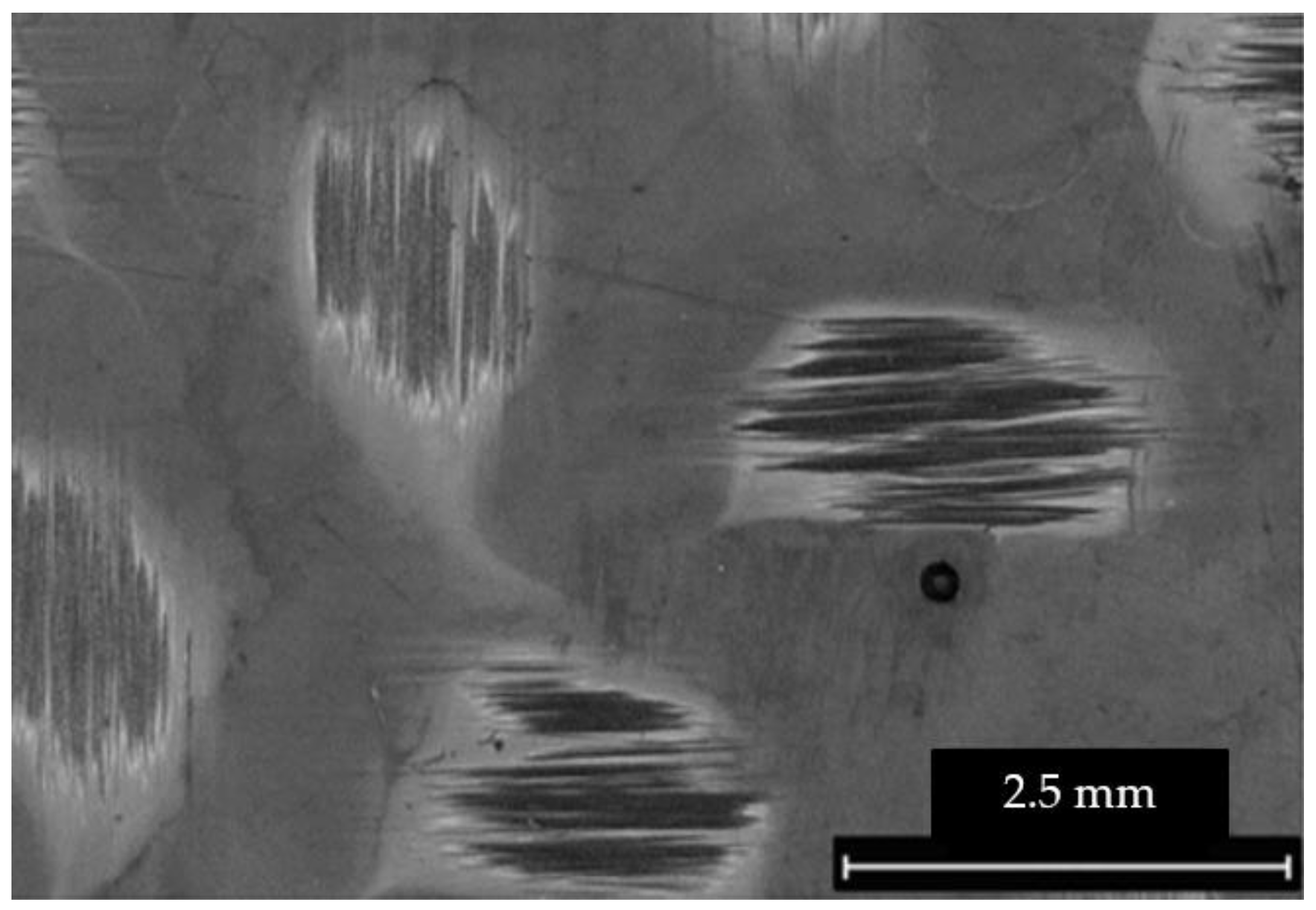
The appearance of the structure after the UVB light resistance test is presented in Figure 8. In addition, the colour change according to the grey scale was determined. The colour change according to the grey scale for all the samples tested was 1/2. The clear tarnishing of the samples over the entire area under magnification is shown in Figure 9.
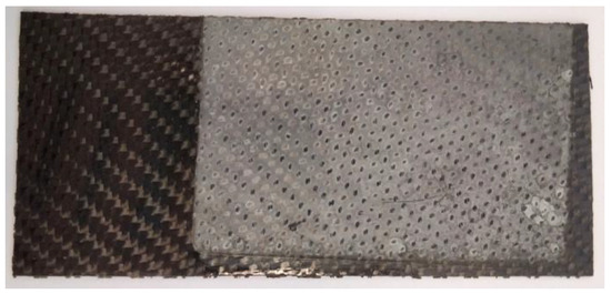
Figure 8.
Example of sample after UVB resistance test.

Figure 9.
Structure of the sample after the UV resistance test; magnification 50×.
Hardness measurements by the ball-and-socket method on the tested three-ply laminate were carried out only on samples after sunlight ageing. The results showed that, despite visible changes in the surface of the composite, the structure itself had strengthened and hardened (Table 5). The hardness (H) compared to the unaged sample increased by about 38 N/mm2, i.e., by about 25%.
Table 5.
Results of hardness measurements by ball method for three-ply laminate before and after ageing.
The specimens after both ageing tests were additionally subjected to static tensile and bending tests according to method-specific test procedures. The static tensile test results for the three-ply laminate before and after the ageing tests are shown in Table 6.
Table 6.
Tensile test results for three-ply laminate before and after ageing tests.
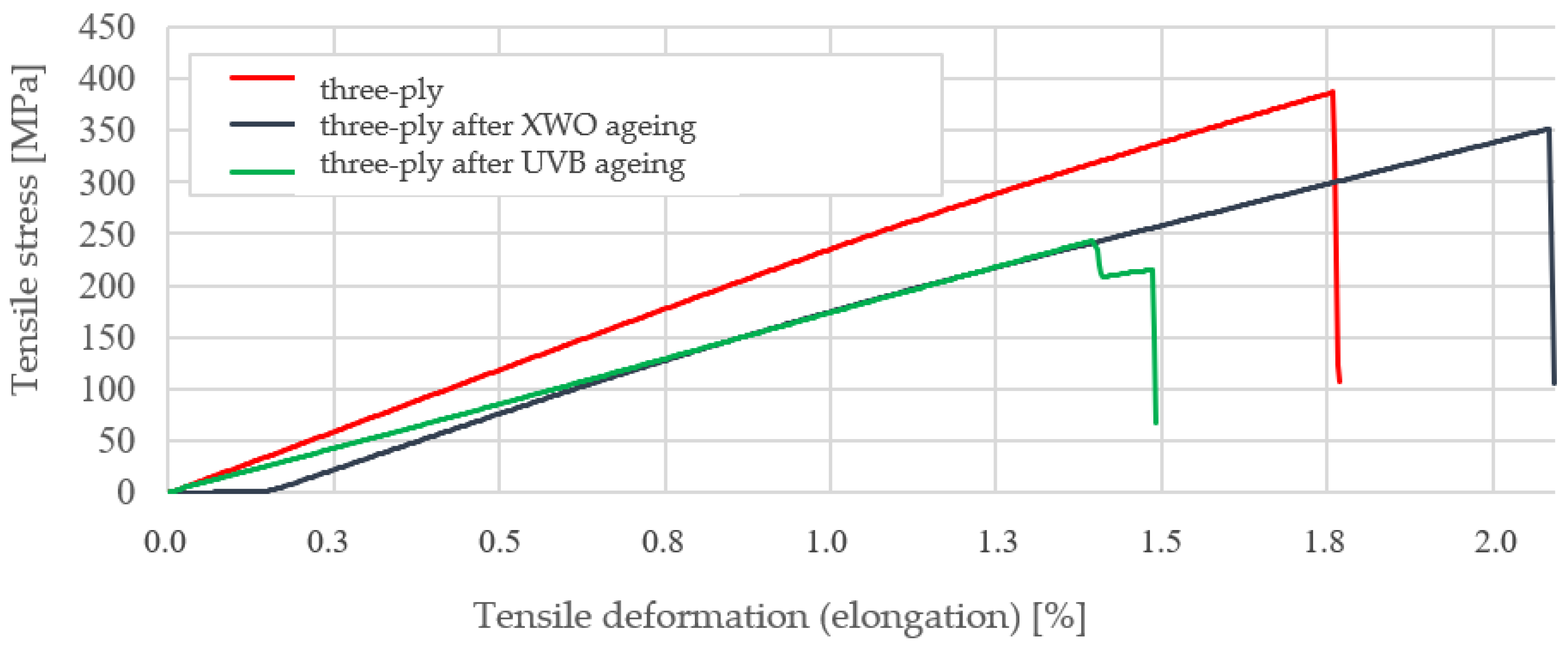
The average tensile stress value for the three-layer sheet is 358.28 ± 19.7 MPa. After the solar resistance ageing test, this value increased by approximately 4% (to a value of 371.4 ± 31.7 MPa) compared to the sample before ageing. After the UVB light resistance test, the value decreased by approximately 29% relative to the unaged three-ply laminate specimens. Figure 10 shows examples of static tensile test plots for an example specimen from each series. The sample whose graph was closest to the average values obtained was selected.
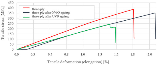
Figure 10.
Examples of stress–strain curves obtained during static tensile testing of a three-ply laminate before and after ageing tests.
The static bending test results for the three-ply laminate before and after ageing tests are summarised in Table 7.
Table 7.
Three-point bending test results for three-ply laminate before and after ageing tests.
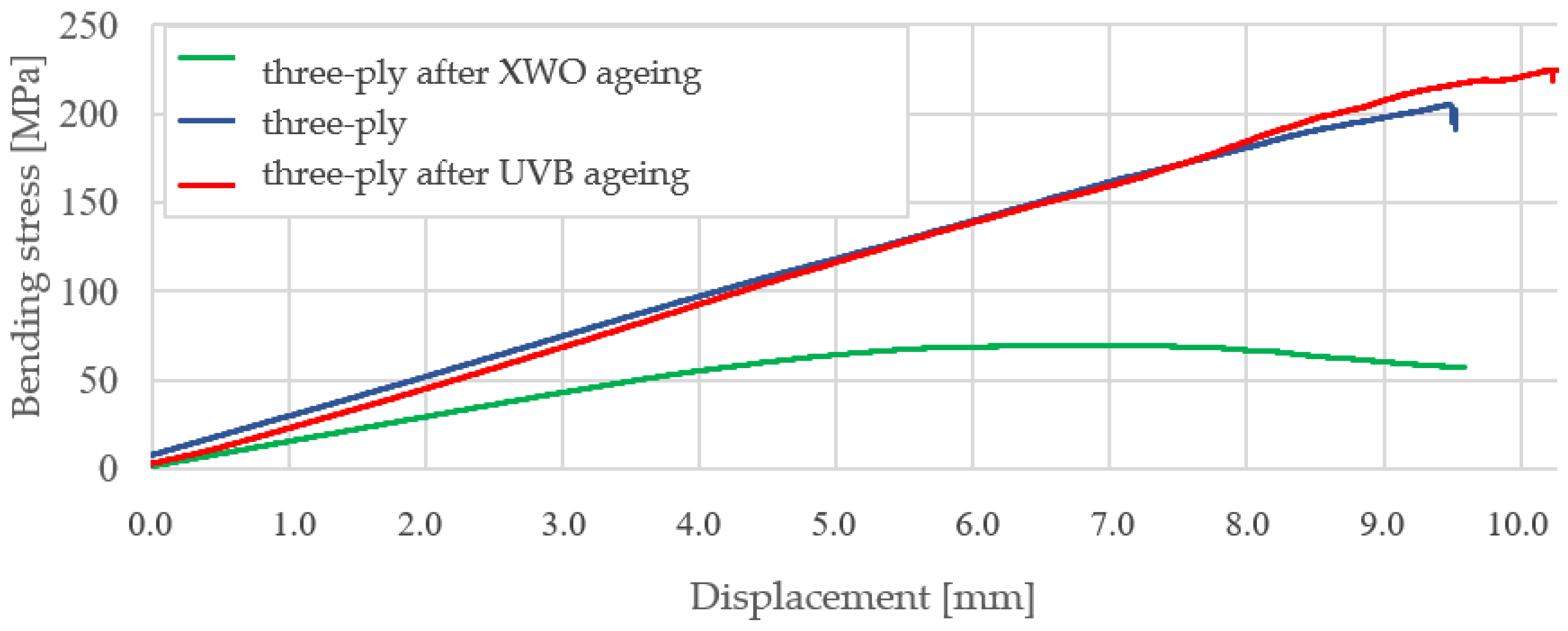
The average bending stress for the three-layer sheet is 204.8 ± 19.7 MPa. After the sunlight resistance ageing test, this value increased by approximately 23% to a value of 251.0 ± 0.7 MPa. After the UVB light resistance test, this value decreased by approximately 69% to a value of 68.60 ± 5.37 Pa relative to the samples without ageing. Figure 11 shows examples of static bending test plots for an example specimen from each series. The sample whose graph was closest to the mean values obtained was selected.
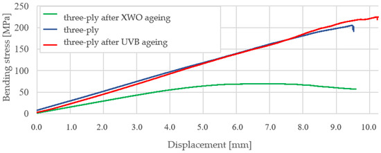
Figure 11.
Examples of stress–displacement plots obtained during static bending tests for three-ply laminate before and after ageing tests.
5.2. Staining Resistance Test—Friction Resistance of Staining
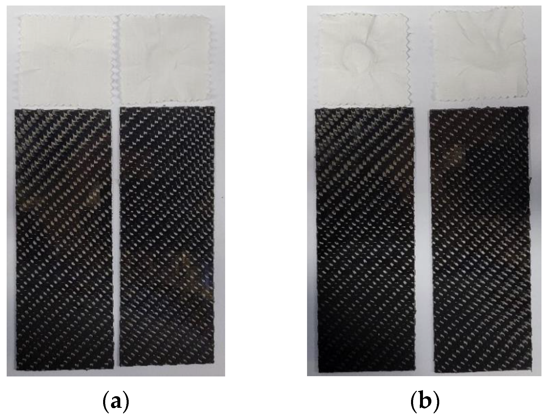
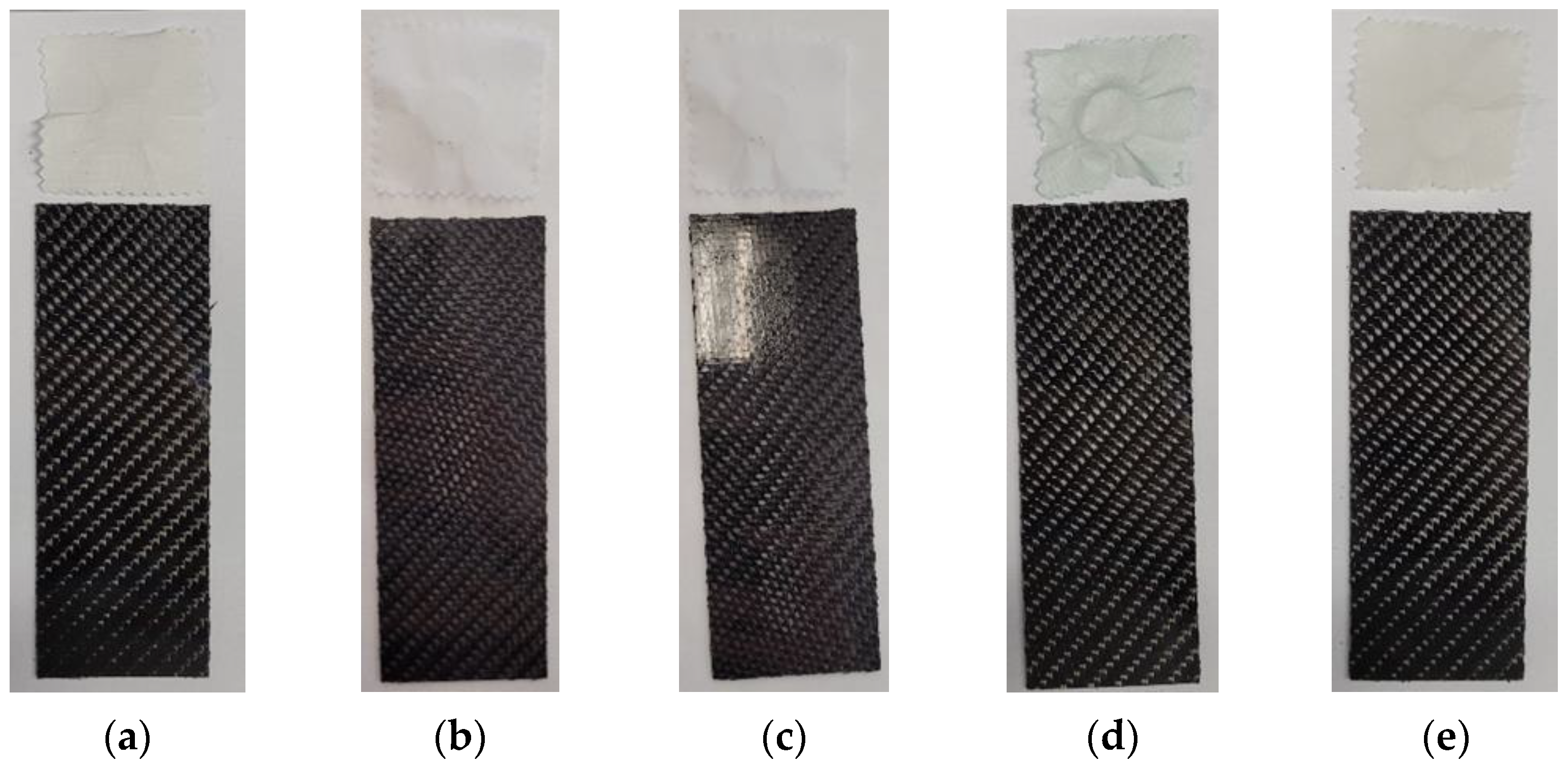
Figure 12 and Figure 13 present the appearance of the specimens together with the rubbing. The fabricated samples show practically no change under rubbing. Only on the sample rubbed with battery acid (Figure 13c) can a slight tarnishing of the rubbed surface be observed. It can be concluded that the composites made of the tested materials have a high resistance to rubbing and to chemicals that may meet them during regular use.
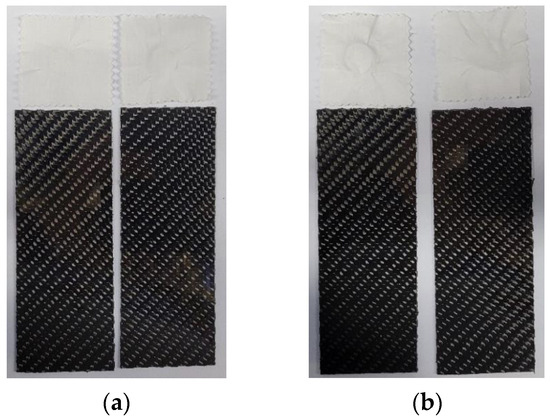
Figure 12.
Samples with the cloth after the rubbing test: (a) dry; (b) wet.
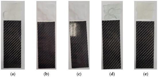
Figure 13.
Samples with the cloth after the rubbing test with (a) brake cleaner; (b) brake fluid; (c) battery acid; (d) G48 coolant; and (e) transmission fluid.
5.3. Effects of Immersion in Water
The results obtained for samples immersed at 23 ± 2 °C and at 70 ± 2 °C are presented in Table 8. By analysing the obtained results, the average mass change after immersion of the samples at 23 ± 2 °C increases by 9.763 ± 1.92%, while after immersion at 70 ± 2 °C it increases by about 3.5% less, i.e., 6.347 ± 1.52%.
Table 8.
Results of weight change of samples after immersion in water.
It can be concluded from the measurements that the tested composite absorbs less water at elevated temperatures. Drying the tested samples for 2 h at 50 °C proves that the composite gets rid of absorbed water quite quickly, and the change in weight of the tested samples decreases in relation to the weight before drying by 78% for samples immersed at 23 ± 2 °C and by 90% for samples immersed at 70 ± 2 °C.
6. Conclusions
Preliminary tests were performed for all reinforcement layer configurations. From the density test, it was found that the number of reinforcement layers did not directly affect the density of the finished composite or the absorbency of the used fabric. The material was evenly saturated with the resin/hardener mixture for all test runs. The use of reinforcement increases the hardness of the composite in the test case by about 17% relative to the pure matrix, regardless of the number of layers used. With the addition of another layer of reinforcement to the two-ply composite, the following increases appeared: the average impact strength (by about 20% between successive configurations), the average bending stress (when increasing the number of reinforcement layers by 50% and 33%, respectively), and the value of Young’s modulus (by about 35% between successive configurations). The average tensile stress value increases by approximately 37% with the addition of a third layer of reinforcement. On the other hand, there is not much difference between the three-layer and four-layer configurations in the values of the determined stress obtained. In view of the above, specific tests were carried out for the three-layer sheets, which had the best strength-to-density ratio. Based on these tests, it was found that the weight of the samples increased by an average of about 8 percent after immersion in water. After drying, the samples quickly give up the absorbed water.
Ageing tests, determining the material’s resistance to six months of use in a temperate environment, showed that the strength properties increase under exposure to sunlight. For example, the average bending stress increased by about 23% and the average tensile stress by about 4%. UVB radiation, on the other hand, causes a strong degradation of the matrix and a significant reduction in the strength properties of the composite (average bending stress decreased by about 69% and average tensile stress decreased by about 29% relative to unaged samples).
The multilayer composite material developed in this work can be successfully used for the skin of a racing car. It is an excellent alternative to the current commercially used materials of this type. Appropriate selection of components and determination of their share in the finished composite allow virtually unlimited possibilities for shaping its resultant properties. The research carried out in this study is a valuable basis for further considerations in the search for new material solutions characterised by the assumed set of functional properties.
Author Contributions
Methodology, M.S.; Validation, M.S.; Formal analysis, M.S.; Investigation, E.K. and M.S. All authors have read and agreed to the published version of the manuscript.
Funding
This research received no external funding.
Institutional Review Board Statement
Not applicable.
Informed Consent Statement
Not applicable.
Data Availability Statement
The data that support the findings of this study are available from the corresponding author upon reasonable request. The data are not publicly available due to privacy.
Conflicts of Interest
The authors declare no conflict of interest.
References
- Yi, X.-S.; Du, S.; Zhang, L. Composite Materials Engineering, Volume 1 Fundamentals of Composite Materials, 1st ed.; Chemical Industry Press, Springer: Berlin/Heidelberg, Germany, 2018. [Google Scholar]
- Elmarakbi, A. Advanced Composite Materials for Automotive Applications: Structural Integrity and Crashworthiness; John Wiley & Sons: Hoboken, NJ, USA, 2013. [Google Scholar]
- Ghassemieh, E. Materials in automotive application, state of the art and prospects. New Trends Dev. Automot. Ind. 2011, 20, 365–394. [Google Scholar]
- Jacob, G.C.; Fellers, J.F.; Simunovic, S.; Starbuck, J.M. Energy Absorption in Polymer Composites for Automotive Crashworthiness. J. Compos. Mater. 2002, 36, 813–850. [Google Scholar] [CrossRef]
- Cheng, F.; Zheng, C.; Liu, Y.; Zuo, W.; Wang, X.; Guo, G. Lightweight Design of CFRP-Laminated Structures by Combining Microscopical Homogenization and Macroscopical Optimization. Int. J. Automot. Technol. 2021, 22, 1427–1436. [Google Scholar] [CrossRef]
- Choi, S.; Hong, S.; Park, S.; Jeong, S. Effects of Diameter-to-thickness Ratio on Impact Energy Absorption Capability of CFRP Cylindrical Crash Box. Int. J. Automot. Technol. 2022, 23, 1663–1671. [Google Scholar] [CrossRef]
- Im, K.-H.; Cha, C.-S.; Kim, S.-K.; Yang, I.-Y. Effects of temperature on impact damages in CFRP composite laminates. Compos. Part B Eng. 2001, 32, 669–682. [Google Scholar] [CrossRef]
- Uthaman, A.; Xian, G.; Thomas, S.; Wang, Y.; Zheng, Q.; Liu, X. Durability of an Epoxy Resin and Its Carbon Fiber- Reinforced Polymer Composite upon Immersion in Water, Acidic, and Alkaline Solutions. Polymers 2020, 12, 614. [Google Scholar] [CrossRef] [PubMed]
- Alessi, S.; Pitarresi, G.; Spadaro, G. Effect of hydrothermal ageing on the thermal and delamination fracture behaviour of CFRP composites. Compos. Part B Eng. 2014, 67, 145–153. [Google Scholar] [CrossRef]
- Perez, J.L.M.; Hodzic, A.; Ayvar, S.; Merson, E. The Influence of Heat During Short Ageing Periods on the Mechanical Properties of CFRP Composites. In Proceedings of the ECCM16—16 the European Conference on Composite Materials, Seville, Spain, 22–26 June 2014; Available online: https://eprints.whiterose.ac.uk/79567/?fbclid=IwAR3wm9a2neaBtIdKJScS-uUv3YpbPERhgZVEP_M4ZPDgqYYg6QdkNw0RO8c (accessed on 23 August 2023).
- Adeniran, O.; Cong, W.; Bediako, E.; Adu, S.P. Environmental affected mechanical performance of additively manufactured carbon fiber–reinforced plastic composites. J. Compos. Mater. 2022, 56, 1139–1150. [Google Scholar] [CrossRef]
- Korkees, F.; Morris, E.; Jarrett, W.; Swart, R. Characterization of moisture absorption and flexural performance of functionalized graphene modified carbon fiber composites under low energy impact. Polym. Compos. 2023, 44, 3325–3340. [Google Scholar] [CrossRef]
- Shi, J.; Bao, L.; Kemmochi, K. Low-velocity impact response and compression after impact assessment of recycled carbon fiber-reinforced polymer composites for future applications. Polym. Compos. 2014, 35, 1494–1506. [Google Scholar] [CrossRef]
- Qiang, X.; Wang, K.; Jiang, X.; Xiao, Y.; E, Y. Effect of Fireproof Coatings on the Post-Fire Behavior of CFRP Composite Sheets. Appl. Sci. 2023, 13, 10369. [Google Scholar] [CrossRef]
- PN EN ISO 2039-1:2004; Plastics—Determination of Hardness—Part 1: Ball Indentation Method. Polish Committee for Standardization: Warsaw, Poland, 2013.
- ISO 527-1:2019; Plastics—Determination of Tensile Properties—Part 1: General Principles. ISO: Geneva, Switzerland, 2019.
- ISO 527-4:2023; Plastics—Determination of Tensile Properties—Part 4: Test Conditions for Isotropic and Orthotropic Fibre-Reinforced Plastic Composites. ISO: Geneva, Switzerland, 2023.
- ISO 14125:1998/Amd 1:2011; Fibre-Reinforced Plastic Composites—Determination of Flexural Properties. Edition 1. ISO: Geneva, Switzerland, 2011.
- PN-EN ISO 178:2019-06; Plastics—Determination of Bending Properties. Polish Committee for Standardization: Warsaw, Poland, 2019.
- ISO 105-X12:2016; Textiles—Tests for Colour Fastness. Part X12: Colour Fastness to Rubbing. ISO: Geneva, Switzerland, 2016.
- DIN EN ISO 4892-2:2013-06; Plastics—Methods of Exposure to Laboratory Light Sources—Part 2: Xenon-arc Lamps. DIN: Berlin, Germany, 2013.
- PN-EN ISO 4892-3:2016-04; Plastics—Methods of exposure to Laboratory Light Sources—Part 3: Fluorescent UV Lamps. Polish Committee for Standardization: Warsaw, Poland, 2016.
- EN ISO 2813:2014; Paints and Varnishes—Determination of Gloss Value at 20°, 60° and 85°. Comite Europeen de Normalisation: Brussels, Belgium, 2014.
- ISO 175:2010; Plastics Methods of Test for the Determination of the Effects of Immersion in Liquid Chemicals. ISO: Geneva, Switzerland, 2010.


Disclaimer/Publisher’s Note: The statements, opinions and data contained in all publications are solely those of the individual author(s) and contributor(s) and not of MDPI and/or the editor(s). MDPI and/or the editor(s) disclaim responsibility for any injury to people or property resulting from any ideas, methods, instructions or products referred to in the content. |
© 2024 by the authors. Licensee MDPI, Basel, Switzerland. This article is an open access article distributed under the terms and conditions of the Creative Commons Attribution (CC BY) license (https://creativecommons.org/licenses/by/4.0/).