
Vibration Reduction on Circular Disks with Vibroacoustic Metamaterials

Abstract
:1. Introduction
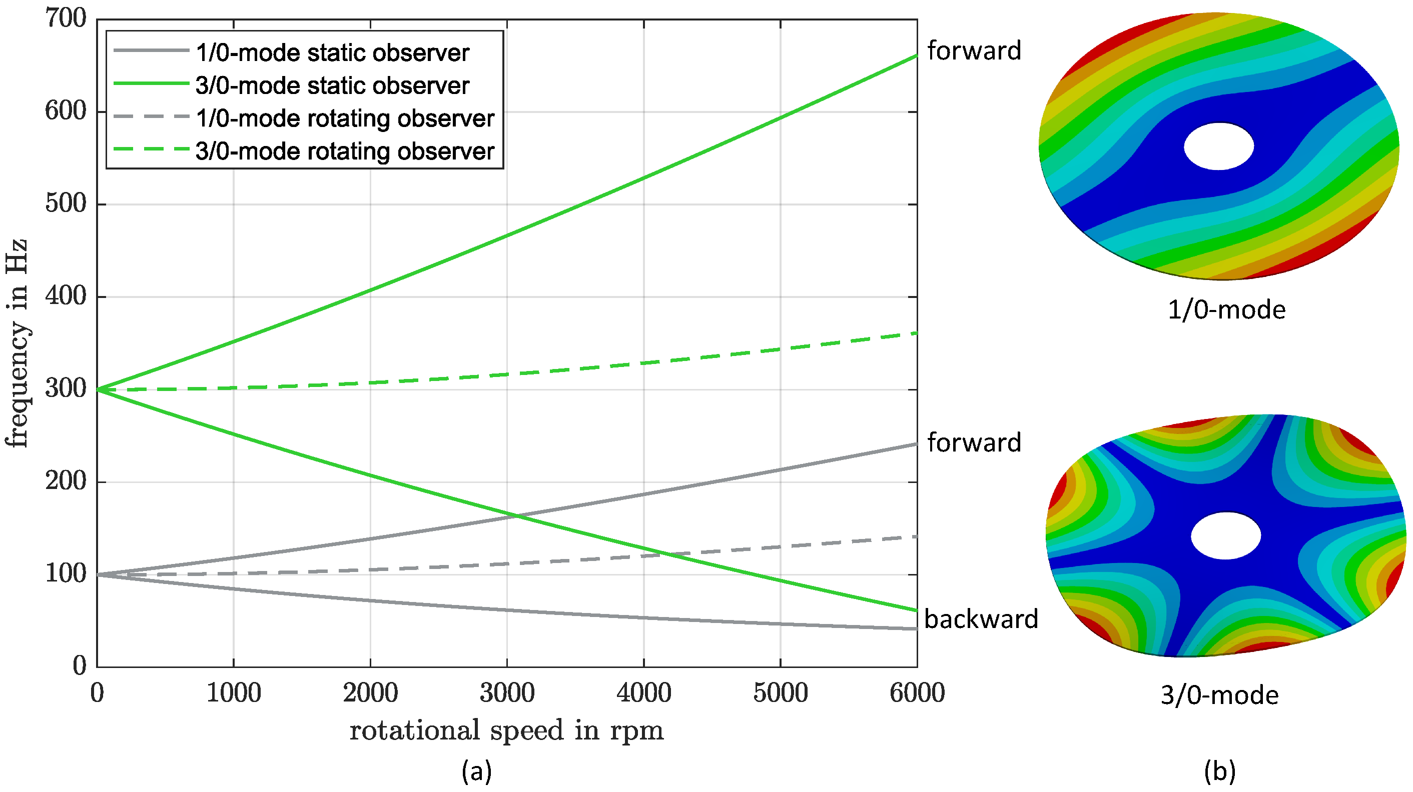
1.1. Vibrations of Rotating Disks
1.1.1. Rotating Observer
1.1.2. Non-Rotating Observer
2. Numerical Design of the Circular Disk with a Vibroacoustic Metamaterial
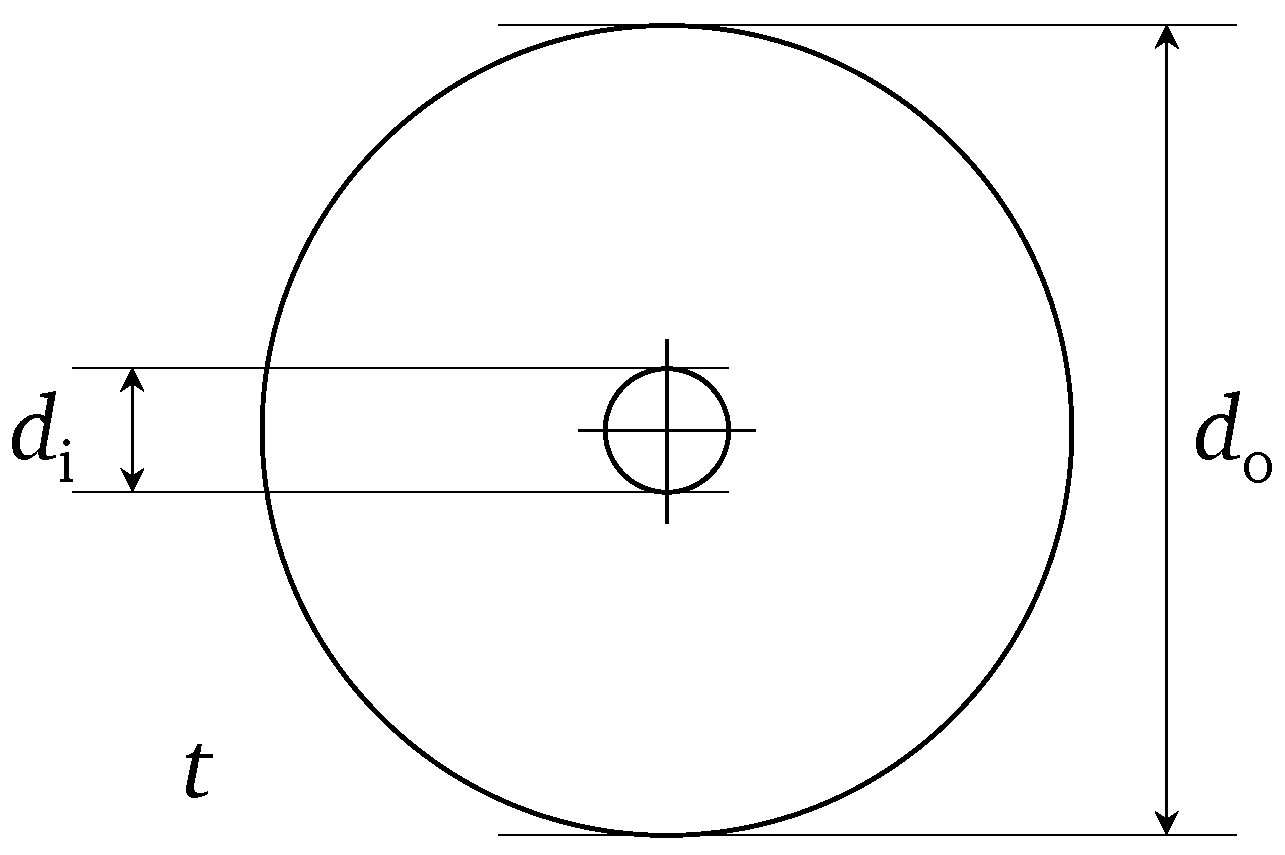
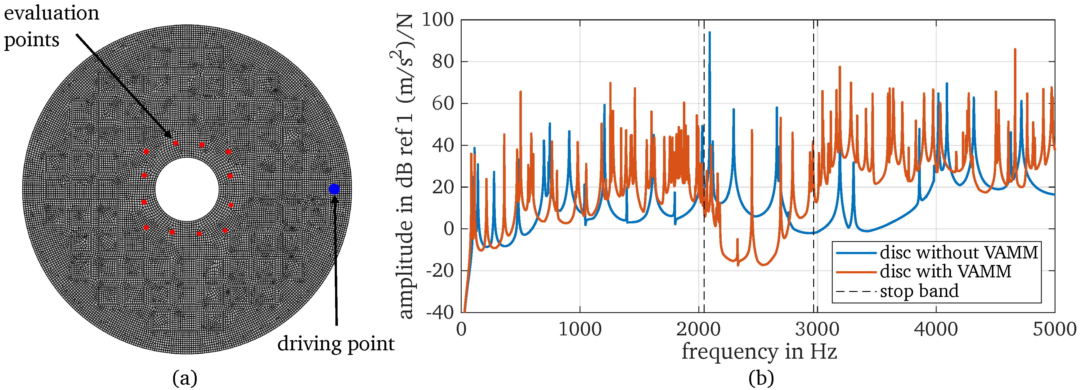
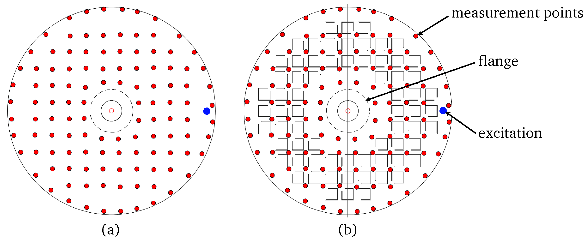
2.1. Numerical Model of the Disk
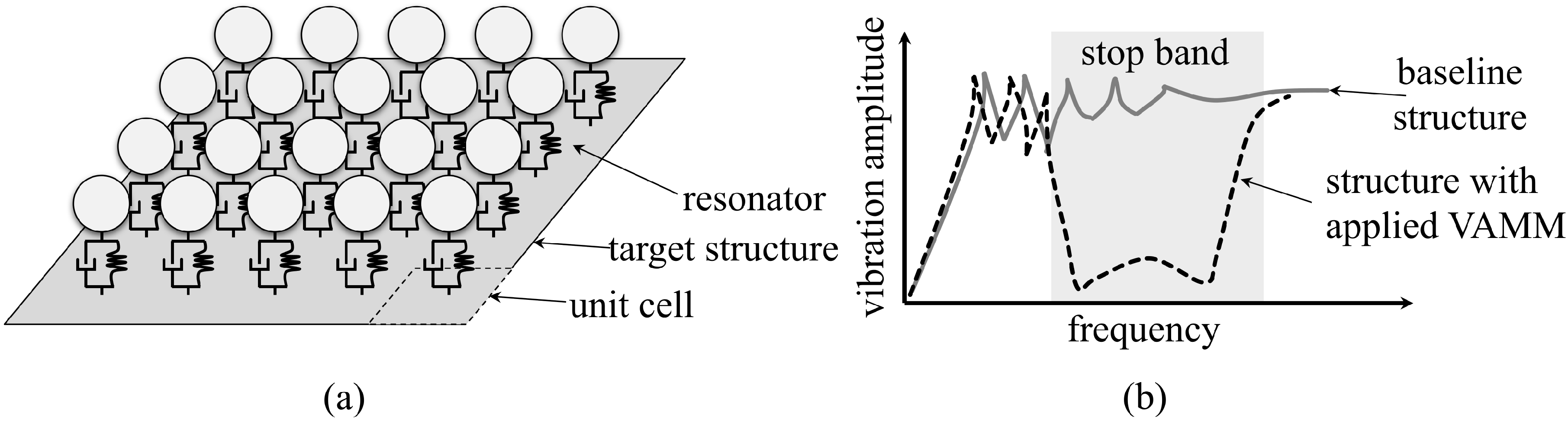
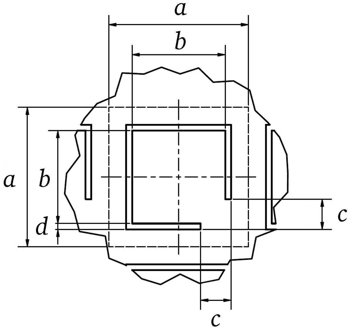
2.2. Numerical Design of the Unit Cell
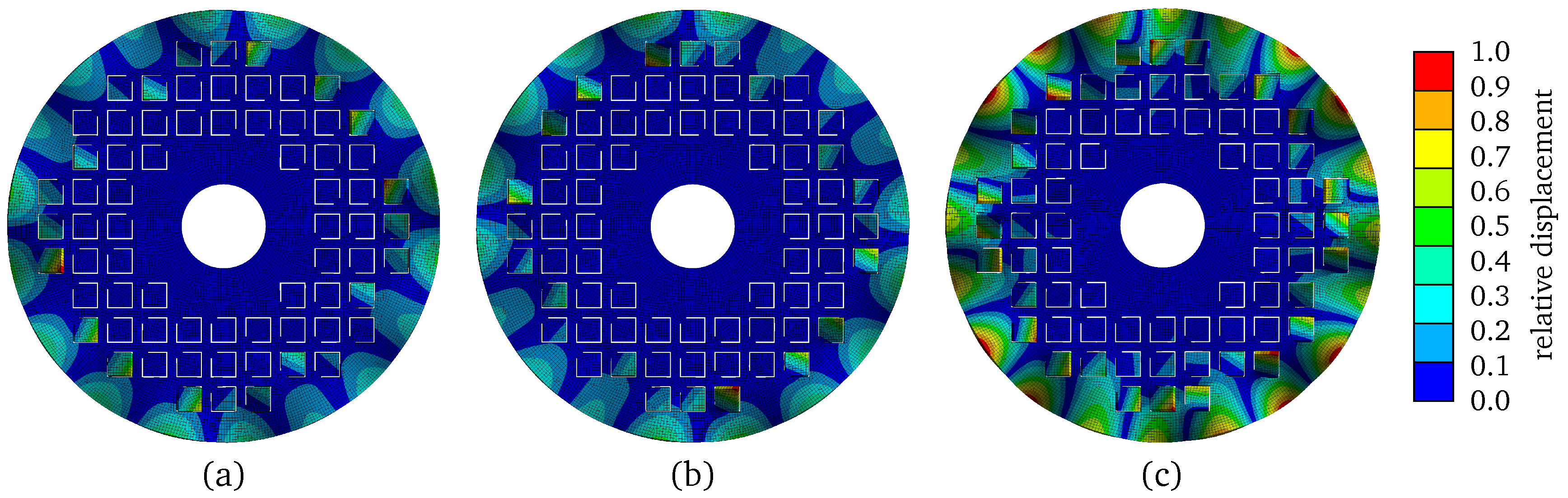
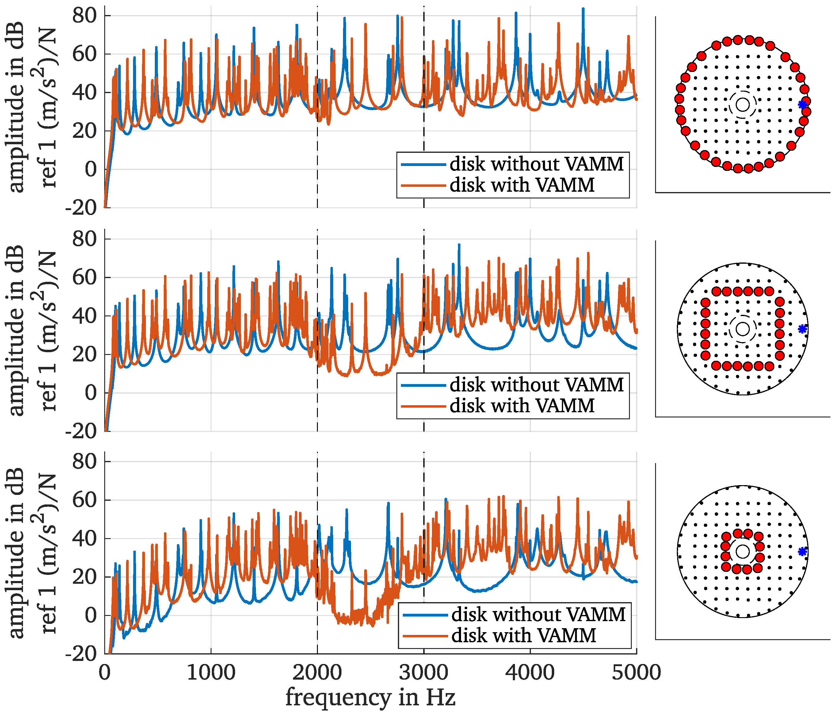
2.3. Numerical Design of Vibroacoustic Metamaterial Compound
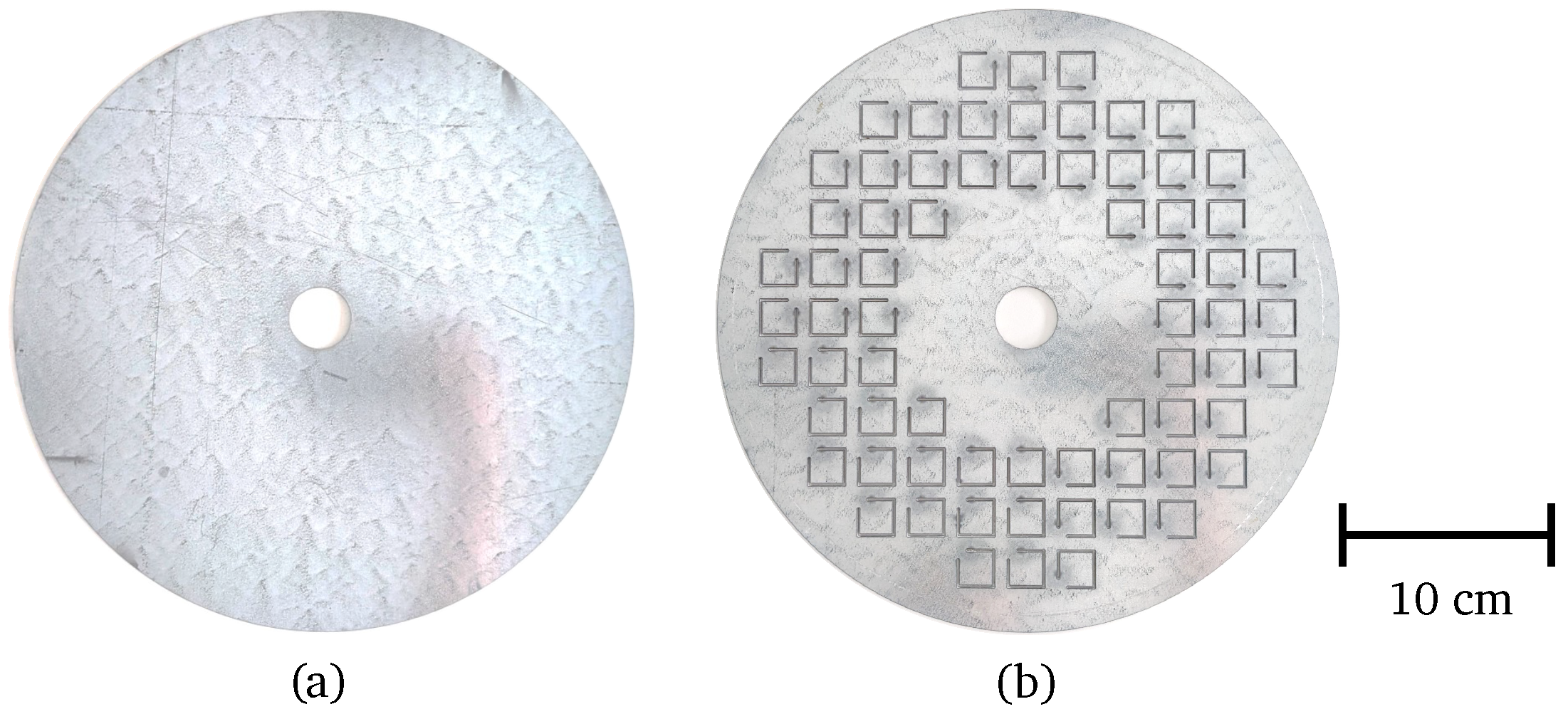
3. Experimental Characterization
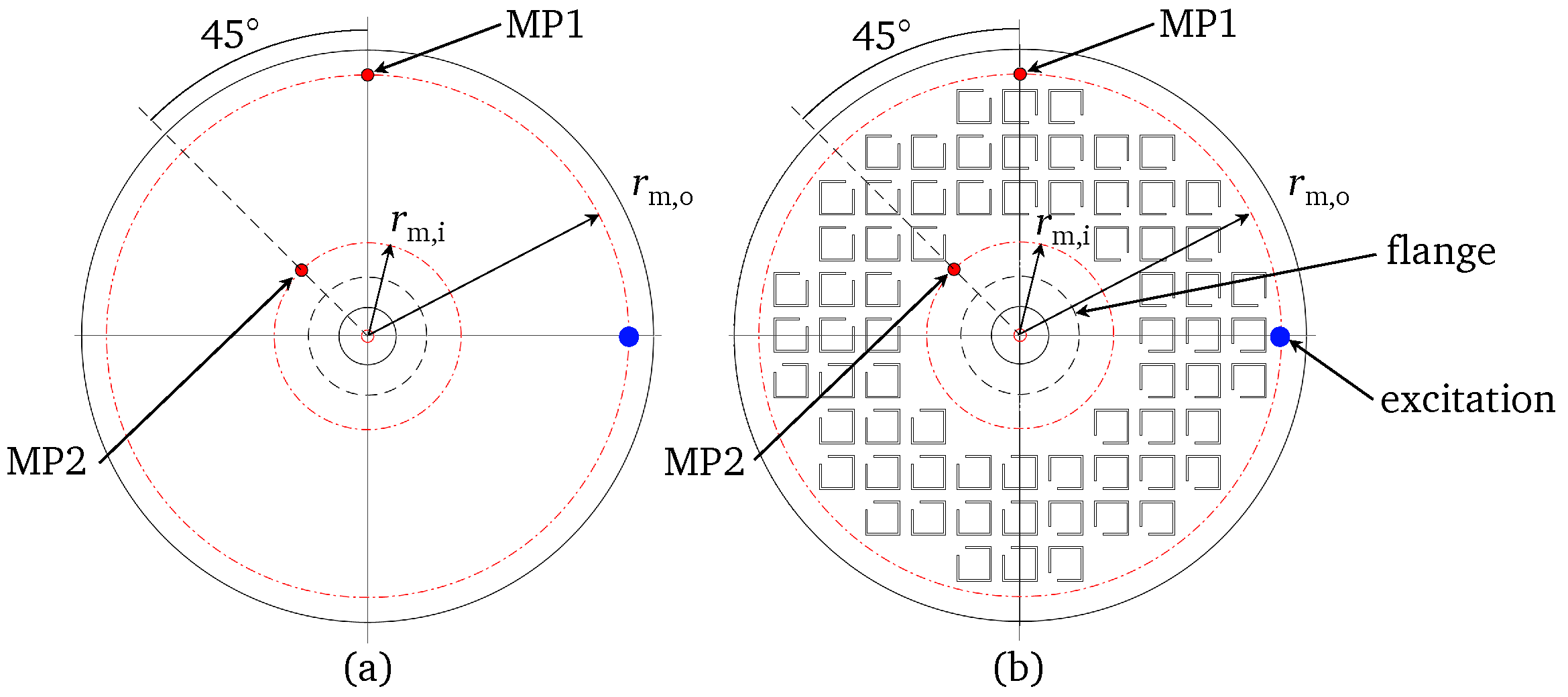
3.1. Measurement Setup
3.2. Non-Rotating State
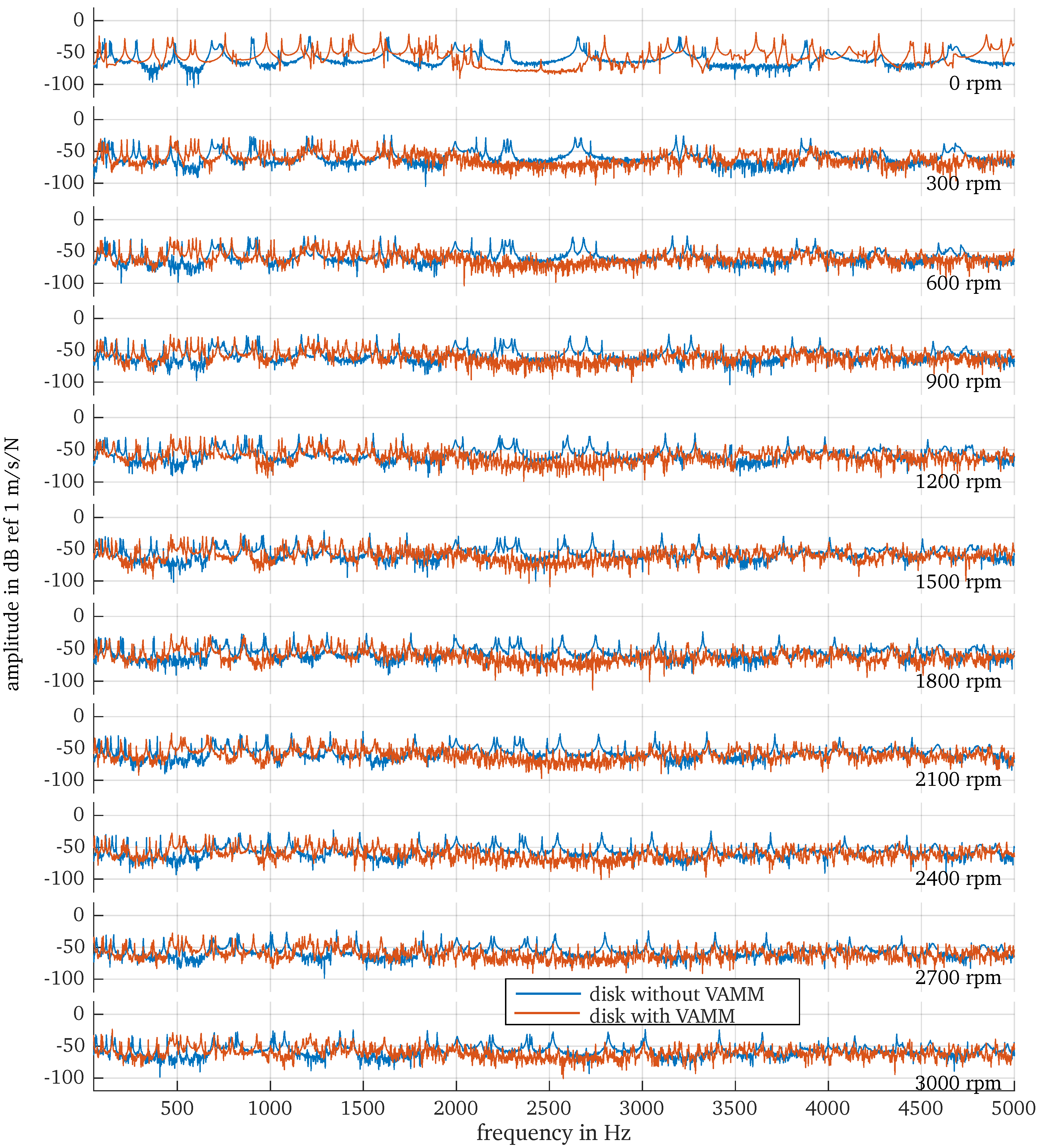
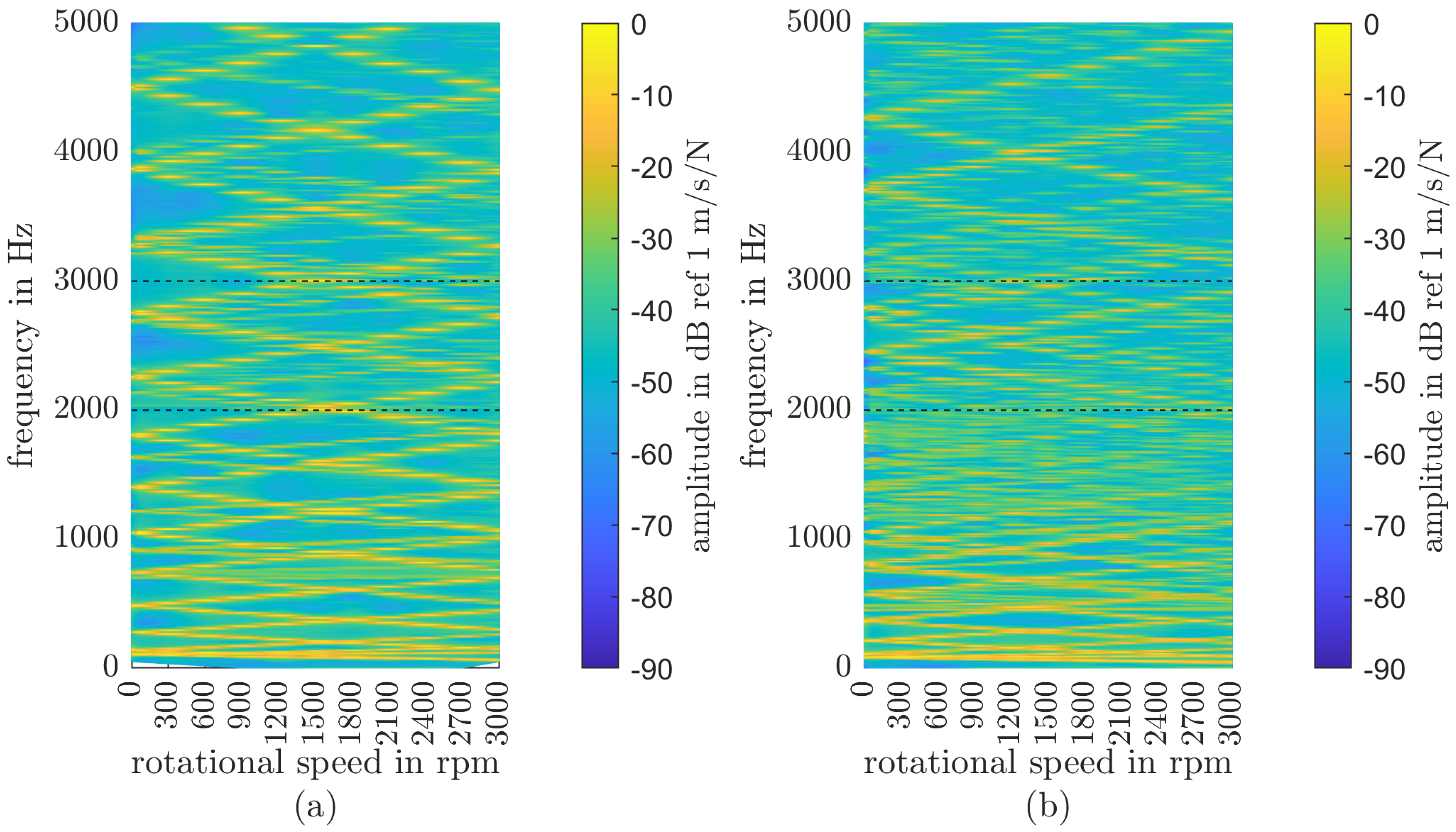
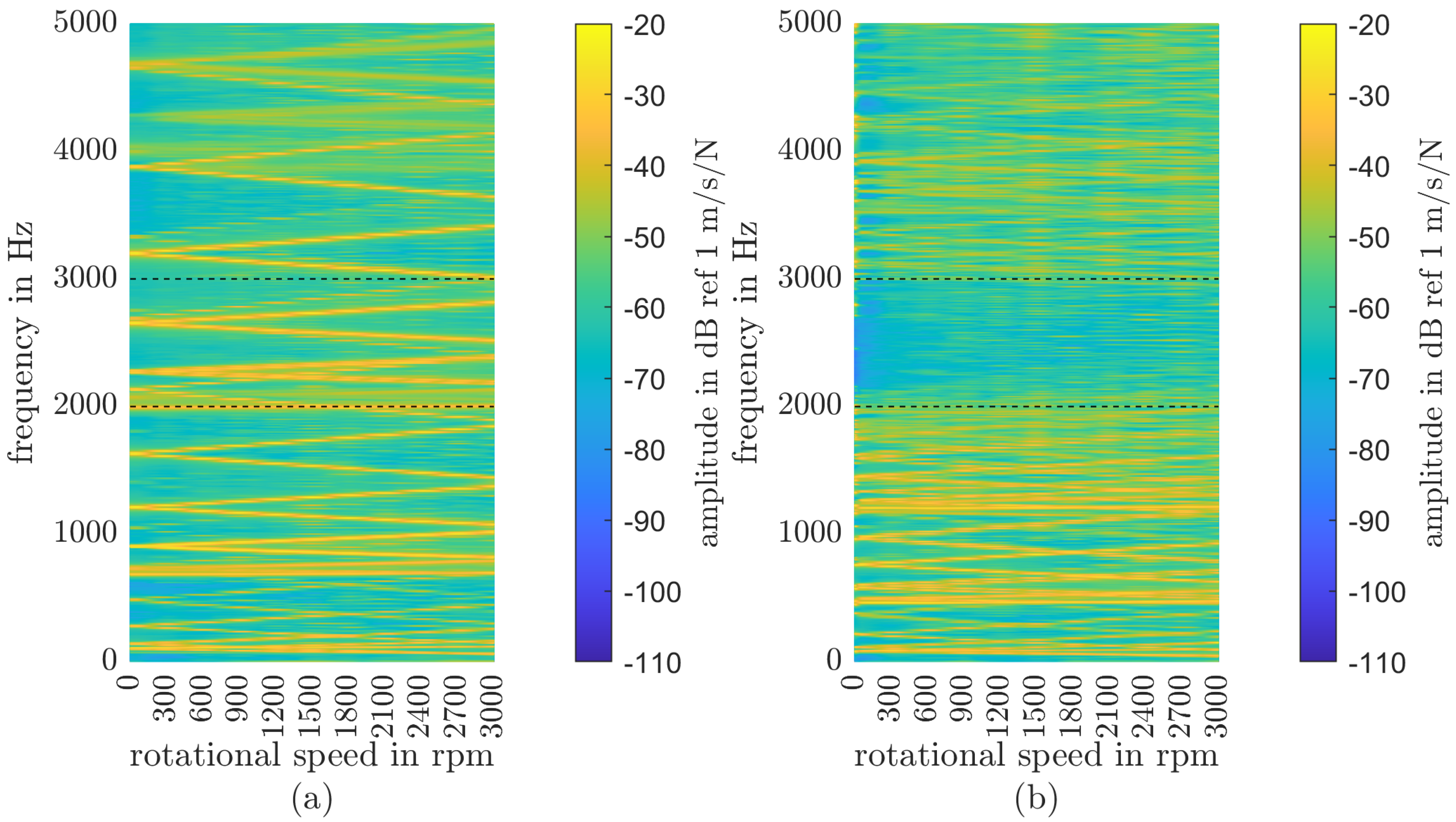
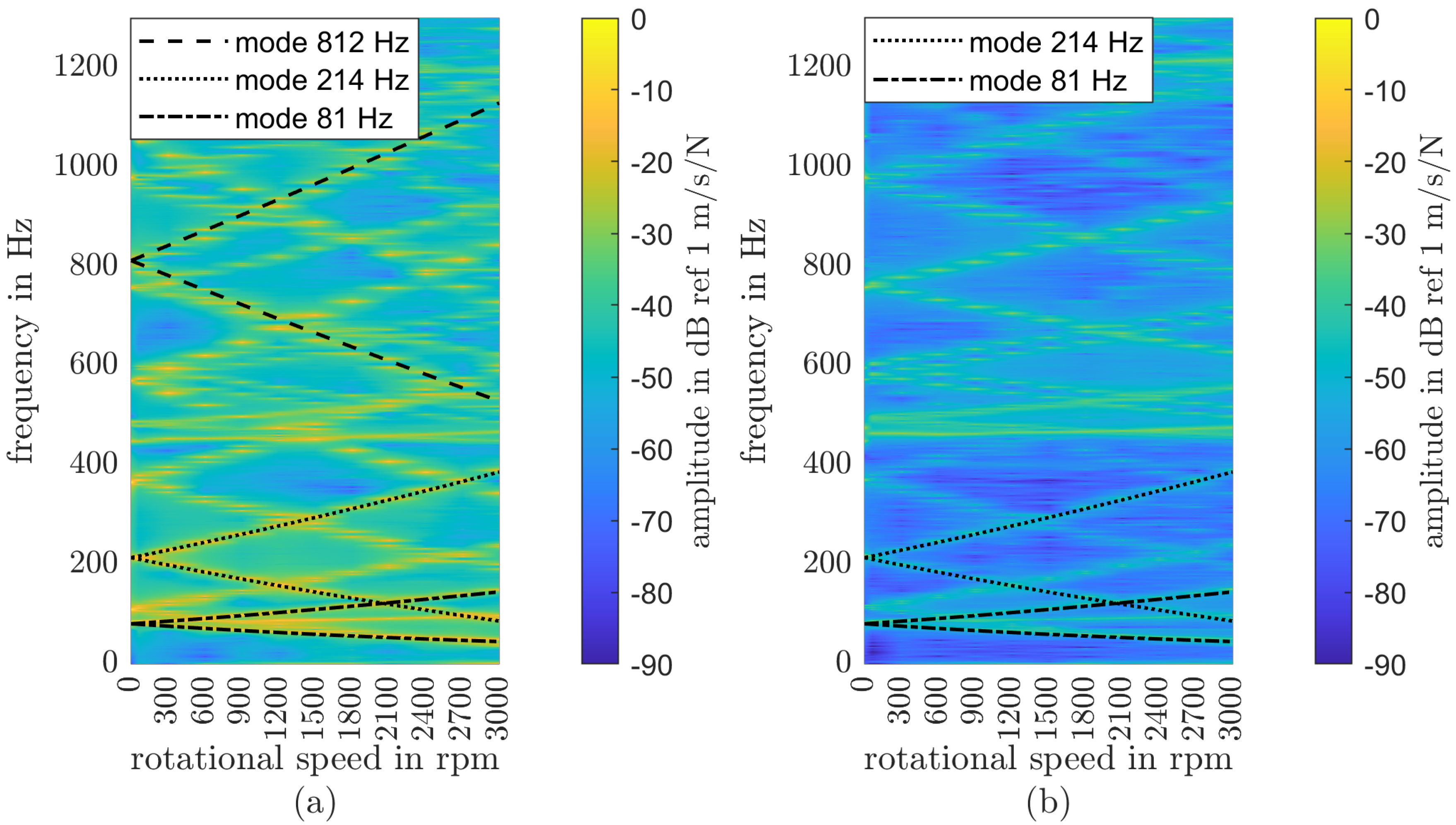
3.3. Rotating State
4. Conclusions
Author Contributions
Funding
Institutional Review Board Statement
Informed Consent Statement
Data Availability Statement
Conflicts of Interest
Abbreviations
| LDV | laser Doppler vibrometer |
| MP | measurement point |
| VAMM | vibroacoustic metamaterial |
Appendix A

References
- Kadic, M.; Milton, G.W.; van Hecke, M.; Wegener, M. 3D metamaterials. Nat. Rev. Phys. 2019, 1, 198–210. [Google Scholar] [CrossRef]
- Veselago, V. The electrodynamics of substances with simultaneously negative values of ε and µ. Sov. Phys. Uspekhi 1968, 10, 509. [Google Scholar] [CrossRef]
- Pendry, J.B.; Holden, A.J.; Stewart, W.J.; Youngs, I. Extremely Low Frequency Plasmons in Metallic Mesostructures. Phys. Rev. Lett. 1996, 76, 4773–4776. [Google Scholar] [CrossRef]
- Pendry, J.; Holden, A.; Robbins, D.; Stewart, W. Magnetism from Conductors, and Enhanced Non-linear Phenomena. Microw. Theory Tech. IEEE Trans. 1999, 47, 2075–2084. [Google Scholar] [CrossRef]
- Liu, Z.; Chan, C.T.; Sheng, P. Analytic model of phononic crystals with local resonances. Phys. Rev. B 2005, 71, 014103. [Google Scholar] [CrossRef]
- Manushyna, D.; Atzrodt, H.; Droste, M.; Deschauer, N. Numerical and conceptual design of vibroacoustic metamaterial solutions for structural vibration reduction in launcher components. In Proceedings of the META 2020, the 11th International Conference on Metamaterials, Photonic Crystals and Plasmonics, Warsaw, Poland, 20–23 July 2020. [Google Scholar]
- Manushyna, D.; Hülsebrock, M.; Kuisl, A.; de Vivo, A.; Heloret, P.; Atzrodt, H.; Rapp, S. Application of vibroacoustic metamaterials for structural vibration reduction in space structures. Mech. Res. Commun. 2023, 129, 104090. [Google Scholar] [CrossRef]
- Rieß, S.; Droste, M.; Atzrodt, H.; López, J.C.; Finger, K.; Erraji, A.; Alasadi, E. Vibroacoustic Metamaterials for Noise and Vibration Reduction on the Cover of Power Electronics of an electric Vehicle. In Proceedings of the 2023 Seventeenth International Congress on Artificial Materials for Novel Wave Phenomena (Metamaterials), Chania, Greece, 11–14 September 2023; pp. X–294–X–296. [Google Scholar] [CrossRef]
- Rieß, S.; Droste, M.; Shariatinia, S.; Atzrodt, H. Design of Vibroacoustic Metamaterial for vibration Reduction on Sheet Metal Structures for Industrial Machinery. In Proceedings of the 16th International Congress on Artificial Materials for Novel 2022 Sixteenth International Congress on Artificial Materials for Novel Wave Phenomena (Metamaterials), Siena, Italy, 12–15 September 2022; pp. X–359–X–361. [Google Scholar] [CrossRef]
- Amaral, D.R.; Ichchou, M.N.; Kołakowski, P.; Fossat, P.; Salvia, M. Lightweight gearbox housing with enhanced vibro-acoustic behavior through the use of locally resonant metamaterials. Appl. Acoust. 2023, 210, 109435. [Google Scholar] [CrossRef]
- Schelle, F.; Janssen, M.; Maue, J. Neuartige lärmgeminderte Sägeblätter für die Holzbearbeitung. In Proceedings of the Fortschritte der Akustik—DAGA 2016—42, Aachen, Germany, 14–17 March 2016; Vorländer, M., Fels, J., Eds.; Deutsche Gesellschaft für Akustik e.V. (DEGA): Berlin, Germany, 2016; pp. 1226–1228. [Google Scholar]
- Rieß, S.; Kaal, W.; Herold, S. Vibration reduction on circular saw blades with vibroacoustic metamaterials. Bull. Pol. Acad. Sci. Tech. Sci. 2023, 71, e147921. [Google Scholar] [CrossRef]
- Yu, D.; Liu, Y.; Wang, G.; Cai, L.; Qiu, J. Low frequency torsional vibration gaps in the shaft with locally resonant structures. Phys. Lett. A 2006, 348, 410–415. [Google Scholar] [CrossRef]
- Li, L.; Chen, T.; Wang, X.P.; Li, B. One-Dimensional Bi-Stage Phononic Band Gap Shaft Structure for Reducing Torsional Vibration. Appl. Mech. Mater. 2011, 141, 54–58. [Google Scholar] [CrossRef]
- Wang, K.; Zhou, J.; Xu, D.; Ouyang, H. Tunable low-frequency torsional-wave band gaps in a meta-shaft. J. Phys. D Appl. Phys. 2019, 52, 055104. [Google Scholar] [CrossRef]
- Richards, D.; Pines, D. Passive reduction of gear mesh vibration using a periodic drive shaft. J. Sound Vib. 2003, 264, 317–342. [Google Scholar] [CrossRef]
- Alsaffar, Y.; Sassi, S.; Baz, A. Band gap characteristics of periodic gyroscopic systems. J. Sound Vib. 2018, 435, 301–322. [Google Scholar] [CrossRef]
- Fan, L.; He, Y.; Chen, X.; Zhao, X. Elastic metamaterial shaft with a stack-like resonator for low-frequency vibration isolation. J. Phys. D Appl. Phys. 2020, 53, 105101. [Google Scholar] [CrossRef]
- Li, L.; Lv, R.; Cai, A.; Xie, M.; Chen, Y.; Huang, G. Low-frequency vibration suppression of a multi-layered elastic metamaterial shaft with discretized scatters. J. Phys. D Appl. Phys. 2019, 52, 055105. [Google Scholar] [CrossRef]
- Rosso, C.; Bonisoli, E.; Bruzzone, F. On the Implementation of Metastructures in Rotordynamics. In Rotating Machinery, Vibro-Acoustics & Laser Vibrometry; Conference Proceedings of the Society for Experimental Mechanics Series; Di Maio, D., Ed.; Springer: Cham, Switzerland, 2018; Volume 7, pp. 43–51. [Google Scholar] [CrossRef]
- Jäger, M. Methode zur Modellierung von Vibroakustischen Metamaterialien in Rotierenden Systemen am Beispiel Eines Kreissägeblatts. Master’s Thesis, Technische Hochschule Mittelhessen, Gießen, Germany, 2023. [Google Scholar]
- Ahn, T.K.; Mote, C. Mode identification of a rotating disk. Exp. Mech. 1998, 38, 250–254. [Google Scholar] [CrossRef]
- Mehdigholi, H. Forced Vibration of Rotating Discs and Interaction with Non-Rotating Structures. Ph.D. Thesis, Imperial College, London, UK, 1991. [Google Scholar]
- Southwell, R.V. On the Free Transverse Vibrations of a Uniform Circular Disc Clamped at Its Centre; and on the Effects of Rotation. Proc. R. Soc. London. Ser. A Contain. Pap. A Math. Phys. Character 1922, 101, 133–153. [Google Scholar] [CrossRef]
- Birenbaum, C. Beitrag zur Rechnerischen und Experimentellen Auslegung von Kreissäge-Stammblättern für die Holzbearbeitung; University of Stuttgart, DISS: Stuttgart, Germany, 2013. [Google Scholar]
- Presas, A.; Valentin, D.; Valero, C.; Egusquiza, M.; Egusquiza, E. Experimental Measurements of the Natural Frequencies and Mode Shapes of Rotating Disk-Blades-Disk Assemblies from the Stationary Frame. Appl. Sci. 2019, 9, 3864. [Google Scholar] [CrossRef]
- Lich, J.; Wollmann, T.; Filippatos, A.; Gude, M.; Czarske, J.; Kuschmierz, R. Spatially Resolved Experimental Modal Analysis on High-Speed Composite Rotors Using a Non-Contact, Non-Rotating Sensor. Sensors 2021, 21, 4705. [Google Scholar] [CrossRef]
- Weiland, S.; Birenbaum, C. Optimization of geometric features of circular saw blades and parameters of the manufacturing process aided by optiSLang. Weimar.-Optim.-Und Stochastiktage 2014, 11, 1–21. [Google Scholar]
- Rieß, S.; Droste, M.; Kaal, W.; Atzrodt, H. Lärmreduktion an Kreissägeblättern mit vibroakustischen Metamaterialien. Lärmbekämpfung 2023, 18, 27–31. [Google Scholar] [CrossRef]
- Riess, S.; Droste, M.; Atzrodt, H. Noise Reduction of circular Saw Blades using Vibroacoustic Metamaterial. In Proceedings of the 2022 Sixteenth International Congress on Artificial Materials for Novel Wave Phenomena (Metamaterials), Siena, Italy, 12–17 September 2022; IEEE: Piscataway, NJ, USA, 2022; pp. X–362–X–364. [Google Scholar] [CrossRef]
- Maue, J.H. Lärmschutz-Arbeitsblatt IFA-LSA 02-375— Geräuschgeminderte Diamant-Trennscheiben für Steinsägen—Konstruktiver Aufbau der Trennscheiben und Lärmminderungserfolge; Deutsche Gesetzliche Unfallversicherung e.V. (DGUV): Berlin, Germany, 2015. [Google Scholar]
- Pahlitzsch, G.; Rowinski, B. Über das Schwingungsverhalten von Kreissägeblättern - Erste Mitteilung: Bestimmung und Auswirkungen der geometrischen Form und des Vorspannungszustandes der Sägeblätter. Holz Als Roh-Und Werkst. 1966, 24, 125–134. [Google Scholar] [CrossRef]
- Bloch, F. Über die Quantenmechanik der Elektronen in Kristallgittern. Z. Für Phys. 1929, 52, 555–600. [Google Scholar] [CrossRef]
- Schmidt, R. Experimenteller Nachweis zur Reduktion von Schwingungen bei Rotierenden Kreissägeblättern Durch den Einsatz von Vibroakustischen Metamaterialen. Master’s Thesis, Hochschule Darmstadt, Darmstadt, Germany, 2023. [Google Scholar]
- Kuttner, T.; Rohnen, A. Praxis der Schwingungsmessung: Messtechnik und Schwingungsanalyse mit MATLAB®; Springer: Wiesbaden, Germany, 2019; pp. 325–329. [Google Scholar] [CrossRef]


| Number | 1 | 2 | 3 | |
|---|---|---|---|---|
| Mode Shape |  | 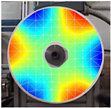 | 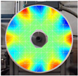 | |
| Frequency | 81 Hz | 214 Hz | 812 Hz | |
| Nodal Diameters | 1 | 3 | 6 | |
| MP1 | Frequency forward (3) | 145 Hz | 386 Hz | 1129 Hz |
| Frequency backward (3) | 45 Hz | 86 Hz | 529 Hz | |
| Nodal Diameters | 1 | 3 | 0 | |
| MP2 | Frequency forward (3) | 145 Hz | 386 Hz | - |
| Frequency backward (3) | 45 Hz | 86 Hz | - |
Disclaimer/Publisher’s Note: The statements, opinions and data contained in all publications are solely those of the individual author(s) and contributor(s) and not of MDPI and/or the editor(s). MDPI and/or the editor(s) disclaim responsibility for any injury to people or property resulting from any ideas, methods, instructions or products referred to in the content. |
© 2024 by the authors. Licensee MDPI, Basel, Switzerland. This article is an open access article distributed under the terms and conditions of the Creative Commons Attribution (CC BY) license (https://creativecommons.org/licenses/by/4.0/).
Share and Cite
Rieß, S.; Schmidt, R.; Kaal, W.; Atzrodt, H.; Herold, S. Vibration Reduction on Circular Disks with Vibroacoustic Metamaterials. Appl. Sci. 2024, 14, 4637. https://doi.org/10.3390/app14114637
Rieß S, Schmidt R, Kaal W, Atzrodt H, Herold S. Vibration Reduction on Circular Disks with Vibroacoustic Metamaterials. Applied Sciences. 2024; 14(11):4637. https://doi.org/10.3390/app14114637
Chicago/Turabian StyleRieß, Sebastian, Ron Schmidt, William Kaal, Heiko Atzrodt, and Sven Herold. 2024. "Vibration Reduction on Circular Disks with Vibroacoustic Metamaterials" Applied Sciences 14, no. 11: 4637. https://doi.org/10.3390/app14114637