
Optimizing the Shape of the Spinning Electrode for Needleless Coaxial Electrospinning

Abstract
:1. Introduction
2. Design and Simulations
2.1. Mathematical Model of the Original Design
2.2. Mathematical Model of the Optimized Design
3. Experiments
3.1. Materials and Equipment
3.2. Methods
4. Discussion
5. Conclusions
Author Contributions
Funding
Institutional Review Board Statement
Informed Consent Statement
Data Availability Statement
Acknowledgments
Conflicts of Interest
References
- Kidoaki, S.; Kwon, I.K.; Matsuda, T. Mesoscopic Spatial Designs of Nano- and Microfiber Meshes for Tissue-Engineering Matrix and Scaffold Based on Newly Devised Multilayering and Mixing Electrospinning Techniques. Biomaterials 2005, 26, 37–46. [Google Scholar] [CrossRef] [PubMed]
- Lannutti, J.; Reneker, D.; Ma, T.; Tomasko, D.; Farson, D. Electrospinning for Tissue Engineering Scaffolds. Mater. Sci. Eng. C 2007, 27, 504–509. [Google Scholar] [CrossRef]
- Sundarrajan, S.; Tan, K.L.; Lim, S.H.; Ramakrishna, S. Electrospun Nanofibers for Air Filtration Applications. Procedia Eng. 2014, 75, 159–163. [Google Scholar] [CrossRef]
- Maria Leena, M.; Vimala Bharathi, S.K.; Moses, J.A.; Anandharamakrishnan, C. 11—Potential Applications of Nanofibers in Beverage Industry. In Nanoengineering in the Beverage Industry; Grumezescu, A.M., Holban, A.M., Eds.; Academic Press: Cambridge, MA, USA, 2020; pp. 333–368. ISBN 978-0-12-816677-2. [Google Scholar]
- Mironov, V.; Visconti, R.P.; Kasyanov, V.; Forgacs, G.; Drake, C.J.; Markwald, R.R. Organ Printing: Tissue Spheroids as Building Blocks. Biomaterials 2009, 30, 2164–2174. [Google Scholar] [CrossRef]
- Liu, H.; Bai, Y.; Huang, C.; Wang, Y.; Ji, Y.; Du, Y.; Xu, L.; Yu, D.-G.; Bligh, S.W.A. Recent Progress of Electrospun Herbal Medicine Nanofibers. Biomolecules 2023, 13, 184. [Google Scholar] [CrossRef] [PubMed]
- Horev, Y.D.; Maity, A.; Zheng, Y.; Milyutin, Y.; Khatib, M.; Yuan, M.; Suckeveriene, R.Y.; Tang, N.; Wu, W.; Haick, H. Stretchable and Highly Permeable Nanofibrous Sensors for Detecting Complex Human Body Motion. Adv. Mater. 2021, 33, 2102488. [Google Scholar] [CrossRef] [PubMed]
- Han, W.; Wang, Y.; Su, J.; Xin, X.; Guo, Y.; Long, Y.-Z.; Ramakrishna, S. Fabrication of Nanofibrous Sensors by Electrospinning. Sci. China Technol. Sci. 2019, 62, 886–894. [Google Scholar] [CrossRef]
- Liu, Q.; Ramakrishna, S.; Long, Y.-Z. Electrospun Flexible Sensor. J. Semicond. 2019, 40, 111603. [Google Scholar] [CrossRef]
- Wang, D.; Wang, L.; Shen, G. Nanofiber/Nanowires-Based Flexible and Stretchable Sensors. J. Semicond. 2020, 41, 041605. [Google Scholar] [CrossRef]
- Ning, C.; Xiang, S.; Sun, X.; Zhao, X.; Wei, C.; Li, L.; Zheng, G.; Dong, K. Highly Stretchable Kirigami-Patterned Nanofiber-Based Nanogenerators for Harvesting Human Motion Energy to Power Wearable Electronics. Mater. Futures 2024, 3, 025101. [Google Scholar] [CrossRef]
- Skrivanek, J.; Jirkovec, R.; Batka, O.; Holec, P.; Kalous, T.; Zabka, P.; Bilek, M.; Pokorny, P. Production of Modified Composite Nanofiber Yarns with Functional Particles. ACS Omega 2023, 8, 1114–1120. [Google Scholar] [CrossRef]
- Doshi, J.; Reneker, D.H. Electrospinning Process and Applications of Electrospun Fibers. J. Electrost. 1995, 35, 151–160. [Google Scholar] [CrossRef]
- Ellison, C.J.; Phatak, A.; Giles, D.W.; Macosko, C.W.; Bates, F.S. Melt Blown Nanofibers: Fiber Diameter Distributions and Onset of Fiber Breakup. Polymer 2007, 48, 3306–3316. [Google Scholar] [CrossRef]
- Sarkar, K.; Gomez, C.; Zambrano, S.; Ramirez, M.; de Hoyos, E.; Vasquez, H.; Lozano, K. Electrospinning to ForcespinningTM. Mater. Today 2010, 13, 12–14. [Google Scholar] [CrossRef]
- Skrivanek, J.; Holec, P.; Batka, O.; Bilek, M.; Pokorny, P. Optimization of the Spinneret Rotation Speed and Airflow Parameters for the Nozzleless Forcespinning of a Polymer Solution. Polymers 2022, 14, 1042. [Google Scholar] [CrossRef]
- Harfenist, S.A.; Cambron, S.D.; Nelson, E.W.; Berry, S.M.; Isham, A.W.; Crain, M.M.; Walsh, K.M.; Keynton, R.S.; Cohn, R.W. Direct Drawing of Suspended Filamentary Micro- and Nanostructures from Liquid Polymers. Nano Lett. 2004, 4, 1931–1937. [Google Scholar] [CrossRef]
- Reneker, D.H.; Yarin, A.L. Electrospinning Jets and Polymer Nanofibers. Polymer 2008, 49, 2387–2425. [Google Scholar] [CrossRef]
- Ahmadi Bonakdar, M.; Rodrigue, D. Electrospinning: Processes, Structures, and Materials. Macromol 2024, 4, 58–103. [Google Scholar] [CrossRef]
- Kessick, R.; Fenn, J.; Tepper, G. The Use of AC Potentials in Electrospraying and Electrospinning Processes. Polymer 2004, 45, 2981–2984. [Google Scholar] [CrossRef]
- Martinez-Prieto, N.; Ehmann, K.; Cao, J. Near-Field Electrospinning on Nonconductive Substrates Using AC Fields. Procedia CIRP 2020, 93, 120–124. [Google Scholar] [CrossRef]
- Farkas, B.; Balogh, A.; Cselkó, R.; Molnár, K.; Farkas, A.; Borbás, E.; Marosi, G.; Nagy, Z.K. Corona Alternating Current Electrospinning: A Combined Approach for Increasing the Productivity of Electrospinning. Int. J. Pharm. 2019, 561, 219–227. [Google Scholar] [CrossRef] [PubMed]
- Ganchenko, G.; Amiroudine, S.; Bodiguel, H.; Polyanskikh, S.; Demekhin, E. Tonks-Frenkel Instability in Electrolyte under High-Frequency AC Electric Fields. Eur. Phys. J. E 2019, 42, 37. [Google Scholar] [CrossRef] [PubMed]
- Baťka, O.; Beran, J.; Skrivánek, J. Analysis of Electric Field Depending on the Diameter of the Ball Electrode. In Proceedings of the 10th International Conference on Nanomaterials—Research & Application, Brno, Czech Republic, 16–18 October 2019; pp. 230–234. [Google Scholar]
- Bazilevsky, A.V.; Yarin, A.L.; Megaridis, C.M. Co-Electrospinning of Core−Shell Fibers Using a Single-Nozzle Technique. Langmuir 2007, 23, 2311–2314. [Google Scholar] [CrossRef] [PubMed]
- Valtera, J.; Bílek, M.; Vyslouzilova, L.; Komarek, J.; Skrivanek, J.; Soukupova, J.; Zabka, P.; Lukas, D.; Beran, J. Wire Spinner for Coaxial Electrospinning. Nanocon 2015 2015, 7, 14–16. [Google Scholar]


| Ball Diameter [mm] | Electric Field [V/mm] | Emid/Eedge | ||
|---|---|---|---|---|
| Emid | Eedge | Eball | ||
| no ball | 7809 | 8986 | x | 0.869 |
| 10 | 6765 | 7285 | 1652 | 0.929 |
| 20 | 6694 | 7020 | 789 | 0.954 |
| 30 | 6643 | 6793 | 523 | 0.978 |
| 40 | 6601 | 6576 | 385 | 1.004 |
| 50 | 6554 | 6389 | 311 | 1.026 |
| 60 | 6508 | 6168 | 267 | 1.055 |
| Ball Diameter [mm] | Electric Field [V/mm] | Emid/Eedge | ||
|---|---|---|---|---|
| Emid | Eedge | Eball | ||
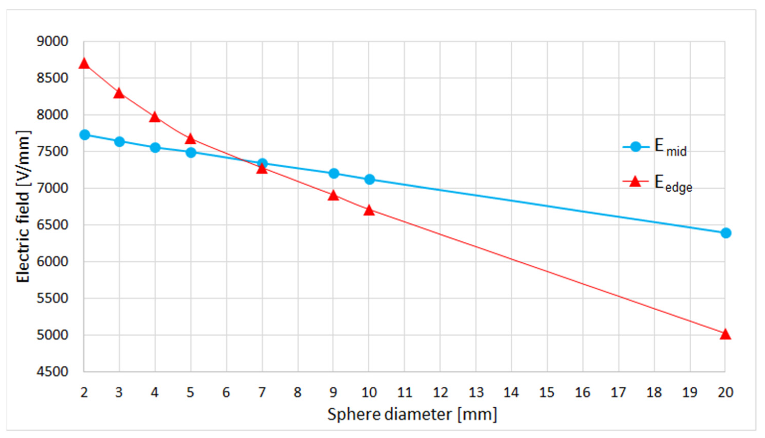
| 1 | 7809 | 8986 | x | 0.869 |
| 2 | 7734 | 8704 | 15,618 | 0.889 |
| 3 | 7647 | 8305 | 12,278 | 0.921 |
| 4 | 7559 | 7975 | 10,315 | 0.948 |
| 5 | 7495 | 7681 | 8558 | 0.976 |
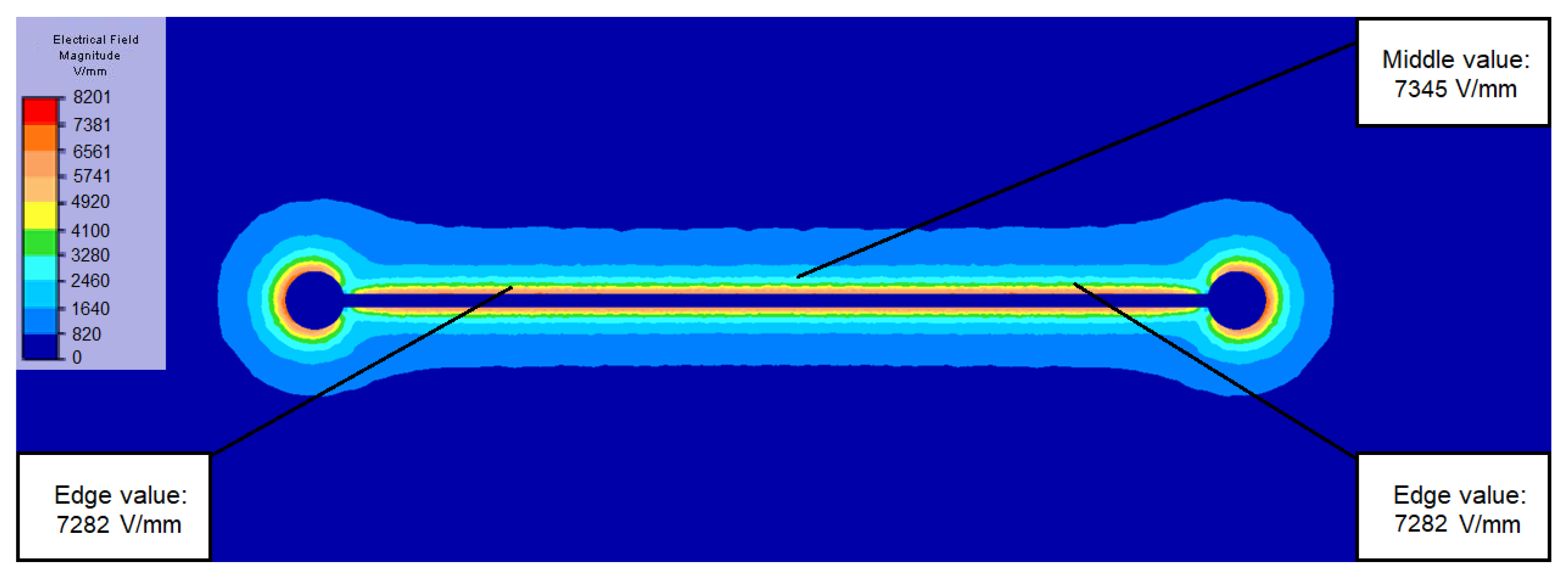
| 7 | 7345 | 7282 | 6296 | 1.009 |
| 9 | 7205 | 6911 | 4897 | 1.043 |
| 10 | 7124 | 6714 | 4600 | 1.061 |
| 20 | 6395 | 5023 | 2596 | 1.273 |
Disclaimer/Publisher’s Note: The statements, opinions and data contained in all publications are solely those of the individual author(s) and contributor(s) and not of MDPI and/or the editor(s). MDPI and/or the editor(s) disclaim responsibility for any injury to people or property resulting from any ideas, methods, instructions or products referred to in the content. |
© 2024 by the authors. Licensee MDPI, Basel, Switzerland. This article is an open access article distributed under the terms and conditions of the Creative Commons Attribution (CC BY) license (https://creativecommons.org/licenses/by/4.0/).
Share and Cite
Batka, O.; Skrivanek, J.; Beran, J. Optimizing the Shape of the Spinning Electrode for Needleless Coaxial Electrospinning. Appl. Sci. 2024, 14, 4638. https://doi.org/10.3390/app14114638
Batka O, Skrivanek J, Beran J. Optimizing the Shape of the Spinning Electrode for Needleless Coaxial Electrospinning. Applied Sciences. 2024; 14(11):4638. https://doi.org/10.3390/app14114638
Chicago/Turabian StyleBatka, Ondrej, Josef Skrivanek, and Jaroslav Beran. 2024. "Optimizing the Shape of the Spinning Electrode for Needleless Coaxial Electrospinning" Applied Sciences 14, no. 11: 4638. https://doi.org/10.3390/app14114638