Article

Production of Transportation Fuels from Fischer–Tropsch Waxes: Distillation, Blending, and Hydrocracking

by
Jakub Frątczak
1,
Joanna Górska
1,
Martin Babor
1,
Zahra Gholami
1,*,
José Miguel Hidalgo Herrador
1 and
Héctor de Paz Carmona
2,*
1
ORLEN UniCRE a.s., Revoluční 1521/84, 400 01 Ústí nad Labem, Czech Republic
2
Chemical Engineering and Pharmaceutical Technology Department, University of La Laguna (ULL), Avda. Astrofísico Fco. Sánchez s/n, 38200 La Laguna, Spain
*
Authors to whom correspondence should be addressed.
Appl. Sci. 2024, 14(11), 4656; https://doi.org/10.3390/app14114656
Submission received: 9 May 2024 / Revised: 24 May 2024 / Accepted: 27 May 2024 / Published: 28 May 2024
(This article belongs to the Special Issue Environmental Catalysis and Green Chemistry)

Abstract

:
Nowadays, transportation fuels such as diesel or gasoline are standardly produced from crude oil refining. These petroleum-based products are gradually replaced by more environmentally friendly sources, such as Fischer–Tropsch diesel fractions and other biofuels. The present work reports the distillation of Fischer–Tropsch (FTS) waxes and its use for fuel production by (i) blending the FTS wax diesel fraction with fossil diesel (7:93; 15:85; 30:70; and 50:50 wt.%) and (ii) blending the FTS wax heavy fraction (360–700 °C) with vacuum gas oil (10–50 wt.%) followed by hydrocracking at industrial operating conditions (T = 420 °C, WHSV = 0.5–1.0 h−1, P = 10.0 MPa). The obtained products in both cases were analysed and compared with standard EN590 for petroleum-diesel fuels. Overall, our results point to the suitability of the distillation of FTS waxes for renewable fuel production, either by straight blending of the diesel petroleum-based products or co-hydrocracking of the heavy fraction with vacuum gas oil.

1. Introduction

The diversification of fuel sources has become a hot topic of widespread interest in contemporary discourse [1,2,3]. Using fossil fuels in transportation stands out as a primary contributor to environmental degradation, marked by the emission of CO2, CO, volatile organic compounds (VOCs), NOx, and SOx [4,5]. Consequently, global atmospheric pollution levels continue to escalate unabated. This impetus for change is further underscored by many factors, including exploring alternative energy sources [6], strategic fuel considerations for nations [7], and the tightening grip of environmental regulations [8,9]. A notable exemplar of this regulatory push is the European Union (EU), which has committed to reducing greenhouse gas (GHG) emissions by 50–55% by 2030 (relative to 1990 levels) and achieving carbon neutrality by 2050 [10,11].
Alternative technologies to directly use crude oil to produce fuels are in development. An important example is XTL technology (Feed to Liquid) [12], which synthesises liquid fuels from carbon sources such as coal (CTL), natural gas (GTL), biomass (BTL), or waste residues (WTL). Thus, fuels can be produced by the Fischer–Tropsch Synthesis (FTS) from the gasification of coal (CTL), biomass (BTL), or waste (WTL) sources, producing synthesis gas (syngas, CO + H2), a raw material to produce FTS hydrocarbons [13,14,15].
On a well-established commercial scale, the well-known FTS process can be carried out under different conditions that determine the distribution of the final hydrocarbons obtained. More than 50% of FTS waxes are produced worldwide through the low-temperature process [16], obtaining FTS crude products, which can be separated by using flash distillation into gases (C1–C4), FTS naphtha (C5–C11), FTS diesel (C9–C22), and FTS heavy waxes (>C20) fractions [17,18]. Further upgrading FTS products is unnecessary when using them as an automotive fuel blending compound. However, depending on the local legislation and engine types, it could not be suitable for straight use as a fuel. The heavy fraction of FTS waxes (>C20) is typically upgraded by fluidised-bed catalytic cracking (FCC) or hydrocracking with further refining to produce naphtha and diesel fuel [17,19]. Another process is straight FTS wax hydrocracking, which could produce 80% of diesel with a relatively high cetane number [16].
The hydrocracking reaction is a refining exothermal catalytic process in which the reaction conditions and catalyst used determine the quality of the final products. This process has already been widely investigated. In this sense, Leckel et al. [20] showed the appropriateness of using sulfided NiMo/SiO2-Al2O3, NiW/SiO2-Al2O3, and a non-sulfidic noble metal catalyst modified with MoO3 (Pt/MoO3/SiO2-Al2O3) for diesel production through the low-pressure hydrocracking process of FTS waxes [17,20,21,22].
Another interesting point of view for upgrading FTS waxes is their co-processing with fossil crude oil fractions [23]. Vacuum gas oil (VGO) can be a good candidate for the hydrocracking reaction in co-processing with FTS waxes having similar boiling range fractions. Šimáček et al. [24] investigated the impact of FTS wax addition to VGO, obtaining high-quality naphtha and diesel with high cetane numbers [24,25,26,27,28,29].
In this work, we investigate the production of transportation fuels from FTS wax distilled products by (i) blending the diesel fraction with fossil diesel (7:93; 15:85; 30:70, and 50:50) and (ii) blending the heavy fraction (366–700 °C) with vacuum gas oil (10–50 wt.%) followed by hydrocracking at industrial operating conditions (T = 420 °C, WHSV = 0.5–1.0 h−1, P = 10.0 MPa). The obtained products in both cases were characterised and compared to EU norm EN590 (ČSN EN590 2023) [30] for diesel transport fuel. Our results allowed us to evaluate the suitability of the distillation of FTS waxes to produce renewable diesel fuels.

2. Materials and Methods

2.1. Feedstocks and Catalyst

The feedstocks used in this study were commercial FTS waxes, commercial fossil diesel, and commercial vacuum gas oil (VGO). The FTS waxes were pre-treated to remove water and light fractions (gases and gasoline, <2 wt.%) in a standard laboratory rotary evaporator. Later, the FTS waxes were distilled, obtaining a diesel fraction (180–360 °C) and a heavy fraction (360–700 °C). Distillation was performed in a PETRODIST 500 Q (semi-automatic operation) PILODIST laboratory & process technology, Prague, CZ. Both petroleum feedstocks were supplied by a commercial refinery.
FTS waxes and their distillation fractions were analysed in terms of density (ASTM D 4052) [31], elemental analysis (ASTM D5291) [32], nitrogen and sulphur content (ASTM D5453 [33]; ASTM D4629 [34]), and Simdis (ASTM D 2887) [35]. Petroleum-based feedstocks were analysed in terms of the EN590 norm, including but not limited to density, viscosity, and elemental analysis, among other analyses.
A commercial metal sulphide-supported catalyst, NiWSx/SiO2-Al2O3, was used for the hydrocracking of heavy FTS wax fractions with VGO. The catalyst was supplied in extrudate form (0.5–2.0 mm). It is widely used in the industry for hydrocracking petroleum-heavy fractions to produce suitable light products. The same catalyst has been used by the authors and reported in previous references [36,37]. As the catalyst was commercially sourced, detailed information about the fresh or used catalyst samples is not included in the manuscript. Standard refinery gas was used as the H2 supply for hydrocracking, consisting of 97.5–99.5 vol.% H2 and 0.5–2.5 vol% of C1–C2 hydrocarbons.

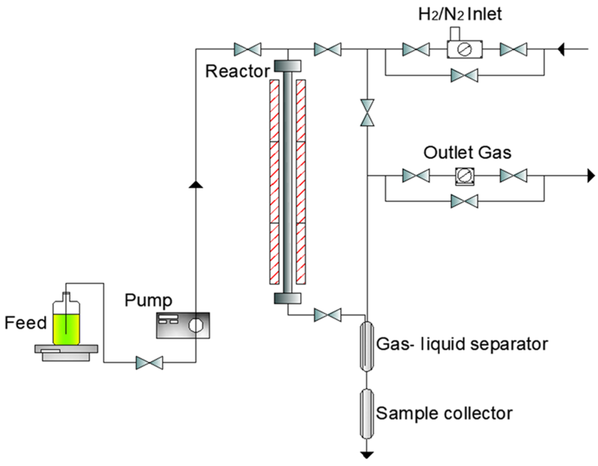
2.2. Experimental Setup and Experiments

To produce renewable fuels by blending, four mixtures of the diesel fraction of distilled FTS waxes were combined with commercial fossil diesel. The mixtures were prepared using different ratios of both products: 7:93, 15:85, 30:70, and 50:50 wt.%, to meet the EN590 norm for diesel fuels.
In the case of the heavy fraction (360–700 °C) of distilled FTS waxes, seven blends with VGO (90:10, 85:15, 80:20, 75:25, 70:30, 60:40, and 50:50) were tested, seeking a low viscosity (5.5 mPa·s at 100 °C) and a sulphur content of 1 wt.%. This point was necessary to ensure the product could be pumped appropriately and maintain the catalyst activity during hydrocracking.
The hydrocracking experiments, also understandable as a co-processing of the heavy fraction of distilled FTS waxes with VGO, were performed in a stainless-steel fixed-bed reactor (inner diameter (ID): 25 mm, length 820 mm). The reactor was equipped with electric heating and external/internal (thermoprobe ID: 6.25 mm) thermocouples to control the operating temperature in the catalytic bed accurately. Figure 1 shows a schematic diagram of the experimental unit.
The reactor was filled with carborundum (SiC), quartz wool, and catalyst (particle sizes 0.5–2.0 mm) according to the following procedure: First, quartz wool was added to the reactor, followed by SiC (1.0–2.0 mm) until it reached 270 mm (from the bottom of the reactor). Then, the catalyst was added. The catalytic bed comprised three parts of 20.0 g of catalyst diluted with fine SiC (0.1 mm) in 1:1, 1:2, and 1:3 (vol:vol). The catalyst concentration increased along the catalyst bed, maintaining the reactor temperature profile and isothermal state. Finally, the reactor was filled with quartz wool (5 mm) and SiC (1.0–2.0 mm). After catalyst loading, the reactor was flushed with N2 (600 NL/h, 100 kPa, and 25 °C) for 2 h, and the pressure was increased to 12.0 MPa to perform the leak test. After the leak test, the pressure was reduced to 10.0 MPa and the gas changed to H2 for the catalyst sulfidation. This procedure was performed according to the catalyst vendor’s instructions. After completing the catalyst activation, the feedstock was changed to VGO (WHSV = 1 h−1, T = 420 °C, and P = 10 MPa).
The operating conditions were the same as those used by the authors in a previous manuscript [37]. In the case of co-processing, the feed flow rate was changed from 60 g/h (WHSV = 1.0 h−1) to 30 g/h (WHSV = 0.5 h−1) to improve catalyst activity. During the hydrocracking experiment, density at 15 °C, refractive index, sulphur content, and nitrogen content were routinely monitored to control the catalyst activity and steady-state status.

2.3. Blending and Hydrocracking Products Analyses

In the case of blending experiments, the resulting mixtures of diesel fraction of distilled FTS waxes and fossil diesel were analysed in a similar way to the feedstocks; this means in terms of the EN590 norm.
Liquid and gaseous hydrocracking products were separated using a gas/liquid separator. Liquid sampling was carried out every three hours at WHSV = 1.0 h−1 or every six hours at WHSV = 0.5 h−1. Liquid products were also analysed according to EN590 standards. Moreover, some more specific analyses were included for the detailed determination of carbon distribution (n-d m method, FT-IR Nicolet IS10 spectrometer, Thermo Fisher, Prague, CZ, ASTM D3238 [38]), aromatic compound composition (High-Pressure Liquid Chromatography, Agilent Infinity 1260, Agilent, Santa Clara, CA, USA, IP391 standard [39], Agilent 2023) and detailed diesel fraction composition (GCxGC-MS, GCxGC-TOFMS instrument, LECO Corporation, St. Joseph, MI, USA). For this particular analysis, the procedure was as follows: 0.2 μL of the undiluted sample was injected at 320 °C (PTV injector, 20–320 °C, 720 °C/min) under a helium flow rate of 1 mL/min and a split ratio of 250:1. The temperature programme consisted of 1.5 min at 40 °C, subsequently ramped to 300 °C with a heating rate of 4 °C/min, and held at 300 °C for 10 min. The temperature of the detector was 250 °C. The primary column was Rxi-5SilMS, 30 m × 0.25 mm, with a diameter of 0.25 μm. The secondary column was Rxi-17SilMS, 1.3 m × 0.15 mm, with a diameter of 0.15 μm. The collected data was then evaluated using ChromaTOF software (ChromaTOF 2023, https://www.leco.com/product/chromatof-tile (accesed on 15 February 2024)).
The gaseous products were quantified using a mechanical gas flow meter and then sampled using Tedlar bags for offline analysis. The analysis was performed using an Agilent 7890 A gas chromatograph (GC) with Agilent’s refinery gas analysis method. The GC instrument had three work channels:
(i)
HayeSep Q column with a thermal conductivity detector (TCD) to measure H2, with N2 used as the carrier gas.
(ii)
HayeSep Q column with TCD to measure O2, N2, CO, CO2, H2S, and C1–C2 hydrocarbons, with He used as the carrier gas.
(iii)
5 A molecular sieve column with a flame ionisation detector to measure C1–C7 hydrocarbons, with He used as the carrier gas.

3. Results and Discussion

The FTS wax raw material contained a small amount of water, which was necessary to remove to avoid the malfunction of the distillation unit. Figure 2 shows the FTS wax raw material composition as determined by Simdis. According to these results, it is clear that the FTS wax is a paraffinic feedstock apparently compatible with petroleum feedstocks. Table 1 shows the basic properties of FTS raw material, together with boiling range fractions after water elimination and distillation (PILODIST, PETRODIST 500 Q (semi-automatic operation) PILODIST laboratory & process technology, Prague, Czech Republic)).
The FTS wax-distilled product was mainly composed of a diesel fraction (boiling point range (BPR): 180–360 °C) and a heavy fraction or residue (BPR: >360 °C). The diesel fraction was used for blending experiments with fossil diesel, and the heavy fraction was co-processed in hydrocracking conditions with vacuum gas oil (VGO) for renewable fuel production.

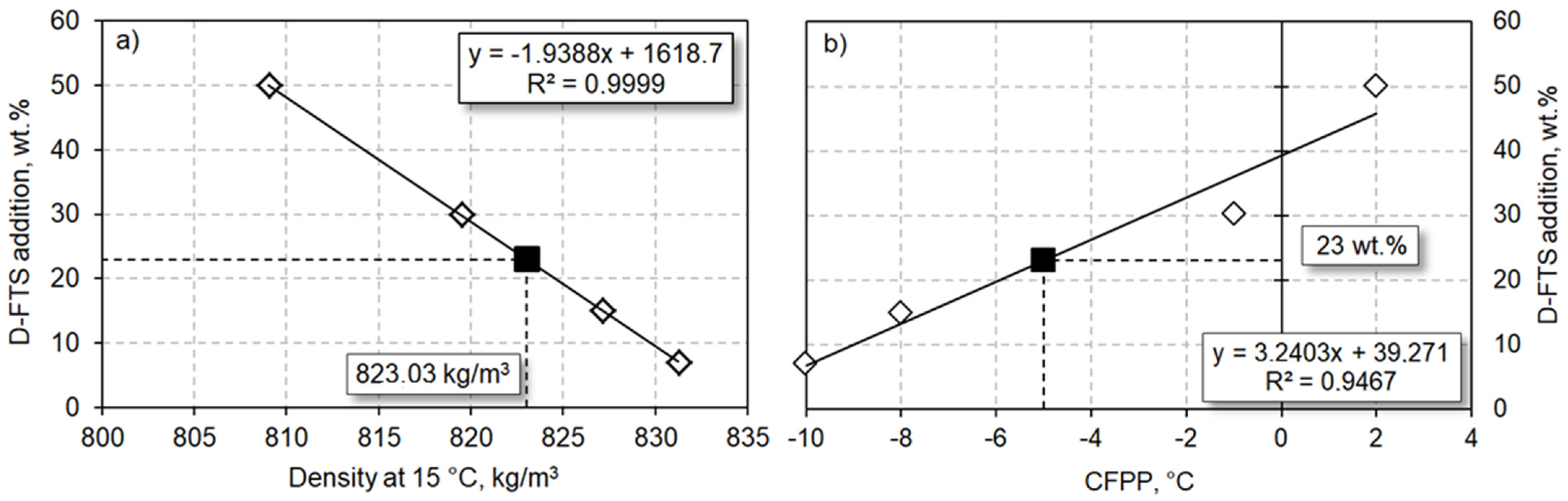
3.1. Blending Experiments

For this proposal, four mixtures of the diesel fraction of distilled FTS waxes (D-FTS) and fossil diesel (FD) were prepared: 7:93, 15:85, 30:70, and 50:50 wt.%. Table 2 shows the product characterisation for each mixture and EN590 norm values.
Adding D-FTS to FD significantly increased the cetane index and relative parameters (flash point and cetane number). Moreover, it also decreased the density, sulphur content, nitrogen content, and polyaromatic compounds. These effects were clearly due to the paraffin nature of FTS waxes (Figure 1). Similar behaviour has also been observed during the co-processing of vegetable oil (HVO) into middle distillates due to the increase of paraffin compounds [40,41].
Nevertheless, at the highest D-FTS:FD blending ratios (i.e., 30:70 and 50:50 wt.%), density and CPFF were entirely out of diesel fuel standards (i.e., 820–845 kg/m3; >0 °C). Thus, it is possible to claim that the maximal possible D-FTS addition to FD is a value between 15 and 29% wt.%. Two linear models based on experimental data were determined for CPFF and density. Figure 3 shows CFPP and density variation with the amount of D-FTS blended in the FD.
To determine the optimal ratio for the D-FTS:FD mixture, the trend of density and CFPP was evaluated with the D-FTS addition. A simple linear correlation (equations shown in the Figure 3) indicates that the most optimal ratio for D-FTS: FD mixture was 23:77 wt.%, which fulfils these two critical EN590 standards for diesel fuels (i.e., 820–845 kg/m3 and <0.0 °C, respectively).

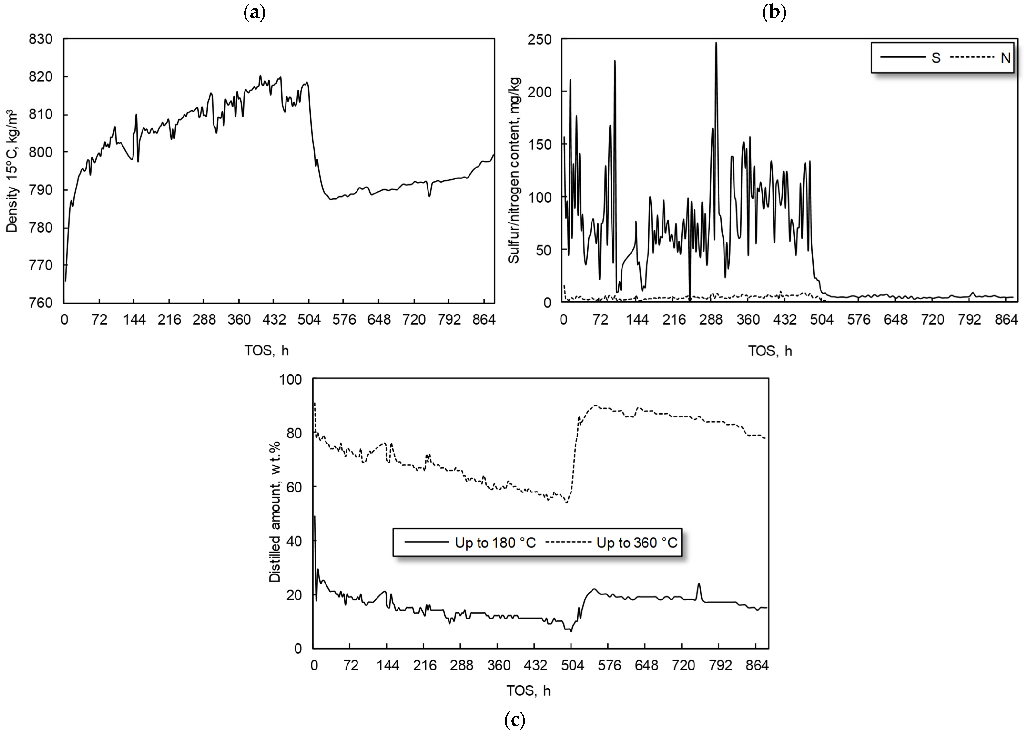
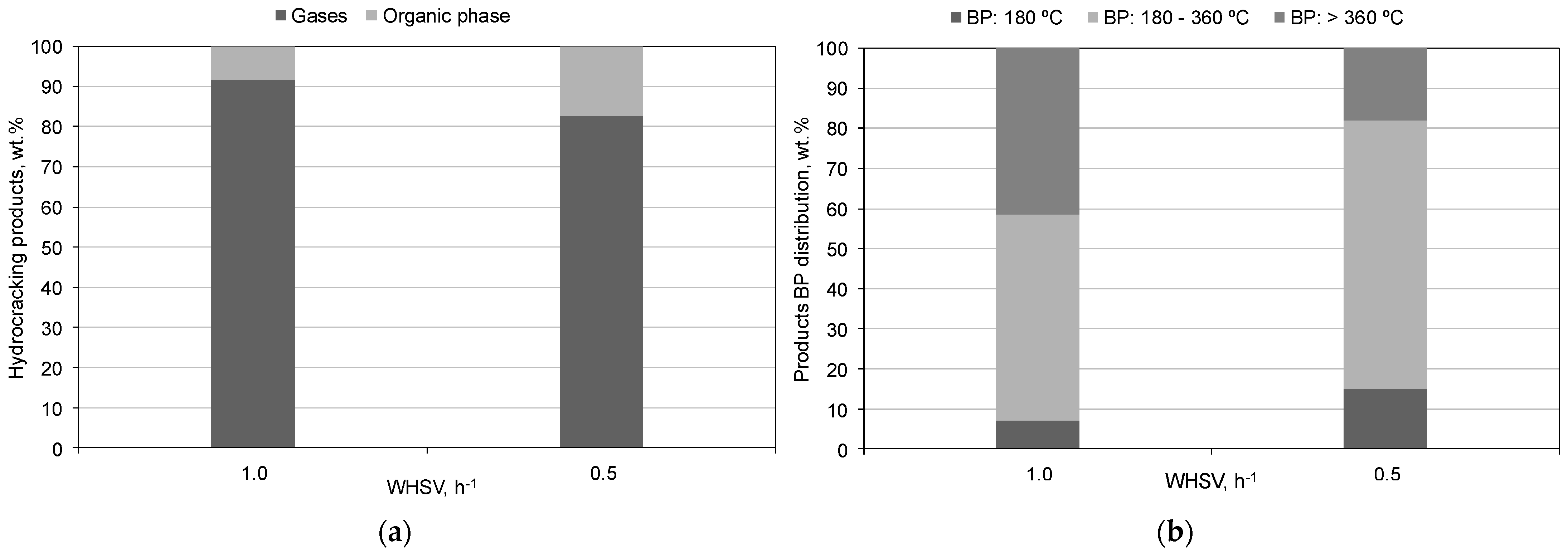
3.2. Hydrocracking Experiments

Before co-processing (i.e., hydrocracking with VGO), the heavy fraction of the distilled FTS waxes (H-FTS) was mixed with VGO in different ratios to analyse sulphur content and viscosity. This point is a key part of the experiment to ensure that the product can be adequately pumped through the unit and has enough sulphur to maintain the catalyst activity [42,43]. Table 3 shows a basic characterisation of VGO and its mixtures with H-FTS.
Table 3 reveals the importance of the VGO:H-FTS ratio in co-processing. A 50:50 wt.% ratio was found to meet the viscosity (~5.5 mm2/s) and sulphur content (>0.5 wt.%) requirements while also maximising the H-FTS percentage in the feed. This ratio was then co-processed at industrial hydrocracking conditions for over 36 days at two different WHSV’s (i.e., 0.5–1.0 h−1). Figure 4 provides a comprehensive view of the density, Simdis, sulphur content, and nitrogen content of the hydrocracking products obtained during the VGO:H-FTS co-processing.
There is a direct correlation between WHSV and catalyst activity. During the initial 500 h of the experiment (T = 420 °C, WHSV = 1.0 h−1, P = 10.0 MPa), the catalyst activity steadily declined. This led to hydrocracking products with increased density, sulphur content, nitrogen content, and a lower yield of diesel fraction compounds. To restore catalyst activity, WHSV was reduced from 1.0 to 0.5 h−1. This operational change significantly enhanced the catalyst activity from TOS 504 h, resulting in a hydrocracking product with lower product density (Figure 4a), lower sulphur and nitrogen content (S: <10 mg/kg; N: <5 mg/kg—Figure 4b), and a higher diesel fraction (BP: 180–360 °C = 67.1 wt.%—Figure 4c). A mass balance of products, along with product distillation, was performed to evaluate the quality of the diesel fraction of the hydrocracked product. Figure 5 presents the product distribution for each operational condition.
The decrease in WHSV throughout the experiment led to a significant increase in the percentage of diesel boiling point products, from 51.4 to 67.1 wt.%. This point was accompanied by a notable decrease in the undesired heavy fraction (Figure 5). Thus, this finding can be attributed to the longer contact time between the feedstock (VGO:H-FTS) and the hydrocracking catalysts, which in turn seems to enhance the catalyst activity. Therefore, it can be concluded that a lower WHSV is conducive to the production of transportation fuels in the diesel range, aligning with the research’s objective.
The gases from the reactor outlet had a similar composition for both WHSVs. Hydrogen (72.5 wt%) was the main compound, followed by methane (8.1 wt%), propane (3.4 wt%), n-butane (3.1 wt%), iso-pentane (2.3 wt%), and ethane (1.4 wt%). The changes in WHSV only affected the total amount of gas formation, but not the selectivity of the different products.
For a detailed characterisation of the diesel fraction of the hydrocracked product, the organic phase was physically distilled and re-analysed to compare the properties in terms of EN590, together with aromatic composition [44] and GCxGC-MS analysis. Table 4 shows the results of this detailed characterisation.
As expected by the experiment monitoring, the fuel quality of the diesel fraction produced at WHSV of 0.5 h−1 was much better than at WHSV of 1.0 h−1 in terms of cetane index and relative parameters. Moreover, the resulting transportation fuel fulfils the essential EN590 standards for diesel, including sulphur content, nitrogen content, and CFPP. The lower aromatics and paraffin content of the diesel fraction obtained at WHSV 0.5–1 h indicates a higher hydrogenation ratio of the feedstock. This result was also confirmed by the presence of naphthenes and a high content of isomers and cycloalkanes, which might be due to aromatic compound hydrogenation. The only exception to these promising results is the product density, which is lower than what is required by EN590. This fact was due to the different density of linear paraffin regarding the VGO compounds. However, this point might not be a significant issue and is easily solved by additive addition or fuel blending.

4. Conclusions

In this research, the aim was to study the production of transportation fuels from Fischer–Tropsch waxes by blending its diesel fraction with fossil diesel (7:93; 15:85; 30:70, and 50:50 wt.%) and by co-processing its heavy fraction with vacuum gas oil (T = 420 °C, WHSV = 0.5–1.0 h−1, P = 10.0 MPa). The resulting products were characterised and compared to diesel fuels. In the case of blending experiments, a mixture of 23:77 wt.% of the diesel fraction of the Fischer–Tropsch waxes led to a renewable transportation fuel that fulfilled the EN590 standards for commercial petroleum diesel. Higher blending values resulted in a significant deviation in critical parameters, such as density. In the case of hydrocracking experiments, the most striking results consisted of a significant drop in density, sulphur, and nitrogen content due to a feed rate decrease from 60 g/h (WHSV = 1.0 h−1) to 30 g/h (WHSV = 0.5 h−1). The co-processing of a heavy fraction of the Fischer–Tropsch waxes with vacuum gas oil in a ratio of 50:50 wt.% at WHSV 0.5 h−1 produced a rich paraffin-based renewable diesel that also meets the essential EN590 standards for diesel fuels, critical in the case of sulphur content, nitrogen content, and CFPP. Thus, according to this work, it is possible to claim the suitability of Fischer–Tropsch waxes for renewable transportation fuel production, either by the straight mixture of its diesel fraction with petroleum diesel fuels or hydrocracking of the heavy fraction with vacuum gas oil in a commercial unit of hydrotreatment.

Author Contributions

Conceptualisation, J.F. and J.M.H.H.; methodology, J.F. and M.B.; validation, J.G., Z.G. and H.d.P.C.; formal analysis, J.F.; investigation, J.M.H.H., M.B. and H.d.P.C.; resources, J.F. and J.G.; data curation, J.M.H.H. and H.d.P.C.; writing—original draft preparation, J.G. and J.M.H.H.; writing—review and editing, Z.G. and H.d.P.C.; visualisation, M.B.; supervision, J.M.H.H.; project administration, J.F.; funding acquisition, J.F. and M.B. All authors have read and agreed to the published version of the manuscript.

Funding

This publication is a result of the project CATAMARAN, Reg. No. CZ.02.1.01/0.0/0.0/16_013/0001801, which has been co-financed by European Union from the European Regional Development Fund through the Operational Programme Research, Development and Education. This project has also been financially supported by the Ministry of Industry and Trade of the Czech Republic which has been providing institutional support for long-term conceptual development of research organisation. The result was achieved using the infrastructure of the project Efficient Use of Energy Resources Using Catalytic Processes (LM2018119) which has been financially supported by MEYS within the targeted support of large infrastructures.

Institutional Review Board Statement

Not applicable.

Informed Consent Statement

Not applicable.

Data Availability Statement

The data presented in this study are available on request from the corresponding author. The data are not publicly available due to privacy.

Conflicts of Interest

Authors Jakub Frątczak, Joanna Górska, Martin Babor, Zahra Gholami, José Miguel Hidalgo Herrador was employed by the company ORLEN UniCRE a.s. The remaining authors declare that the research was conducted in the absence of any commercial or financial relationships that could be construed as a potential conflict of interest.

References

  1. De Rosa, M.; Gainsford, K.; Pallonetto, F.; Finn, D.P. Diversification, concentration and renewability of the energy supply in the European Union. Energy 2022, 253, 124097. [Google Scholar] [CrossRef]
  2. Solarin, S.A.; Sahu, P.K. Sectoral foreign direct investment and environmental degradation: New insights from diversification of energy mix containing fossil fuels and renewable energy. Environ. Sci. Pollut. Res. Int. 2023, 30, 91853–91873. [Google Scholar] [CrossRef] [PubMed]
  3. Aitken, C.; Ersoy, E. War in Ukraine: The options for Europe’s energy supply. World Econ. 2023, 46, 887–896. [Google Scholar] [CrossRef]
  4. Sotiriou, C.; Zachariadis, T. Optimal Timing of Greenhouse Gas Emissions Abatement in Europe. Energies 2019, 12, 1872. [Google Scholar] [CrossRef]
  5. Kazancoglu, Y.; Ozbiltekin-Pala, M.; Ozkan-Ozen, Y.D. Prediction and evaluation of greenhouse gas emissions for sustainable road transport within Europe. Sustain. Cities Soc. 2021, 70, 102924. [Google Scholar] [CrossRef]
  6. Jankuj, V.; Spitzer, S.H.; Krietsch, A.; Štroch, P.; Bernatík, A. Safety of alternative energy sources: A review. Chem. Eng. Trans. 2022, 90, 115–120. [Google Scholar] [CrossRef]
  7. Hagem, C.; Kallbekken, S.; Mæstad, O.; Westskog, H. Enforcing the Kyoto Protocol: Sanctions and strategic behavior. Energy Policy 2005, 33, 2112–2122. [Google Scholar] [CrossRef]
  8. Wysokińska, Z. A Review of Transnational Regulations in Environmental Protection and the Circular Economy. Comp. Econ. Res. Cent. East. Eur. 2020, 23, 149–168. [Google Scholar] [CrossRef]
  9. Shao, S.; Hu, Z.; Cao, J.; Yang, L.; Guan, D. Environmental Regulation and Enterprise Innovation: A Review. Bus. Strateg. Environ. 2020, 29, 1465–1478. [Google Scholar] [CrossRef]
  10. European Commission. Commission Communication: Stepping up Europe’s 2030 Climate Ambition Investing in a Climate-Neutral Future for the Benefit of Our People. Available online: https://eur-lex.europa.eu/resource.html?uri=cellar:749e04bb-f8c5-11ea-991b-01aa75ed71a1.0001.02/DOC_2&format=PDF (accessed on 9 May 2024).
  11. European Environment Agency. Greenhouse Gas Emissions from Transport in Europe. Available online: https://www.eea.europa.eu/en/analysis/indicators/greenhouse-gas-emissions-from-transport (accessed on 13 July 2021).
  12. Martinelli, M.; Gnanamani, M.K.; LeViness, S.; Jacobs, G.; Shafer, W.D. An overview of Fischer-Tropsch Synthesis: XtL processes, catalysts and reactors. Appl. Catal. A Gen. 2020, 608, 117740. [Google Scholar] [CrossRef]
  13. Van Vliet, O.P.R.; Faaij, A.P.C.; Turkenburg, W.C. Fischer-Tropsch diesel production in a well-to-wheel perspective: A carbon, energy flow and cost analysis. Energy Convers. Manag. 2009, 50, 855–876. [Google Scholar] [CrossRef]
  14. Vosoughi, V.; Badoga, S.; Dalai, A.K.; Abatzoglou, N. Modification of mesoporous alumina as a support for cobalt-based catalyst in Fischer-Tropsch synthesis. Fuel Process. Technol. 2017, 162, 55–65. [Google Scholar] [CrossRef]
  15. Bezergianni, S.; Dimitriadis, A. Comparison between different types of renewable diesel. Renew. Sustain. Energy Rev. 2013, 21, 110–116. [Google Scholar] [CrossRef]
  16. Yang, C.; Liu, L.; Zhu, G.; Xie, C.; Zhang, X.; Zhang, X. Catalytic Cracking of Fischer-Tropsch Wax on Different Zeolite Catalysts. Catalysts 2023, 13, 1223. [Google Scholar] [CrossRef]
  17. Karaba, A.; Rozhon, J.; Patera, J.; Hájek, J.; Zámostný, P. Fischer-Tropsch Wax from Renewable Resources as An Excellent Feedstock For The Steam-Cracking Process. Chem. Eng. Technol. 2021, 44, 329–338. [Google Scholar] [CrossRef]
  18. Murat, M.; Gholami, Z.; Šimek, J.; Rodríguez-Padrón, D.; Hidalgo-Herrador, J.M. Rendering Fat and Heavy Fischer-Tropsch Waxes Mixtures (0–100%) Fast Pyrolysis Tests for the Production of Ethylene and Propylene. Processes 2021, 9, 367. [Google Scholar] [CrossRef]
  19. Kubička, D.; Černý, R. Upgrading of Fischer–Tropsch Waxes by Fluid Catalytic Cracking. Ind. Eng. Chem. Res. 2012, 51, 8849–8857. [Google Scholar] [CrossRef]
  20. Leckel, D. Noble Metal Wax Hydrocracking Catalysts Supported on High-Siliceous Alumina. Ind. Eng. Chem. Res. 2007, 46, 3505–3512. [Google Scholar] [CrossRef]
  21. Peng, C.; Du, Y.; Feng, X.; Hu, Y.; Fang, X. Research and development of hydrocracking catalysts and technologies in China. Front. Chem. Sci. Eng. 2018, 12, 867–877. [Google Scholar] [CrossRef]
  22. Frątczak, J.; de Paz Carmona, H.; Tišler, Z.; Hidalgo Herrador, J.M.; Gholami, Z. Hydrocracking of Heavy Fischer–Tropsch Wax Distillation Residues and Its Blends with Vacuum Gas Oil Using Phonolite-Based Catalysts. Molecules 2021, 26, 7172. [Google Scholar] [CrossRef]
  23. Pleyer, O.; Vrtiška, D.; Straka, P.; Šimáček, P. Co-processing of BTL Fischer-Tropsch wax and heavy vacuum gas oil. Renew. Energy 2024, 225, 120276. [Google Scholar] [CrossRef]
  24. Šimáček, P.; Kubička, D.; Pospíšil, M.; Rubáš, V.; Hora, L.; Šebor, G. Fischer–Tropsch Product as A Co-Feed for Refinery Hydrocracking Unit. Fuel 2013, 105, 432–439. [Google Scholar] [CrossRef]
  25. Halmenschlager, C.M.; Brar, M.; Apan, I.T.; de Klerk, A. Hydrocracking vacuum gas oil with wax. Catal. Today 2020, 353, 187–196. [Google Scholar] [CrossRef]
  26. Hodala, J.L.; Jung, J.-S.; Yang, E.-H.; Hong, G.H.; Noh, Y.S.; Moon, D.J. Hydrocracking of FT-wax to fuels over non-noble metal catalysts. Fuel 2016, 185, 339–347. [Google Scholar] [CrossRef]
  27. Stratiev, D.; Shishkova, I.; Ivanov, M.; Dinkov, R.; Georgiev, B.; Argirov, G.; Atanassova, V.; Vassilev, P.; Atanassov, K.; Yordanov, D.; et al. Catalytic Cracking of Diverse Vacuum Residue Hydrocracking Gas Oils. Chem. Eng. Technol. 2021, 44, 997–1008. [Google Scholar] [CrossRef]
  28. Xing, T.; De Crisci, A.G.; Chen, J. Hydrocracking of Fischer-Tropsch wax and its mixtures with heavy vacuum gas oil. Can. J. CHem. Eng. 2019, 97, 1515–1524. [Google Scholar] [CrossRef]
  29. Yang, M.; Zhang, L.; Wang, G.; Chen, Z.; Han, J.; Gao, C.; Gao, J. Fischer-Tropsch wax catalytic cracking for the production of low olefin and high octane number gasoline: Experiment and molecular level kinetic modeling study. Fuel 2021, 303, 121226. [Google Scholar] [CrossRef]
  30. ČSN EN 590; Motor fuels - Diesel fuel - Technical requirements and test methods ČSN EN 590 CORRECTION 1 65 6506. Original in Czech language: ČSN EN 590, Motorová paliva – Motorové nafty – Technické požadavky a metody zkoušení ČSN EN 590 OPRAVA 1 65 6506; Czech Standardization Agency: Prague, Czech Republic.
  31. ASTM D4052; Standard Test Method for Density, Relative Density, and API Gravity of Liquids by Digital Density Meter. ASTM International: West Conshohocken, PA, USA, 2022.
  32. ASTM D5291; Standard test methods for instrumental determination of carbon, hydrogen, and nitrogen in petroleum products and lubricants. ASTM International: West Conshohocken, PA, USA, 2016.
  33. ASTM D5453; Standard Test Method for Determination of Total Sulfur in Light Hydrocarbons, Spark Ignition Engine Fuel, Diesel Engine Fuel, and Engine Oil by Ultraviolet Fluorescence. ASTM International: West Conshohocken, PA, USA, 2016.
  34. ASTM D4629; Standard Test Method for Trace Nitrogen in Liquid Petroleum Hydrocarbons by Syringe/Inlet Oxidative Combustion and Chemiluminescence Detection. ASTM International: West Conshohocken, PA, USA, 2012.
  35. ASTM D2887; Standard Test Method for Boiling Range Distribution of Petroleum Fractions by Gas Chromatography. ASTM International: West Conshohocken, PA, USA, 2023.
  36. Hidalgo, J.M.; Horaček, J.; Matoušek, L.; Vráblík, A.; Tišler, Z.; Černý, R. Catalytic Hydrocracking of Vacuum Residue and Waste Cooking Oil Mixtures. Monatsh. Chem. 2018, 149, 1167–1177. [Google Scholar] [CrossRef]
  37. Hidalgo Herrador, J.M.; Psenička, M.; Horaček, J.; Tišler, Z.; Vráblík, A.; Černý, R.; Murat, M. Co-Processing Of Waste Cooking Oil And Light Cycle Oil With Niw/(Pseudoboehmite + Sba-15). Catalyst. Chem. Eng. Technol. 2019, 42, 512–517. [Google Scholar] [CrossRef]
  38. ASTM D3238; Standard Test Method for Calculation of Carbon Distribution and Structural Group Analysis of Petroleum Oils bu the n-d-M Method. ASTM International: West Conshohocken, PA, USA, 2017.
  39. IP 391; Petroleum Products—Determination of Aromatic Hydrocarbon Types in Middle Distillates—High Performance Liquid Chromatography Method with Refractive Index Detection. Energy Institute: London, UK, 2019.
  40. de Paz Carmona, H.; Vráblík, A.; Hidalgo Herrador, J.M.; Velvarská, R.; Cerný, R. Animal fats as a suitable feedstock for co-processing with atmospheric gas oil. Sustain. Energy 2021, 5, 4955–4964. [Google Scholar] [CrossRef]
  41. Bezergianni, S.; Dimitriadis, A.; Kikhtyanin, O.; Kubička, D. Refinery co-processing of renewable feeds. Prog. Energ. Combust. 2018, 68, 29–64. [Google Scholar] [CrossRef]
  42. Kubička, D.; Horáček, J. Deactivation of HDS catalysts in deoxygenation of vegetable oils. Appl. Catal. A Gen. 2011, 394, 9–17. [Google Scholar] [CrossRef]
  43. Horáček, J.; Kubička, D. Bio-oil Hydrotreating over conventional CoMo & NiMo catalysts: The role of reaction conditions and additives. Fuel 2017, 198, 49–57. [Google Scholar] [CrossRef]
  44. Hosseinifar, P.; Shahverdi, H. Development of A Generalized Model for Predicting the Composition of Homologous Groups Derived from Molecular Type Analyses to Characterize Petroleum Fractions. J. Petrol. Sci. Eng. 2021, 204, 108774. [Google Scholar] [CrossRef]
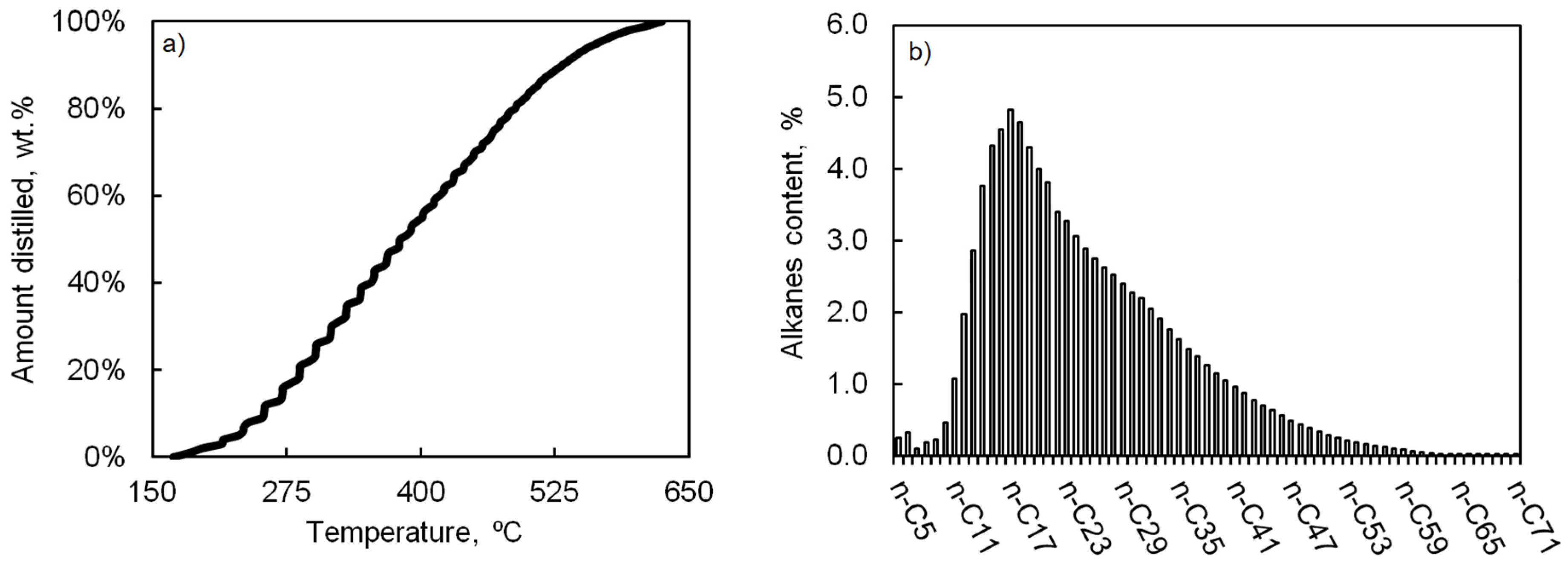
Figure 1. Schematic diagram of the experimental unit used for hydrocracking experiments. In this diagram, arrows indicate the sense of the flow. The red lines around the reactor indicate the unit’s electric heating.
Applsci 14 04656 g001
Figure 2. Simdis analysis of Fischer–Tropsch waxes raw material; (a) amount distilled (wt.%) vs. boiling temperature (°C); (b) Alkane content (%) vs. alkanes (e.g., n-C17 means a n-paraffin with 17 carbon atoms in its chain).
Applsci 14 04656 g002
Figure 3. Properties of fossil diesel and diesel fractions of Fischer–Tropsch waxes (D-FTS) and their linear correlation: (a) D-FTS addition (wt.%) vs. density at 15 °C (kg/m3); (b) D-FTS addition (wt.%) vs. CFPP (°C).
Applsci 14 04656 g003
Figure 4. Properties of hydrocracking products obtained during VGO:H-FTS co-processing at T = 420 °C, WHSV = 0.5–1.0 h−1, P = 10.0 MPa; (a) Density at 15 °C (kg/m3) vs. TOS (h); (b) Sulphur content (mg/kg) vs. TOS (h); (c) Nitrogen content (mg/kg) vs. TOS (h).
Applsci 14 04656 g004
Figure 5. (a) Product distribution (wt.%) for WHSV 0.5 and 1.0 h−1; (b) Boiling point distribution of the organic phase (wt.%—operating conditions: T = 420 °C, P = 10.0 MPa).
Applsci 14 04656 g005
Table 1. Basic feedstock properties of Fischer–Tropsch waxes raw material and boiling range fractions Fischer–Tropsch waxes after water elimination and distillation.
PropertiesFTS Wax Raw Material *FTS Wax without Light Compounds and Water *FTS Wax Distillation Product **
S content, mg/kg2.2N/AN/A
N content, mg/kg83.7N/AN/A
Elemental analysis
C content, wt.%80.8N/AN/A
H content, wt.%14.1N/AN/A
Boiling range fraction
Gasoline (<180 °C)1.00.00.0
Diesel (180–360 °C)42.039.038.0
Heavy/residue (>360 °C)57.061.058.0
Losses (wt.%)0.00.04.0
* Simdis; ** PILODIST distillation.
Table 2. Basic properties of fossil diesel and its mixtures with the diesel fraction of distilled Fischer–Tropsch waxes.
AnalysisFossil DieselMix 1
D-FTS:FD
7:93
Mix 2
D-FTS:FD
15:85
Mix 3
D-FTS:FD
30:70
Mix 4
D-FTS:FD
50:50
Diesel Fuel Standards EN590
Min.Max.
Density at 15 °C, kg/m3834.9831.2827.2819.5809.1820845
Kinematic viscosity at 40 °C, mm2/s2.62.62.72.72.92.04.5
Sulphur content, mg/kg8.16.35.35.14.4N/A10.0
Nitrogen content, mg/kg20.923.825.730.838.0N/AN/A
Poliaromatics, wt.%8.07.37.06.75.3N/A8.0
Elemental analysis (wt.%)
Carbon content86.786.486.686.485.9N/AN/A
Hydrogen content13.213.613.313.514.2N/AN/A
Distillation
Evaporates at 250 °C:4040403030N/A65
Evaporates at 350 °C:1001001009710085N/A
95% evaporated at:345.8345.5342.5342.3339.6N/A360
Cetane index505355606746N/A
Cetane number535457647351N/A
Flash point, °C686871737755N/A
Refractive index1.46241.46111.45951.45371.4494N/AN/A
Water content, wt.%<0.01<0.01<0.01<0.01<0.01N/A0.02
Impurities, mg/kg0.811.190.620.830.84N/A24
Oxidity stabilisation, h28.629.323.323.729.420N/A
Colour ASTM D 15000.90.90.90.80.7N/A2.0
CPFF−12−10−8−12N/A*
* Summer diesel (max. 0 °C), transition diesel (max. −10 °C), winter diesel (max. −20 °C).
Table 3. Basic characterisation of VGO and its mixtures with the heavy fraction of distilled Fischer–Tropsch waxes.
AnalysisVGOVGO:H-FTS
(10:90)
VGO:H-FTS
(20:80)
VGO:H-FTS
(30:70)
VGO:H-FTS
(40:60)
VGO:H-FTS
(50:50)
Density at 15 °C, kg/m3905.0908.6908.2907.8907.4907.0
Kinematic viscosity at 100 °C, mm2/sN/A10.308.877.736.675.51
Sulphur content, mg/kg1.92<0.05<0.050.180.260.63
Nitrogen content, mg/kg847N/AN/AN/AN/AN/A
Elemental analysis (wt.%)
Carbon content84.986.085.886.386.186.2
Hydrogen content12.114.014.013.914.013.7
H/C ratio1.41.941.951.921.941.89
Distillation
IBP, °C284.0315.1303.7298.2294.2293.8
FBP, °C510.3719.3719.7708.4689.0643.7
BMCI/CI *N/A39.240.040.842.442.7
* BMCI/CI = 473.7·SG − 456.8 + (48640/Tb); (SG, specific gravity-kg/m3; Tb, average boiling point-K).
Table 4. Detailed characterisation of the diesel fraction from the product of the VGO:H-FTS co-processing at different WHSV (operating conditions: T = 420 °C, WHSV = 0.5–1.0 h−1, P = 10.0 MPa).
AnalysisDiesel Fraction
HC Product
WHSV 0.5 h−1
Diesel Fraction
HC Product
WHSV 1.0 h−1
Diesel Fuel Standards EN590
Min.Max.
Density at 15 °C, kg/m3799.3811.5820820
Kinematic viscosity at 40 °C, mm2/s2.773.382.02.0
Sulphur content, mg/kg2.538.1N/AN/A
Nitrogen content, mg/kg1.022.69N/AN/A
Elemental analysis, wt.%
Carbon content85.686.5N/AN/A
Hydrogen content14.513.4N/AN/A
Distillation
-Evaporates at 250 °C:3020N/A65
Evaporates at 350 °C:1009085N/A
95% evaporated at:337.3356.2N/A360
Cetane index706846N/A
Cetane number686751N/A
Flash point, °C889355N/A
Refractive index1.44311.4498N/AN/A
Water content, wt.%<0.01<0.01N/A0.02
Impurities, mg/kg2.044.18N/A24
Oxidity stabilisation, h>48>4820N/A
Colour ASTM D 15000.30.5N/A2.0
CPFF−20−1N/A*
n-d m method, wt.%
Aromatic Carbon4.66.6N/AN/A
Naphthenic Carbon25.522.4N/AN/A
Paraffinic Carbon55.557.5N/AN/A
Mono-aromatics7.712.3N/AN/A
Di-aromatics1.01.7N/AN/A
Poly-aromatics0.20.4N/A8.0
Total aromatics8.914.4N/AN/A
GCxGC-MS analysis, %
n-alkanes13.2917.71N/AN/A
i-alkanes66.1763.98N/AN/A
Alkenes + cycloalkanes16.0312.22N/AN/A
Aromatics3.284.86N/AN/A
Undefined compounds1.241.24N/AN/A
* Summer diesel (max. 0 °C), transition diesel (max. −10 °C), winter diesel (max. −20 °C).
Disclaimer/Publisher’s Note: The statements, opinions and data contained in all publications are solely those of the individual author(s) and contributor(s) and not of MDPI and/or the editor(s). MDPI and/or the editor(s) disclaim responsibility for any injury to people or property resulting from any ideas, methods, instructions or products referred to in the content.

