Article

The Role of Delays in the Performance of Blasting

1
Department of Metallurgical and Mining Engineering, Universidad Catolica del Norte, Antofagasta 1270398, Chile
2
Department of Environment, Land and Infrastructure Engineering, Politecnico di Torino, 10129 Torino, Italy
3
Department of Metallurgical and Materials Engineering, Universidad Tecnica Santa Maria, Santiago 8940897, Chile
*
Author to whom correspondence should be addressed.
Appl. Sci. 2024, 14(11), 4657; https://doi.org/10.3390/app14114657
Submission received: 9 May 2024 / Revised: 27 May 2024 / Accepted: 28 May 2024 / Published: 28 May 2024

Abstract

:
When researching rock blasting, the design parameters typically used for analysis are the geometric and charging parameters. This study focuses on a different approach based on the effect of timing, specifically the role of delays in the initiation sequence. Data were obtained from the results of full-scale blasts. The experimental setting and location allowed us to consider all parameters, other than the number of delays, as constants. The experimental results were analyzed, relating the delay variables to the fragmentation and KPIs of downstream operations. It was found that increasing the number of delays per unit of blasted rock and reducing simultaneous adjacent holes produces finer fragmentation, reduces the amount of fines, facilitates secondary operations, and reduces the risk of flyrock.

1. Introduction

When analyzing the performance of rock blasting, the geometric (bench characteristics, drill mesh, and hole length) and charging (specific charge, position of charges, bottom and column charge, and decking) parameters dominate the design and prediction models. Meanwhile, research on the influence of timing on rock fragmentation and downstream operations has not yet been fully developed [1].
Some previous studies on the effects of timing on rock fragmentation were based on small-scale test blasts [2,3,4,5]. In Ref. [2], small-scale tests on dolomite benches were performed, using 0 to 45 ms delay intervals, equivalent to 0 to 118 ms/m of burden. Delay intervals of 3 to 56 ms/m of burden obtained the smallest particle sizes, while coarse fragmentation resulted from short delays (<3 ms/m). In the short delay configuration, the breakage mechanism was similar to that of pre-splitting; that is, fractures connecting the blastholes and large blocks in the burden region. Coarse fragmentation also resulted from long delays (>57 ms/m); in this case, there was no cooperation between charges, and the blastholes broke the rock independently. In Ref. [3], the role of gas flow between fractures caused by the stress wave induced by the explosive was considered. In Ref. [4], small-scale blasts in hard Canadian granite were performed. Coarse fragmentation was observed, but the average fragment size did not change much once small delays were used. In Ref. [5], drop tests were performed to study the material’s grindability on three granites, comparing blasted and unblasted specimens. Blasting appeared to reduce the work index by 5–11%. In Ref. [6], eight experiments were conducted on granite bench blasting models employing double holes with delay times ranging from approximately 13 to 300 ms. The study identified an “optimal” inter-hole delay of 200 µs, where simultaneous detonation reduced the median size by approximately 14.5%. The same authors in Ref. [7] conducted a similar test and found that, compared to short delay times such as 27.36 µs, x50 was improved by approximately 25% at a delay time of 180 µs. The results indicated a notable difference and substantial improvement in fragmentation when the delay times fell within the range of no-shockwave interaction. In Ref. [8], full-scale tests were conducted on short-delay blasting using electronic detonators to enhance the tensile effect of the stress wave tail. Field experiments revealed a 45.6% improvement in the mean size of fragments compared to blasts with longer delay times. The authors in [9,10] proposed an analytical solution for predicting the supersonic detonation of a cylindrically shaped explosive charge, which is suitable for numerical methods. To validate the model, the authors conducted tests to investigate stress wave expansion from a detonating borehole and stress wave interactions with geological features such as discontinuities, interfaces, and cracks. Similar outputs were found by [11]. The research described in [12,13] involved conducting tests in an open-pit limestone quarry, confirming that the right selection of delay timing can enhance fragmentation and, consequently, improve subsequent extraction processes. The study in [14] showed that energy consumption at the primary crusher is the sum of two components depending on the distribution of the muckpile: The energy used for mechanical crushing and the energy used for winning the inertial resistances. The limitations of electronic detonators were studied in [15], where it was commented that the delay time and initiation accuracy are not typical governing factors for blast performances. The author of [16] agreed with that of [15] in that interacting stress waves have a local impact that is insignificant at the scale of the volume of fragmentation; therefore, a very short delay does not generate significant changes in fragmentation. The experimental results obtained in [16] and the numerical results in [17] are in agreement with [15], showing no significative differences in fragmentation with shockwave interactions compared to that without shockwave interactions.
This research investigates the role of delays and delay density in blasts using a full-scale experimental approach. The delay time remained constant at 42 ms, as explained in the next section. Therefore, this study focuses on the performance of different delay times and the interactions of shockwaves at different timings.

2. Materials and Methods

This research was conducted at the Experimental Mine of the University of Sao Paulo, Brazil. The research constants were as follows:
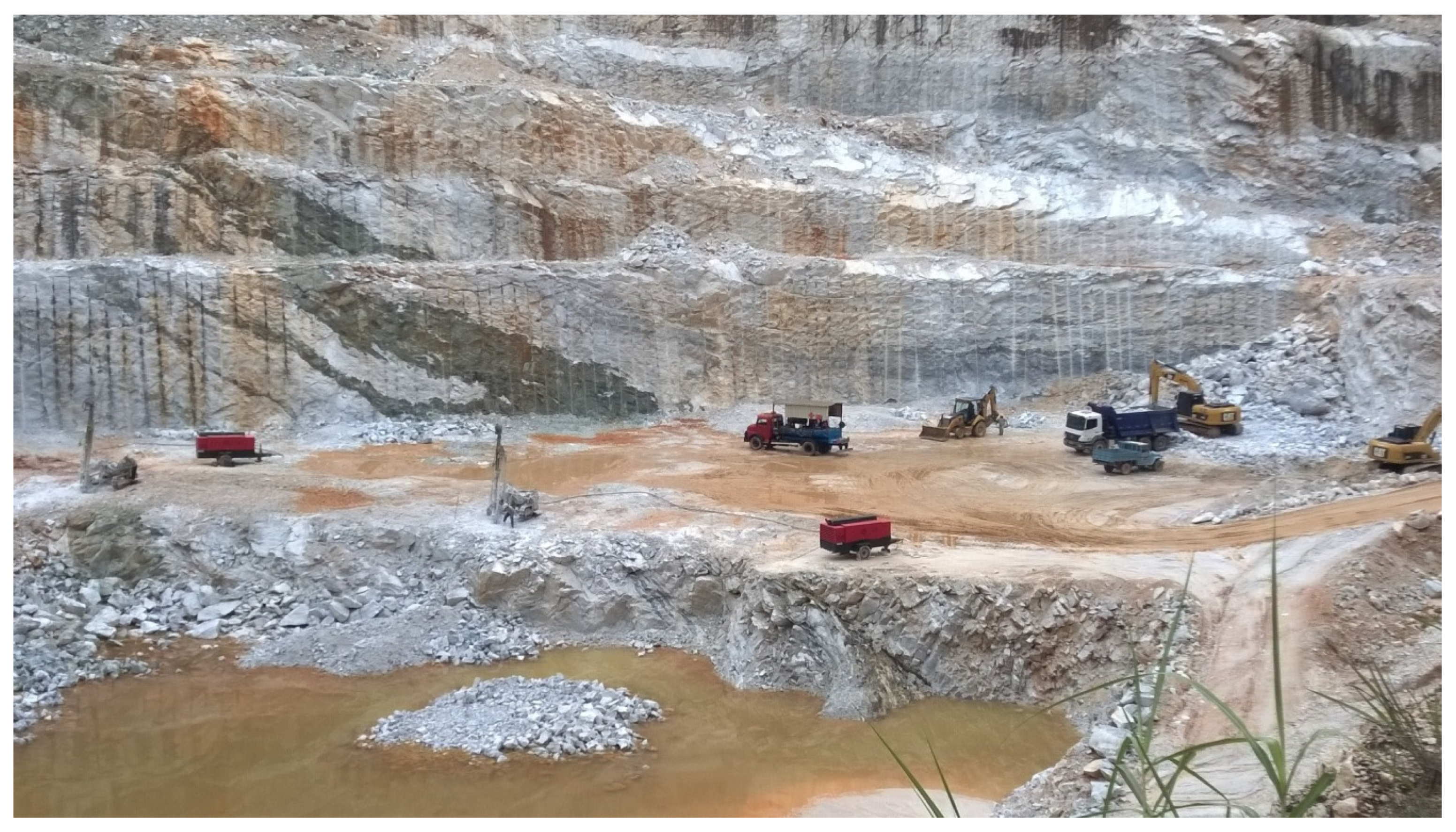
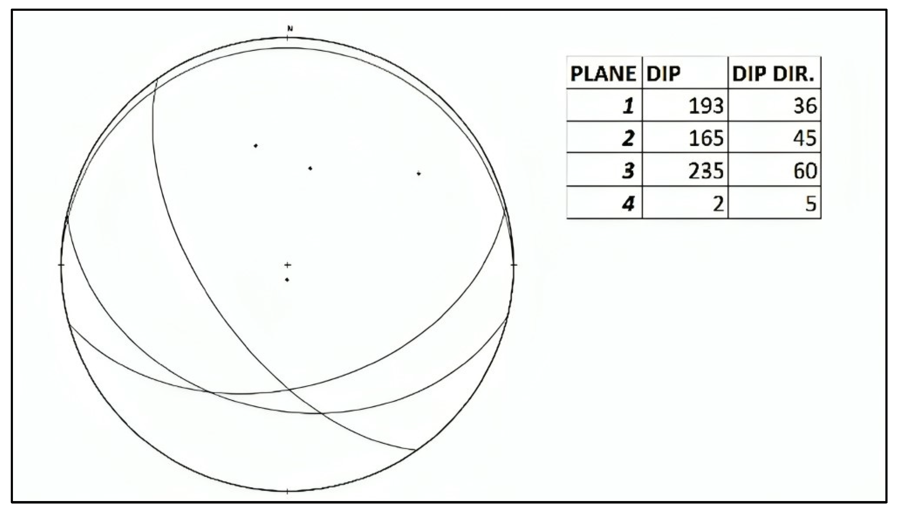
  • The rock and rock mass: dolomitic marble, moderately fractured.
  • The explosive: emulsion explosive under the commercial name DINAPEX, by manufacturer DINCON (Estrela, Brasil). Density of 1.15 g/cm3, nominal VOD of 5200 m/s. In cartridges, 64 mm in diameter.
  • The hole diameter: 76 mm.
  • The initiation system: detonating cord, 10 g/m.
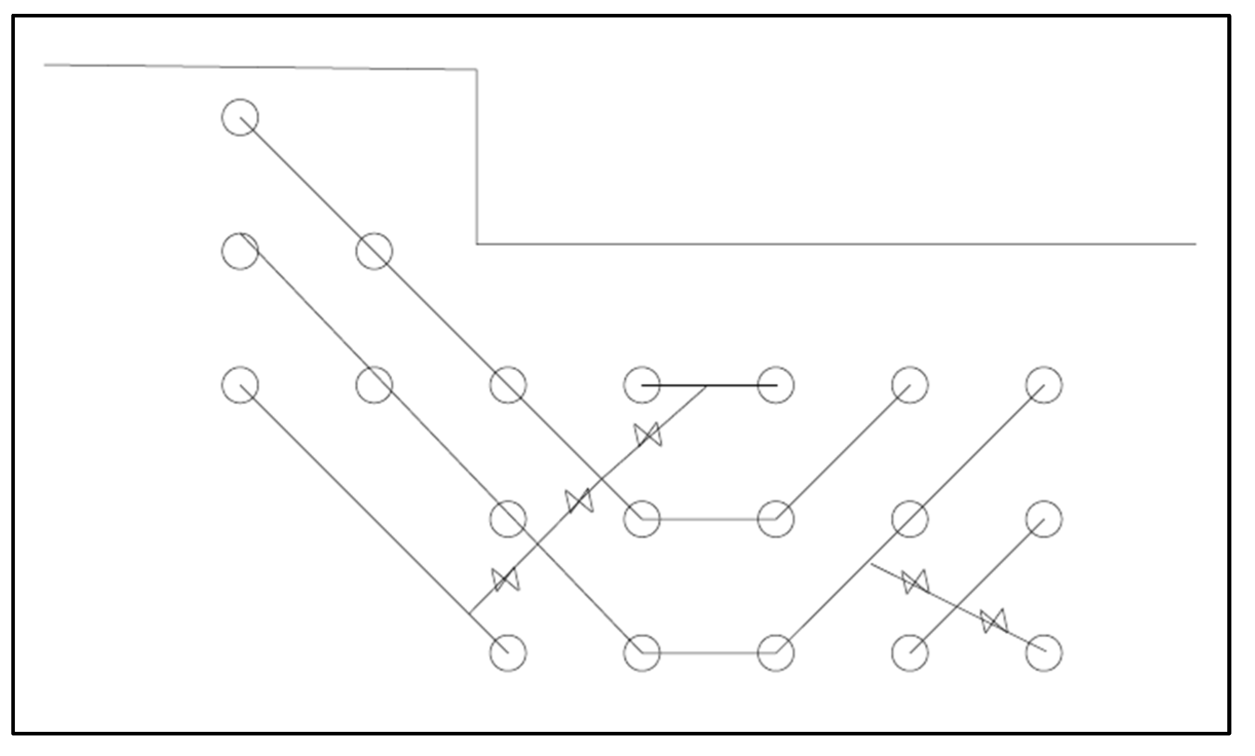
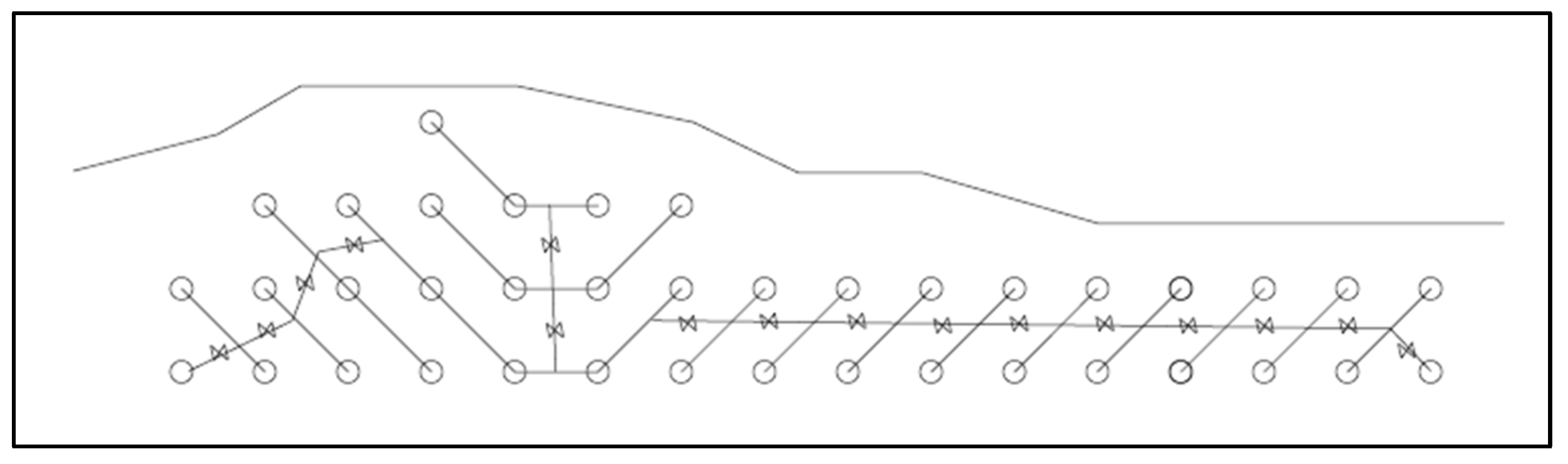
  • The sequencing system: pyrotechnic connectors for det cord with a delay of 42 ms.
  • The height of the benches: approximately 9 m; consequently, the depth of the holes was approximately 10 m, with a 0.9 m underdrilling design (taking into account field conditions that may affect the effective height of the benches and thus the length of the holes).
  • The charge per hole: 30 kg of cartridge emulsion.
It must be noted that the scattering of the real-time delays around their nominal times was considered an unavoidable systematic experimental error present throughout all experiments. Therefore, analyses such as those detailed in [18] were not conducted.
Figure 1 and Figure 2 show two examples of blast plans with a typical distribution of delays, as used during the research. All the experimental blasts took place at the last level of the benches above the quarry floor; a panoramic view of this sector of the quarry is shown in Figure 3.
All the blast tests took place at short distances one from one another; therefore, the experimental medium (rock mass) can be considered a constant. The characteristics of the intact rock are shown in Table 1, in which the ultimate compression strength (UCS), Schmidt hammer rebound, and corrected point load test value (Is50) are reported. The main sets of discontinuities present in the rock mass are shown in Figure 4.
Key performance indicators (KPIs) were collected and used to analyze the results. Said KPIs are reported in Table 2, where detailed descriptions are given. Similar KPIs were used by [13,14].

3. Results

The results are summarized in charts reported in Figure 5, Figure 6, Figure 7, Figure 8, Figure 9, Figure 10, Figure 11 and Figure 12. Each chart features a dashed line, not representing linear regression but serving as a visual indicator of the data trend on the scatterplot.
The incidence of the use of a hydraulic secondary breaker, quantified by Sb, serves as an indicator of the quality of fragmentation: the fewer hours that the hydraulic hammer operated per unit of volume of blasted rock, the better the fragmentation. Figure 5 shows the increase in hydraulic hammer usage with the increasing number of adjacent holes blasted with the same delay.
The experimental data points reported in Figure 6 show that as the blasthole density increased with a D larger than 3 m (number of blastholes with D > 3 m, normalized with respect to the total number of blastholes tended toward 1), the value of Sb decreased considerably, with some experimental points approaching 0.
On the contrary, Figure 7 shows that increasing the density of blastholes with D = 2 m resulted in an approximately proportional increase in the quantity of fines produced. In other words, increasing the distance between simultaneous holes led to a better distribution of explosive energy, resulting in more homogeneous fragmentation and a lower fine content.
These combined results suggest that achieving better blast decomposition by increasing the distance between simultaneous holes can redirect the explosive force along the burden toward the free surface, instead of through the spacing between holes. This leads to more homogeneous fragmentation, reducing the production of coarser material while also preventing an excess of fines.
Figure 8 shows a decrease in the percentage of fines with an increase in delay density. Under the same conditions, an increase in SP dramatically decreased the particle size, quantified through P80 in the present study, as depicted in the trend shown in Figure 9.
These combined results indicate the same behavior as discussed above: Managing a better decomposition of the blast by increasing the distance between simultaneous holes can induce the explosive to work along the burden toward the free surface instead of through the spacing between holes, obtaining a more homogeneous fragmentation that reduces the production of coarser material while also preventing an excess of fines. On the contrary, simultaneous holes at close distances can result in the cooperation of charges along the line connecting the two hole axes. This may induce the explosive energy to work along the surface between the holes with a shearing effect, instead of producing fragmentation. Increasing the distance between simultaneous holes reduces the likelihood of creating a shearing effect, directing the explosive energy to work along the line of least energy (the burden) to promote fragmentation.
Considering the downstream processes, as mentioned before, the frequency of hydraulic secondary breaker usage serves as an indicator of fragmentation quality. According to the experimental points in Figure 10, a higher SP resulted in reduced usage of a hydraulic hammer for secondary breaking. This observation aligns with the trend depicted in Figure 11: The higher the specific priming, the smaller the particle size, thus leading to lower electricity costs at the primary crusher.
Lastly, regarding the dangerous phenomenon of flyrock: Reducing the number of holes detonating with the same or short delays between them allows for more efficient distribution of the explosive energy over time, facilitating better burden relief. This, as shown in Figure 12, results in fewer instances of flyrock during detonation.

4. Discussion

The results of the experimental campaign were analyzed by observing operational KPIs. One of the most important parameters is specific priming (SP); that is, the density of delay per unit of blasted rock. SP was related to parameters associated with the quality of fragmentation resulting from the detonation.
Recent research has addressed the topic of delays in blasting. Studies on crack growth Refs. [19,20] suggest that delayed initiation allows enough timing for preconditioning the surrounding rock for neighboring blastholes. The study in [21] considered the initiation sequence of a row of holes, comparing one-directional initiation to initiating the row from the extremities toward the center. It was found that initiating blastholes from the center to both ends of the row can produce a more uniform size of fragmented rocks. Additionally, Ref. [22] discussed fracture creation, considering rock mass joints; for simultaneous holes, they suggested that cracks propagate along the lines between boreholes with larger filled joint strengths. Furthermore, Ref. [23] studied crack formation and damage to the surrounding rock, considering shaped charge form and short time delay blasting schemes. In the study by [24], which focused on no delay (simultaneous blasting), it was indicated that the number of simultaneous blastholes has a much smaller influence on vibrations than site constants.
The results of the present study suggest that simultaneous holes detonating at close distances, while not contour charges, still exhibited a cooperative effect along the line connecting the axes of the two holes. This cooperation caused the explosive energy to exert a shearing effect along the surface between the holes, resulting in the creation of fines and coarse fragments instead of effective fragmentation. Increasing the distance between simultaneous holes reduced the likelihood of creating a shearing effect, thereby directing the explosive energy to work along the line of least resistance (the burden) and promoting effective fragmentation. An increase in the density of simultaneous blastholes spaced more than 3 m apart resulted in better fragmentation, significantly reducing the need for secondary breaking by hydraulic hammer, bringing it close to zero. Transitioning from two to six simultaneous holes at a 2 m distance doubled the fines produced, increasing from approximately 10% to 20%.
In general, increasing the specific priming enhanced the quality of fragmentation, reflected in lower values of fines, a smaller P80, and a lower impact of secondary breaking, along with a reduction in costs at the primary crusher. Notably, P80 was the most sensitive KPI, decreasing by 25% (from around 450 mm to approximately 360 mm) and doubling the specific priming (+220% from 0.0025 to 0.008).

5. Conclusions

The present research aimed to study and understand the effect of initiation delays on the outcome of bench blasting at full scale. To achieve this, field tests were conducted, with all variables except the number of delays kept constant, including the rock mass (due to the proximity of the blasts). Operational KPIs were used to quantify the blast results.
The parameters that primarily characterized the results obtained during this research were the distance between simultaneous holes and specific priming, defined as the density of delays per unit of blasted rock.
Analysis of the results showed that increasing the number of delays in the initiation sequence per unit of blasted rock led to finer fragmentation, reducing the amount of fines and secondary breaking to the point of eliminating it.
The analysis suggests that production holes behave similarly to contour holes when detonated simultaneously in proximity: It induced cooperation among charges, creating a shearing effect that directed the explosive energy to work along the inter-axis line between the holes. This produced fines along the shear surface and coarse fragmentation in the rest of the blasted volume. Conversely, a greater distance between simultaneous holes promoted breakage along the line of least resistance (the burden), leading to smaller fragments instead of shearing and consequently reducing the amount of fines. The proximity of simultaneous holes resulted in a form of dust-and-boulder behavior. From a safety perspective, avoiding cooperation among charges also reduces flyrock.

Author Contributions

Conceptualization, J.S.; methodology, J.S. and M.C.; software, J.S.; validation, J.S., S.V., T.M. and M.C.; investigation, J.S., T.M. and M.C.; resources, J.S., T.M. and M.C.; data curation, J.S. and S.V.; writing—original draft preparation, J.S. and S.V.; writing—review and editing, J.S. and S.V.; visualization, J.S. and S.V.; supervision, J.S.; project administration, T.M.; funding acquisition, J.S., T.M. and M.C. All authors have read and agreed to the published version of the manuscript.

Funding

This research was funded by CNPQ, grant number 400417/2014-6, and MSCA-RISE, grant number 823948.

Institutional Review Board Statement

Not applicable.

Informed Consent Statement

Not applicable.

Data Availability Statement

The original contributions presented in the study are included in the article, further inquiries can be directed to the corresponding author.

Acknowledgments

Sociedade Extrativa Dolomia Ltd.a., Taubaté, Brazil, allowed all the fieldwork.

Conflicts of Interest

The authors declare no conflicts of interest. The funders had no role in the design of the study; in the collection, analyses, or interpretation of data; in the writing of the manuscript; or in the decision to publish the results.

References

  1. Seccatore, J.; Cardu, M.; Bettencourt, J. The music of blasting. In Proceedings of the Sustainable Industrial Processing Summit, Serik, Turkey, 4–9 October 2015. [Google Scholar]
  2. Stagg, M.S. Influence of blast delay time on rock fragmentation: One-tenth scale tests. Int. J. Surf. Min. Reclam. Environ. 1987, 1, 215–222. [Google Scholar] [CrossRef]
  3. Cho, S.H.; Kaneko, K. Rock fragmentation control in blasting materials. Min. Mater. Process. Inst. Jpn. 2004, 45, 1722–1730. [Google Scholar]
  4. Katsabanis, P.D.; Tawadrous, A.; Braun, C.; Kennedy, C. Timing effects on the fragmentation of small scale blocks of granodiorite. Int. J. Blast. Frag. 2006, 10, 83–93. [Google Scholar] [CrossRef]
  5. Kim, S.J. Experimental Investigation of the Effect of Blasting on the Impact Breakage Of Rocks. Master’s Thesis, The Robert, M. Buchan Department of Mining, Queen’s University, Kingston, ON, Canada, 2010. [Google Scholar]
  6. Tang, H.L.; Liu, X.; Yang, J.; Yu, Q. Experimental study on the influence of delay time on rock fragmentation in bench blasting. Appl. Sci. 2022, 13, 85. [Google Scholar] [CrossRef]
  7. Tang, H.L.; Yang, J.; Yu, Q. Experimental Investigation of the Effect of Delay Time on Rock Fragmentation in Multi-Hole Bench Blasting. Appl. Sci. 2023, 13, 7329. [Google Scholar] [CrossRef]
  8. Vanbrabant, F.; Espinosa, A. Impact of short delays sequence on fragmentation by means of electronic detonators: Theoretical concepts and field validation. In Proceedings of the 8th International Symposium on Rock Fragmentation by Blasting, Santiago, Chile, 7–11 May 2006; pp. 326–331. [Google Scholar]
  9. Rossmanith, H.P. The use of Lagrange diagrams in precise initiation blasting. Part I: Two interacting blastholes. Int. J. Blast. Frag. 2002, 6, 104–136. [Google Scholar] [CrossRef]
  10. Rossmanith, H.P.; Kouzniak, N. Supersonic detonation in rock mass: Particle displacements and velocity fields for single and multiple non-delayed and delayed detonating blastholes. Int. J. Blast. Frag. 2004, 8, 95–117. [Google Scholar] [CrossRef]
  11. Johansson, D.; Ouchterlony, F. Shock wave interactions in rock blasting-the use of short delays to improve fragmentation in model-scale. Rock Mech. Rock Eng. 2013, 46, 1–18. [Google Scholar] [CrossRef]
  12. Cardu, M.; Seccatore, J.; Vaudagna, A.; Rezende, A.; Galvão, F.; Bettencourt, J.; De Tomi, G. Evidences of the influence of the detonation sequence in rock fragmentation by blasting–Part I. REM-Rev. Esc. De Minas Ouro Preto 2015, 68, 337–342. [Google Scholar] [CrossRef]
  13. Cardu, M.; Seccatore, J.; Vaudagna, A.; Rezende, A.; Galvão, F.; Bettencourt, J.; De Tomi, G. Evidences of the influence of the detonation sequence in rock fragmentation by blasting–Part II. REM-Rev. Esc. De Minas Ouro Preto 2015, 68, 455–462. [Google Scholar] [CrossRef]
  14. Dragano, M.A.; Seccatore, J.; Cardu, M.; Marin, T.; Bettencourt, J. Influence of blasting charges and delays on the energy consumption of mechanical crushing. REM-Int. Eng. J. 2019, 72, 345–352. [Google Scholar] [CrossRef]
  15. Blair, D.P. Limitations of electronic delays for the control of blast vibration and fragmentation. In Proceedings of the 9th International Symposium on Rock Fragmentation by Blasting, Granada, Spain, 13–17 August 2009; pp. 171–184. [Google Scholar]
  16. Schill, M.; Sjöberg, J. Finite element simulations of blasting and fragmentation with precise initiation. In Proceedings of the 12th International LS-DYNA User Conference, Dearborn, MI, USA, 3–5 June 2012; pp. 1–10. [Google Scholar]
  17. Yi, C.P.; Johansson, D.; Nyberg, U.; Beyglou, A. Stress wave interaction between two adjacent blast holes. Rock Mech. Rock Eng. 2016, 49, 1803–1812. [Google Scholar] [CrossRef]
  18. Agrawal, H.; Mishra, A.K. An Analytical Approach to Measure the Probable Overlapping of Holes Due to Scattering in Initiation System and Its Effect on Blast-Induced Ground Vibration in Surface Mines. Min. Metall. Explor. 2021, 38, 485–495. [Google Scholar] [CrossRef]
  19. Ding, X.; Yang, Y.; Zhou, W.; An, W.; Li, J.; Ebelia, M. The law of blast stress wave propagation and fracture development in soft and hard composite rock. Sci. Rep. 2022, 12, 17120. [Google Scholar] [CrossRef] [PubMed]
  20. Saadatmand Hashemi, A.; Katsabanis, P. The effect of stress wave interaction and delay timing on blast-induced rock damage and fragmentation. Rock mechanics and rock engineering. Rock Mech. Rock Eng. 2020, 53, 2327–2346. [Google Scholar] [CrossRef]
  21. Sasaoka, T.; Takahashi, Y.; Hamanaka, A.; Wahyudi, S.; Shimada, H. Effect of delay time and firing patterns on the size of fragmented rocks by bench blasting. In Proceedings of the 28th International Symposium on Mine Planning and Equipment Selection-MPES 2019; Springer International Publishing: Berlin/Heidelberg, Germany, 2019; Volume 28, pp. 449–456. [Google Scholar]
  22. Huang, J.; Zhang, G.; Luo, Y.; Li, X.; Song, K.; Liu, T. Study on timing sequence control fracture blasting excavation of deep rock masses with filled joints. Sci. Rep. 2021, 11, 21056. [Google Scholar] [CrossRef]
  23. Yin, Y.; Sun, Q.; Zou, B.; Mu, Q. Numerical study on an innovative shaped charge approach of rock blasting and the timing sequence effect in microsecond magnitude. Rock Mech. Rock Eng. 2021, 54, 4523–4542. [Google Scholar] [CrossRef]
  24. Yue, H.Z.; Yu, C.; Li, H.B.; Zhou, C.B.; Chen, S.H.; Shao, Z.S. The effect of blast-hole arrangement, delay time, and decoupling charge on rock damage and vibration attenuation in multihole blasting. Shock. Vib. 2022, 2022, 2110160. [Google Scholar] [CrossRef]
Figure 1. Example of a blast with a low number of delays compared to the number of blastholes. Each double triangle represents one delay element, resulting in 0.25 delays per hole. Not to scale.
Applsci 14 04657 g001
Figure 2. Example of a blast with an average number of delays compared to the number of blastholes. Each double triangle represents one delay element, resulting in 0.41 delays per hole. Not to scale.
Applsci 14 04657 g002
Figure 3. Image of the site where the analyzed blasts took place.
Applsci 14 04657 g003
Figure 4. Stereographic representation of the four main sets of discontinuities present in the rock mass where the blasts took place.
Applsci 14 04657 g004
Figure 5. The frequency of hydraulic secondary breaker usage as a function of the number of adjacent holes per delay.
Applsci 14 04657 g005
Figure 6. The frequency of a hydraulic secondary breaker usage as a function of the number of adjacent holes per delay.
Applsci 14 04657 g006
Figure 7. The impact of the number of blastholes with D = 2 m on the percentage of fines in the muckpile.
Applsci 14 04657 g007
Figure 8. When more delays are used per unit of blasted rock, fewer fines result from the blast. Definition of “fines”: material passing a mesh of 5 mm.
Applsci 14 04657 g008
Figure 9. Increasing the specific priming (number of delays per ton of blasted rock) dramatically decreases the particle size.
Applsci 14 04657 g009
Figure 10. As mentioned before, the frequency of hydraulic secondary breaker usage serves as an indicator of fragmentation quality: Higher specific priming reduces the need for secondary breaking by hydraulic hammer.
Applsci 14 04657 g010
Figure 11. The higher the specific priming, the smaller the particle size and thus the lower the electricity costs at the primary crusher.
Applsci 14 04657 g011
Figure 12. Fewer holes detonating with the same or short delays between them distribute the explosive energy over time, resulting in reduced flyrock.
Applsci 14 04657 g012
Table 1. Types of marble present at the research site and their main characteristics.
LithologyUCS [MPa]Schmidt Hammer Rebound [mm]Is50 [MPa]
Marble, large grain size71.650.84.6
Marble, medium grain size63.843.62.5
Banded marble42.249.42.6
Table 2. Definition of the key performance indicators (KPIs).
KPIDescription
Specific incidence of secondary breaking S b
[h/m3]
The working time of the hydraulic hammer employed for secondary breaking, normalized to the volume of the bench before blasting.
The good or bad outcomes of a blast in terms of particle size can be evaluated according to how many hours the hydraulic hammer has worked on a muckpile to reduce oversize blocks below the threshold size value.
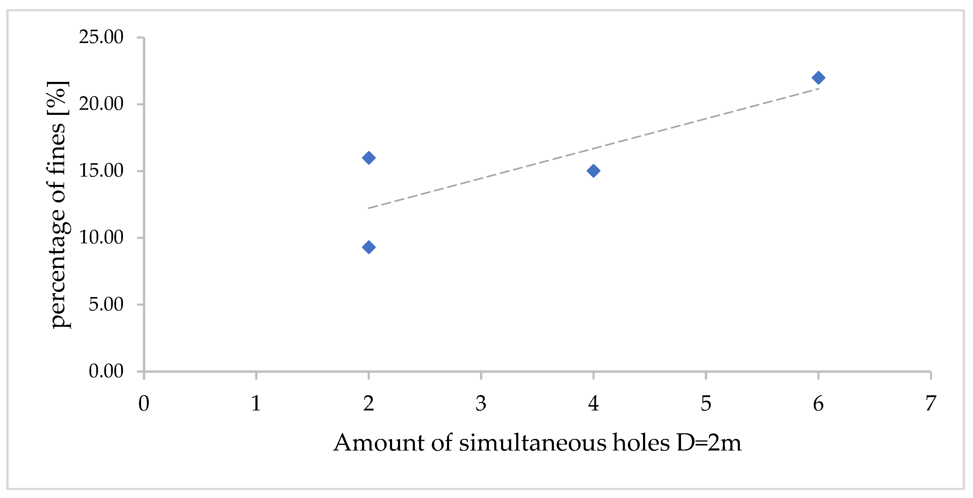
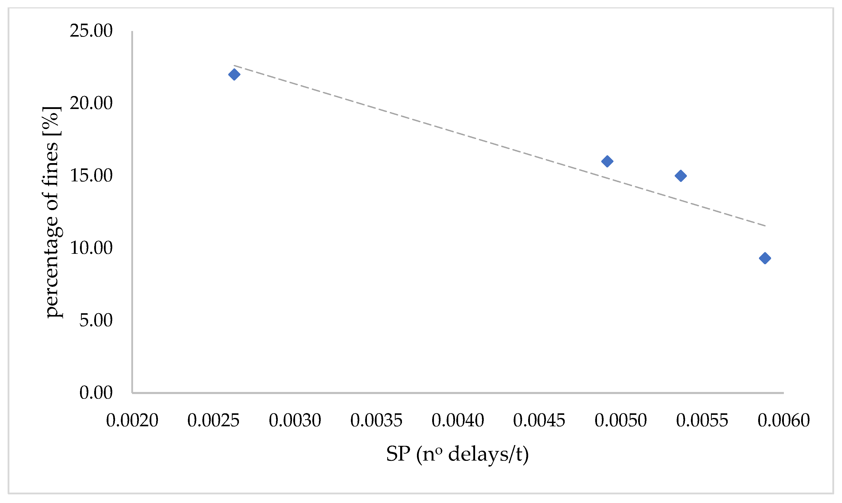
Percentage of fines in the muckpile f i n e s
[ % ]
The amount of material passing a mesh of 5 mm over the total amount of blasted material.
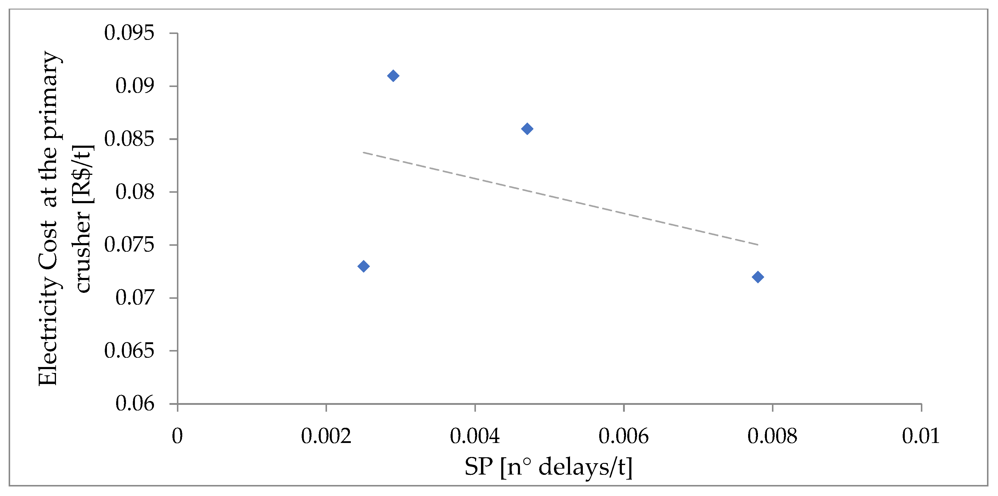
Electricity cost at the primary crusher C
[ R $ / t ]
The electricity consumption measured at the primary crusher via a direct electricity meter installed at the circuit feeding the engine, multiplied by the cost of kWh at the local electrical company.
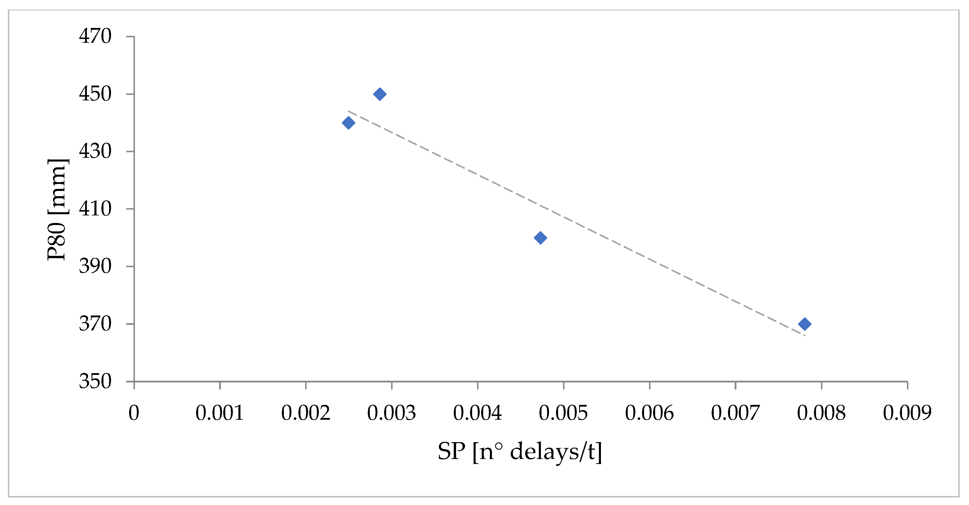
Passing size at 80% P 80
[mm]
The passing diameter for 80% of the mass of the fragments resulting from the blast, obtained via photographical analysis.
Specific primingSP
[n°delay/t]
The density of delays per unit of mass of blasted rock, quantifying the impact of timing on the blast plan.
Flyrock F y
[m]
In this research, flyrock is defined as the distance at which the fragment traveled furthest beyond the position of the muckpile. The trajectory and landing positions of the flyrock fragments were observed via high-speed video analysis of the blast and resulting movement of the muckpile.
Disclaimer/Publisher’s Note: The statements, opinions and data contained in all publications are solely those of the individual author(s) and contributor(s) and not of MDPI and/or the editor(s). MDPI and/or the editor(s) disclaim responsibility for any injury to people or property resulting from any ideas, methods, instructions or products referred to in the content.

