Abstract
The durability of reinforced concrete structures is a significant concern, with corrosion of reinforcement being a leading cause of reduced durability. To ensure accurate models, it is necessary to calibrate or validate them with direct measurements of the structures, specifically monitoring durability-related parameters. The heterogeneity of structures and the dispersion of the parameters considered in models make this calibration or validation essential. To enable the predictive maintenance of structures, it is essential to monitor the parameters related to their durability. This article presents the results of the monitoring of the temperature, corrosion potential, resistivity, and corrosion rate of two structural components, a beam and a tendon, for over 10 months. The obtained values were correlated with the climate to which they were exposed. The corrosion rate can be correlated with the influence of climate, enabling real-time estimation of section loss. This is a necessary step towards the digitization of structures or the development of digital twins that incorporate the effect of corrosion.
1. Introduction
One of the most significant challenges in reinforced concrete structures is durability. And the main cause is the reinforcement corrosion that plays a prominent role in limiting the durability [1,2,3], prompting the need for costly maintenance and repair [4,5,6]. The consequences of corrosion such as cracking or even spalling of the concrete cover, a loss of bonding, and a loss of cross-section, which can lead to brittle failure of the structures, are well known [7,8,9,10,11]. For structures with active reinforcement, it is crucial to monitor the onset of corrosion to prevent stress corrosion cracking and hydrogen embrittlement. These phenomena can cause brittle fracture of the structural components [7,12,13,14,15,16,17,18].
Due to complying with current regulations, reinforced concrete structures often fail to reach their intended service life due to various factors [19,20,21,22]. However, there is currently no tool available to accurately evaluate these structures, which makes proper maintenance difficult. Although regulations require predictive maintenance, the lack of proper assessment tools makes it challenging to implement in practice. Predictive maintenance can only be achieved through a continuous monitoring system and accurate measurement of durability parameters [23,24,25].
In the case of structures exposed to the environment, corrosion can occur due to carbonation, chloride exposure, or the presence of chloride additives in concrete. This corrosion can cause damage to the concrete, including cracking and spalling of the cover due to volume expansion, a reduction in the reinforcement cross-section due to the formation of rust products, and a loss of mechanical performance in the steel. Chloride-induced corrosion can be particularly hazardous in prestressed members due to the potential for pitting, which can lead to damage localization and localized failures. As the environmental attack becomes more aggressive over time, either due to chloride content or carbonation, the capacity of corroded reinforced concrete (RC) or prestressed concrete (PC) members gradually decreases. This can result in unexpected failures due to insufficient bending, shear, or anchorage resistance [9,11,21].
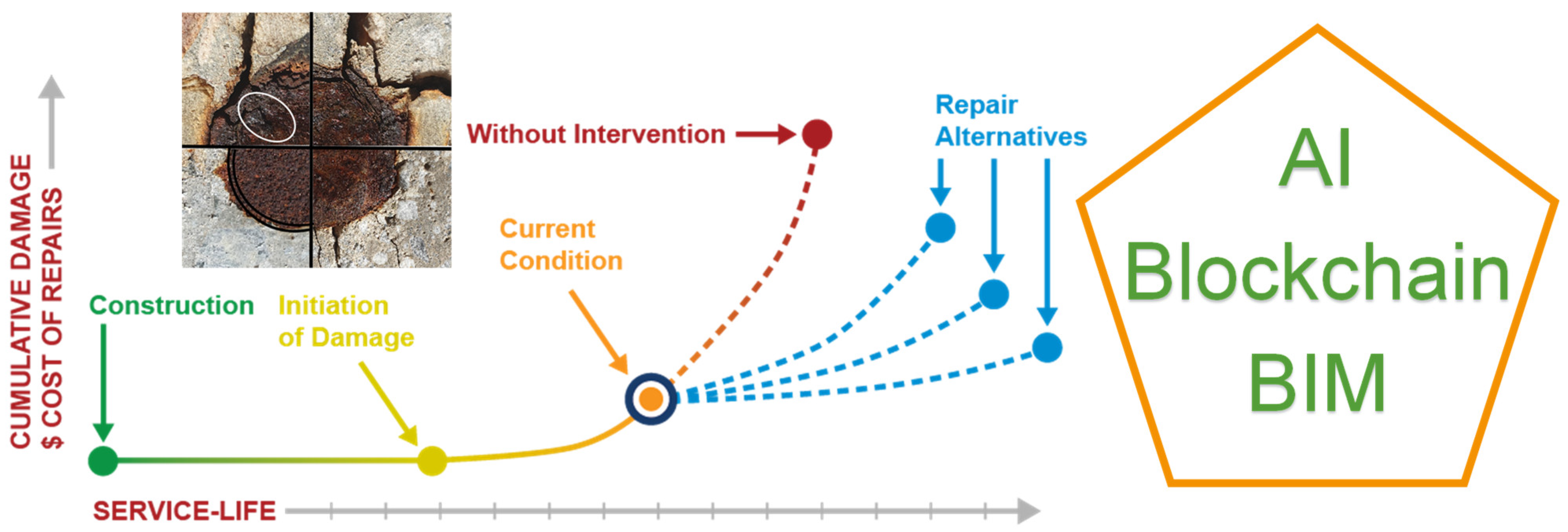
In order to ensure the durability of structures, it is essential to calibrate and update durability models in real-time with accurate and correctly measured information on the condition of the structure. Therefore, it is necessary to increase maintenance efforts and carry out predictive assessments to anticipate or detect corrosion of both active and passive reinforcement. The strategy for managing the structure’s life and planning maintenance involves integrating traditional inspection methods with new intelligent management tools. Additionally, real-time monitoring results should be incorporated and analysed to enable a shift from reactive repair to proactive diagnosis. This transition will influence the cost and scope of any necessary repairs [19,26,27,28]. In order to incorporate artificial intelligence tools in infrastructure maintenance, it is necessary to have precise measurement databases. These measurements can then be integrated into finite element models or digital twins to evaluate the structure’s real-time state (see Figure 1). This evaluation can be carried out either on new structures, existing structures, or repaired structures, which in turn would allow the durability and effectiveness of the repair itself to be assessed.
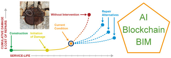
Figure 1.
Service life of structures.
Given the nature of corrosion itself, electrochemical techniques are the most suitable for measuring it. There are several studies and recommendations that define the methodology to be followed for a correct measurement [26,27,28,29]. The corrosion potential (Ecorr) measurement helps to identify the areas with corrosion probability. This is a qualitative parameter. Similarly, the electrical resistivity (ρ) enables the classification of areas according to moisture content, concrete porosity, and concrete microstructure [30,31]. Among the electrochemical techniques, only polarization resistance (Rp) measurements can quantify the corrosion rate (Icorr) [26]. Through Faraday’s law, the corrosion rate can be transformed into a loss of reinforcement cross-section. In order to calculate this accurately, it is necessary to have sufficient measurements over time. Consequently, the monitoring of structures represents the optimal method for acquiring precise knowledge of their state and carrying out analyses.
2. Methodology
In the field of research on reinforced concrete corrosion, potentiodynamic polarization tests are frequently employed as a rapid method for determining corrosion rates. These tests typically yield parameters such as corrosion potential and corrosion current density. In the case of polarization activation alone, the potentiostat-measured current density can be related to the corrosion current density by means of the Butler–Volmer equation. A linear polarisation resistance (LPR) was estimated by applying a polarisation value of ±20 mV relative to the open circuit potential (OCP) and a scanning rate of 0.166 mV/s. The corrosion rate was then calculated using the slope of the electric potential–cell current curve, minus the resistance drop, which was taken as Rp. The Stern–Geary equation was employed to ascertain the corrosion rate, icorr. In electrochemical impedance spectroscopy (EIS), an electric potential of varying frequency is applied to an electrochemical cell, and the resulting current’s complex field is measured. A Randles-type equivalent circuit was employed to simulate the system’s electrochemical response with a time constant [26,29,32].
In order to obtain accurate in-situ measurements of corrosion, it is essential to have proper control over the area being measured [26,33]. Additionally, it is necessary to estimate the ohmic drop during the measurements, as is done in laboratory measurements. The methodologies employed may be categorised into two distinct groups: those that necessitate direct contact with the reinforcement and those that do not.
The method of modulated current confinement utilises a guard ring during measurement [34]. To ensure accurate measurements, it is necessary to implement a system that controls the current to remain confined between the central counter electrode and the guard ring. This system comprises two reference electrodes known as ‘confinement controller electrodes’. Their potential difference is used to verify that the electrical field remains the same with and without current applied [33]. This verification must be monitored during the current application, which takes approximately 100 s to reach a steady-state condition. This operation is electronically complex. During this time, the two reference electrodes (confinement controllers) provide information to the galvanostat so that it can apply more or less current through the guard ring to confine the current applied beneath the counter electrode. This process is known as ‘modulated confinement’ because it requires monitoring both counters and actively varying the current applied through the guard ring during the measurement.
Non-contact methods are based on the Wenner method for resistivity measurement [31,35]. These methods have the advantage that it is not necessary to make a connection to the reinforcement; however, it is not possible to obtain the corrosion potential of the reinforcement. In this method, the current is applied by the external electrodes and the change in potential is measured by means of the two internal reference electrodes [36]. The external electrodes were small pieces of reinforcing steel, and the two internal reference electrodes were Ag/AgCl. Currents of 10–500 µA were applied. The difference in potential is measured by means of the two internal reference electrodes. The developments achieved in these studies make it possible to establish a correlation between the ohmic drop and the Rp values [36]. An electrical model has also been obtained to explain the behaviour of the system with respect to an external electric field [37].
This work presents a new measurement method called MONITORIZA, which accurately measures corrosion potential, resistivity, and temperature. The sensors used in this method are based on previous developments with over 25 years of research [23]. Measurements are scheduled every 2 h and the results are automatically analysed. The procedure is verified both in the laboratory and through in-situ measurements. It is legally registered by the National Scientific Research Council (CSIC). Currently, this system is being applied to various structures. This article presents the results obtained from the demonstrator located at IETcc-CSIC, which consists of two components: a beam and a tendon from a viaduct.
2.1. Components and Exposure Class
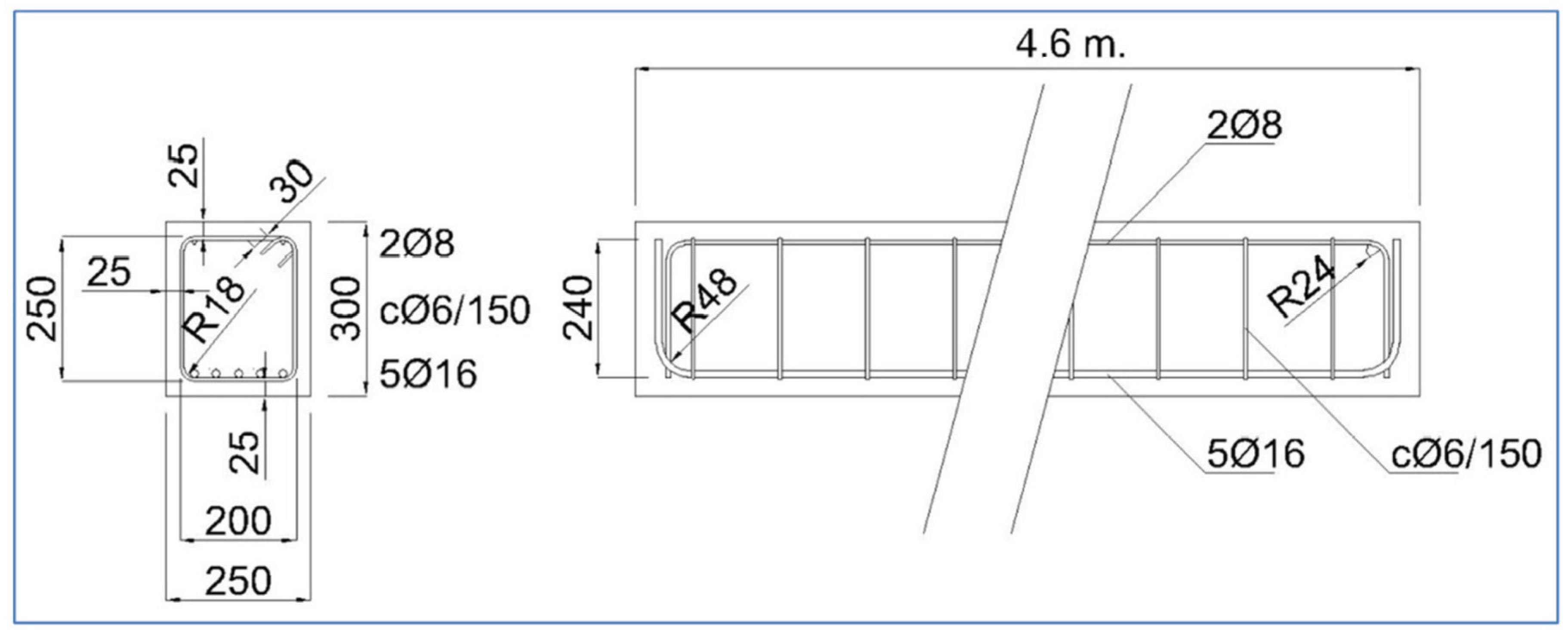
Two structural components exposed to the climate of Madrid, Spain were analysed (see Figure 2). The first component is a 460 × 30 × 25 cm beam, reinforced with 16 and 8 mm diameter passive reinforcement and 6 mm stirrup, and has a 25 mm concrete cover (see Figure 3). The second component is an external tendon from a train bridge that has been cut. It is a PVC tendon duct and has 8 high-strength steel tendons embedded in a grout. The sensors were placed on the surface of the beam. For the PVC duct, a hole was drilled to place the sensor in contact with the tendon grout. Although they are outside the scope of this article, tests were also carried out on steel tendon ducts. The sensors were connected to measuring equipment located 10 m away. The measuring equipment was placed in a connection cabinet that allowed for the corresponding measurements to be taken every two hours. The data were automatically analysed and added to a database, taking into account the date, position, and measured parameters in each case.

Figure 2.
Location: Madrid, Spain.
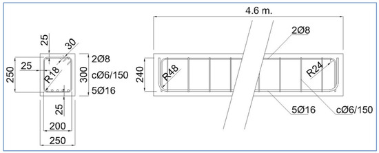
Figure 3.
Drawing of the beam. Drawing dimensions in mm.
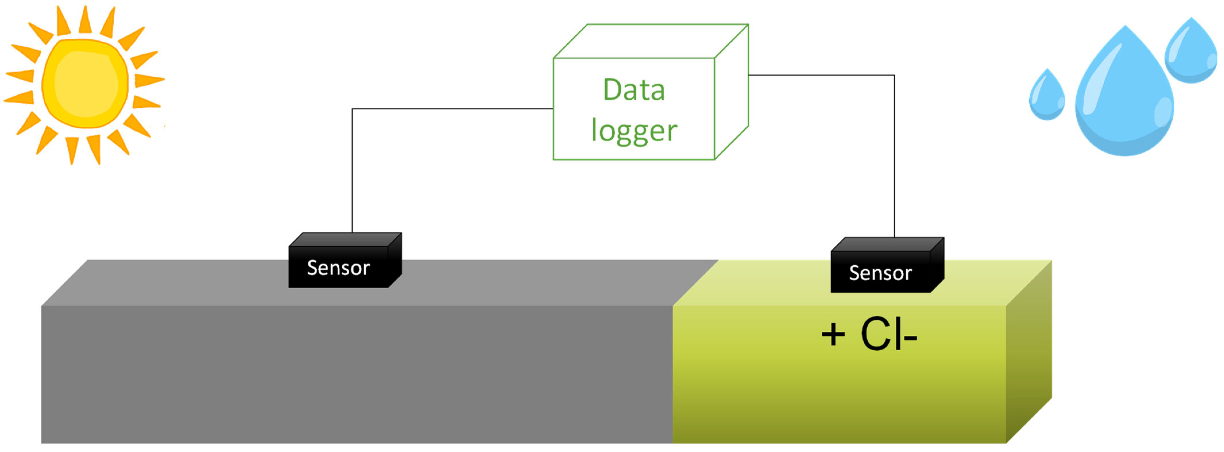
Two sensors were placed on the beam: one in a chloride-free area and the other in an area contaminated with chlorides through ponding and an electric field [38] (see Figure 4). As for the tendon, only one sensor was placed to observe its response to water presence [39]. As the duct seals this component, it is not exposed to weather conditions but only to temperature changes. For the tendon, water was introduced by manual addition at one end, with the element placed at a slight incline and the lower end covered to prevent water from escaping. Each sensor enables the simultaneous measurement of temperature, corrosion potential, resistivity, and corrosion rate. These parameters are measured automatically every 2 h in each sensor, and the data is analysed automatically. The results are available in real-time through an app.
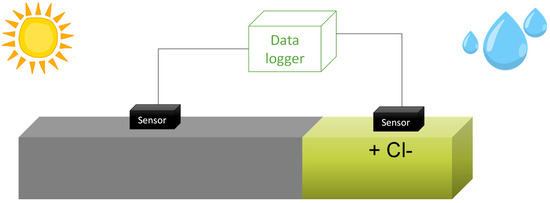
Figure 4.
Exposure of the beam to contaminants and the climate of Madrid. Sensors and monitoring system.
2.2. Climate
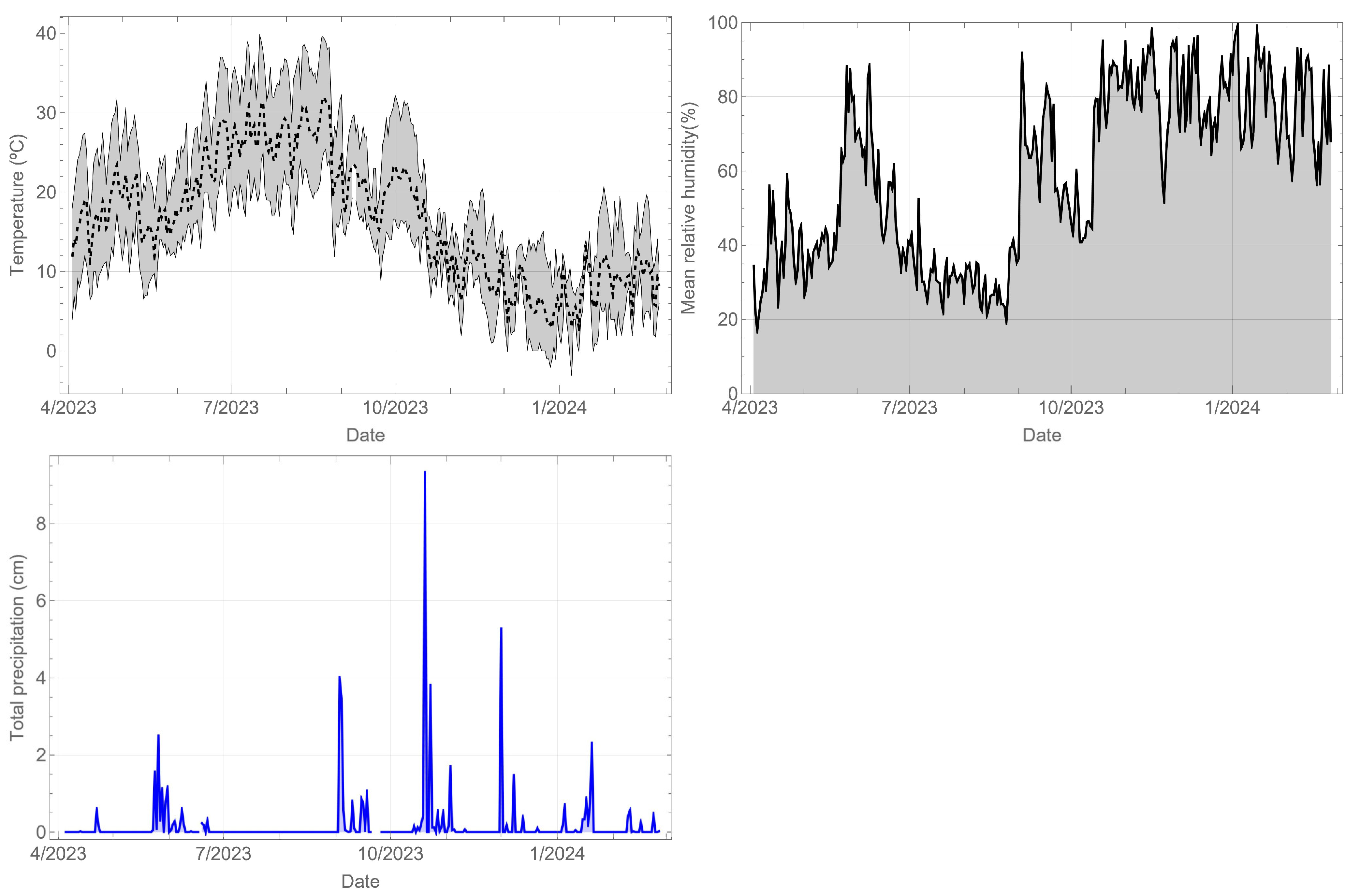
The climatological records of the station closest to the component site are shown below. Figure 5 shows the temperature (°C), relative humidity (%), and daily precipitation (cm). In the case of temperature, the daily mean, minimum, and maximum values are displayed. The recorded period spans almost a year, allowing for an evaluation of both daily and yearly cycles. The meteorological conditions exhibit a marked contrast between the summer season, characterised by temperatures reaching close to 40 °C, relative humidity of 20%, and no rainfall, and the winter season, with temperatures dropping below 10 °C, relative humidity of 80%, and rainfall.
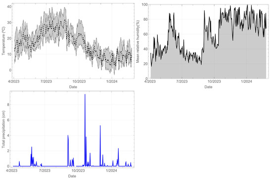
Figure 5.
Weather records for Madrid during the monitoring period.
3. Results
The parameters related to durability that were recorded by the sensors located on both the beam and the tendon are presented below. Each sensor recorded the corrosion rate, corrosion potential, resistivity, and temperature. The results for each sensor are displayed in a separate section.
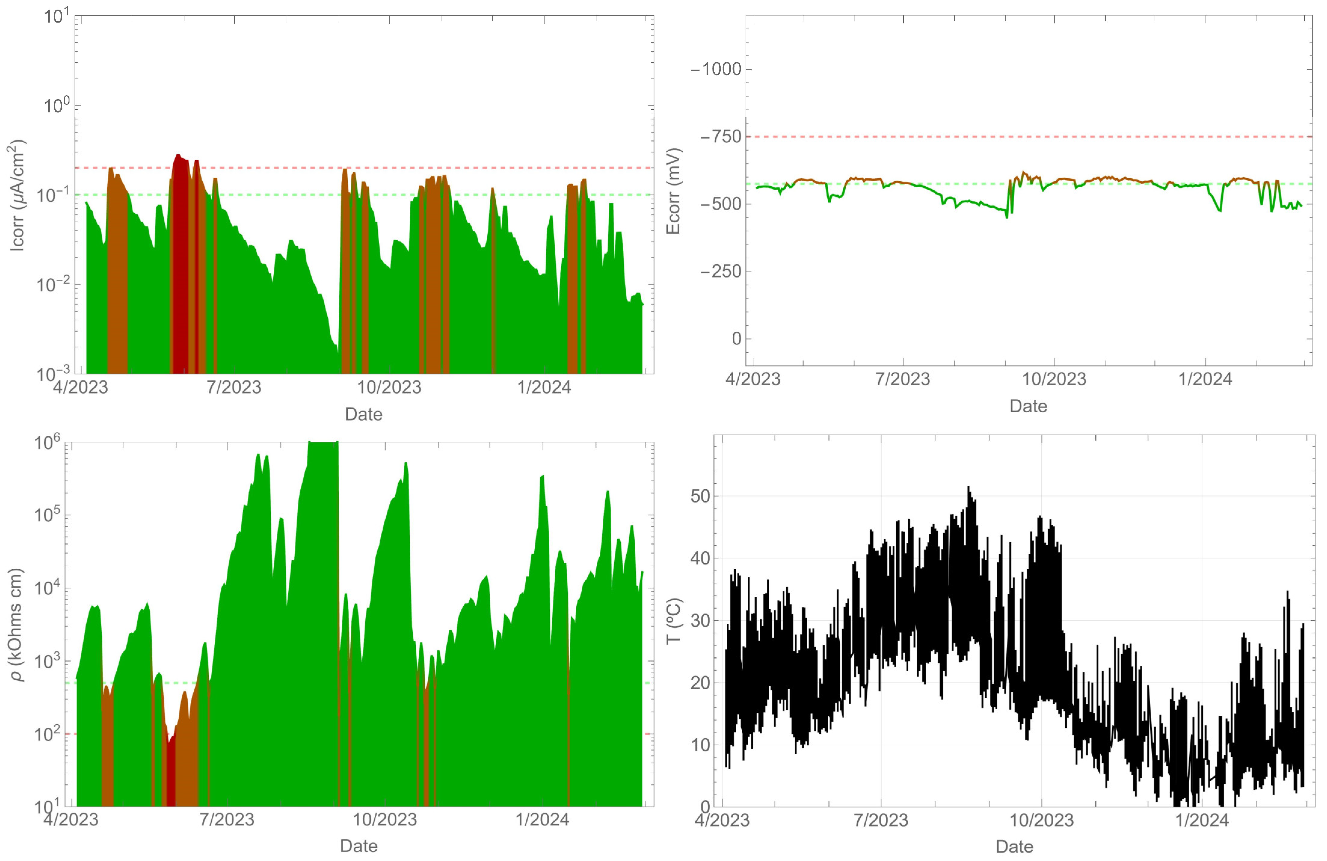
3.1. Corrosion Parameters of the Beam without Chlorides
As anticipated, the uncontaminated beam did not experience any corrosion throughout the monitoring period. The corrosion rate remained below 0.1 µA/cm2 (refer to Figure 6). Additionally, the corrosion potential was consistently maintained above −575 mVMnO2. The resistivity, especially in the summer, increased significantly by several orders of magnitude, while in the spring and autumn, it decreased to values close to 100 kΩ cm. A correlation between the corrosion rate and resistivity existed, with an evident decrease in the corrosion rate as the resistivity increased. Meanwhile, Figure 5 shows that the surface temperature of the beam can reach over 50 °C during the summer season, while the ambient temperature is 40 °C at that time.
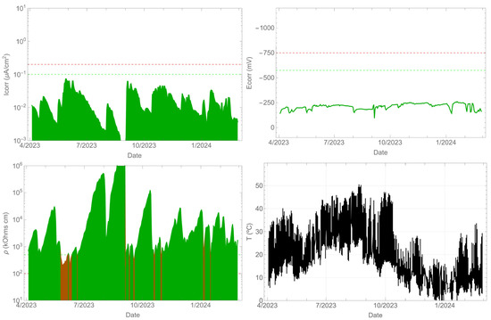
Figure 6.
Record of durability parameters. Contaminant-free beam side.
3.2. Corrosion Parameters of the Beam with Chlorides
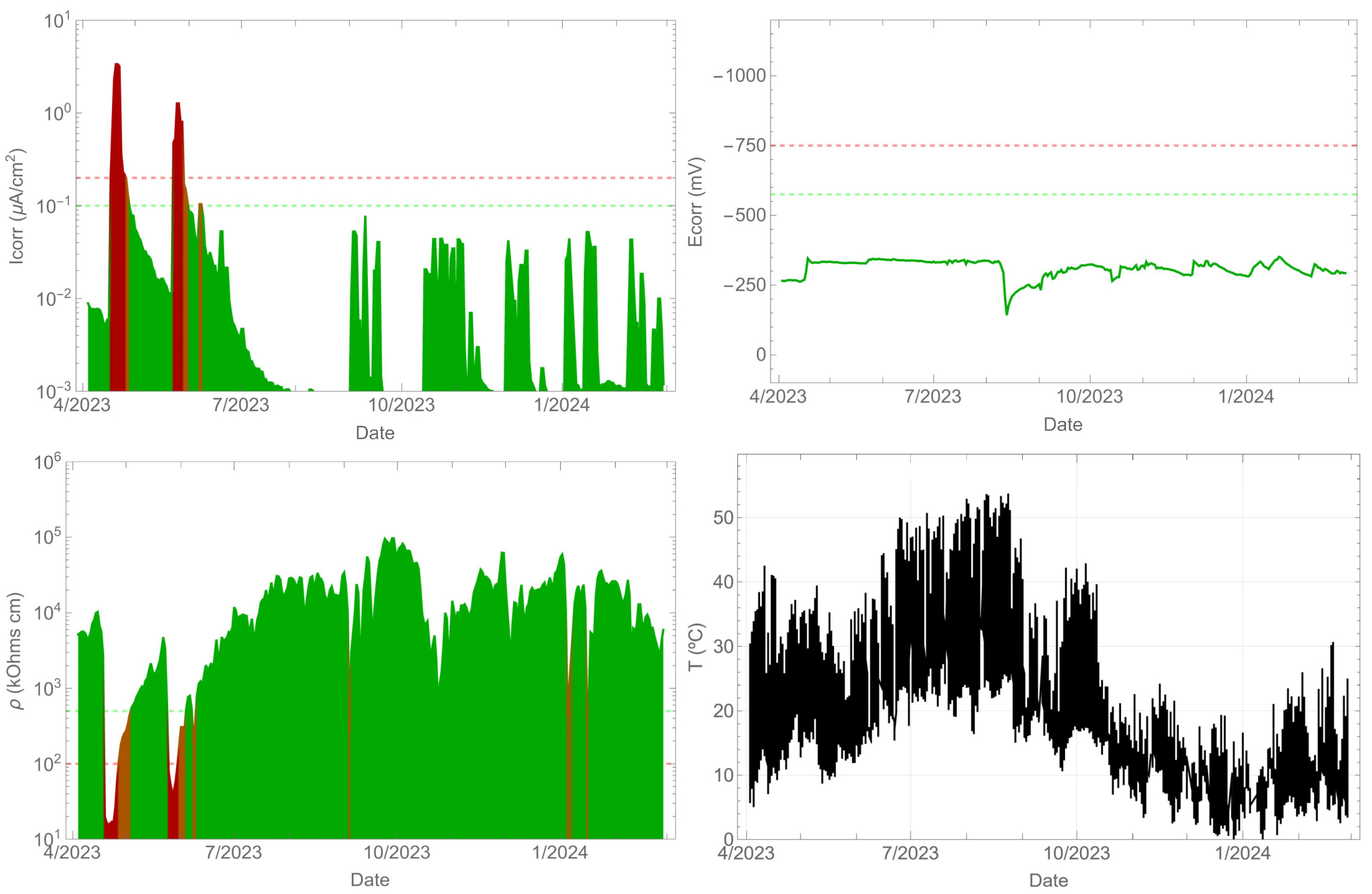
In contrast, the beam contaminated with chlorides exhibited corrosion (Figure 7), with corrosion rate values exceeding 0.1 µA/cm2. The corrosion potential remained between −575 and −700 mVMnO2. However, the corrosion rate values did not remain above 0.1 µA/cm2 throughout the entire time period. As in the previous case, a correlation between the corrosion rate and resistivity was observed. It is clear that as the resistivity increased, the corrosion rate decreased. The surface temperature of the beam is also shown, which is consistent with the previous measurement as it is the same element.
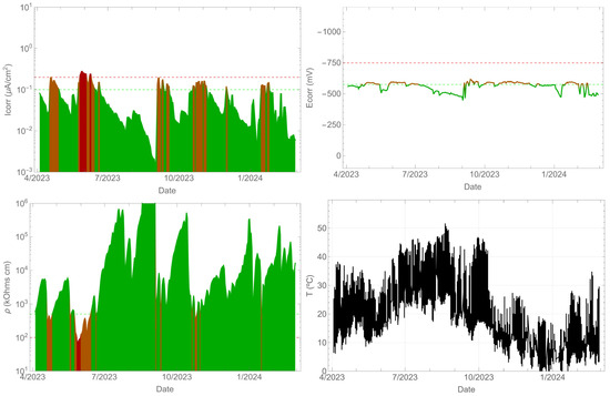
Figure 7.
Record of durability parameters. Beam side with contaminants.
3.3. Corrosion Parameters of the Tendon
In the case of the tendon (Figure 8), one side was sealed, and water was manually added on the other side. The corrosion rate response was influenced by the presence of water in the tendon, exceeding a value of 1 µA/cm2 temporarily. However, the corrosion potential was not sensitive to these changes. As in the previous cases, the resistivity varied with the presence of water and its variation was opposite to that of the corrosion rate. Furthermore, the temperature also reached values above 50 °C in the summer season. In this case, the objective was to detect the presence of corrosion in the steel when the insulation broke at the tendon and water ingress occurred. In any case, the presence of corrosion in high-strength steels should be avoided, as it can lead to brittle fractures due to stress corrosion cracking and hydrogen embrittlement.
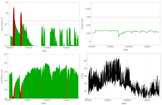
Figure 8.
Record of durability parameters. Tendon.
4. Discussion
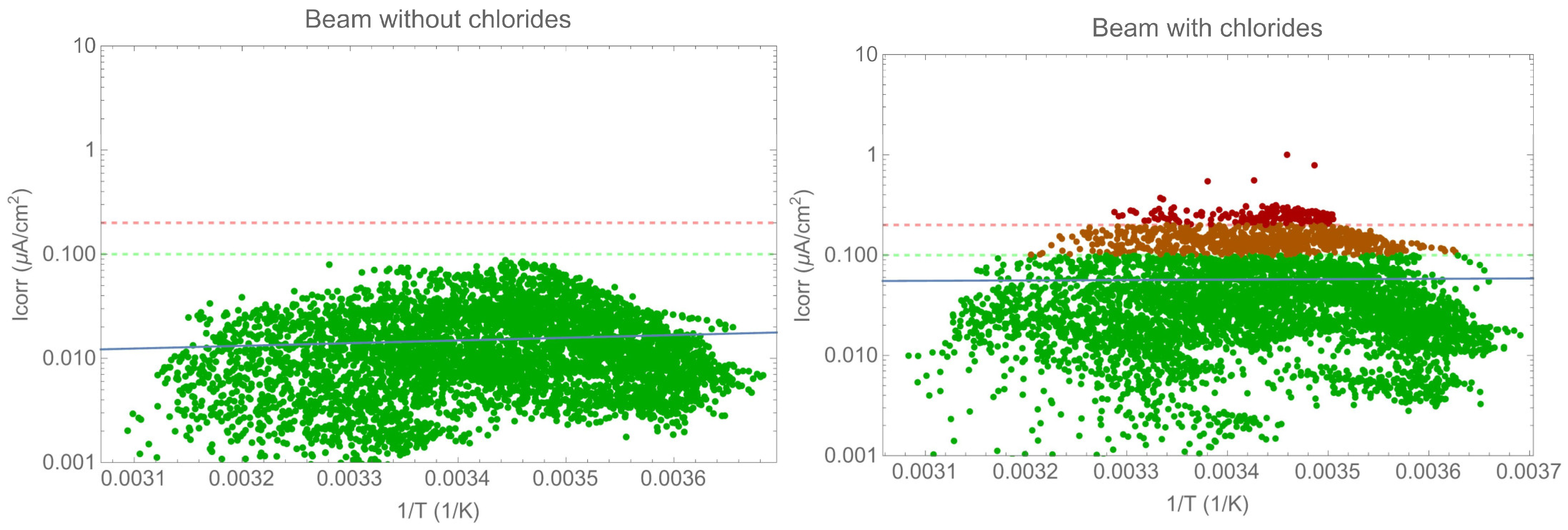
The following section analyses the corrosion rate evolution and the impact of environmental or exposure parameters. The analysis focused on the beam due to the type of exposure as the tendon is shielded from the environment. Figure 9 displays the corrosion rate evaluation as a function of the inverse temperature in an Arrhenius plot. It is important to note that there was no correlation between the two parameters. Other parameters have a greater influence than temperature alone, as will be discussed later. Previous results have shown a correlation between the two parameters when other conditions remain constant [23]. The results presented in the figures above demonstrate that the resistivity, and therefore water content, has a greater impact on the corrosion rate than temperature. To accurately determine the effect of temperature, it is essential to maintain constant values for all other parameters.

Figure 9.
Arrhenius-type plot of corrosion rate versus temperature.
Figure 10 illustrates the correlation between the corrosion rate and resistivity. According to Gulikers’ theoretical curve, the correlation between the corrosion current density, log(icorr), and concrete resistance, log(Rcon), can be approximated by an almost ideal linear relationship for a broad range of corrosion current densities. Assuming a fixed geometrical arrangement of anodic and cathodic sites on the steel surface, this linear relationship also applies to concrete resistivity, ρcon [31,35,40,41,42]. While resistivity does have an impact on the corrosion rate, it is important to note that this correlation is dependent on the specific system being measured, for instance, whether the system is active or passive. Therefore, it is not possible to establish a universal law for all cases. Additionally, it is important to note that there was a significant variation in the corrosion rate values for the same resistivity value. It is worth considering that the figures are presented on a double logarithmic scale, meaning that this variation represents differences of up to one order of magnitude.
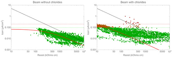
Figure 10.
Corrosion rate versus resistivity.
Further analysis, as illustrated in Figure 11, demonstrated the relationship between the corrosion potential and the corrosion rate in an Evans-type plot. The potential provides a qualitative indication of the risk of corrosion, as evidenced by previous studies [19,23,28,43,44], yet it is evident that there was a considerable degree of variation in the corrosion rate measurements. For a given value of corrosion potential, the steel can be either active or passive. In other words, in order to determine the real behaviour of the structure, it is necessary to carry out a correct measurement of the corrosion rate. With regard to the values of the thresholds for the corrosion potential, which are set out in standards and recommendations, it is important to exercise caution in their interpretation. There are studies that demonstrate that it is not possible to establish a universal criterion for these thresholds [45].
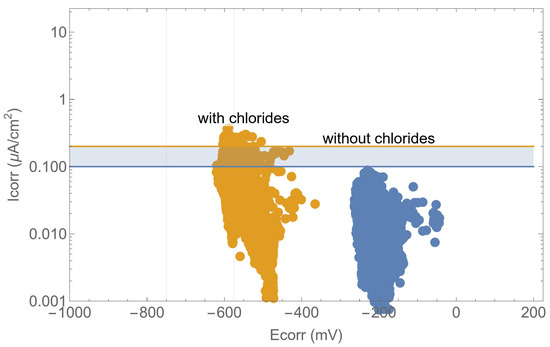
Figure 11.
Evans-type plot: corrosion rate versus corrosion potential.
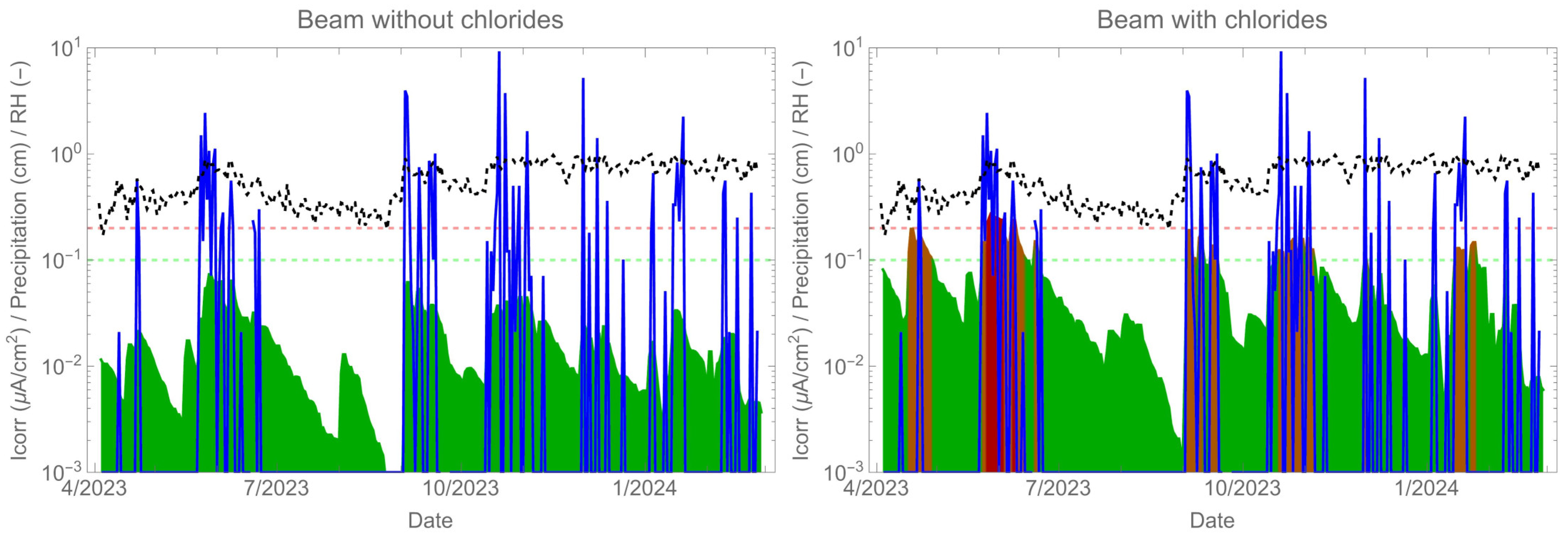
Figure 12 shows the corrosion rate results (green-red shaded curve) over a period of nearly 10 months along with the climate exposure data: relative humidity (black dotted curve) and rainfall (blue shaded curve). The data indicate that the corrosion rate and humidity exhibit similar behaviour, but it is the presence of rain that decisively activates corrosion. The corrosion rate measurement of the beam was almost instantaneous due to direct exposure to rainwater. The absorption of water was rapid, even over long periods of the structure’s life [46,47]. Therefore, if sufficient rainwater reaches the reinforcement and contains chloride, corrosion will occur. In cases of insufficient chloride concentration, a corrosion rate response is observed, but no depassivation occurs.
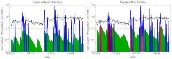
Figure 12.
Corrosion rate monitoring (green-red shaded curve) together with relative humidity (black dotted curve) and rainfall (blue shaded curve).
Corrosion rate monitoring enables the real-time estimation of reinforcement section loss by calculating the corrosion depth, Pcorr [23], which is related to the loss of radius through Faraday’s law (see Equation (1)). This allows for the calculation of section loss of reinforcement in a structure in real-time by integrating the corrosion rate curve. The acquisition of this parameter can be integrated into the mechanical behaviour model either on a punctual or continuous basis (digital twin), thereby enabling the automatic evaluation of the structure’s safety.
Here, is the pitting factor, MFe is the atomic mass of iron, n is the number of electrons for anodic reactions, d is the mass density of steel, and F is the Faraday’s constant.
Reinforced concrete structures may be affected by various corrosion mechanisms, including general corrosion, pitting, and stress corrosion cracking. Each mechanism induces a different mechanical behaviour, which can lead to macroscopic embrittlement [7,14,16,48]. While microscopic behaviour may be ductile in general and pitting corrosion, it may become brittle or quasi-brittle under stress corrosion cracking due to environment-mediated microstructural embrittlement. Hydrogen embrittlement (HE) is a phenomenon that can occur in conjunction with corrosion or stress corrosion and is considered a leading cause of structural steel cracking under stress. Studies on interstitial hydrogen in the iron network have shown that its primary effect is not due to the establishment of chemical bonds with iron atoms but rather the introduction of internal stresses that weaken the interactions between iron atoms, ultimately reducing fracture toughness [15,49,50,51,52,53]. Several studies have shown that fracture toughness (KIC) decreases when cracks form and propagate in aggressive, particularly corrosive environments. This decrease in fracture toughness means that the material fails at much smaller crack sizes under any given level of tensile stress. Brittle failure occurs with the onset of cleavage facets on a microscopic scale. The primary cause of this type of failure is hydrogen embrittlement. Based on experimental findings, it has been observed that hydrogen can reduce fracture toughness to approximately 60% of its value in an inert environment. There are two types of embrittlement: macroscopic brittleness induced by the notch effect, in which the steel remains ductile, and microscopic embrittlement due to hydrogen uptake in the iron lattice, resulting in the appearance of quasi-cleavage facets and a decrease in plastic deformation.
Figure 13 shows an example of a calculation for the depth of reinforcement corrosion and its corresponding linear fit. A linear fit has been used to estimate the corrosion evolution, which may vary depending on the environment and years of exposure. Pitting corrosion occurs in the presence of chlorides, and the pitting factor, α, must be considered. The pitting factor is the ratio between the maximum pitting size and the generalised corrosion. It allows for the calculation of the critical section loss in the reinforcement and takes values between 3 and 20 [10,39,54,55]. Assuming a pitting factor of 10 and that the recorded period is representative, the corrosion evolution can be estimated, and intervention on the beam can be planned. The estimated annual corrosion loss in the chloride-free zone of the beam is 0.20 µm, while in the chloride-contaminated zone, it is 7.6 µm. Therefore, if the durability limit state is set at 50 µm [56], the chloride-contaminated zone would reach this limit state in approximately 6.6 years, whereas the chloride-free part has a life of over 200 years.
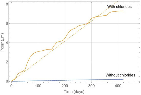
Figure 13.
Corrosion depth in the reinforcement versus time in days.
This approach allows for the combination of information regarding durability parameters and the mechanical behaviour of structural components. In certain cases, such as with high-strength active steels, corrosion initiation is not permitted due to the high risk of stress corrosion cracking or hydrogen embrittlement. As demonstrated in the example with the tendon, the proposed method allows for the clear detection of the onset of corrosion. In the case of reinforcements, corrosion can lead to local failures. The monitoring system enables the detection of the onset of corrosion, allowing for the protection or repair of the structure before visible deterioration occurs. For instance, corrosion inhibitors can be used, which can be evaluated in real-time by the system itself to determine their effectiveness.
5. Conclusions
The MONITORIZA method for measuring the corrosion rate was employed to demonstrate the evolution of durability parameters for two components: a beam and a tendon. This method allowed us to correlate the variation in these parameters with the presence or absence of contaminants (chlorides) and, importantly, the influence of the climate. Our study was conducted in Madrid, Spain.
It is necessary to employ direct measurement in order to estimate the corrosion rate, as the corrosion potential and resistivity alone are unable to provide this information. While the corrosion potential can indicate the likelihood of corrosion on reinforcement, the decisive factor for corrosion to occur is the presence of water and depassivating agents. On the other hand, resistivity is precisely related to moisture content. However, there is a large dispersion depending on the condition of the reinforcement. Therefore, it is necessary to measure the corrosion rate directly on the reinforcement itself.
The methodology presented in this work will allow direct information to be obtained on the durability of structures exposed to different environments. It is especially relevant to be able to characterise those structures that are in more aggressive environments, such as those exposed to tidal races, but also critical structural components, such as pre- or post-tensioned steels in which any type of depassivation or onset of corrosion must be avoided. This is the first requisite for the prediction of the future behaviour of reinforced concrete structures and even for the adaptation of regulations in accordance with these results. Conversely, the utilisation of novel steels or cements can modify the durable behaviour of structures, without consideration of the impact of repair on the remainder of the structure. For these reasons, direct control over the structures themselves represents an advance in knowledge that can be approached with the use of new tools for data analysis and interpretation.
The digitization of structures and the implementation of a predictive maintenance plan both require monitoring. As demonstrated, it is feasible to estimate real-time section loss for both active and passive reinforcement. This enables the feeding of durability models and digital twins, which can assess the structure’s safety. If repairs are made to the structure, this system also allows for the evaluation of the repair’s durability.
Author Contributions
Conceptualization, N.R. and J.S.; methodology, A.S. and J.E.T.; software, J.S.; validation, all authors; formal analysis, all authors; investigation, N.R.; resources, J.E.T.; data curation, A.S.; writing—original draft preparation, all authors; writing—review and editing, all authors; visualization, all authors; supervision, J.S. All authors have read and agreed to the published version of the manuscript.
Funding
This research received no external funding.
Institutional Review Board Statement
Not applicable.
Informed Consent Statement
Not applicable.
Data Availability Statement
The raw data supporting the conclusions of this article will be made available by the authors on request.
Conflicts of Interest
The authors declare no conflicts of interest.
References
- Xia, J.; Li, T.; Fang, J.-X.; Jin, W. Numerical Simulation of Steel Corrosion in Chloride Contaminated Concrete. Constr. Build. Mater. 2019, 228, 116745. [Google Scholar] [CrossRef]
- Hou, B.; Li, X.; Ma, X.; Du, C.; Zhang, D.; Zheng, M.; Xu, W.; Lu, D.; Ma, F. The Cost of Corrosion in China. NPJ Mater. Degrad. 2017, 1, 4. [Google Scholar] [CrossRef]
- Schueremans, L.; Van Gemert, D.; Giessler, S. Chloride Penetration in RC-Structures in Marine Environment—Long Term Assessment of a Preventive Hydrophobic Treatment. Constr. Build. Mater. 2007, 21, 1238–1249. [Google Scholar] [CrossRef]
- Val, D.V.; Stewart, M.G. Life-Cycle Cost Analysis of Reinforced Concrete Structures in Marine Environments. Struct. Saf. 2003, 25, 343–362. [Google Scholar] [CrossRef]
- Zhu, W.; François, R.; Fang, Q.; Zhang, D. Influence of Long-Term Chloride Diffusion in Concrete and the Resulting Corrosion of Reinforcement on the Serviceability of RC Beams. Cem. Concr. Compos. 2016, 71, 144–152. [Google Scholar] [CrossRef]
- Wei, J.; Wang, C.-G.; Wei, X.; Mu, X.; He, X.-Y.; Dong, J.-H.; Ke, W. Corrosion Evolution of Steel Reinforced Concrete under Simulated Tidal and Immersion Zones of Marine Environment. Acta Metall. Sin. (Engl. Lett.) 2019, 32, 900–912. [Google Scholar] [CrossRef]
- Sanchez, J.; Fullea, J.; Andrade, C. Corrosion-Induced Brittle Failure in Reinforcing Steel. Theor. Appl. Fract. Mech. 2017, 92, 229–232. [Google Scholar] [CrossRef]
- Sanchez, J.; Fullea, J.; Andrade, C. Fracto-Surface Mobility Mechanism in High-Strength Steel Wires. Eng. Fract. Mech. 2017, 186, 410–422. [Google Scholar] [CrossRef]
- Franceschini, L.; Vecchi, F.; Tondolo, F.; Belletti, B.; Sánchez Montero, J. Mechanical Behaviour of Corroded Strands under Chloride Attack: A New Constitutive Law. Constr. Build. Mater. 2022, 316, 125872. [Google Scholar] [CrossRef]
- Vecchi, F.; Franceschini, L.; Tondolo, F.; Belletti, B.; Sánchez Montero, J.; Minetola, P. Corrosion Morphology of Prestressing Steel Strands in Naturally Corroded PC Beams. Constr. Build. Mater. 2021, 296, 123720. [Google Scholar] [CrossRef]
- Franceschini, L.; Vecchi, F.; Tondolo, F.; Belletti, B.; Montero, J.S.; Minetola, P. Proceedings of the Variability in Section Loss and Maximum Pit Depth of Corroded Prestressing Wires BT—Proceedings of the 1st Conference of the European Association on Quality Control of Bridges and Structures, Espoo, Finland, 25–27 January 2023; Pellegrino, C., Faleschini, F., Zanini, M.A., Matos, J.C., Casas, J.R., Strauss, A., Eds.; Springer International Publishing: Cham, Switzerland, 2022; pp. 491–498. [Google Scholar]
- Parkins, R.N.; Elices, M.; Sanchez-Galvez, V.; Caballero, L. Environment Sensitive Cracking of Pre-Stressing Steels. Corros. Sci. 1982, 22, 379–405. [Google Scholar] [CrossRef]
- Franceschini, L.; Belletti, B.; Tondolo, F.; Sanchez Montero, J. A Simplified Stress–Strain Relationship for the Mechanical Behavior of Corroded Prestressing Strands: The SCPS-Model. Struct. Concr. 2023, 24, 189–210. [Google Scholar] [CrossRef]
- Sanchez, J.; Fullea, J.; Andrade, C. Stress Corrosion Cracking of High Strength Steels. In 1st International RILEM PhD Student Workshop on Modelling the Durability of Reinforced Concrete; Gulikers, J., Andrade, C., Eds.; National Repository Library: Madrid, India, 2007. [Google Scholar]
- Sanchez, J.; Fullea, J.; Andrade, C.; De Andres, P.L. Hydrogen in α-Iron: Stress and Diffusion. Phys. Rev. B Condens. Matter Mater. Phys. 2008, 78, 014113. [Google Scholar] [CrossRef]
- Sanchez, J.; Fullea, J.; Andrade, C.; Alonso, C. Stress Corrosion Cracking Mechanism of Prestressing Steels in Bicarbonate Solutions. Corros. Sci. 2007, 49, 4069–4080. [Google Scholar] [CrossRef]
- Sanchez, J.; Fullea, J.; Andrade, C. Fracture Toughness Variation Induced by Stress Corrosion Cracking of Prestressing Steels. Mater. Corros. 2008, 59, 139–143. [Google Scholar] [CrossRef]
- Sanchez, J.; Andrade, C.; Fullea, J. Reasons for Crack Arrest in Stress Corrosion Cracking Tests—Crack Propagation Rate in High-Strength Steels. Corrosion 2009, 65, 368–375. [Google Scholar] [CrossRef]
- Torres Martín, J.E.; Rebolledo Ramos, N.; Chinchón-Payá, S.; Helices Arcila, I.; Silva Toledo, A.; Sánchez Montero, J.; Llorente Sanjuán, M.; Agulló Soto, S.; Otero García, F.; de Haan, L. Durability of a Reinforced Concrete Structure Exposed to Marine Environment at the Málaga Dock. Case Stud. Constr. Mater. 2022, 17, e01582. [Google Scholar] [CrossRef]
- Gómez, P.S.; Montero, J.S.; Martín, J.E.T.; Chinchón-Payá, S.; Ramos, N.R. Decreased Useful Life in Air Chamber Reinforced Concrete Elements under Sanitary Floors by Carbonation Corrosion. Case Stud. Constr. Mater. 2023, 19, e02390. [Google Scholar] [CrossRef]
- Vecchi, F.; Belletti, B.; Franceschini, L.; Andrade, C.; Rodriguez, J.; Montero, S.J. Flexural Tests on Prestressed Beams Exposed to Natural Chloride Action. In Fib CACRCS DAYS 2020; FIB: Los Santos, Panama, 2021; pp. 205–212. [Google Scholar]
- Belletti, B.; Rodríguez, J.; Andrade, C.; Franceschini, L.; Sánchez Montero, J.; Vecchi, F. Experimental Tests on Shear Capacity of Naturally Corroded Prestressed Beams. Struct. Concr. 2020, 21, 1777–1793. [Google Scholar] [CrossRef]
- Rebolledo, N.; Torres, J.; Chinchón-Payá, S.; Sánchez, J.; de Gregorio, S.; Ordóñez, M.; López, I. Monitoring in a Reinforced Concrete Structure for Storing Low and Intermediate Level Radioactive Waste. Lessons Learnt after 25 Years. Nucl. Eng. Technol. 2023, 55, 1199–1209. [Google Scholar] [CrossRef]
- Sanchez, J.; Andrade, C.; Fullea, J. Hydrothermal Monitoring Using Embedded Sensors of the Actual Roof System of the Prado Museum. Constr. Build. Mater. 2010, 24, 2579–2589. [Google Scholar] [CrossRef]
- Andrade, C.; Martinez, I.; Castellote, M.; Zuloaga, P. Some Principles of Service Life Calculation of Reinforcements and in Situ Corrosion Monitoring by Sensors in the Radioactive Waste Containers of El Cabril Disposal (Spain). J. Nucl. Mater. 2006, 358, 82–95. [Google Scholar] [CrossRef]
- Vennesland, Ø.; Raupach, M.; Andrade, C. Recommendation of Rilem TC 154-EMC: “Electrochemical Techniques for Measuring Corrosion in Concrete”—Measurements with Embedded Probes. Mater. Struct. 2007, 40, 745–758. [Google Scholar] [CrossRef]
- Polder, R.; Andrade, C.; Elsener, B.; Vennesland, Ø.; Gulikers, J.; Weidert, R.; Raupach, M. Test Methods for on Site Measurement of Resistivity of Concrete. Mater. Struct. 2000, 33, 603–611. [Google Scholar] [CrossRef]
- Angst, U.; Moro, F.; Geiker, M.; Kessler, S.; Beushausen, H.; Andrade, C.; Lahdensivu, J.; Köliö, A.; Imamoto, K.; von Greve-Dierfeld, S.; et al. Corrosion of Steel in Carbonated Concrete: Mechanisms, Practical Experience, and Research Priorities—A Critical Review by RILEM TC 281-CCC. RILEM Tech. Lett. 2020, 5, 85–100. [Google Scholar] [CrossRef]
- Garcia, E.; Torres, J.; Rebolledo, N.; Arrabal, R.; Sanchez, J. Corrosion of Steel Rebars in Anoxic Environments. Part I: Electrochemical Measurements. Materials 2021, 14, 2491. [Google Scholar] [CrossRef]
- Warkus, J.; Raupach, M.; Gulikers, J. Numerical Modelling of Corrosion—Theoretical Backgrounds. Mater. Corros. 2006, 57, 614–617. [Google Scholar] [CrossRef]
- Sanchez, J.; Andrade, C.; Torres, J.; Rebolledo, N.; Fullea, J. Determination of Reinforced Concrete Durability with On-Site Resistivity Measurements. Mater. Struct. 2017, 50, 41. [Google Scholar] [CrossRef]
- Garcia, E.; Torres, J.; Rebolledo, N.; Arrabal, R.; Sanchez, J. Corrosion of Steel Rebars in Anoxic Environments. Part II: Pit Growth Rate and Mechanical Strength. Materials 2021, 14, 2547. [Google Scholar] [CrossRef]
- Andrade, C.; Sanchez, J.; Fullea, J.; Rebolledo, N.; Tavares, F. On-Site Corrosion Rate Measurements: 3D Simulation and Representative Values. Mater. Corros. 2012, 63, 1154–1164. [Google Scholar] [CrossRef]
- Feliu, S.; Gonzalez, J.A.; Andrade, C.; Rzmaribona, I. Errors Introduced by the Guard Ring Device in the On-Site Measurement of Rebar Corrosion Rates; Page, C.L., Treadaway, K.W.J., Bamforth, P.B., Eds.; CICC Publications: Kerala, India, 1990; ISBN 1-85166-487-4. [Google Scholar]
- Garzon, A.J.; Sanchez, J.; Andrade, C.; Rebolledo, N.; Menéndez, E.; Fullea, J. Modification of Four Point Method to Measure the Concrete Electrical Resistivity in Presence of Reinforcing Bars. Cem. Concr. Compos. 2014, 53, 249–257. [Google Scholar] [CrossRef]
- Keddam, M.; Nóvoa, X.R.; Puga, B.; Vivier, V. Impedance Based Method for Non-Contact Determination of the Corrosion Rate in Buried Metallic Structures. Eur. J. Environ. Civil. Eng. 2011, 15, 1097–1103. [Google Scholar] [CrossRef]
- Andrade, C.; Sanchez, J.; Martinez, I.; Rebolledo, N. Analogue Circuit of the Inductive Polarization Resistance. Electrochim. Acta 2011, 56, 1874–1880. [Google Scholar] [CrossRef]
- Caneda-Martínez, L.; Frías, M.; Medina, C.; de Rojas, M.I.S.; Rebolledo, N.; Sánchez, J. Evaluation of Chloride Transport in Blended Cement Mortars Containing Coal Mining Waste. Constr. Build. Mater. 2018, 190, 200–210. [Google Scholar] [CrossRef]
- Morales, J.A.; Torres, J.; Rebolledo, N.; Sánchez, J. Experimental and Statistical Analysis of the Corrosion in Tendons in Contact With Water. Front. Mater. 2019, 6, 167. [Google Scholar] [CrossRef]
- Hornbostel, K.; Larsen, C.K.; Geiker, M.R. Relationship between Concrete Resistivity and Corrosion Rate—A Literature Review. Cem. Concr. Compos. 2013, 39, 60–72. [Google Scholar] [CrossRef]
- Garzon, A.J.; Andrade, C.; Rebolledo, N.; Fullea, J.; Sanchez, J.; Menéndez, E. Shape Factors of Four Point Resistivity Method in Presence of Rebars. In Proceedings of the Concrete Repair, Rehabilitation and Retrofitting III—Proceedings of the 3rd International Conference on Concrete Repair, Rehabilitation and Retrofitting, ICCRRR 2012, Cape Town, South Africa, 3–5 September 2012; pp. 695–700. [Google Scholar]
- Gulikers, J. Theoretical Considerations on the Supposed Linear Relationship between Concrete Resistivity and Corrosion Rate of Steel Reinforcement. Mater. Corros. 2005, 56, 393–403. [Google Scholar] [CrossRef]
- Keßler, S.; Fischer, J.; Straub, D.; Gehlen, C. Updating of Service-Life Prediction of Reinforced Concrete Structures with Potential Mapping. Cem. Concr. Compos. 2014, 47, 47–52. [Google Scholar] [CrossRef]
- Keßler, S. Probabilistic Corrosion Condition Assessment of a Tunnel Structure. Struct. Concr. 2020, 21, 1345–1355. [Google Scholar] [CrossRef]
- De Domenico, D.; Messina, D.; Recupero, A. Seismic Vulnerability Assessment of Reinforced Concrete Bridge Piers with Corroded Bars. Struct. Concr. 2023, 24, 56–83. [Google Scholar] [CrossRef]
- Villagrán Zaccardi, Y.A.; Alderete, N.M.; De Belie, N. Improved Model for Capillary Absorption in Cementitious Materials: Progress over the Fourth Root of Time. Cem. Concr. Res. 2017, 100, 153–165. [Google Scholar] [CrossRef]
- Alderete, N.M.; Villagrán Zaccardi, Y.A.; De Belie, N. Mechanism of Long-Term Capillary Water Uptake in Cementitious Materials. Cem. Concr. Compos. 2020, 106, 103448. [Google Scholar] [CrossRef]
- Sanchez, J.; Lee, S.F.; Martin-Rengel, M.A.; Fullea, J.; Andrade, C.; Ruiz-Hervías, J. Measurement of Hydrogen and Embrittlement of High Strength Steels. Eng. Fail. Anal. 2016, 59, 467–477. [Google Scholar] [CrossRef]
- Sanchez, J.; Ridruejo, A.; de Andres, P.L. Diffusion and Trapping of Hydrogen in Carbon Steel at Different Temperatures. Theor. Appl. Fract. Mech. 2020, 110, 102803. [Google Scholar] [CrossRef]
- Castedo, A.; Sanchez, J.; Fullea, J.; Andrade, C.; de Andres, P.L. Hydrogen Induced Changes in Structural Properties of Iron: Ab Initio Calculations; Springer Netherlands: Dordrecht, The Netherlands, 2012; Volume 3, ISBN 9789400727021. [Google Scholar]
- Sanchez, J.; Fullea, J.; Andrade, M.C.; De Andres, P.L. Ab Initio Molecular Dynamics Simulation of Hydrogen Diffusion in α-Iron. Phys. Rev. B Condens. Matter Mater. Phys. 2010, 81, 132102. [Google Scholar] [CrossRef]
- de Andres, P.L.; Sanchez, J.; Ridruejo, A. Hydrogen in α-Iron: Role of Phonons in the Diffusion of Interstitials at High Temperature. Sci. Rep. 2019, 9, 12127. [Google Scholar] [CrossRef]
- Castedo, A.; Sanchez, J.; Fullea, J.; Andrade, M.C.; De Andres, P.L. Ab Initio Study of the Cubic-to-Hexagonal Phase Transition Promoted by Interstitial Hydrogen in Iron. Phys. Rev. B Condens. Matter Mater. Phys. 2011, 84, 094101. [Google Scholar] [CrossRef]
- Turnbull, A.; McCartney, L.N.; Zhou, S. Modelling of the Evolution of Stress Corrosion Cracks from Corrosion Pits. Scr. Mater. 2006, 54, 575–578. [Google Scholar] [CrossRef]
- Franceschini, L.; Belletti, B.; Tondolo, F.; Sanchez, J. Study on the Probability Distribution of Pitting for Naturally Corroded Prestressing Strands Accounting for Surface Defects. Buildings 2022, 12, 1732. [Google Scholar] [CrossRef]
- Geiker, M.R.; Hendriks, M.A.N.; Elsener, B. Durability-Based Design: The European Perspective. Sustain. Resilient Infrastruct. 2023, 8, 169–184. [Google Scholar] [CrossRef]


Disclaimer/Publisher’s Note: The statements, opinions and data contained in all publications are solely those of the individual author(s) and contributor(s) and not of MDPI and/or the editor(s). MDPI and/or the editor(s) disclaim responsibility for any injury to people or property resulting from any ideas, methods, instructions or products referred to in the content. |
© 2024 by the authors. Licensee MDPI, Basel, Switzerland. This article is an open access article distributed under the terms and conditions of the Creative Commons Attribution (CC BY) license (https://creativecommons.org/licenses/by/4.0/).