Abstract
Moment-resisting frames (MRFs) and eccentrically braced frames (EBFs) can be effectively combined in multi-story steel buildings. In fact, MRFs provide redundancy and ductility, while EBFs provide initial and post-yield stiffness with high energy dissipation capacity. In addition, if detachable links are designed as dissipative fuses, it is possible to activate their almost contemporary yielding and prevent the collapse of structures during severe earthquakes, ensuring easy repair and rehabilitation measures. The seismic responses of dual frames with MRFs and EBFs are investigated by means of pushover analyses. Different buildings were designed, varying the number of floors (two, four, and eight stories), the number of MRF spans (zero, one, and two), and the length of the short links (0.8 Mp/Vp and 1.6 Mp/Vp). The obtained results confirmed the superior behavior of dual frames with respect to simple EBFs. In addition, it was observed that the frames with the shorter links exhibited higher resistance and rigidity but smaller overall displacement capacity because of the anticipated failure of the links.
1. Introduction
Steel structures are largely selected for use in seismic areas [1,2] since they can exhibit high levels of ductility and dissipation capacity [3]. Among the large variety of steel systems, eccentrically braced systems (EBFs) are one of the most ductile. EBFs are thought to concentrate the seismic damage mainly into the “link” element. This feature may allow for replacing the damaged links with new ones after seismic damage. Unfortunately, the yielding of links is associated with a permanent residual drift in the structure which can make impossible to replace the damaged links. To overcome such limitations, recent studies investigated the possibility of enforcing a re-centering capability in EBFs by simply adding some moment resisting frames (MRFs) in parallel to the EBFs, thus transforming the EBFs in a dual structural system (i.e., the combination of MRFs and EBFs) [4,5].
Sina and Topkaya (2017) [6] present a review of the state of the art of the design of eccentrically braced frames, discussing the most significant studies in that field. Among them, Bosco et al. (2014) [7] highlighted that the upper bound value of the behavior factor for eccentrically braced frames in the Eurocode 8 is excessive (i.e., 6) and proposed the use of a lower value (i.e., 5). In 2017 Bosco et al. [8,9] conducted a series of incremental dynamic analyses on MRF–EBF dual frames in order to estimate the behavior factor. They observed that the dual systems were not able to display the expected ductility. Therefore, they proposed a design procedure, aiming to enforce ductility.
Recently, research on the implementations of removable links has been gaining attention with regard to both structural performance (optimal over-strength values) and cheaper rehabilitation. Nabil Mansour [10] studied the connections and local aspects of replaceable links. Experimental tests on replaceable shear links are also reviewed by Fussell et al. [11], covering recent experimental and numerical researches work performed in Canada and New Zealand, aimed to verify the replaceable link rotation capacity.
Stratan et al. [12] performed numerical investigations investigating the procedure of link removal in both horizontal and vertical directions in multi-story dual MRF–EBF frames and made several proposals. The authors proposed the use of temporary tension-only rods to act as braces to ensure that the system is stable during the time of link cutting. Also, they found that removing the links from the top downward (least loaded towards most loaded) worked best for the lesser transfer of forces. In their plan, they propose to remove all links in one direction simultaneously in order to limit torsional effects.
Dubina et al. [13,14] investigated the recentering capability of dual frames of different configurations, one of which involved an MRF–EBF dual frame with links being removed after seismic events. The authors observed that the dual frames were able to restore themselves completely to their initial positions after being pushed until the target displacements were reached, once the links were cut, as shown below. Moreover, in 2016, Dubina et al. [15] also made numerical investigations into the dual MRF–EBF systems with link removal procedures (with a symmetric configuration, as above) but with different structural configurations (MRF + EBF + MRF or EBF + MRF + EBF) and also found that it was better for links to be removed from the least loaded towards the most.
Within this framework, the main aim of the present work is to investigate the seismic behavior of dual structures made of MRFs and EBFs. In particular, short links are considered for the eccentrically braced frame, while the MRFs were designed to behave in an elastic range during the seismic events to guarantee redundancy and plastic distribution capacity once one or more links fail. Although different methods of seismic analyses can be adopted [16,17,18,19], in the present work, static non-linear analyses were performed to investigate the performance of the examined structures.
The present work is subdivided into three parts: (i) the description of the investigated buildings (i.e., geometrical parameters and design assumptions); (ii) the results of the design procedure in terms of the elements’ cross sections; and (iii) the discussion of all the numerical results.
2. Investigated Buildings
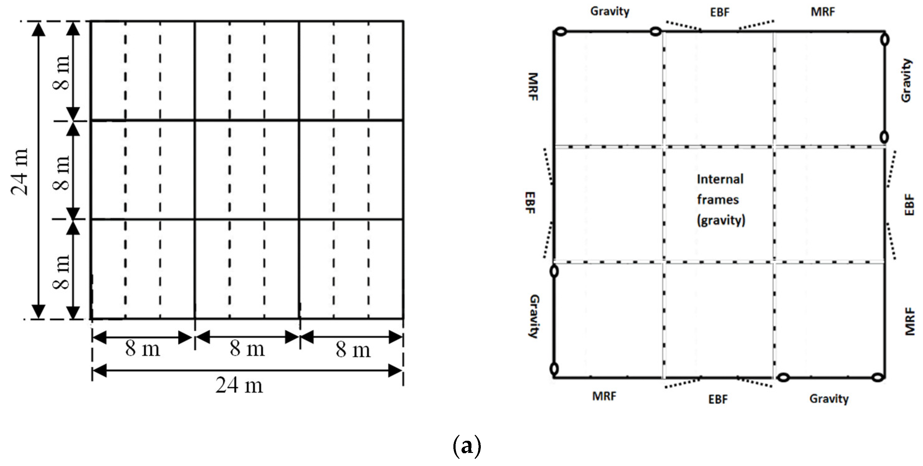
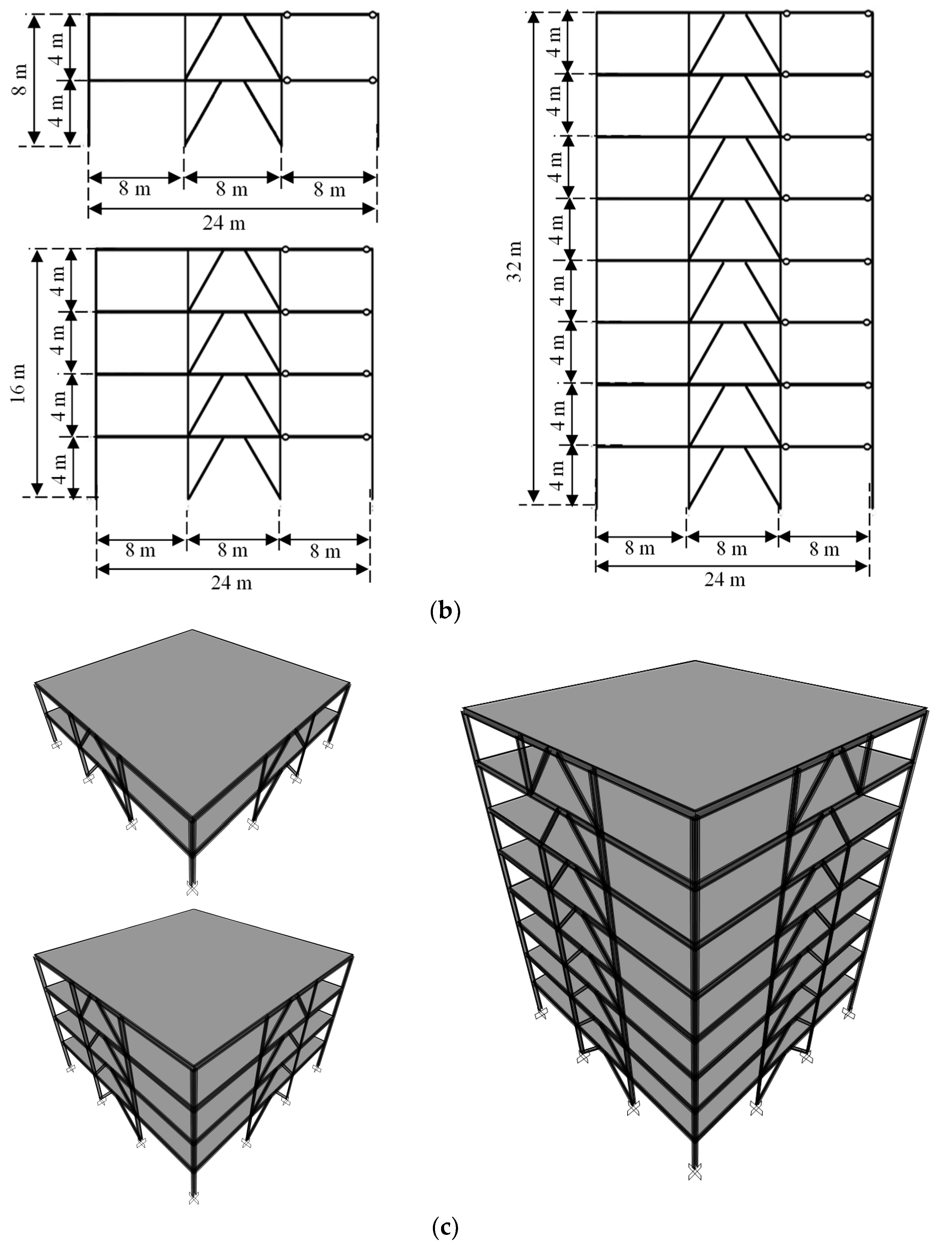
Three buildings were designed with the same plan layout but also varying the number of stories between 2, 4, and 8. The story height was set as a constant, and equal to 4 m. The number of bays in the X and Y directions is 3, each 8 m long (see Figure 1).
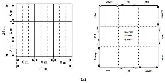
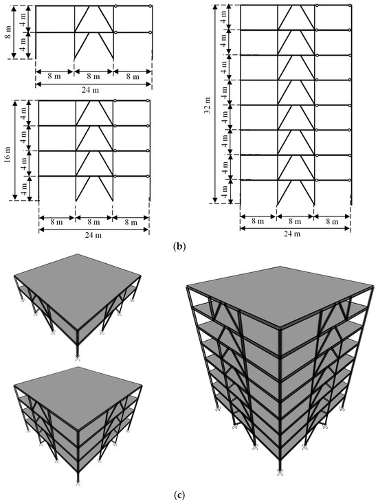
Figure 1.
Plan, side, and 3d views of the investigated structures ((a–c), respectively).
The lateral load-resisting frames in each direction are arranged to achieve independent structural behavior in the X and Y directions, as depicted in Figure 1.
The moment-resisting frames and eccentrically braced frames were designed according to EN1998-1 [20] and EN1993-1-1 [21]. The design behavior factor (q) was assumed to be equal to 6, as this is the maximum recommended value for the EBFs systems.
The dead and live vertical loads were assumed to be equal to 5 and 2 kN/m2 at each story. A peak ground acceleration (PGA) equal to 0.2 g, considering soil type C, and a damping ratio equal to 2% were assumed. According to EN1998-1-1 [20], in the seismic design, the torsional effects were taken into account by magnifying the seismic demand through the factor δ, assumed to be equal to 1.3. Steel of S355 grade was selected for all elements.
The EBFs were designed according to DCH concept [20], in order to enforce the dissipation of the seismic energy through shear plastic hinges in the links.
According to [20], the formation of a global plastic mode of EBFs is guaranteed if the link overstrength ratios Ωi = 1.5 Vp,link,i/VEd,i (where Vp,link,i is the shear plastic strength of the i-th link, and VEd,i is the corresponding shear force demand) are sufficiently uniform along the building height; namely, the maximum ratio does not exceed 1.25 times the minimum value Ω.
The MRFs of the dual configurations were designed in order to resist the complementary seismic effects corresponding to the full development of the plastic mode in the EBFs. In this regard, to estimate the design in dual frames, the two subsystems (MRF and EBF) were fictitiously decoupled. Indeed, as long as the EBFs are elastic, the MRFs can only take a minor amount of the seismic forces. In particular, the braced parts of both dual systems were designed to resist 75% of the design lateral forces, as indicated by AISC341-22 [22]. However, differently from the North American approach, the MRF zones were not designed to resist the complementary 25% of the design forces, but to resist at least 25% of the plastic lateral strength at each story “i”, thus complying with , where VDual,i is the overall lateral strength, which was estimated as , where VEBF,i is the lateral strength value of the EBF part, L is the span length of the bay containing the link, and hi is the inter-story height. This approach leads to larger design forces for the MRF parts than those obtained using 25% of the design force from the reduced response spectrum.
Each building was designed three times, changing the structural system as follows: (i) the first set was designed using only EBFs with short links as lateral load resisting systems, placed in the middle of the structures and identified hereinafter as GEG (i.e., gravity frames, eccentric frames, and gravity frames); (ii) the second set of structures was designed by placing the MRF in a single adjacent bay to the EBF, and it was named MEG (i.e., moment resisting frames, eccentric frames, and gravity frames); (iii) the third set of structures was designed by placing two MRFs adjacent to the EBF and was referred to as MEM (i.e., moment resisting frames, eccentric frames and moment resisting frames).
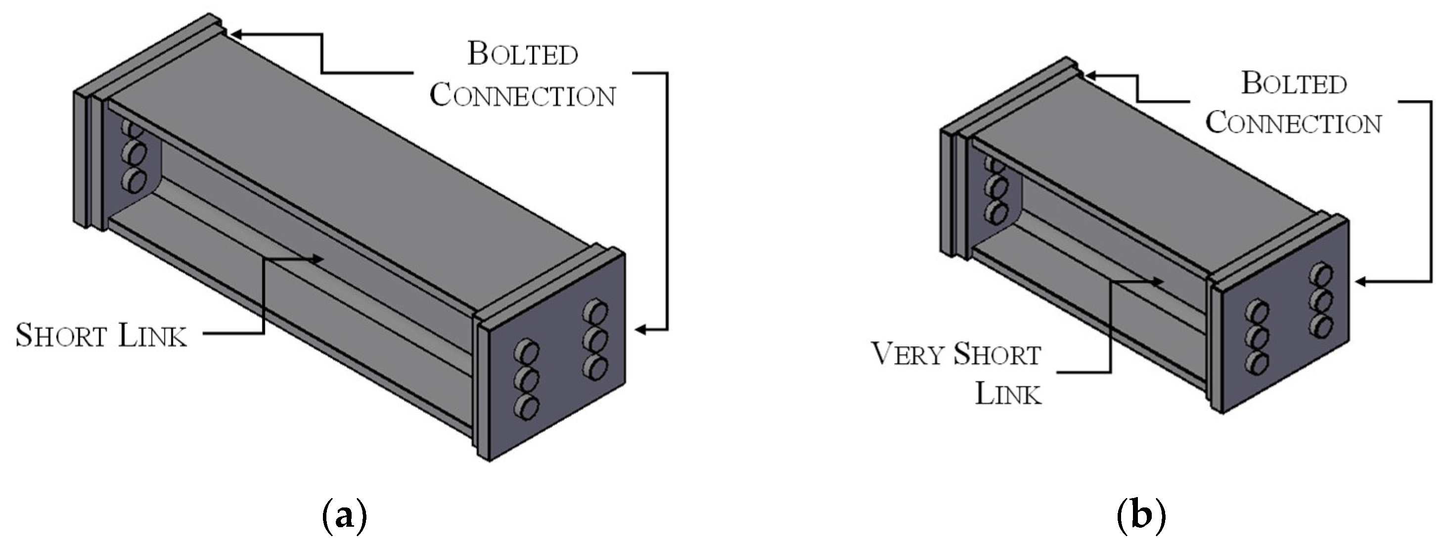
In addition to those nine structures, in order to investigate the influence of the MRFs on the ductility of the EBF dual structures, each structure was designed assuming two alternative configurations (see Figure 2):

Figure 2.
The geometry of the detachable links of conf. 1 (a) and conf. 2 (b).
In configuration 1, the buildings were designed with shear links having lengths as close as possible to the upper value of the mechanical length for short links (i.e., 1.6 Mp/Vp).
In configuration 2, the buildings were designed with very short links, specifically, with lengths of about half the upper value of the mechanical length for short links (i.e., 0.8 Mp/Vp).
3. Designed Structures
All links were designed to be detachable fuses. Therefore, the beams containing the links were designed to resist the maximum expected capacity of the short links. As a consequence, the dimensions of the short links were properly calibrated on the basis of the seismic demand; thus, the design overstrength factors (i.e., the ratios Ωi between the design shear force and the plastic shear resistance of the i-th link) of the short links are close to 1.
The geometries of the structural members of the designed buildings are reported in Table A1, Table A2, Table A3, Table A4, Table A5 and Table A6 in the Appendix A, respectively, for the two-story, four-story and eight-story structures. For the sake of clarity, the link lengths in tables are expressed in meters.
4. Modelling Assumptions
The numerical models were developed using Seismostruct software [23], which is able to predict large displacement behavior in all elements using the fiber (i.e., infrmFB elements [23]) modeling technique, including geometric and material non-linearities.
The fiber models of elements can accurately predict the axial and flexural responses of structural members but are not suitable for capturing the shear response. Hence, lumped shear springs were added at the ends of each link element to simulate both the elastic and plastic behavior of the short links.
The stiffness of the shear springs is calculated as in Equation (1):
where G is the shear elastic modulus of the steel, A is the area of the cross-section, e is the link length, and the shear factor (χ) used to calculate the shear area was determined in Equation (2):
where the following obtain:
b is the width of the cross-section;
d is the depth of the section;
tf is the flange thickness;
i is the radius of gyration;
η is the stiffness parameter, given by 2 tf/(d − tf);
ζ is the stiffness parameter, given by tw/b.
Yield force limit was calculated as per Eurocode, taking only the shear capacity of the web, as summarized in Equation (3), while the ultimate shear capacity of the links was taken to be 50% higher than the yield force (see Equation (4)).
The post-yield stiffness was calculated such that the ultimate capacity would be reached at a plastic link rotation of 0.08 radians (see Equation (5)).
The shear springs were modeled in Seismostruct using link elements as kinematic bilinear springs based on the following parameters (see Figure 3):
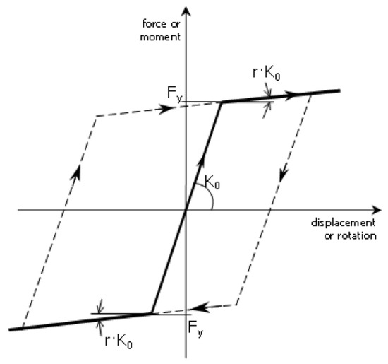
Figure 3.
Link element (shear spring) model in Seismostruct.
- (1)
- Initial stiffness (KL1,0).
- (2)
- Yield force (VP).
- (3)
- Post yield stiffness ratio (KL1,1/KL1,0).
In addition, the reactions of the link springs drop to zero when the links reach their maximum expected shear resistance (i.e., 1.5 Vp).
The Menegotto–Pinto material model, coupled with the hardening model proposed by Filippou et al. [23], was used to simulate the steel’s non-linear behavior. The braces were modeled with an out-of-plane camber equal to 1/1000 their working length to simulate their buckling.
The boundary conditions of braces and beams of EBFs were assumed to be flexurally continuous. In addition, all columns were assumed to be fixed at the base.
The diaphragm constraint was also modelled on each floor to simulate the in-plane rigidity of the slab and to connect the structure to the leaning column, where all masses and the gravity loads acting on the interior frames were applied. The leaning columns have no lateral stiffness and do not interact with the lateral stiffness of the frame.
The static non-linear analyses were performed monitoring the link capacity; in particular, the numerical model accounts for the maximum resistance of the link in terms of both resistance and shear deformation, allowing the link element deletion, once the maximum capacity is reached during the analysis.
5. Non-Linear Static Analyses
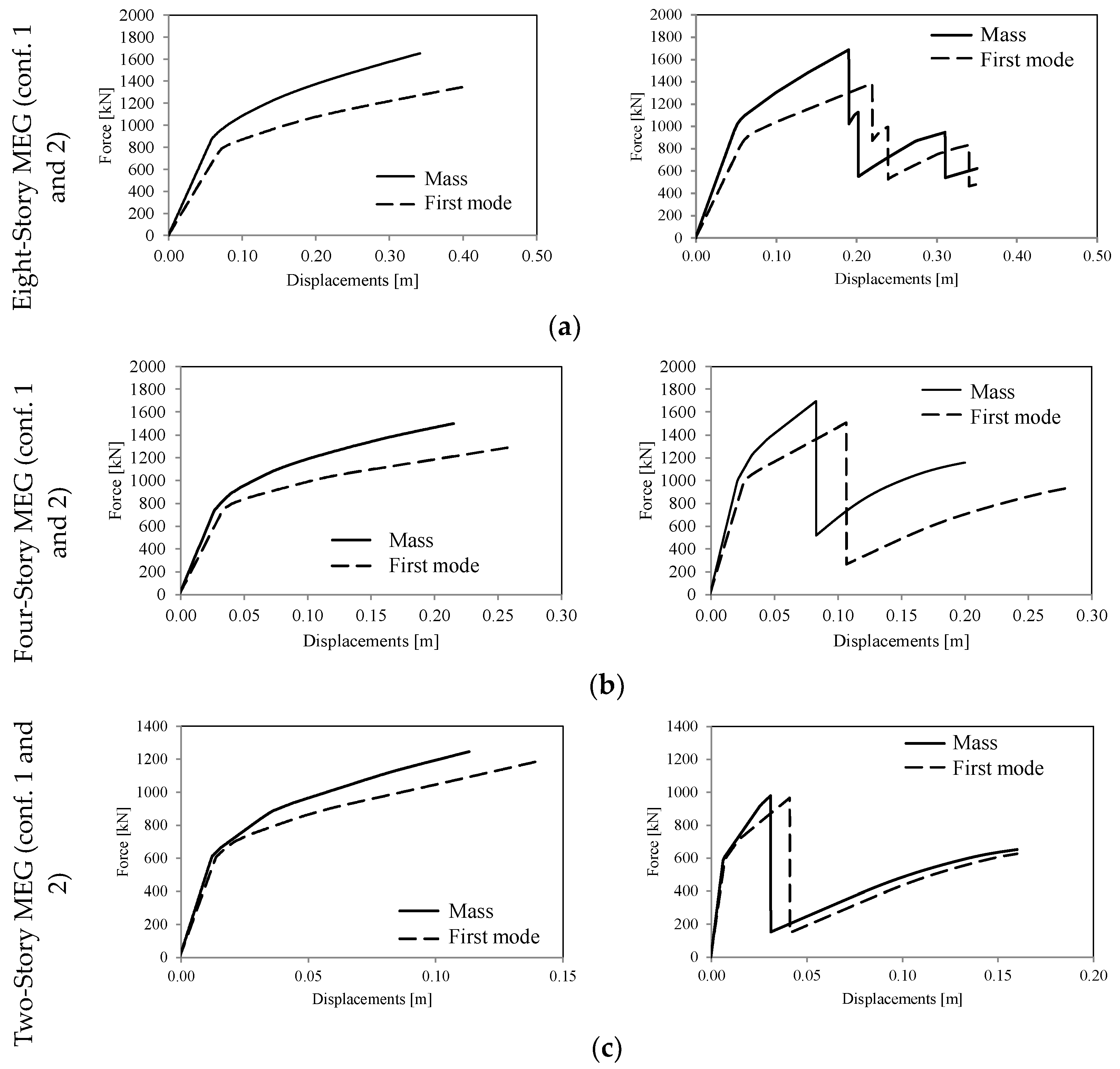
Two lateral force distributions were used to perform the pushover analyses of the structures: one proportional to the masses and another consistent with the fundamental mode of vibration. For the sake of brevity, the comparison between the capacity curves varying the loading pattern is only shown for MEG structures in Figure 4. In fact, the trend is almost the same for all of the other investigated buildings; specifically, the capacity curves evaluated for the mass-proportional loads are systematically characterized by greater stiffness and resistance, as well as smaller displacement capacity, than those evaluated under first-mode proportional loads.

Figure 4.
Comparison of the capacity curves varying the loading pattern (mass vs. first-mode loads) for the 8-, 4-and 2-story buildings ((a–c), respectively).
As anticipated, the push-over analyses were performed considering the deletion of links once their capacity was reached during the analyses. In conf. 2, a larger demand on the very short links can be observed, one which led to their anticipated failure and a sudden loss of structural capacity. Therefore, the push-over resistance increases up to the attainment of the maximum capacity of the first link; after that, a sudden resistance drop can be pointed out. The re-loading branch of the response curve is due to the contribution of the other links.
In all the investigated cases, the structural displacement capacity was verified against the target values for Damage limitation, Significant Damage, and Near Collapse limit states.
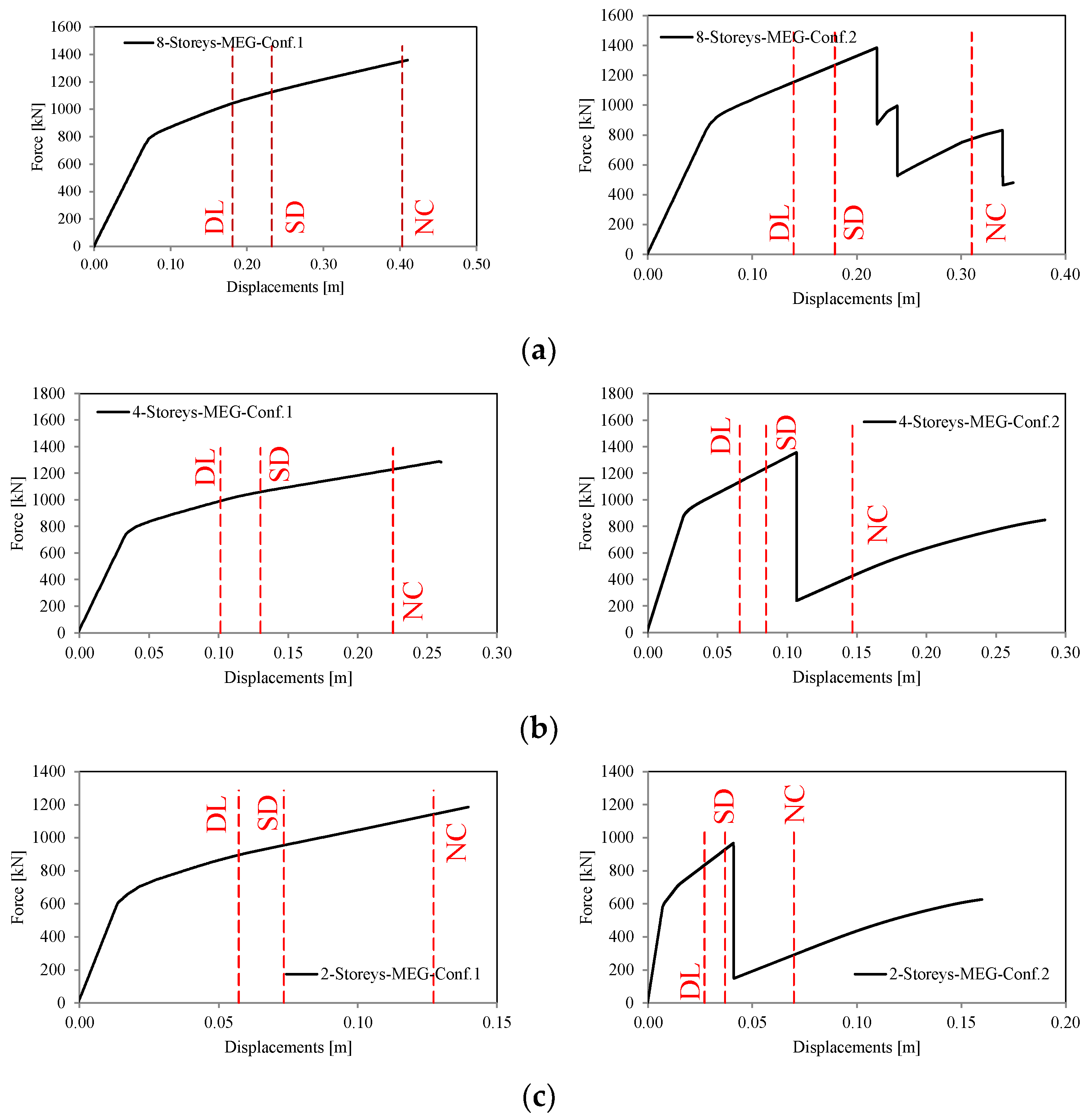
The comparison between the two investigated configurations (i.e., the ones with short and very short links) is depicted in Figure 5.
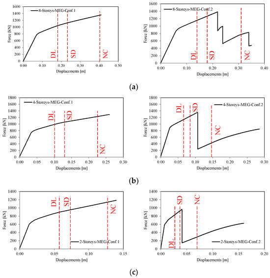
Figure 5.
Comparison between MEG structures in Conf.1 and Conf.2 in terms of force–displacement curves of the 2-, 4-, and 8-story buildings ((a–c), respectively).
From the force–displacement curves, it can be observed that the structures with shorter links show a slightly higher lateral stiffness and peak resistance, mainly due to the different diagonal slopes. However, this configuration shows a smaller ductility with respect to the structure equipped with very short links.
Indeed, the structures equipped with very short links fulfill the drift displacements at both DL and SD but are not able to meet the required displacements at the Near Collapse limit state. In particular, in all the investigated cases with configuration 2, the failure of the links was observed (which corresponds to the sudden loss of capacity of the pushover curves) prior to the NC drift demand. This result suggests that the use of very short links may be not effective, because the shorter the link, the greater is their ductility demand at the same drift with respect to the links of configurations 1.
However, the advantage of very short links (configuration 2) is mainly limited to the smaller forces expected on the connections at the link ends and thus simpler connection details. This aspect can be economically convenient, especially if the detachable links are used with deep sections. Unfortunately, the primary drawback in adopting this type of configuration is that explicit checks have to be made in the design stage to ensure that the deformation capacity of such very-short links suffices for the overall displacement demand, thus requiring at least pushover analyses to check the consistency of the design procedure, since the conventional elastic analyses may not be an efficient way to estimate the ultimate deformations of the building. Nevertheless, the presence of MRFs in combination with EBFs is highly important, because a secondary resisting mechanism activates once the links fail, thus guaranteeing an important reserve of ductility and residual resistance.
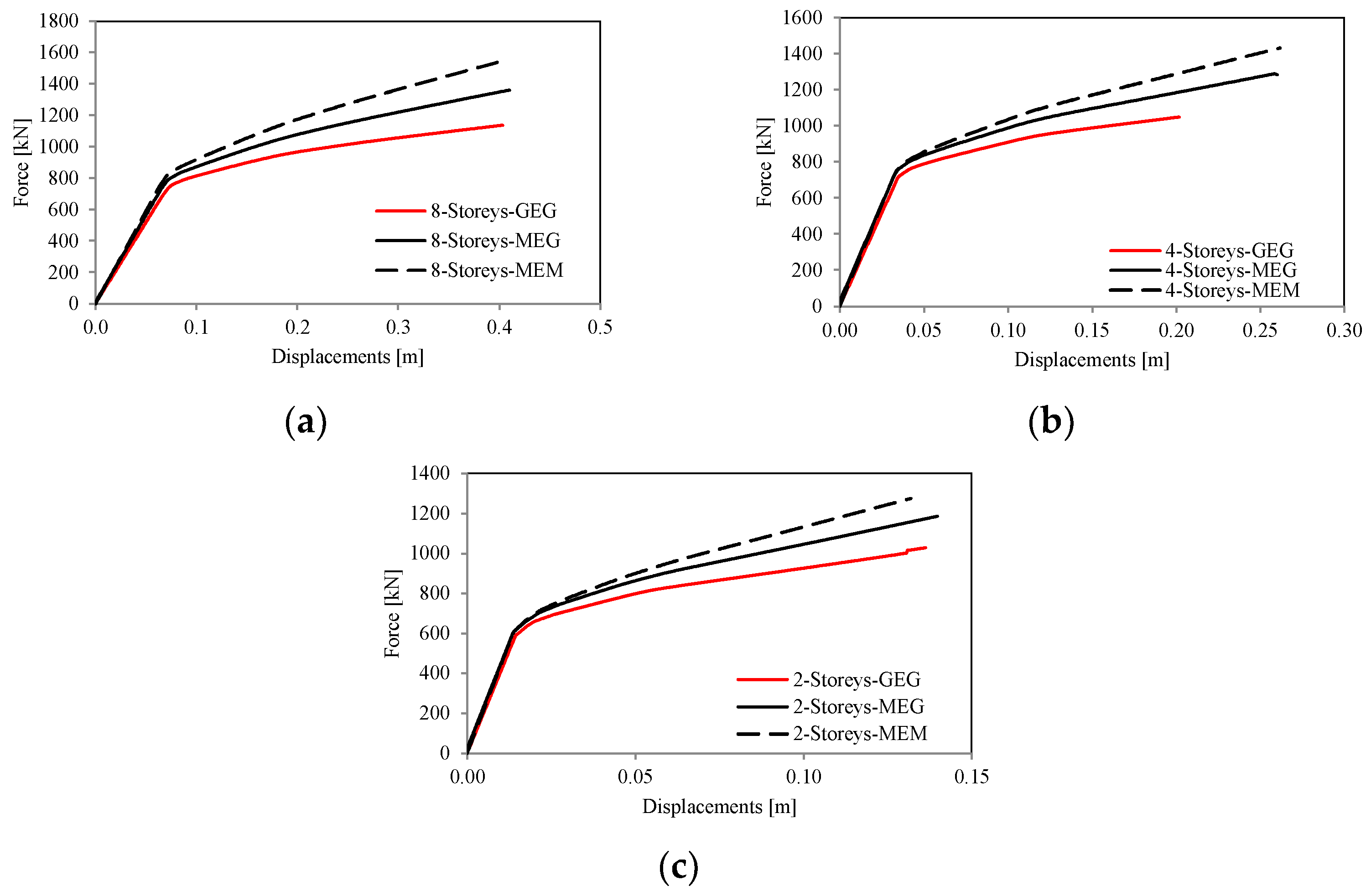
Figure 5 depicts the comparison between the three sets of investigated structures (i.e., GEG, MEG, and MEM) in terms of force–displacement curves. As expected, the structure configurations with two MRFs in conjunction with the EBFs are characterized by higher levels of post-yield rigidity and resistance. However, it should be noted that, since the EBFs mainly govern the structural elastic stiffness, all the investigated configurations have comparable behavior as to initial stiffness. Contrariwise, in increasing the displacement demand, larger differences can be pointed out because the presence of the MRFs allows a better distribution of damage along the building’s height (see Figure 6).
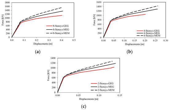
Figure 6.
Static non-linear analysis results in terms of force–displacement curves of the 8-story structures (a), 4-story structures (b), and 2-story structures (c).
As can be observed, dual frames exhibit higher post-yield stiffness than do the EBFs. However, the reason for the large ductility without brace buckling is mainly due to the use of the detachable links; indeed, the link sections can be selected to match closely the design forces, thus ensuring almost equal overstrength factors along the whole height of the building.
In addition, the yielding of the links was observed in all stories and was almost contemporary, as can be seen in the shapes of the pushover curves.
6. Conclusions
A numerical study to investigate the seismic behavior of dual frames with MRFs and EBFs is presented in this paper. The examined dual frames are equipped with short links, and their seismic capacity is evaluated by means of non-linear static analyses. From the observed results the following conclusions can be pointed out:
- The dual frames exhibit a better response than the EBFs because of their greater ductility and post-yield stiffness.
- The presence of the MRFs allows a better plastic distribution among the links for each of the stories.
- Increasing the redundancy of dual frames (i.e., two MRFs in place of one) is beneficial, guaranteeing ductility and preventing unfavorable failure modes.
- The frames with shorter links exhibited higher resistance and rigidity. However, the shorter links do not guarantee satisfactory overall displacement capacity because the deformation demand in the links is almost twice the demand seen in those with the investigated longer links, thus their ultimate deformations are attained at smaller drifts.
- The advantage of very short links is mainly limited to the smaller design forces expected on the connections at the link ends, and thus the simpler connection details. This aspect can be economically convenient, especially if the detachable links are used with deep sections. However, structures with very short links can be characterized by limited displacement capacity because the link deformation demand is higher than in the case of short links, and the link failure is anticipated.
- This study highlights that a lower-bound value associated with the length of short links would be desirable because a structure with very short links can exhibit a limited overall displacement capacity that does not comply with the demand at the Near Collapse limit state.
- Although very short links can be convenient, if detachable links are designed, because of the relatively smaller moments at the ends of the link, the global response of the building would have to be verified through non-linear analysis to control the global displacement capacity and the evolution of the plastic mode of the building.
- Considering the limits of pushover analyses as well as the features of the investigated cases, further experimental and numerical investigations are deemed necessary to develop new rules for the use of such very short elements.
Author Contributions
All authors contributed equally. All authors have read and agreed to the published version of the manuscript.
Funding
This research received no external funding.
Institutional Review Board Statement
Not applicable.
Informed Consent Statement
Not applicable.
Data Availability Statement
The raw data supporting the conclusions of this article will be made available by the authors on request.
Conflicts of Interest
The authors declare no conflicts of interest.
Appendix A
The geometries of the structural members of the designed buildings are reported in Table A1, Table A2, Table A3, Table A4, Table A5 and Table A6.

Table A1.
Cross-section of the 2-story building (conf. 1).
Table A1.
Cross-section of the 2-story building (conf. 1).
| Story | Columns (First/Second/Third Bay) | Beams (First/Second/ Third Bay) | Links | Brace | ||
|---|---|---|---|---|---|---|
| Section | Length [m] | |||||
| GEG | 1 | HEB220/HEB220/HEB220 | IPE450/HEB240/ IPE450 | HEA200 | 1.00 | HEB240 |
| 2 | HEB220/HEB220/HEB220 | IPE450/HEB240/ IPE450 | HEA180 | 0.95 | HEB240 | |
| MEG | 1 | HEB220/HEB220/HEB220 | IPE360/HEB240/ IPE450 | HEA200 | 1.00 | HEB240 |
| 2 | HEB220/HEB220/HEB220 | IPE360/HEB240/ IPE450 | HEA180 | 0.95 | HEB240 | |
| MEM | 1 | HEB220/HEB220/HEB220 | IPE360/HEB240/ IPE360 | HEA200 | 1.00 | HEB240 |
| 2 | HEB220/HEB220/HEB220 | IPE360/HEB240/ IPE360 | HEA180 | 0.95 | HEB240 | |
Table A2.
Cross-section of the 2-story building (conf. 2).
Table A2.
Cross-section of the 2-story building (conf. 2).
| Story | Columns (First/Second/Third Bay) | Beams (First/Second/ Third Bay) | Links | Brace | ||
|---|---|---|---|---|---|---|
| Section | Length [m] | |||||
| GEG | 1 | HEB220/HEB220/HEB220 | IPE450/HEB240/ IPE450 | HEA200 | 0.5 | HEB240 |
| 2 | HEB220/HEB220/HEB220 | IPE450/HEB240/ IPE450 | HEA180 | 0.4 | HEB240 | |
| MEG | 1 | HEB220/HEB220/HEB220 | IPE360/HEB240/ IPE450 | HEA200 | 0.5 | HEB240 |
| 2 | HEB220/HEB220/HEB220 | IPE360/HEB240/ IPE450 | HEA180 | 0.4 | HEB240 | |
| MEM | 1 | HEB220/HEB220/HEB220 | IPE360/HEB240/ IPE360 | HEA200 | 0.5 | HEB240 |
| 2 | HEB220/HEB220/HEB220 | IPE360/HEB240/ IPE360 | HEA180 | 0.4 | HEB240 | |
Table A3.
Cross-section of the 4-story building (conf. 1).
Table A3.
Cross-section of the 4-story building (conf. 1).
| Story | Columns (First/Second/Third Bay) | Beams (First/Second/ Third Bay) | Links | Brace | ||
|---|---|---|---|---|---|---|
| Section | Length [m] | |||||
| GEG | 1 | HEB220/HEB320/HEB220 | IPE450/HEB240/ IPE450 | HEA220 | 1.15 | HEB240 |
| 2 | HEB220/HEB300/HEB220 | IPE450/HEB240/ IPE450 | HEA220 | 1.15 | HEB240 | |
| 3 | HEB220/HEB260/ HEB220 | IPE450/HEB220/ IPE450 | HEA160 | 0.9 | HEB220 | |
| 4 | HEB220/HEB240/ HEB220 | IPE450/HEB220/ IPE450 | HEA140 | 0.75 | HEB180 | |
| MEG | 1 | HEB220/HEB320/HEB220 | IPE360/HEB240/ IPE450 | HEA220 | 1.15 | HEB240 |
| 2 | HEB220/HEB300/HEB220 | IPE360/HEB240/ IPE450 | HEA220 | 1.15 | HEB240 | |
| 3 | HEB220/HEB260/ HEB220 | IPE360/HEB220/ IPE450 | HEA160 | 0.9 | HEB220 | |
| 4 | HEB220/HEB240/ HEB220 | IPE360/HEB220/ IPE450 | HEA140 | 0.75 | HEB180 | |
| MEM | 1 | HEB220/HEB320/HEB220 | IPE360/HEB240/ IPE360 | HEA220 | 1.15 | HEB240 |
| 2 | HEB220/HEB300/HEB220 | IPE360/HEB240/ IPE360 | HEA220 | 1.15 | HEB240 | |
| 3 | HEB220/HEB260/ HEB220 | IPE360/HEB220/ IPE | HEA160 | 0.9 | HEB220 | |
| 4 | HEB220/HEB240/ HEB220 | IPE360/HEB220/PE360 | HEA140 | 0.75 | HEB180 | |
Table A4.
Cross-section of the 4-story building (conf. 2).
Table A4.
Cross-section of the 4-story building (conf. 2).
| Story | Columns (First/Second/Third Bay) | Beams (First/Second/ Third Bay) | Links | Brace | ||
|---|---|---|---|---|---|---|
| Section | Length [m] | |||||
| GEG | 1 | HEB220/HEM300/HEB220 | IPE450/HEB240/ IPE450 | HEB220 | 0.6 | HEB240 |
| 2 | HEB220/HEB300/HEB220 | IPE450/HEB240/ IPE450 | HEB220 | 0.6 | HEB240 | |
| 3 | HEB220/HEB260/ HEB220 | IPE450/HEB220/ IPE450 | HEB180 | 0.5 | HEB220 | |
| 4 | HEB220/HEB240/ HEB220 | IPE450/HEB220/ IPE450 | HEB140 | 0.4 | HEB180 | |
| MEG | 1 | HEB220/HEB300/HEB220 | IPE360/HEB240/ IPE450 | HEB220 | 0.6 | HEB240 |
| 2 | HEB220/HEB300/HEB220 | IPE360/HEB240/ IPE450 | HEB220 | 0.6 | HEB240 | |
| 3 | HEB220/HEB260/ HEB220 | IPE360/HEB220/ IPE450 | HEB180 | 0.5 | HEB220 | |
| 4 | HEB220/HEB240/ HEB220 | IPE360/HEB220/ IPE450 | HEB140 | 0.4 | HEB180 | |
| MEM | 1 | HEB220/HEB300/HEB220 | IPE360/HEB240/ IPE36 | HEB220 | 0.6 | HEB240 |
| 2 | HEB220/HEB300/HEB220 | IPE360/HEB240/ IPE360 | HEB220 | 0.6 | HEB240 | |
| 3 | HEB220/HEB260/ HEB220 | IPE360/HEB220/ IPE360 | HEB180 | 0.5 | HEB220 | |
| 4 | HEB220/HEB240/ HEB220 | IPE360/HEB220/ IPE360 | HEB140 | 0.4 | HEB180 | |
Table A5.
Cross-section of the 8-story building (conf. 1).
Table A5.
Cross-section of the 8-story building (conf. 1).
| Story | Columns (First/Second/Third Bay) | Beams (First/Second/ Third Bay) | Links | Brace | ||
|---|---|---|---|---|---|---|
| Section | Length [m] | |||||
| GEG | 1 | HEB260/HEM400*/HEB260 | IPE450/HEB260/IPE450 | HEB200 | 1.0 | HEB260 |
| 2 | HEB260/HEM360*/HEB260 | IPE450/HEB260/IPE450 | HEB200 | 1.1 | HEB260 | |
| 3 | HEB260/HEM360*/HEB260 | IPE450/HEB260/IPE450 | HEB180 | 1.0 | HEB260 | |
| 4 | HEB260/HEB360*/HEB260 | IPE450/HEB240/IPE450 | HEB180 | 1.0 | HEB240 | |
| 5 | HEB260/HEB360/HEB260 | IPE450/HEB220/IPE450 | HEB160 | 0.9 | HEB220 | |
| 6 | HEB260/HEB320/HEB260 | IPE450/HEB220/IPE450 | HEA180 | 0.9 | HEB200 | |
| 7 | HEB260/HEB300/HEB260 | IPE450/HEB220/IPE450 | HEB140 | 0.8 | HEB180 | |
| 8 | HEB260/HEB300/HEB260 | IPE360/HEB220/IPE450 | HEB100 | 0.56 | HEB160 | |
| MEG | 1 | HEB260*/HEM400*/HEB260 | IPE360/HEB260/IPE450 | HEB200 | 1.0 | HEB260 |
| 2 | HEB260*/HEM360*/HEB260 | IPE360/HEB260/IPE450 | HEB200 | 1.1 | HEB260 | |
| 3 | HEB260*/HEM360*/HEB260 | IPE360/HEB260/IPE450 | HEB180 | 1.0 | HEB260 | |
| 4 | HEB260*/HEB360*/HEB260 | IPE360/HEB240/IPE450 | HEB180 | 1.0 | HEB240 | |
| 5 | HEB260/HEB360/HEB260 | IPE360/HEB220/IPE450 | HEB160 | 0.9 | HEB220 | |
| 6 | HEB260/HEB320/HEB260 | IPE360/HEB220/IPE450 | HEA180 | 0.9 | HEB200 | |
| 7 | HEB260/HEB300/HEB260 | IPE360/HEB220/IPE450 | HEB140 | 0.8 | HEB180 | |
| 8 | HEB260/HEB300/HEB260 | IPE360/HEB220/IPE450 | HEB100 | 0.56 | HEB160 | |
| MEM | 1 | HEB260*/HEM400*/HEB260* | IPE360/HEB260/IPE360 | HEB200 | 1.0 | HEB260 |
| 2 | HEB260*/HEM360*/HEB260* | IPE360/HEB260/IPE360 | HEB200 | 1.1 | HEB260 | |
| 3 | HEB260*/HEM360*/HEB260* | IPE360/HEB260/IPE360 | HEB180 | 1.0 | HEB260 | |
| 4 | HEB260*/HEB360*/HEB260* | IPE360/HEB240/IPE360 | HEB180 | 1.0 | HEB240 | |
| 5 | HEB260/HEB360/HEB260 | IPE360/HEB220/IPE360 | HEB160 | 0.9 | HEB220 | |
| 6 | HEB260/HEB320/HEB260 | IPE360/HEB220/IPE360 | HEA180 | 0.9 | HEB200 | |
| 7 | HEB260/HEB300/HEB260 | IPE360/HEB220/IPE360 | HEB140 | 0.8 | HEB180 | |
| 8 | HEB260/HEB300/HEB260 | IPE360/HEB220/IPE360 | HEB100 | 0.56 | HEB160 | |
* Steel grade: S460 sections.
Table A6.
Cross-section of the 8-story building (conf. 2).
Table A6.
Cross-section of the 8-story building (conf. 2).
| Story | Columns (First/Second/Third Bay) | Beams (First/Second/ Third Bay) | Links | Brace | ||
|---|---|---|---|---|---|---|
| Section | Length [m] | |||||
| GEG | 1 | HEB260/HEM400/ HEB260 | IPE450/HEB260/IPE450 | HEB200 | 0.7 | HEB260 |
| 2 | HEB260/HEM360/ HEB260 | IPE450/HEB260/IPE450 | HEB200 | 0.7 | HEB260 | |
| 3 | HEB260/HEM360/ HEB260 | IPE450/HEB260/IPE450 | HEB200 | 0.7 | HEB260 | |
| 4 | HEB260/HEB360/ HEB260 | IPE450/HEB240/IPE450 | HEA200 | 0.7 | HEB240 | |
| 5 | HEB260/HEB360/ HEB260 | IPE450/HEB220/IPE450 | HEA180 | 0.6 | HEB220 | |
| 6 | HEB260/HEB320/ HEB260 | IPE450/HEB220/IPE450 | HEA160 | 0.5 | HEB200 | |
| 7 | HEB260/HEB300/ HEB260 | IPE450/HEB220/IPE450 | HEA140 | 0.5 | HEB180 | |
| 8 | HEB260/HEB300/ HEB260 | IPE360/HEB220/IPE450 | HEA140 | 0.4 | HEB160 | |
| MEG | 1 | HEB260/HEM400/HEB260 | IPE360/HEB260/IPE450 | HEB200 | 0.7 | HEB260 |
| 2 | HEB260/HEM360/HEB260 | IPE360/HEB260/IPE450 | HEB200 | 0.7 | HEB260 | |
| 3 | HEB260/HEM360/HEB260 | IPE360/HEB260/IPE450 | HEB200 | 0.7 | HEB260 | |
| 4 | HEB260/HEB360/HEB260 | IPE360/HEB240/IPE450 | HEA200 | 0.7 | HEB240 | |
| 5 | HEB260/HEB360/HEB260 | IPE360/HEB220/IPE450 | HEA180 | 0.6 | HEB220 | |
| 6 | HEB260/HEB320/HEB260 | IPE360/HEB220/IPE450 | HEA160 | 0.5 | HEB200 | |
| 7 | HEB260/HEB300/HEB260 | IPE360/HEB220/IPE450 | HEA140 | 0.5 | HEB180 | |
| 8 | HEB260/HEB300/HEB260 | IPE360/HEB220/IPE450 | HEA140 | 0.4 | HEB160 | |
| MEM | 1 | HEB260/HEM400/HEB260 | IPE360/HEB260/IPE360 | HEB200 | 0.7 | HEB260 |
| 2 | HEB260/HEM360/HEB260 | IPE360/HEB260/IPE360 | HEB200 | 0.7 | HEB260 | |
| 3 | HEB260/HEM360/HEB260 | IPE360/HEB260/IPE360 | HEB200 | 0.7 | HEB260 | |
| 4 | HEB260/HEB360/HEB260 | IPE360/HEB240/IPE360 | HEA200 | 0.7 | HEB240 | |
| 5 | HEB260/HEB360/HEB260 | IPE360/HEB220/IPE360 | HEA180 | 0.6 | HEB220 | |
| 6 | HEB260/HEB320/HEB260 | IPE360/HEB220/IPE360 | HEA160 | 0.5 | HEB200 | |
| 7 | HEB260/HEB300/HEB260 | IPE360/HEB220/IPE360 | HEA140 | 0.5 | HEB180 | |
| 8 | HEB260/HEB300/HEB260 | IPE360/HEB220/IPE360 | HEA140 | 0.4 | HEB160 | |
References
- Tartaglia, R.; D’Aniello, M.; Landolfo, R. Seismic performance of Eurocode-compliant ductile steel MRFs. Earthq. Eng. Struct. Dyn. 2022, 51, 2527–2552. [Google Scholar] [CrossRef]
- Montuori, R.; Nastri, E.; Piluso, V. Theory of plastic mechanism control: A new approach for the optimization of seismic resistant steel frames. Earthq. Eng. Struct. Dyn. 2022, 51, 3598–3619. [Google Scholar] [CrossRef]
- D’Aniello, M.; Tartaglia, R.; Landolfo, R.; Jaspart, J.-P.; Demonceau, J.-F. Seismic pre-qualification tests of EC8-compliant external extended stiffened end-plate beam-to-column joints. Eng. Struct. 2023, 291, 116386. [Google Scholar] [CrossRef]
- Dubina, D.; Dinu, F.; Stratan, A. Resilience of dual steel-dual frame buildings in seismic areas. Steel Constr. 2021, 14, 150–166. [Google Scholar] [CrossRef]
- Ioan, A.; Stratan, A.; Dubină, D.; Poljanšek, M.; Molina, F.J.; Taucer, F.; Pegon, P.; Sabău, G. Experimental validation of re-centring capability of eccentrically braced frames with removable links. Eng. Struct. 2016, 113, 335–346. [Google Scholar] [CrossRef]
- Sina, K.A.; Topkaya, C. A review of research on steel eccentrically braced frames. J. Constr. Steel Res. 2017, 128, 53–73. [Google Scholar]
- Bosco, M.; Ghersi, A.; Marino, E.M.; Rossi, P.R. Seismic response and behavior factor of dual eccentrically braced frames designed by Eurocode 8. In Proceedings of the Second European Conference on Earthquake Engineering and Seismology, Istanbul, Turkey, 24–29 August 2014. [Google Scholar]
- Bosco, M.; Marino, E.M.; Rossi, P.R. Critical review of the EC8 design provisions for buildings with eccentric braces. Earthq. Struct. 2015, 8, 1407–1433. [Google Scholar] [CrossRef]
- Bosco, M.; Marino, E.M.; Rossi, O.R. A design procedure for dual eccentrically braced—Moment resisting frames in the framework of Eurocode 8. Eng. Struct. 2017, 130, 198–215. [Google Scholar] [CrossRef]
- Mansour, N. Development of the Design of Eccentrically Braced Frames with Replaceable Shear Links. Ph.D. Thesis, University of Toronto, Toronto, ON, Canada, 2010. [Google Scholar]
- Fussell, A.J.; Clifton, G.C.; Mago, N. Development and research of eccentrically braced frames with replaceable active links. In Proceedings of the NZSEE Conference, Auckland, New Zealand, 21–23 March 2014. [Google Scholar]
- Ioan, A.; Stratan, A.; Dubina, D. Numerical simulation of bolted links removal in eccentrically braced frames. Pollack Period. 2013, 8, 15–26. [Google Scholar] [CrossRef]
- Dubina, D.; Stratan, A.; Ioan, A. Recentering Dual eccentrically braced frames with removable links. Proc. Rom. Acad. 2016, 17, 167–177. [Google Scholar]
- Chesoan, A.; Stratan, A.; Dubina, D. Design implementation of re-centring dual eccentrically braced frames with removable links. Soil Dyn. Earthq. Eng. 2018, 112, 174–184. [Google Scholar] [CrossRef]
- Dubina, D.; Stratan, A.; Dinu, F. Recentering capacity of dual-steel frames. Steel Constr. 2011, 4, 73–84. [Google Scholar] [CrossRef]
- Chen, G.; Yang, J.; Liu, Y.; Kitahara, T.; Beer, M. An energy-frequency parameter for earthquake ground motion intensity measure. Earthq. Eng. Struct. Dyn. 2023, 52, 271–284. [Google Scholar] [CrossRef]
- Chen, G.; Yang, J.; Wang, R.; Li, K.; Liu, Y.; Beer, M. Seismic damage analysis due to near-fault multipulse ground motion. Earthq. Eng. Struct. Dyn. 2023, 52, 5099–5116. [Google Scholar] [CrossRef]
- Kazemi, F.; Asgarkhani, N.; Jankowski, R. Machine learning-based seismic response and performance assessment of reinforced concrete buildings. Arch. Civ. Mech. Eng. 2023, 23, 94. [Google Scholar] [CrossRef]
- Kazemi, F.; Asgarkhani, N.; Jankowski, R. Machine learning-based seismic fragility and seismic vulnerability assessment of reinforced concrete structures. Soil Dyn. Earthq. Eng. 2023, 166, 107761. [Google Scholar] [CrossRef]
- Eurocode EN 1998-1; Eurocode 8—Design of Structures for Earthquake Resistance—Part 1: General Rules, Seismic Actions and Rules for Buildings. European Commission: Brussels, Belgium, 2004.
- Eurocode EN 1993-1-1; Eurocode 3 Design of Steel Structures—Part 1-1: General Rules and Rules for Buildings. European Commission: Brussels, Belgium, 2005.
- ANSI/AISC 341-22; Seismic Provisions for Structural Steel Buildings. American Institute of Steel Construction, Inc.: Chicago, IL, USA, 2022.
- Seismosoft. SeismoStruct v2024 (2024)—A Computer Program for Static and Dynamic Nonlinear Analysis of Framed Structures. Available online: http://www.seismosoft.com (accessed on 30 October 2023).

Disclaimer/Publisher’s Note: The statements, opinions and data contained in all publications are solely those of the individual author(s) and contributor(s) and not of MDPI and/or the editor(s). MDPI and/or the editor(s) disclaim responsibility for any injury to people or property resulting from any ideas, methods, instructions or products referred to in the content. |
© 2024 by the authors. Licensee MDPI, Basel, Switzerland. This article is an open access article distributed under the terms and conditions of the Creative Commons Attribution (CC BY) license (https://creativecommons.org/licenses/by/4.0/).