Review

Magnetic Negative Stiffness Devices for Vibration Isolation Systems: A State-of-the-Art Review from Theoretical Models to Engineering Applications

1
College of Naval Architecture and Ocean, Naval University of Engineering, Wuhan 430033, China
2
School of Mechanical Engineering, Hubei University of Technology, Wuhan 430068, China
*
Author to whom correspondence should be addressed.
Appl. Sci. 2024, 14(11), 4698; https://doi.org/10.3390/app14114698
Submission received: 16 April 2024 / Revised: 19 May 2024 / Accepted: 24 May 2024 / Published: 29 May 2024
(This article belongs to the Section Acoustics and Vibrations)

Abstract

:
This paper presents a comprehensive state-of-the-art review of magnetic negative stiffness (MNS) devices in the realm of vibration isolation systems, spanning from foundational theoretical models to practical engineering applications. The emergence of MNS technology represents a significant advancement in the field of vibration isolation, introducing a method capable of achieving near-zero stiffness to effectively attenuate low-frequency vibration. Through a systematic exploration of the evolution of vibration isolation methodologies—encompassing passive, active, and hybrid techniques—this article elucidates the underlying principles of quasi-zero stiffness (QZS) and investigates various configurations of MNS isolators, such as the linear spring, bending beam, level spring-link, and cam-roller designs. Our comprehensive analysis extends to the optimization and application of these isolators across diverse engineering domains, highlighting their pivotal role in enhancing the isolation efficiency against low-frequency vibrations. By integrating experimental validations with theoretical insights, this study underscores the transformative potential of MNS devices in redefining vibration isolation capabilities, particularly in expanding the isolation frequency band while preserving the load-bearing capacities. As the authors of this review, not only are the current advancements within MNS device research cataloged but also future trajectories are projected, advocating for continued innovation and tailored designs to fully exploit the advantages of MNS technology in specialized vibration isolation scenarios.

1. Introduction

Vibration, characterized by the oscillation of an object around its equilibrium, is present in diverse domains of human activity, including machinery [1,2,3], transportation [4], aerospace [5], and bridges [6]. This phenomenon is universally present in nature, exerting a constant influence on our surroundings. Human perception of sound and sight relies on the vibration of the eardrum and light waves, respectively. The process of breathing is closely linked to the oscillation of the lungs. In industrial settings, vibrating screens, conveyors, and seismographs play a pivotal role in enhancing productivity and safety. Nonetheless, numerous mechanical vibrations pose inherent risks. For instance, in maritime applications, structural vibration may arise from machinery operation, shaft systems, propellers, and wave interactions, affecting both global and local dynamics, including piping systems. Extensive vibration displacement can render a vessel inoperable. Moreover, with the increasing demand for precision and ultra-precision equipment, the significance of controlling vibration environments and optimizing working conditions has escalated for vehicles, vessels, spacecraft, and other machinery. By employing a diverse array of vibration isolation materials and design methodologies, including suspension systems, shock absorbers, and acoustic insulation, the propagation of vibrations from both the interior and the exterior of the vehicle is significantly mitigated, yielding enhancements in passenger comfort and providing a quieter, smoother, and safer journey, while concurrently safeguarding vital vehicle components against potential damage [7,8,9]. In alternative contexts, even the most minute vibration may impinge upon the stealth capabilities of vessels and the operational efficiency of spacecraft [10,11,12]. Research into vibration isolation technology, particularly low-frequency isolation techniques, holds immense significance.
Vibration isolation entails the suppression of vibrations in a controlled object by strategically isolating the vibration source through a dedicated system. In practical engineering applications, vibrations transmitted from the foundation to the equipment are primarily mitigated using vibration isolators [13]. A vibration isolator constitutes an elastic element that strategically connects equipment to a foundation. The primary function of a vibration isolator is to reduce or completely eliminate the transmission of vibrational forces between the foundation and the equipment. Classical vibration studies indicate that a linear vibration isolator can effectively attenuate vibrations exceeding the natural frequency of the isolation system by a specified multiplicative factor [14]. To effectively mitigate low-frequency vibrations, reducing the natural frequency of the isolation system is imperative. An effective strategy to accomplish this involves diminishing the stiffness of the isolation system [15]. However, this approach will result in increased displacement borne by the isolation system and a decreased load-bearing capacity. To address this challenge, QZS isolators have been developed in engineering practice.
The progressive development of vibration isolation techniques has been motivated by the imperative to safeguard delicate equipment [16], enhance the comfort of transportation [17], and mitigate the adverse effects of vibrations on structural integrity [18]. Diverse methodologies have been devised over the course of time to meet these exigencies. The subsequent delineation encapsulates pivotal stages in the progressive development of vibration isolation techniques.
Passive isolation techniques constituted the initial methodologies employed to attenuate vibrations. Passive methodologies for dampening vibrations encompass the utilization of vibration isolators, pads, and mounts affording cushioning. These methodologies are efficacious in mitigating the deleterious effects of vibrations on the system [19].
Active vibration control techniques employ sensors for vibration detection and actuators to generate real-time counteractive forces [20]. These systems continuously monitor vibrations and adjust counteractive forces to minimize the transmitted vibrations. Active techniques are especially effective for reducing vibrations in sensitive equipment and precision machinery. Farshidianfar [21] systematically investigated the application of active vibration isolation to reduce the vibrations transmitted from a vibrating base to sensitive equipment and from machinery to the foundation. The controller, configured as static output feedback, was contemplated for designing the components of the active isolation system. Active control was facilitated through the utilization of H∞ control criteria for designing this controller. This criterion was formulated as a cost function and subsequently optimized using the Particle Swarm Optimization (PSO) algorithm.
Mass-spring systems were developed to isolate vibrations by introducing an additional mass and a set of springs between the source of vibration and the structure [22,23]. The mass-spring system functions as a low-pass filter, effectively attenuating vibrations at specific frequencies.
Tuned mass dampers (TMDs) are devices comprising a mass connected to a structure via a series of springs and dampers [24,25] TMDs are designed to resonate at a specific frequency, counteracting and reducing vibrations at that frequency. They are commonly used in tall buildings, bridges, and other structures to mitigate vibrations induced by wind [26].
Hybrid systems: Recently, hybrid techniques combining passive and active elements have gained popularity [27,28,29]. These systems utilize a combination of passive damping materials, mechanical systems, and active control mechanisms to achieve optimal vibration isolation. Hybrid systems provide enhanced performance, adaptability, and versatility across various applications. A brief introduction to the negative stiffness phenomenon would be beneficial for understanding the operation of hybrid systems. Negative stiffness occurs when the restoring force of a system decreases with increasing displacement, which can lead to enhanced vibration isolation capabilities. This phenomenon can be realized through specific configurations of mechanical or magnetic components, allowing for improved performance in various vibration isolation applications. A novel three-dimensional hybrid isolation platform was proposed by Xie [30]. To isolate the horizontal and vertical vibrations simultaneously, the platform was designed as a combination of a rolling isolation system and four three-parameter isolators with active damping. Magnetorheological elastomer (MRE), a field-dependent smart material, has found wide application in base isolation for reducing vibrations. However, the MRE isolation system frequently encounters significant drift during strong earthquakes, potentially leading to mechanical failure. Moreover, its performance in the low-frequency range remains constrained. To address these issues, Jin [31] proposed a hybrid vibration isolation system comprising four stiffness-softening MRE isolators and a passive ball-screw inerter.
Throughout the development of vibration isolation techniques, the emphasis has been on enhancing performance, adaptability, and efficiency while addressing the specific requirements of diverse applications. As technology continues to advance, further innovations in this field can be expected, leading to more effective and versatile vibration isolation solutions.

2. Fundamental Principles of Quasi-Zero Stiffness

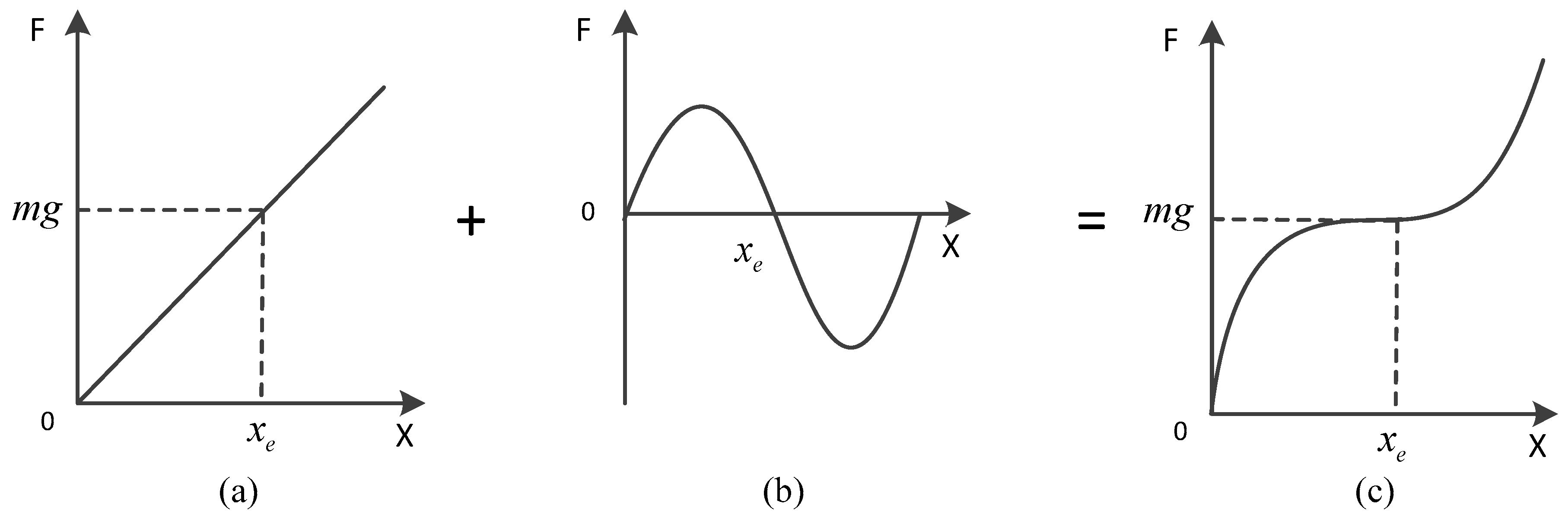
2.1. Basic Principles of QZS

Static stiffness refers to the system’s resistance to static loads, while dynamic stiffness is the system’s resistance to dynamic loads such as vibrations. QZS vibration isolators are crafted via the parallel integration of positive and negative stiffness mechanisms, culminating in a total stiffness approaching zero. The load-carrying capacity of the isolator is governed by the positive stiffness mechanism, while the negative stiffness mechanism regulates the dynamic stiffness of the system. Collaboration between these components results in a reduction in the intrinsic frequency while maintaining the bearing capacity, thereby expanding the frequency band for vibration isolation. Within a specified range, the QZS vibration isolation system achieves near-zero total stiffness through the incorporation of a negative stiffness mechanism, dimensions, and system parameters, and by employing positive and negative stiffness mechanisms in parallel to offset some of the positive stiffness within the equilibrium range. This system not only showcases the outstanding load-bearing capability of the positive stiffness mechanism but also demonstrates reduced dynamic stiffness.
Figure 1 illustrates the characteristic curve of the QZS vibration isolator. The mass of the isolated object is denoted by m and x e represents the equilibrium position of the system. At this juncture, the total stiffness of the system equals the summation of the positive and negative stiffness components. Through adjustments to the positive stiffness mechanism, the positive stiffness consistently surpasses the absolute value of the negative stiffness mechanism’s stiffness. Consequently, the system’s total stiffness approaches zero, thereby diminishing the intrinsic frequency of the isolation system and enhancing its low-frequency isolation capacity. The QZS isolation system distinguishes itself from high static and low dynamic stiffness isolation systems by virtue of the proximity of its total stiffness to zero near the static equilibrium position. Figure 1a represents positive stiffness, where the restoring force increases linearly with the displacement. This is the typical behavior of a conventional spring. Figure 1b shows negative stiffness, where the restoring force decreases with the displacement. The point x e in this figure denotes the static equilibrium position at which the system achieves quasi-zero stiffness. At x e , the negative stiffness counteracts the positive stiffness, resulting in a total stiffness that is near zero. Figure 1c depicts the quasi-zero stiffness (QZS) condition, where the combination of positive and negative stiffness elements creates a system that has very low stiffness around the equilibrium position x e . This configuration allows for effective vibration isolation by minimizing the system’s natural frequency. The high static and low dynamic stiffness isolation system lacks the capability of structural self-adjustment, thus culminating in a system possessing a total stiffness nearing zero near the static equilibrium position.

2.2. Basic Types of QZS Vibration Isolators

Scholars both domestically and internationally have conducted thorough and comprehensive investigations into the theoretical and dynamic characteristics of QZS vibration isolation systems, thereby offering technical underpinnings for more effectively translating theoretical inquiries into engineering applications. In researching and applying QZS vibration isolators, designing a negative stiffness structure with exceptional negative stiffness characteristics stands as the most crucial aspect. In the late 1980s, Alabuzhev et al. [32] authored a seminal work on QZS vibration isolators, introducing the pertinent theory of such isolators. Additionally, the authors put forth four structures exhibiting quasi-zero dynamic stiffness characteristics, utilizing inclined springs, buckled beams, level spring-links, and cam-roller types, as depicted in Figure 2. Subsequently, research into high static and low dynamic stiffness vibration isolators has been predominantly influenced by these four models.
Diverse structural configurations of vibration isolators have been conceived by scholars both domestically and internationally, grounded on the principle of high static and low dynamic stiffness. Their dynamic characteristics and engineering applications have been exhaustively investigated. For instance, Carrella et al. [33,34] proposed a QZS vibration isolator featuring a slanting spring as the negative stiffness mechanism, as illustrated in Figure 3. The authors derived the conditions for the QZS characteristics of this vibration isolator through static analyses. They subsequently optimized the negative stiffness interval of the QZS isolator and analyzed the force transfer rate of the isolator under conditions of nonlinear stiffness in the inclined spring. Furthermore, the authors pioneered the concept of high static and low dynamic stiffness. They scrutinized the transfer rates of the force and displacement in the high static and low dynamic stiffness isolator, offering conditions to mitigate the amplitude jumps in the vibration isolation system. Carrella and colleagues also showcased a high static and low dynamic stiffness isolator utilizing permanent magnets as the negative stiffness mechanism, as depicted in Figure 4. The vibration isolator’s restoring force and stiffness characteristics were ascertained through static analysis. The test results indicated that the introduction of the negative stiffness mechanism decreased the intrinsic frequency of the vibration isolator by approximately 7 Hz, thereby yielding a discernible vibration isolation effect.
This section categorizes the existing QZS vibration isolators into the following classifications based on the design principles of the prevailing negative stiffness structures:

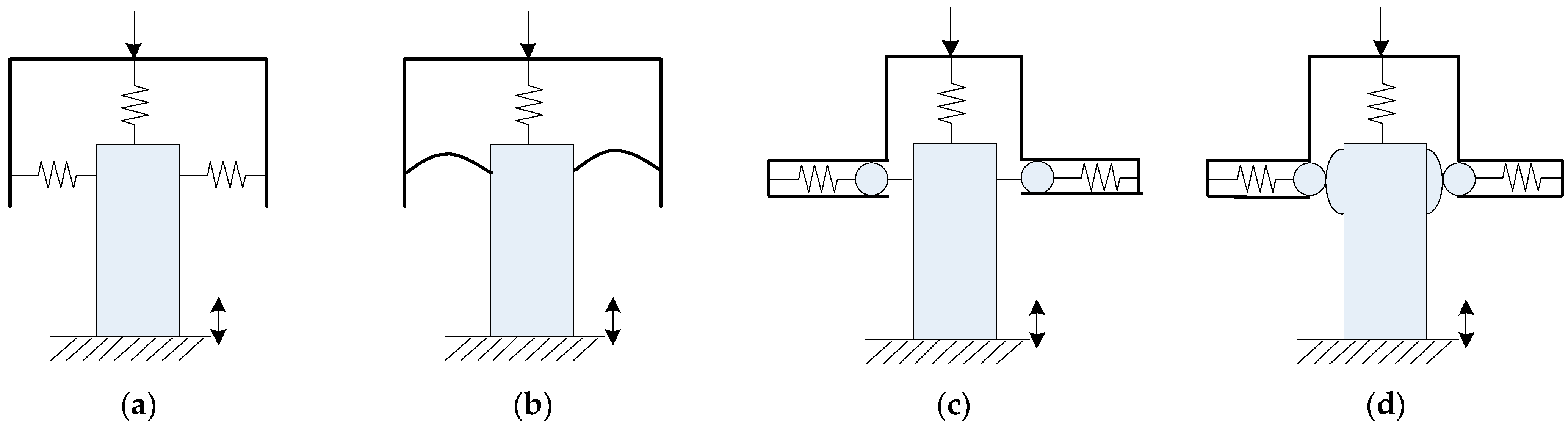
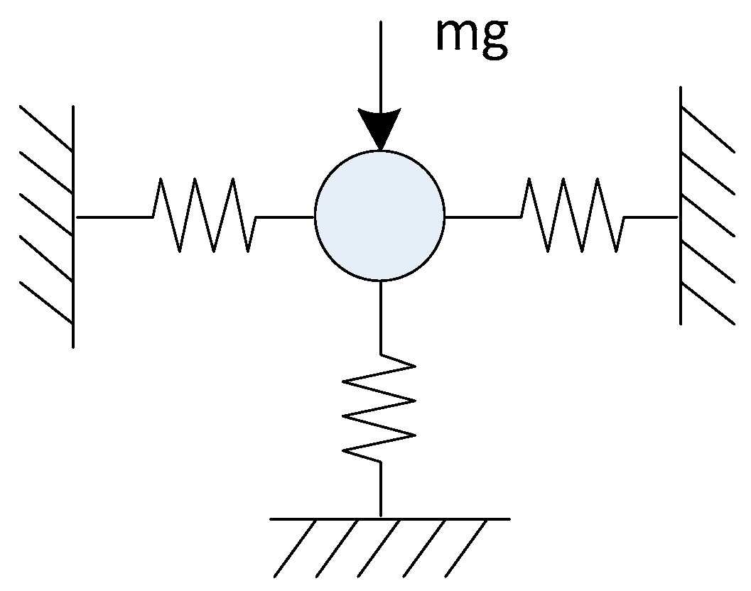
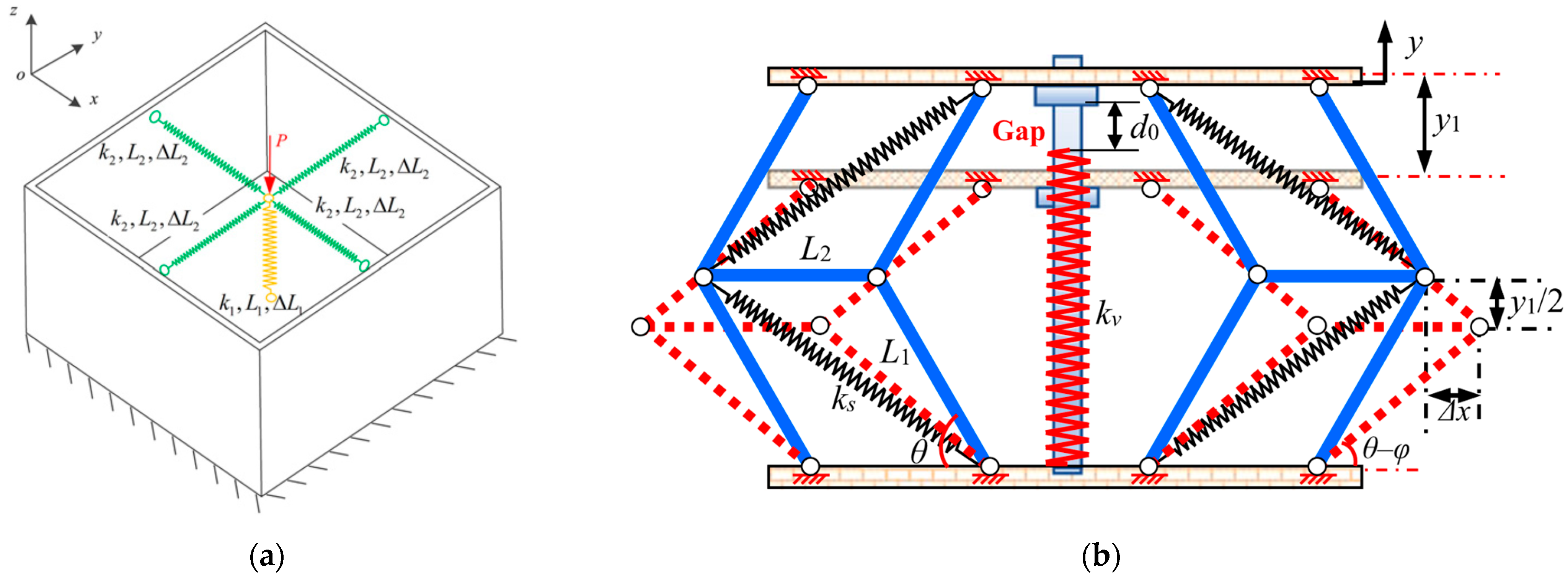
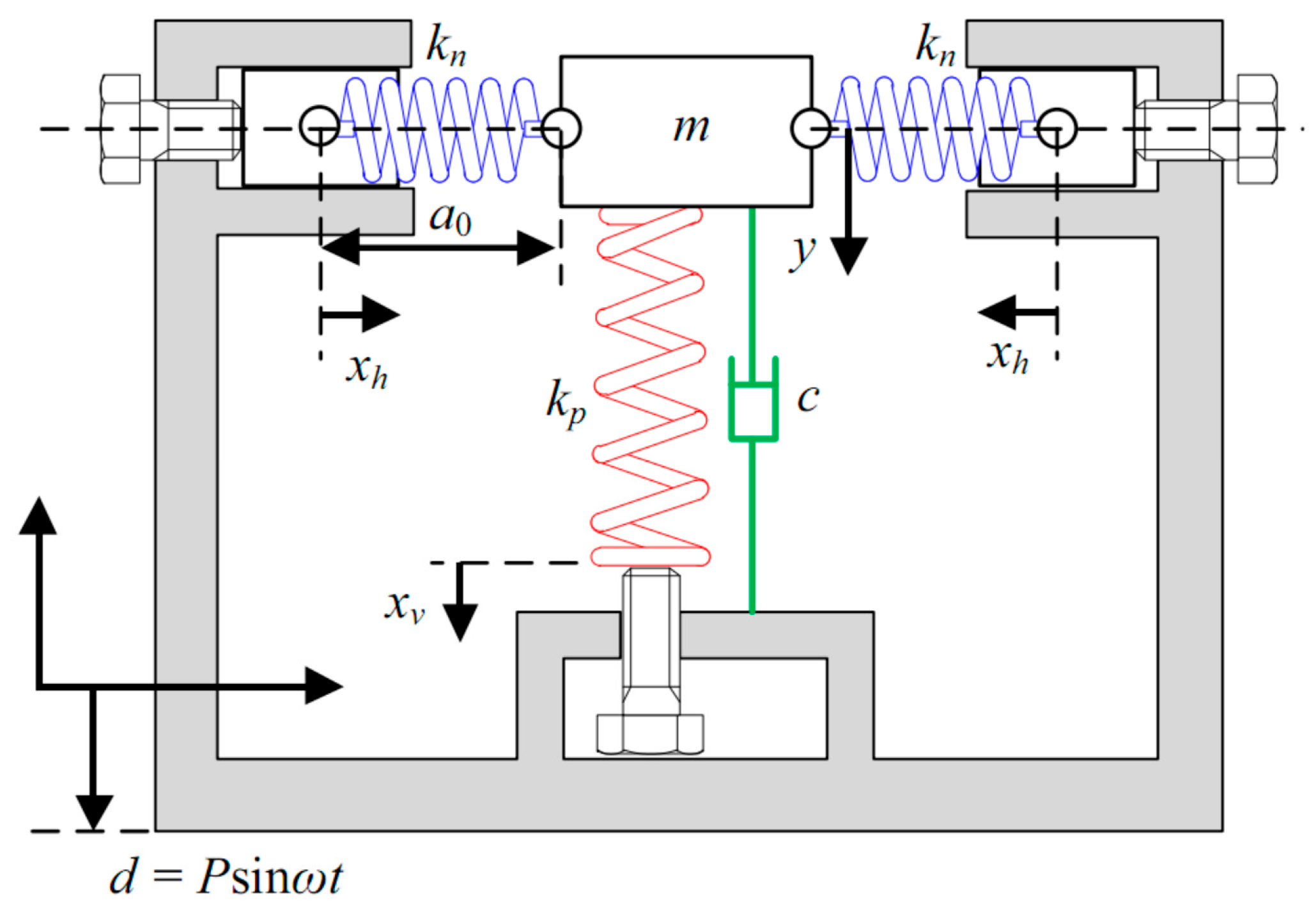
2.2.1. Linear Spring as Negative Stiffness Mechanism

This mechanism commonly employs inclined mechanical springs as the negative stiffness component. It is renowned for its high elastic potential energy yet exhibits a limited load-carrying capacity. Wu [35] optimized the three-spring configuration and devised a lateral-adjusting mechanism. This allows the vibration isolator to encompass a broader spectrum of vibration isolation frequencies without compromising the dimensional constraints. Consequently, it can fulfill the vibration isolation requirements across varying loading conditions.
Yisheng Zheng [36] proposed a six-degree-of-freedom QZS isolation platform constructed from six modules utilizing compressed-spring structures, as depicted in Figure 5a. The underlying QZS principles in both the translational and torsional directions are expounded upon. Upon establishment of the static model of the platform and its linearization at the static equilibrium position, it was found that linear cross-coupling effects emerge in the presence of static loads. Subsequent linearized dynamic analysis of the isolation platform revealed that through spring compression, the isolation frequency band can be extended to encompass a lower frequency range in all six directions. A novel linkage antivibration structure comprised a symmetric polygonal configuration and a vertical spring [37], as depicted in Figure 5b. Initial investigation into the static stiffness behavior unveiled the inherent positive and negative stiffness compensation mechanisms of linear springs within the symmetric polygonal structure. By fine-tuning the structural parameters, the linear spring can effectively offset the linear negative stiffness of the symmetric polygonal structure, thereby achieving enhanced quasi-zero stiffness characteristics over a broader stroke. To mitigate the spring-back behavior of conventional flexure hinges, a positive and negative stiffness matching method was employed [38]. The spring four-bar linkage (4BSL) was engineered as a negative stiffness rotation mechanism, while the inner and outer rings of the flexure hinge (IORFH) served as positive stiffness mechanisms. Through coupling the 4BSL and the IORFH, a novel zero-stiffness flexure hinge was devised. Zhu [27] proposed a two-degree-of-freedom seismic system model based on a smooth discontinuous oscillator. The model comprised two horizontally and orthogonally oriented vibration isolators, each exhibiting stable QZS characteristics, thereby reducing the initial isolation frequency to below 0.5 Hz. Kovacic [39] investigated a vibration isolator comprising a vertical linear spring and two nonlinear inclined springs. The authors analyzed the evolution of the system from a doubly periodic bifurcation to chaotic motion through dynamics analysis. They ascertained the frequency of the initial doubly periodic bifurcation through both approximate analysis and numerical simulation, alongside calculating the damping and other system parameters. Zuo Song [40] proposed a quasi-zero stiffness vibration isolator featuring a branch cam-roller mechanism comprising three springs to mitigate the challenge of transmitting the large-amplitude excitation induced by circular cams. The dynamic response of the vibration isolator was scrutinized and validated under harmonic and shock excitation utilizing the fourth-order Runge–Kutta method. While this vibration isolator was tailored for isolating vibrations at specific frequencies rather than random vibrations, it significantly reduced the maximum stiffness by a factor of 10 compared to its predecessor. This classification was based on the system’s reliance on the linear spring for the primary negative stiffness effect, with the cam-roller mechanism acting to support this structure rather than serving as the primary source of negative stiffness.
The design of the QZS vibration isolation system, employing a three-spring structure, exhibits notable shortcomings. This susceptibility arises when the system is subjected to substantial loads due to the unconstrained trajectories of the linear springs. Moreover, friction occurring at the joints diminishes the isolation zone, thereby impacting the system’s isolation performance.

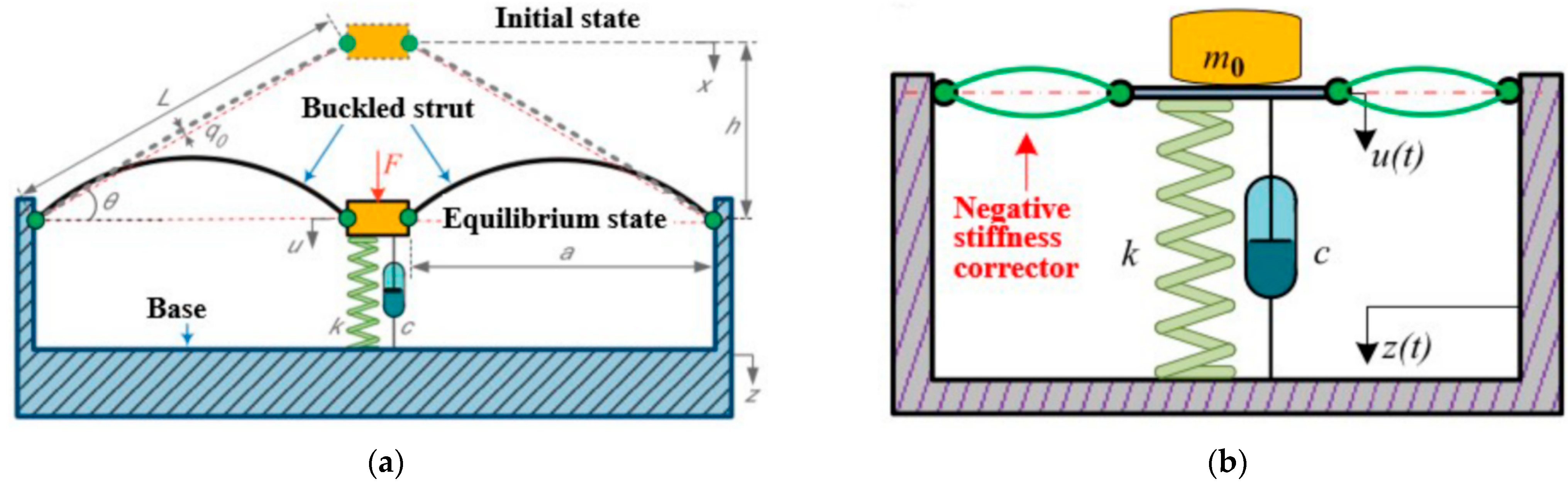
2.2.2. Buckled Beam as Negative Stiffness Mechanism

Typically, this mechanism utilizes a deformed flexure beam as its negative stiffness mechanism. Its most remarkable characteristic is its compact overall structure. The performance of the mechanism significantly impacts it, leading to unstable nonlinear characteristics. Figure 6a illustrates that Liu Xingtian [41] connected a pressurized Eulerian flexure beam in parallel with a linear spring. This system exhibits zero dynamic stiffness at the equilibrium position while retaining the load-bearing capacity of the spring, thus presenting a novel approach to isolating low-frequency vibrations. Figure 6b illustrates that Bingbing Kang [42] designed a QZS unit utilizing cams, pulleys, and Euler beams. The unit adjusts the clamping angle to decrease the initial isolation frequency, thus adapting to the impact of load variation on the performance of the QZS isolator. This addresses the deficiency of unstable system isolation performance caused by load variation. NIU Fu [43] developed a novel QZS vibration isolator employing a slotted conical disc spring as its negative stiffness mechanism. They adjusted the structural parameters to broaden the displacement range of the vibration isolator near the equilibrium position. The Helmholtz–Duffing equations under overload and underload conditions have been derived, and the primary resonance response of the nonlinear system has been investigated by employing the harmonic equilibrium method. However, this system exhibits sensitivity to the external excitation amplitude and frequency, rendering it challenging to adapt to changing working conditions. Changqi Cai [44] proposed a QZS metamaterial capable of achieving an extremely low-frequency band gap. The negative stiffness unit of the metamaterial comprises flexural beams. The elliptic integration method was employed to forecast the negative stiffness trend of flexural beams under significant deformation. The minimum band gap frequency can descend to 20 Hz, rendering it a feasible solution for filtering or attenuating extremely low-frequency waves via theoretical and simulation analyses.

2.2.3. Level Spring-Link as Negative Stiffness Mechanism

Lan [45] devised a vibration isolator for automotive seat suspension, employing connecting rods and horizontal springs as its negative stiffness mechanism. The isolator possesses high static and low dynamic stiffness, leading to a broad vibration isolation frequency band and markedly superior performance compared to a corresponding linear vibration isolator. The design underwent theoretical analysis and experimental validation. Figure 7 illustrates the isolator. The authors successfully devised a pneumatic active seat suspension by connecting the vibration isolator in parallel with the actuator. They additionally developed an adaptive intelligent controller to enhance the efficiency of the vibration isolation. The test results indicate that the active seat suspension with a negative stiffness mechanism surpasses the active seat suspension lacking it. This is attributed to the incorporation of a high static and low dynamic stiffness vibration isolator and an active controller, which enable the system to more effectively suppress the chattering phenomenon.

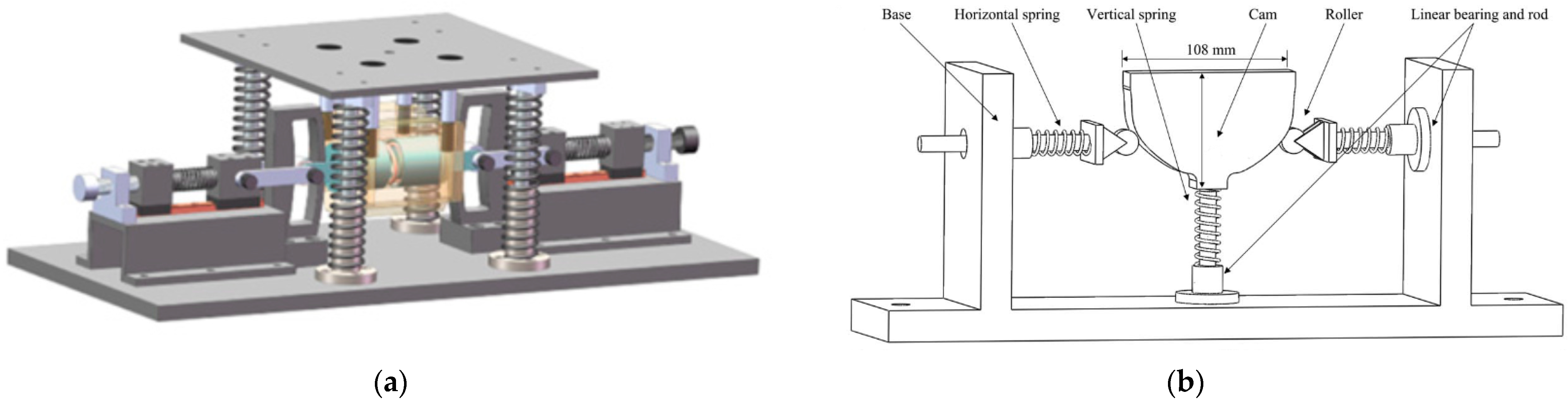
2.2.4. Cam-Roller as Negative Stiffness Mechanism

The vibration isolation system, employing either a pair of oblique springs or a spring-rod mechanism as a negative stiffness component, demonstrates high-static but low-dynamic-stiffness characteristics, often exhibiting a nonlinear jump phenomenon under light system damping and large excitation amplitudes. The jump phenomenon can be mitigated by adjusting the end trajectories of these springs or rods. To address this issue, Yonglei Zhang [46] introduced a vibration isolation system featuring a cam-roller–spring-rod mechanism, along with detailed numerical and experimental studies examining the mechanism’s impact on vibration isolation performance. Ming Li [47] introduced a QZS isolator featuring a cam-based negative-stiffness mechanism. The cam utilizes a user-defined noncircular profile to generate negative stiffness, offsetting the positive stiffness of the vertical spring and achieving QZS behavior near the equilibrium position. In contrast to earlier studies, the proposed QZS isolator offers a significant advantage: the desired cubic restoring force can be directly achieved through a meticulously crafted cam profile within the negative-stiffness mechanism, accounting for friction during the model design. This approach sidesteps the approximation errors inherent in theoretical design based solely on Taylor expansions and assumptions neglecting friction. Yuhui Yao [48] introduced a novel design for a high-static, low-dynamic-stiffness (HSLDS) isolator featuring an adjustable cam profile. This isolator utilizes the interaction force between the cam and roller to provide negative stiffness, while a linear spring contributes positive stiffness within the HSLDS system. The various structures of the cam-roller as negative stiffness mechanisms proposed by these studies are illustrated in Figure 8.

2.3. Several Types of Negative Stiffness Actuator

Negative stiffness actuators commonly employ springs, pneumatic cylinders, piezoelectric ceramics, and various other components as actuation mechanisms. Control over the output force or displacement is achieved by manipulating the parameters of these components, including the spring stiffness, pneumatic cylinder pressure, and piezoelectric ceramics voltage. Such actuators are rooted in smart material technologies, exemplified by magnetorheological fluids, capable of altering their physical characteristics in response to external factors such as magnetic and electric fields. Within engineering applications, negative stiffness actuators are deployed to attain flexible control over the output force or displacement. It is imperative to recognize that the fundamental essence of all negative stiffness actuators lies in their utilization of flexible components. The following types are commonly used in engineering environments.

2.3.1. Air Spring as Negative Stiffness Actuator

This mechanism represents an innovative elastic vibration isolation mechanism, leveraging the compressibility of air within a sealed airbag. This mechanism necessitates the reservation of a predetermined amount of energy in advance and exhibits prompt responsiveness to changes in load-bearing. Thanh [49] introduced a pneumatic active vibration isolation system designed for low-excitation frequencies. This system employs a radial basis function neural network model to determine the optimal gain of the auxiliary controllers, thereby mitigating the vibration and jitter phenomena during the control process.
Atindana [50] introduced the design and optimization of a pneumatic vehicle seat suspension system aimed at enhancing driver comfort in off-road vehicles, employing the negative stiffness structure illustrated in Figure 9a. The seat system consists of a pair of double-acting pneumatic linear actuators installed in front and behind a centralized pneumatic spring. Figure 9b illustrates the analysis of the dynamic response of a pneumatic QZS vibration isolator utilizing a wedge mechanism, as presented by Phuong et al. [51]. Adjusting the load achieved the objective of modifying the dynamic stiffness of the system. The study revealed that the QZS vibration isolator demonstrates complex dynamic responses and a phenomenon of multi-solution coexistence when analyzing the dynamics with the fifth-order Runge–Kutta algorithm. This study offered a novel concept for the design of vibration isolation mechanisms. An [52] conducted an analysis of the dynamics of the pneumatic QZS vibration isolator under overload conditions, revealing that mass detuning leads to a more complex nonlinear response of the QZS isolator, which becomes increasingly sensitive to changes in the external excitation frequency, amplitude, and damping ratio. This study enhances the precision of determining the operating frequency of the pneumatic QZS vibration isolator and presents a novel approach for designing the subsequent structure of the pneumatic QZS vibration isolator, contributing to advancements in the field of vibration isolation technology.
The QZS vibration isolator, designed with air springs, demonstrates effective vibration amplitude reduction, avoidance of system resonance intervals, friction reduction resulting from linear spring articulation, and enhanced adjustability and controllability of negative stiffness to some degree. Nevertheless, air springs are plagued by drawbacks such as poor airtightness, restricted mounting options, and the necessity of an additional power unit for active control, factors that have constrained the widespread adoption of air-spring-type QZS vibration isolators in engineering applications.

2.3.2. Disc Spring as Negative Stiffness Actuator

The QZS vibration isolation system, incorporating disc springs as negative stiffness actuators, is particularly well-suited for deployment in environments characterized by constrained axial space and demanding load conditions. Liu [53] accomplished the conversion between positive and negative stiffness by leveraging the shape memory characteristics of epoxy shape memory polymers, significant return deformation properties, thin-shell theory, and viscoelasticity theory, exploiting the negative stiffness attributes of disc springs. Figure 10a illustrates the study conducted by Meng Lingshuai [54] on the QZS isolator model employing disc springs of uniform and varying thicknesses. The authors resolved the system’s response under varying excitations, scrutinized the impacts of parameters such as the excitation amplitude and damping ratio on the system’s transmissibility, and confirmed that the QZS isolator design employing disc springs surpasses the linear system in terms of the low-frequency line spectrum isolation capability. The issue of the pronounced longitudinal vibration in ship propulsion shaft systems was mitigated through the deployment of the disc spring QZS vibration isolator. The system’s steady-state response was computed utilizing the harmonic balance method, facilitating the determination of the nonlinear stiffness and other system parameters. This ensured that the designed vibration isolator could satisfy the requirement for low-frequency vibration isolation even under substantial loads, achieving a minimum vibration isolation frequency of 10 Hz. However, its applicability is confined to particular operational scenarios and may prove ineffective under fluctuating conditions.
A pioneering compact stiffness-modulated anti-vibration structure was devised, employing high-energy-density disc springs and volute springs as proposed by Kangfan Yu [55] in Figure 10b. By incorporating advantageous nonlinear stiffness characteristics into these springs, the compact size, substantial loading capacity, and exceptional vibration isolation performance of the proposed anti-vibration structure can be achieved.
Disc springs provide numerous advantages, such as robust resistance to deformation and load impact, along with effective vibration isolation capabilities. Nonetheless, their uniform design structure may lead to significant size discrepancies, posing challenges in terms of ensuring design precision. Moreover, their limited elasticity constrains their utility in various projects.

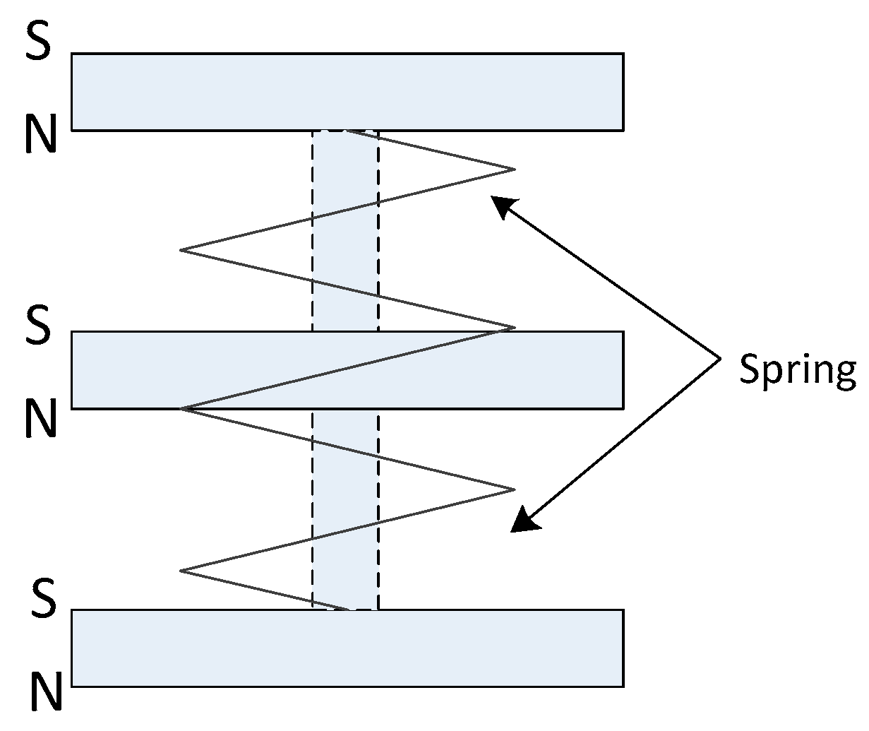
2.3.3. Magnetic Spring as Negative Stiffness Actuator

This mechanism employs permanent magnets or electromagnets as actuators for negative stiffness. Negative stiffness characteristics are attained by incorporating cams or other mechanical devices into the structural configuration. Its notable characteristic lies in the requirement to counterbalance or diminish the system response force by utilizing self-generated force. This imposes greater demands on the materials and structure. Yan Baiyi employed three permanent magnets with opposite poles to achieve negative stiffness, resulting in a reduction in the static equilibrium position at the intrinsic frequency. Magnetic springs utilize the repulsive or attractive forces between magnets to achieve negative stiffness. They are often used in applications where non-contact force transmission is desirable. For example, Alabuzhev et al. [32] studied the dynamic behavior of magnetic springs and their potential in vibration isolation systems. Magnetic springs offer the advantage of tunable stiffness characteristics by varying the distance or orientation of the magnets. This tunability allows for precise control of the system’s dynamic response, making them suitable for a wide range of vibration isolation applications. Additionally, magnetic springs can be combined with other mechanical elements to create hybrid systems that further enhance their performance. Nevertheless, the load on the vibration isolation system significantly affects the vibration isolation effectiveness, rendering it insufficient for low-frequency overload situations. Figure 11 illustrates a novel semi-active electromagnetic quasi-zero stiffness (SEQZS) vibration isolator proposed by Ma Zhaozhao [56]. The vibration isolator is designed to broaden the bandwidth of low-frequency or ultra-low-frequency vibration isolation. The article meticulously derives the theoretical equations for both static and dynamic analyses of the SEQZS vibration isolator under harmonic excitation and conducts parametric analyses to offer design insights. Furthermore, a prototype is fabricated, and the design concept is experimentally validated. The experimental results validate the theoretical formulations and illustrate that the vibration isolation performance of the proposed SEQZS vibration isolator significantly surpasses that of the corresponding linear isolator.
Figure 12 illustrates the proposed concept for an adjustable negative stiffness spring (SMNS) based on Maxwell normal stress, as introduced by Yuan [57]. This spring enhances the adjustable stiffness range and energy utilization efficiency through a newly devised magnetic circuit. Additionally, this electromagnetic negative stiffness device boasts the advantages of being frictionless, springback-free, compact, and easily controllable. The paper introduces an electromagnetic force analysis model based on magnetic circuit analysis and conducts parametric analysis. A high-static, low-dynamic-stiffness isolator is fabricated by connecting the SMNS in parallel with a linear vibration isolator. The experimental results demonstrate that the SMNS yields real-time adjustable negative stiffness, broadens the isolation bandwidth, and markedly enhances the vibration isolation performance. This study proposes an innovative solution to enhance the performance of low-frequency vibration isolation and expand the isolation bandwidth. This is of considerable significance in the realm of vibration isolation technology.
Jiang Youliang [58] devised a hybrid magnetic-air QZS vibration isolation system. The system employs an electromagnetic spring to supply negative stiffness and a vertically positioned air spring as a positive stiffness mechanism. The control theory for the magnetic-air hybrid QZS vibration isolation system is innovated with the utilization of a type-2 fuzzy controller. This ensures the vibration isolation system exhibits satisfactory QZS characteristics under a static load. Zhou [59] engineered a vibration isolator featuring high-static and low-dynamic stiffness. The isolator employs a hybrid structure consisting of an electromagnet and a permanent magnet to furnish negative stiffness. The study explores the optimal parameters to attain the optimal isolation effect and subsequently optimizes the system model. Zhou engineered a vibration isolator featuring high-static and low-dynamic stiffness. The isolator employs a hybrid structure consisting of an electromagnet and a permanent magnet to furnish negative stiffness. The polarity of the electromagnet can be controlled to regulate the stiffness of the structure by adjusting the current. The optimal parameters of the electromagnetic spring are investigated to achieve the optimal vibration isolation effect. The system model is optimized using the optimal parameters, and the mathematical relationship between the excitation force frequency and the displacement transfer rate is calculated. Ultimately, experiments demonstrate the excellent vibration isolation performance and real-time adjustment capability of this vibration isolator. Yan [60,61] introduced a novel passive vibration isolator that furnishes both magnetic repulsion and suction. They formulated a nonlinear equation for calculating the magnetic force, deduced a fitting expression for the equivalent nonlinear magnetic stiffness, and experimentally validated that magnetic repulsion and suction fulfill the vibration isolation requirements across various bandwidths. Sun [62] pioneered a new electromagnetic negative-stiffness spring employing a permanent ring magnet and a coil with a rectangular cross-section. They have established and experimentally corroborated this novel spring type utilizing the thin-wire method. An ENSS analytical model is formulated and experimentally corroborated employing the thin-wire method. The model quantitatively explores the factors influencing the electromagnetic force and stiffness characteristics. The correlation between the excitation frequency and the force transfer rate under varying currents is examined, and real-time adjustment of negative stiffness is accomplished. The magnetic-type negative stiffness mechanism boasts several advantages, encompassing a compact structure, rapid response, high static load-bearing capacity density, minimal loss, and minimal environmental requirements. Nevertheless, it can prove challenging to control during operation and is significantly influenced by the current and magnetism, with its nonlinear characteristics being unstable.

3. Magnetic Negative Stiffness in QZS Isolators

3.1. Introduction to Magnetic Negative Stiffness

Magnetic negative stiffness is a phenomenon arising from magnetic fields and is frequently harnessed in control systems to attain adaptable force or displacement regulation. The system consists of a mobile magnet and a stationary magnet, with the stiffness characteristics modifiable by adjusting the intensity or orientation of the magnetic field. The magnetic negative stiffness system functions based on the interaction force between magnets. When two magnets are close together, they generate an attractive force; conversely, when they are distant, a repulsive force arises. This interaction force dictates the stiffness characteristic of the system, which is modifiable by varying the intensity or direction of the magnetic field. This facilitates control over the output force or displacement. In a magnetically negative stiffness system, the mobile magnet usually encompasses a magnetized movable component, whereas the fixed magnet is affixed to the remaining system components. The negative stiffness characteristics of the system can be modified by adjusting the distance, angle, or magnetic field strength between the mobile and fixed magnets.
Primarily, these systems afford an extensive adjustable range and exceptionally precise control, enabling exceedingly delicate force or displacement regulation through manipulation of the magnetic field’s strength or orientation. They exhibit rapid response times, facilitating high-frequency vibration control. Additionally, they boast low energy consumption, frictionlessness, and a prolonged lifespan. Magnetic negative stiffness systems find wide application across numerous fields. In robotics [63,64], they can facilitate adaptable force control to accommodate diverse environmental conditions and task specifications. In aerospace applications [65], they can mitigate aircraft vibrations and enhance flight stability. In automotive engineering [66], they can serve in vibration damping or suspension systems, thereby enhancing the driving comfort. These systems also find extensive applications in medical equipment, precision positioning control, and various other domains. By varying the strength or direction of the magnetic field, one can attain flexible and precise control to cater to the requirements of diverse fields.

3.2. Mathematical Modeling of Permanent Magnet Negative Stiffness Elements

3.2.1. Mechanical Modeling of Magnetic Springs with Negative Stiffness of Magnetic Rings

Figure 13 depicts the permanent magnet ring structure frequently employed in engineering applications encompassing magnetic bearings, gears, and couplings. The permanent magnet bearing harnesses the force between two permanent magnets as a supporting force. It can be categorized into radial and axial permanent magnet structures, contingent upon the magnetization orientation of the magnets and the distinct manifestations of the magnetic force. Figure 14 delineates the diverse configurations attainable contingent upon the varying types.
Initially, the negative stiffness spring, comprised of the axially magnetized magnetic ring, undergoes mechanical analysis. The established theoretical analysis model, illustrated in Figure 14a and Figure 15, is employed as an exemplar to analyze the magnetic force acting on the inner magnetic ring end face 2 and the outer magnetic ring end face 3.
The magnetic charge of the point P on the end face 2 of the inner magnetic ring is:
q 2 = σ r 2 d α d r 2
where r 2 and α are the polar coordinates of any point P on the end face 2 of the inner magnetic ring; σ is the surface density of the magnetic charge on the end face of the ring, assuming that the magnetic charge is uniformly distributed on the end face. According to the theory of electromagnetism, it can be seen that the outer magnetic ring end face 3 at point Q by the P point of the electromagnetic charge generated by the magnetic field strength is:
H = 1 4 π μ 0 q 2 r 2 r 0
where μ 0 is the vacuum permeability; r is the separation between points P and Q on end face 2 and end face 3; and r 0 is the unit direction vector between points P and Q. Therefore, the magnetic force on the point charge at point Q is:
d F = H q 3 = H σ r 3 d β d r 3 = σ 2 4 π μ 0 r 2 r 3 d α d β d r 2 d r 3 r 3 r
where r 3 and β are the polar coordinates of a point Q on the end face 3 of the outer ring. According to the theoretical equation of static magnetism, it is shown as follows:
σ = j n = μ 0 M n B = μ 0 ( H + M )
where j is the magnetic polarization intensity vector; n is the unit vector in the direction normal to the end face of the magnetic ring. M represents the magnetic induction intensity. When H = 0 , B = B r , so B r = μ 0 M . Since the magnetization direction of the magnetic ring is axial magnetization, which coincides with the normal direction of the end face of the ring, the combined above equations can be obtained:
σ = μ 0 M = B r
where B r is the residual magnetic induction. Therefore, Equation (3) can be expressed as:
d F = B r 2 4 π μ 0 r 2 r 3 d α d β d r 2 d r 3 r 3 r = C r 2 r 3 d α d β d r 2 d r 3 r 3 r
where C = B r 2 4 π μ 0 is the coefficient related to the magnetic properties of the permanent magnet material. By taking Equation (6) and projecting it along the X-direction as shown in Figure 15a, the axial force along the end face of the ring generated by the point magnetic charge at any point P on end face 2 and any point Q on end face 3 is obtained:
d F 32 = C r 2 r 3 d α d β d r 2 d r 3 r 3 r i
where i is the unit vector in the axial X-coordinate direction of the magnetic ring. From Figure 15b, the geometrical relationship between point P and point Q can be established, then
r = r x 1 = r 3 r 2 x 1
where x 1 is the relative axial displacement between the inner and outer ring end surfaces 2, 3. The unit vectors in the axial coordinate direction of the magnetic ring form angles γ and φ with the x-axis and y-axis, respectively. Substituting equation r i into, we can obtain
r i = r 3 i r 2 i x 1 i
Due to
r 3 i = r 3 sin γ r 2 i = r 2 sin φ x 1 i = x 1
So, Equation (9) can be further simplified as
r i = r 3 sin γ r 2 sin φ x 1
where sin γ = x 1 r 3 2 + x 1 2 ,   sin φ = x 1 r 2 2 + x 1 2 . Also, based on the geometrical relationship between point P and point Q, we can obtain:
r = x 1 2 + ( r 3 cos β r 2 cos α ) 2 + ( r 3 sin β r 2 sin α ) 2
By substituting Equations (11) and (12) into Equation (7) and integrating over the entire end face thereof, the magnitude of the magnetic force acting along the axial direction of the magnetic ring between the end face 2 of the inner ring and the end face 3 of the outer ring can be obtained as follows:
F 32 = C R 1 R 2 R 3 R 4 0 2 π 0 2 π ( r 3 sin γ r 2 sin φ x 1 ) r 2 r 3 d r 2 d r 3 d α d β [ x 1 2 + ( r 3 cos β r 2 cos α ) 2 + ( r 3 sin β r 2 sin α ) 2 ] 3 2
Similarly, the magnitude of the magnetic force between the other end faces of the inner and outer rings along the axial direction of the ring can be obtained as the magnitude of the partial force:
F 31 = C R 1 R 2 R 3 R 4 0 2 π 0 2 π ( r 3 sin γ r 1 sin φ x 1 ) r 1 r 3 d r 1 d r 3 d α d β H 1 + x 1 2 + r 3 cos β r 1 cos α 2 + r 3 sin β r 1 sin α 2 3 2
F 41 = C R 1 R 2 R 3 R 4 0 2 π 0 2 π ( r 4 sin γ r 1 sin φ x 1 ) r 1 r 4 d r 1 d r 4 d α d β [ x 1 2 + ( r 4 cos β r 1 cos α ) 2 + ( r 4 sin β r 1 sin α ) 2 ] 3 2
F 42 = C R 1 R 2 R 3 R 4 0 2 π 0 2 π ( r 4 sin γ r 2 sin φ x 1 ) r 2 r 4 d r 2 d r 4 d α d β [ ( H 2 x 1 ) 2 + ( r 4 cos β r 2 cos α ) 2 + ( r 4 sin β r 2 sin α ) 2 ] 3 2
where H 1 , H 2 is the axial height of the inner and outer ring; r 1 , r 2 is the inner and outer radius of the inner ring; r 3 , r 4 is the inner and outer radius of the outer ring. The internal and external magnetic ring along the axial load-bearing force should be the superposition of the magnetic action between the end faces of the internal and external magnetic ring, having a positive and negative sign according to the two interacting end faces of the magnetic charge division, with the same number of magnetic charge is positive and the opposite number of magnetic charge is negative, that is:
F = F 41 + F 32 F 31 F 42
From the definition of stiffness, the stiffness equation for a negative stiffness magnetic spring constructed from the inner and outer rings is obtained as:
K N = d F d x 1
The negative sign in the formula indicates that the direction of the restoring force of this negative stiffness magnetic spring is opposite to the direction of the axial load-bearing force generated by the inner and outer magnetic rings.

3.2.2. Mechanical Modeling of Rectangular Magnet Negative Stiffness Springs

Accurately calculating the magnetic force of permanent magnets is crucial for establishing a magneto-negative stiffness model for rectangular permanent magnets. Extensive research has been conducted in this area. In 1984, Yonnet [67] proposed an analytical model based on the surface charge model for calculating the magnetic force of a three-dimensional rectangular permanent magnet with parallel magnetization directions. This model was derived by considering the differential of the magnetic interaction energy concerning displacements. It accurately computes the interaction force and moment between two permanent magnets with parallel magnetization directions, facilitating the design and optimization of magnetic parameters. Additionally, Yonnet derived a three-dimensional force and moment model for two rectangular permanent magnets with perpendicular magnetization directions. Bancel [68] introduced the concept of a magnetic node and developed a highly accurate three-dimensional analytical model for the magnetic field and force of a rectangular permanent magnet based on this concept, suitable for designing and optimizing magnetic parameters. However, recent years have witnessed an in-depth exploration of the negative stiffness structure. The magnetic negative stiffness structure offers a promising alternative to conventional mechanical structures, characterized by its compact design, efficient space utilization, and absence of mechanical friction, rendering it particularly suitable for precision equipment. Rectangular or ring-shaped permanent magnetic materials serve as elastic support structures to provide gravitational or repulsive forces in mechanical vibration applications, with effective arrangements implemented to mitigate the influence of nonlinear permanent magnetic materials. The magnetic force exerted by the rectangular permanent magnetic materials below is computed.
Figure 16 illustrates a structure featuring magnetically repulsive negative stiffness. Three magnets are vertically arranged, with the upper and lower magnets firmly affixed to the ground. The magnetization direction of all three magnets is aligned. When the middle magnet undergoes horizontal displacement from its equilibrium position, it experiences a combined force from the upper and lower magnets in the same direction, propelling it further from the equilibrium position, thus demonstrating negative stiffness characteristics. Similarly, the vertical movement of the middle magnet results in its restoration to the equilibrium position due to the repulsive force, leading to the manifestation of positive stiffness characteristics within the system. The aforementioned analysis elucidates that both magnetic suction and magnetic repulsion arrangements can yield negative stiffness characteristics, contingent upon the control of the intermediate magnet’s movement direction.
The magnetic force between permanent magnets is dictated by the magnetic field they generate. This field is influenced by multiple factors, encompassing the dimensions of the magnets, the magnetic material employed, the degree of magnetization, and the spatial configuration of the magnets. Consequently, when modeling magnetic force, it is imperative to account for distinct parameters such as the magnet size, geometry, and inter-magnet positioning.
The analysis of the magnetic force expression between two rectangular permanent magnets is conducted. Additionally, the mathematical model for negative stiffness in a three-magnet structure is formulated. As illustrated in Figure 17, two rectangular magnets, denoted as M1 and M2, exhibit rigidity and homogeneity. They are aligned parallel to the 2c side and possess uniform magnetic densities denoted as σ and σ in their upper and lower planes, respectively. It is assumed that the dimensions are ( 2 a , 2 b , 2 c ) and ( 2 a , 2 b , 2 c ) for M1 and M2, and that the magnetization strengths of each magnet are denoted as J and J , respectively, with the two magnets magnetized in opposite directions. This magnetic charge density can be expressed as:
σ = J · N
At this time, the upper and lower relative two planes 2 a × 2 b and 2 a × 2 b , and the upper and lower planes have a uniform magnetic density σ and σ , then the upper and lower two permanent magnets in the vertical direction of the static magnetic energy can be expressed as:
E = a a d x b b d y a a d x b b d y J J 4 π μ 0 r
where r = ( α + a a ) 2 + ( β + y y ) 2 + γ 2 .
The quadratic integration of the above equation can be expressed as:
E = J J 4 π μ 0 i = 0 1 j = 0 1 k = 0 1 l = 0 1 p = 0 1 q = 0 1 ( 1 ) i + j + k + l + p + q ϕ ( μ i j , ν k l , ω p q , r )
where
ϕ ( μ , ν , ω , r ) = 1 2 μ ( ν 2 ω 2 ) ln ( r μ ) + 1 2 ν ( μ 2 ω 2 ) ln ( r ν ) + μ ν ω   arctan μ ν r ω + r 6 ( μ 2 + ν 2 2 ω 2 )
μ i j = α + ( 1 ) j a ( 1 ) i a ν k l = β + ( 1 ) l b ( 1 ) k b ω p q = γ + ( 1 ) q c ( 1 ) p c r = μ i j 2 + ν k l 2 + ω p q 2
According to the principle of the equivalent magnetic charge model, the interaction force F between the two permanent magnets can be obtained along the X, Y, and Z directions, respectively, as:
F x = J J 4 π μ 0 i = 0 1 j = 0 1 k = 0 1 l = 0 1 p = 0 1 q = 0 1 ( 1 ) i + j + k + l + p + q φ x ( μ i j , ν k l , ω p q , r ) F y = J J 4 π μ 0 i = 0 1 j = 0 1 k = 0 1 l = 0 1 p = 0 1 q = 0 1 ( 1 ) i + j + k + l + p + q φ y ( μ i j , ν k l , ω p q , r ) F z = J J 4 π μ 0 i = 0 1 j = 0 1 k = 0 1 l = 0 1 p = 0 1 q = 0 1 ( 1 ) i + j + k + l + p + q φ z ( μ i j , ν k l , ω p q , r )
where
φ x ( μ i j , ν k l , ω p q , r ) = ν 2 ω 2 2 ln ( r μ ) + μ ν ln ( r ν ) + ν ω arctan μ ν r ω + r μ 2 φ y ( μ i j , ν k l , ω p q , r ) = μ 2 ω 2 2 ln ( r ν ) + μ ν ln ( r μ ) + ν ω arctan μ ν r ω + r μ 2 φ z ( μ i j , ν k l , ω p q , r ) = μ ω ln ( r μ ) ν ω ln ( r ν ) + μ ν arctan μ ν r ω r ω
From the principle of virtual work, it can be seen that in the Z direction, the magnetic force on the permanent magnet can be derived to obtain its stiffness as:
K ( z ) = d F z d z = J J 4 π μ 0 i = 0 1 j = 0 1 k = 0 1 l = 0 1 p = 0 1 q = 0 1 ( 1 ) i + j + k + l + p + q θ z ( μ i j , ν k l , ω p q , r )
where
θ z ( μ i j , ν k l , ω p q , r ) = 2 r + μ ln ( r μ ) + ν ln ( r ν )

3.2.3. Mechanical Modeling of Wedge-Shape Magnet Negative Stiffness Springs

Figure 18 shows the three-dimensional and top view of the wedge-shaped permanent magnet, with the magnetization direction indicated as OO1. The magnetic force between the surface unit dSi and the surface unit dSj can be expressed as follows:
dF = μ 0 4 π σ i σ j ( p j p i ) | p j p i | 3 dS i dS j
where p i and p j are the position vectors of the face units d S i and d S j , respectively, and σi is the electro-helicity density of the face i (i = 1, 2, 3, 4). Assuming that the rooted permanent magnet is an ideal model and is uniformly magnetized, the magnetic charge densities of the faces 5 and 6 are zero, whereas that of the other faces can be expressed as:
σ 1 = J μ 0 ( cos α c o s β + sin α s i n β ) σ 2 = J μ 0 ( cos α c o s β + sin α s i n β ) σ 3 = σ 4 = J μ 0 sin θ
where β is the angle between the y-axis and p i , J = B r . Thus the component of dF in the Z direction can be expressed as:
dF z = μ 0 4 π σ i σ j ( h 1 h 2 ) | p j p i | 3 dS i dS j
where h 1 and h 2 are the components of p i and p j in the Z direction, respectively.
Figure 19 shows a pair of wedge-shaped permanent magnets P M M and P M b magnetized in the radial direction, and the magnetic force between the P M M and P M b surface cells can be obtained according to Equation (28). The magnetic force between face 1 of permanent magnet P M M and face 1 of P M b can be expressed as follows:
F M 1 b 1 z = μ 0 4 π σ M 1 σ b 1 ( h 1 h 2 ) | p b 1 p M 1 | 3 dS b 1 dS M 1 = μ 0 4 π M t M H + L M L b L b α M θ M α M + θ M α b θ b α b + θ b α M 1 α b 1 ( h 1 h 2 ) | p b 1 p M 1 | 3 ( R 1 + T 1 ) ( R 2 + T 2 ) d h 1 d h 2 d β 1 d β 2
where
σ M 1 = J μ 0 cos α M cos β M + sin α M sin β M σ b 1 = J μ 0 cos α b cos β b + sin α b sin β b p b 1 p M 1 2 = ( R 1 + T 1 ) 2 + ( R 2 + T 2 ) 2 2 ( R 1 + T 1 ) ( R 2 + T 2 ) cos ( β 2 β 1 ) + ( h 1 h 2 ) 2
Deriving F M 1 b 1 z with respect to H , the magnetic stiffness is given by
K M 1 bl ( H ) = dF M 1 bl z dH = μ 0 2 π ( L b L b α M θ M α M + θ M α b θ b α b + θ b σ M 1 σ b 1 ( h 1 h 2 ) | p b 1 p M 1 | 3 ( R 1 + T 1 ) ( R 2 + T 2 ) d h 2 d β 1 d β 2 ) H + L M H L M
Similarly, the magnetic force F M 0 and the magnetic stiffness K M i b j z between the other surfaces can be obtained, so the total magnetic force and magnetic stiffness between the two magnets along the Z direction component can be expressed as
F Mb 2 = i = 1 4 j = 1 4 F Mibj z
K Mb z = i = 1 4 j = 1 4 K M i b j z

3.3. Mathematical Modeling of Electromagnetic Negative Stiffness Elements

Owing to its hysteresis and magnetic saturation characteristics, the energized coil is typically wound around ferromagnetic material to constitute an electromagnetic spring. In contrast, permanent magnets are incapable of further magnetization. The magnetic field of the negative stiffness device results from the combination of the magnetic fields generated by the permanent magnet and the coil. The calculation of the magnetic force exerted by the electromagnetic negative stiffness device can be partitioned into two components: the repulsive force between the center permanent magnet and the left and right permanent magnets, and the electromagnetic force induced by the helical coil acting upon the left and right permanent magnets.
In accordance with the equivalent magnetic charge theory, the interaction between magnets is determined by their geometric configuration and relative positioning. This assumption entails approximating the permanent magnet structure as a coaxial cylindrical magnet. Given that the material and geometric parameters of the permanent magnets on both sides are identical, we illustrate the repulsive force between the magnets on the right side as an exemplar. Figure 20 elucidates the relative positional dynamics between the magnets. The middle magnet has a radius of R 1 and a length of l 1 , with a magnetic charge surface density of σ 1 on pole surfaces 1 and 2; the right magnet has a radius of R 2 and a length of l 2 , with a magnetic charge surface density of σ 2 on pole surfaces 3 and 4. The coordinate origin is established at the center of the permanent magnet. Furthermore, the relative displacement between the magnets is denoted by y 0 , with the coordinate origin located at the geometric center of the middle permanent magnet. The surface area at a point A on pole surface 1 of the middle permanent magnet can be denoted as r 1 d r 1 d α , with a magnetic charge of q A = r 1 d r 1 d α . Similarly, the surface area at a point on pole surface 3 of the right permanent magnet can be represented as r 2 d r 2 d α , with a magnetic charge of q B = r 2 d r 2 d α .
Given that the position of the intermediate permanent magnet remains fixed and magnetic charges repel each other, the micrometric magnetic force exerted by the point charge at point A on pole surface 1 toward the point charge at point B on pole surface 3 is:
d F 13 = σ 2 σ 2 4 π μ 0 r 1 r 2 d r 1 d r 2 d α d β r 13 3 r 13
where r 13 = y 0 2 + r 1 sin α r 2 sin β 2 + r 1 cos α r 2 cos β 2 .
The projection of the micrometric magnetic force d F 13 on the y-axis is:
d F 13 y = d F 13 e y = σ 2 σ 2 4 π μ 0 r 1 r 2 d r 1 d r 2 d α d β r 13 3 y 0
Ditto:
d F 14 y = d F 14 e y = σ 2 σ 2 4 π μ 0 r 1 r 2 d r 1 d r 2 d α d β r 14 3 ( y 0 + l 2 )
d F 23 y = d F 23 e y = σ 2 σ 2 4 π μ 0 r 1 r 2 d r 1 d r 2 d α d β r 23 3 ( y 0 + l 1 )
d F 24 y = d F 24 e y = σ 2 σ 2 4 π μ 0 r 1 r 2 d r 1 d r 2 d α d β r 24 3 ( y 0 + l 1 + l 2 )
where
r 14 = y 0 + l 2 2 + r 1 sin α r 2 sin β 2 + r 1 cos α r 2 cos β 2 r 23 = y 0 + l 1 2 + r 1 sin α r 2 sin β 2 + r 1 cos α r 2 cos β 2 r 24 = y 0 + l 1 + l 2 2 + r 1 sin α r 2 sin β 2 + r 1 cos α r 2 cos β 2
The total magnetic force along the y-axis is in a differential form:
d F y = σ 2 σ 2 4 π μ 0 y 0 r 13 3 + y 0 + l 1 + l 2 r 24 3 y 0 + l 2 r 14 3 y 0 + l 1 r 23 3 r 1 r 2 d r 1 d r 2 d α d β
Integrating the above equation yields:
F y = σ 2 σ 2 4 π μ 0 0 2 π 0 2 π 0 R 2 0 R 1 y 0 r 13 3 + y 0 + l 1 + l 2 r 24 3 y 0 + l 2 r 14 3 y 0 + l 1 r 23 3 r 1 r 2 d r 1 d r 2 d α d β
Understanding the magnetic field distribution of a helical coil is pivotal for analyzing the electromagnetic force exerted on a permanent magnet within its magnetic field. Consider a scenario where the energized coil has a length of L, an inner diameter of R1, and an outer diameter of R2, as illustrated in Figure 21. Let the current passing through the coil be denoted as I, the number of turns per unit length as n, and the total number of turns in the thick-walled coil as N. Initially, the analysis focuses on a single-layer coil with a radius of R, as depicted in Figure 22. Since the energized helical coil exhibits symmetry, the analysis primarily concerns the magnetic field distribution in the yOz plane, where the y-axis represents the axial component.
In the yOz plane, take any point Q ( 0 , y 0 , z 0 ) , the y-axis coordinates y at the thickness of the ring, the current in the ring for I = n I d y , in the ring on the S ( R cos θ , y , R sin θ ) point of the current element I d l .
I d l = I R sin θ d θ e x + I R cos θ d θ e z
The position vector r from the current element I d l to Q is:
r = R cos θ e x + ( y 0 y ) e y + ( z 0 R sin θ ) e z
According to Biot–Savart’s law, the magnetic induction d B produced by the current element I d l at point Q is:
d B = μ 0 4 π I d l × r r 3
where r = R 2 cos 2 θ + ( y 0 y ) 2 + ( z 0 R sin θ ) 2 .
Substituting Equations (43) and (44) into Equation (45) obtains:
d B = n μ 0 I R cos θ ( y y 0 ) e x + R ( z 0 cos θ R ) e y + R sin θ ( y y 0 ) e x 4 π R 2 cos 2 θ + ( y 0 y ) 2 + ( z 0 R sin θ ) 2 3 / 2 d y d θ
The axial component along the y-axis is then:
d B y = n μ 0 I R ( z 0 cos θ R ) d y d θ 4 π R 2 cos 2 θ + ( y 0 y ) 2 + ( z 0 R sin θ ) 2 3 / 2
Taking the dual integration of the above equation yields that the magnetic induction of a single helical coil of radius R at point Q along the axial direction as:
B y R = 0 2 π L / 2 L / 2 n μ 0 I R ( z 0 cos θ R ) d y d θ 4 π R 2 cos 2 θ + ( y 0 y ) 2 + ( z 0 R sin θ ) 2 3 / 2
From Figure 22, the number of coil turns per unit length within a thin layer of thickness d R can be expressed as:
n = N d R ( R 2 R 1 ) L
Substituting Equation (49) into Equation (48) and taking the integral, the magnetic induction of the helical coil along the axial direction at point Q is given as:
B y = 0 2 π L / 2 L / 2 R 1 R 2 N μ 0 I R ( z 0 cos θ R ) d R d y d θ 4 π R 2 R 1 R 2 cos 2 θ + ( y 0 y ) 2 + ( z 0 R sin θ ) 2 3 / 2
Assuming the uniform distribution of the magnetic field, according to Maxwell’s classical theory, the electromagnetic force acting on a permanent magnet within a known external magnetic field can be comprehended as the vector sum of the forces acting on the surface molecular currents of the permanent magnet in the magnetic field. Hence, the expression for the electromagnetic force applied to the permanent magnet is:
F M = F L + F R = B L 2 B R 2 2 μ 0 S
where F L and F B are the magnetic force at the center of the left and right surfaces of the permanent magnet, respectively; B L and B R are the magnetic induction intensity at the center of the left and right surfaces of the permanent magnet, respectively, which can be obtained by Equation (50); and S is the area of the left (right) surface of the permanent magnet. From the above analysis, the theoretical calculation model of the electromagnetic force of a negative stiffness device is:
F e = F M + F y

4. Current Progress of Magnetic Negative Stiffness in QZS Isolators

4.1. QZS-Based Permanent Magnet Negative Stiffness Elements

The utilization of permanent magnets in QZS vibration isolators has garnered significant attention from scholars in recent years, and their distinctive properties render them an optimal material for vibration isolation. With the ongoing advancement of science and technology, the investigation into QZS vibration isolators has progressively delved deeper, encompassing diverse realms ranging from fundamental theory to practical implementations.
From an academic perspective, research on the utilization of permanent magnets in QZS vibration isolators primarily centers on several key areas. Firstly, employing theoretical modeling and numerical simulation, we investigate the functional mechanisms of permanent magnets within QZS vibration isolators and explore optimization design methodologies. Secondly, we conduct a comprehensive examination of the practical implications of permanent magnets within vibration isolation systems, coupled with experimental validation, to discern the influencing factors. Additionally, we meticulously scrutinize the performance and durability of permanent magnet materials, along with potential long-term usage issues. This endeavor not only furnishes a crucial theoretical framework for the design and enhancement of QZS vibration isolators but also establishes a robust groundwork for the advancement of associated fields. Notably, the integration of permanent magnets into QZS vibration isolators has commenced practical application in various domains. For instance, in precision instrument manufacturing, QZS vibration isolators effectively mitigate the external vibration effects on instrument accuracy, thereby enhancing the measurement precision and stability. Similarly, in aerospace applications, QZS vibration isolators proficiently attenuate aircraft vibrations during flight, thus augmenting the equipment reliability and operational efficiency. Moreover, amidst escalating concerns regarding environmental noise and vibration impacts, the QZS vibration isolator, as a novel vibration isolation apparatus, harbors extensive application prospects.
Magnetic rings constitute a pivotal component of QZS vibration isolators. Extensive research endeavors have centered on the utilization of magnetic rings within negative stiffness architectures. As shown in Figure 23, the study by Dong [69] introduces an innovative passive airborne quasi-zero stiffness platform (APQZSP) comprising upper and lower planes, a vibration-resistant framework, and six QZS leg components. This configuration primarily aims to mitigate low-frequency vibrations in airborne electro-optical systems, consequently enhancing the measurement precision. The QZS leg components of the platform are fabricated through the parallel integration of folded beam springs and magnetic negative stiffness springs (MNSSs). The magnetic force and negative stiffness characteristics of the MNSSs are meticulously elucidated within the thesis, alongside a comprehensive discussion on the influence of frictional damping imparted by the seismic structure on the platform’s isolation efficacy. The study scrutinizes the platform’s isolation efficacy under frictional damping by employing the harmonic balance methodology, and it delves into the impacts of damping and excitation on said performance. The findings indicate that the adoption of the QZS technique diminishes the platform’s resonance frequency, efficaciously isolating low-frequency vibrations. Additionally, the study elucidates that frictional damping mitigates resonance by maintaining the displacement transfer rate within specified bounds when the excitation frequency falls below the isolation frequency. Furthermore, the research encompasses a comparative analysis of the isolation efficacy between platforms with and without MNSSs, showcasing the MNSSs’ capability in broadening the low-frequency isolation bandwidth and markedly enhancing the platform’s low-frequency vibration isolation performance. In conclusion, the seminal contribution of this study lies in the design of an innovative airborne optoelectronic QZS platform, markedly enhancing the low-frequency vibration isolation efficacy via its pioneering structural configuration and damping mechanism, thereby substantially bolstering the stability and measurement precision of airborne optoelectronic systems.
As shown in Figure 24, Zhao Y [70] has proposed a magnetic ring array (MRA) characterized by high-amplitude negative stiffness. This design endeavors to enhance the low-frequency performance of a heavy-duty precision micro-vibration isolator by employing axially perpendicularly magnetized magnetic rings to configure an array structure generating high-amplitude negative stiffness. The study not only advances the structural design of the magnetic ring array but also formulates an analytical model elucidating its magnetic force and stiffness, while scrutinizing the impact of geometrical parameters on stiffness for optimization purposes. The study validates the efficacy of the MRA through comparative analysis with existing vibration isolation schemes. Furthermore, the study incorporates a series of experiments to substantiate the validity of the analytical model and evaluate the performance of the MRA. The experimental findings reveal that the integration of the MRA diminishes the natural frequency of the vibration isolation experimental set-up from 4.75 Hz to 1.13 Hz and attenuates the peak of the one-third octave band velocity spectrum from 5.03 μm/s @ 5 Hz to 2.60 μm/s @ 1.25 Hz, thereby corroborating the efficacy of the MRA in enhancing the micro-vibration isolation performance.
This offers a pioneering solution in the realm of micro-vibration isolation, especially tailored for low-frequency vibration isolation in heavy precision equipment. Through the introduction of a high-amplitude negative stiffness MRA, the study showcases a substantial impact in decreasing the natural frequency and enhancing the vibration isolation performance. The design of the MRA yields high negative stiffness, a crucial element for heavy precision micro-vibration isolation. The experimental results demonstrate that the incorporation of MRAs markedly diminishes the natural frequency and peak vibration transmission of the vibration isolation system, effectively enhancing low-frequency vibration isolation performance. MRAs notably attenuate the random vibration transmission from the ground to the loaded platform, consequently mitigating micro-vibrations. MRAs exhibit positive stiffness far from equilibrium, thereby possessing a relatively limited effective working range. The precise geometric parameters necessary for implementing MRAs can be rather intricate to design and manufacture, necessitating contemplation of the mounting space, machining, magnetization, and assembly challenges. In conclusion, while MRAs confer notable benefits in terms of the micro-vibration isolation performance, their design and implementation present inherent limitations and challenges.
Rectangular permanent magnets constitute a significant research domain. As shown in Figure 25, Oyelade [71] experimentally explored nonlinear oscillators featuring negatively stiffened magnetic springs. The study concentrates on employing repulsive magnets to achieve negative springs with varying nonlinearities and stiffnesses by adjusting the gap between them. Initially, the nonlinear behavior of a mass-spring model comprising series-connected positive and negative springs is examined, exhibiting free vibration and frequency responses consistent with theoretical analyses of Duffing’s equation using cubic approximation. Additionally, the paper explores a model simulating a high-static, low-dynamic-stiffness isolator in a nonlinear state. This endeavor furnishes a flexible and utilitarian proof-of-concept framework for related systems, including vibration isolators, energy sinks, and other systems exhibiting nonlinearities. The experimental setup and parameter identification, theoretical and experimental examinations of the coupled vibrator models, and validation of a mass-spring model simulating a nonlinear HSLDS isolator yield fresh insights into comprehending and harnessing negative stiffness mechanisms. The facilities outlined in this study are instrumental in validating concepts related to systems like vibrational isolators, energy flow devices, and energy deposition devices incorporating negative stiffness elements.
Wedge-shaped permanent magnets find extensive applications in various QZS vibration isolators owing to their versatile dimensions. Recently, Zhang [72] introduced a novel magnetic negative stiffness vibration isolator grounded in Maxwell’s positive stresses to enhance the low-frequency vibration isolation efficacy of high-static-support stiffness systems. In Figure 26, this vibration isolator can furnish substantial negative stiffness while preserving a compact and lightweight form factor. In this study, the negative stiffness attributes of the vibration isolator are initially delineated via magnetic circuit analysis, followed by experimental validation of its passive vibration isolation capabilities. Subsequently, active control is integrated into the vibration isolation system to enhance its capacity for mitigating external disturbances and dampening system resonant response. The paper formulates the control equations for the hybrid active–passive vibration isolation system and demonstrates through simulation and experimental findings that a magnetic negative stiffness vibration isolator with hybrid active–passive control can notably lower the initial isolation frequency and effectively dampen the system resonant response relative to the passive-only approach. This work offers a promising avenue for achieving low-frequency broadband vibration isolation in systems characterized by high-static-support stiffness. The Designed Magnetic Negative Stiffness Isolator (MNSI), based on Maxwell’s positive stress, markedly mitigates the system resonant response and expands the isolation bandwidth, rendering it particularly advantageous for low-frequency vibration isolation in systems featuring high-static-support stiffness. A direct method to enhance the isolation bandwidth entails augmenting the negative magnetic stiffness of the vibration isolator, which is achievable by augmenting the thickness of the permanent magnets and the pole regions of the moving components and/or diminishing the air gap thickness. To realize low-frequency vibration isolation, these vibration isolators necessitate design optimization for high negative magnetic stiffness, albeit at the expense of increased size and weight, constraining their applicability in aerospace and submarine settings where spatial and weight constraints are paramount in vibration isolation system design. Passive control methods generally exhibit lower resilience to external disturbances and may substantially amplify disturbances below the initial isolation frequency.

4.2. QZS-Based Electromagnetic Negative Stiffness Elements

Electromagnets function by harnessing the magnetic field generated by the electric current flowing through the wire to either attract or repel magnetic materials, thereby facilitating the adjustment of the mechanism’s rigidity. Within the negative stiffness mechanism, employing electromagnets enables alterations in the strength or orientation of the magnetic field through adjustments in the current magnitude or direction, consequently modifying the stiffness properties of the mechanism. Through theoretical analysis, simulation, and experimental validation, the researchers undertook a comprehensive investigation into the utilization of electromagnets within negative stiffness mechanisms. They delved into various configurations of electromagnets, strategies for current control, and designs for mechanism structure, all aimed at attaining the targeted negative stiffness properties.
As shown in Figure 27, Ding [73] and his fellow researchers directed their attention toward an active seismometer tailored for low-frequency vibration measurements, incorporating adjustable electromagnetic negative stiffness (AENS). The primary objective of this study is to devise a seismometer aimed at enhancing the efficacy of low-frequency measurements. Typically, seismometers manifest high-pass filter characteristics, featuring substantial phase advancement and amplitude attenuation below their natural frequencies. To surmount this issue, the authors advocated for an active seismometer employing electromagnetic forces to counterbalance the positive stiffness of a mechanical spring, thereby diminishing the overall stiffness while preserving the high-frequency stability. The primary contributions of the paper comprise: a compact AENS employing two pairs of magnetic rings and a coil winding to furnish adjustable linear negative stiffness spanning a few millimeters; an exploration of the ramifications of the initial mounting misalignment and nonlinearities inherent to the AENS; and an elucidation of the necessity to amalgamate the AENS and active control within active seismometers, with both endeavors serving to elongate the low-frequency performance whilst maintaining the constant sensitivity and bandwidth. Furthermore, the paper offers an exhaustive discourse on the design, principles, experimental findings, sensitivity computations, and noise analysis. The experimental outcomes indicate that the prototype boasts a measurable bandwidth ranging from 0.1 Hz to 25 Hz and a sensitivity of 275 V/(m/s). Nonetheless, owing to the utilization of commercial actuators and sensors, the noise floor surpasses the majority of the frequency spectrum of the NHNM. The authors suggested the possibility of enhancing the existing design by incorporating bridge-based capacitive displacement sensors, custom-made lightweight moving coil motors, and premium-grade actuators. Overall, this study holds significance in enhancing the precision and sensitivity of low-frequency vibration measurements, along with advancing the design and utilization of seismometers.
The distinctive design of the Adjustable Electromagnetic Negative Stiffness (AENS) plays a pivotal role in advancing seismology. Conventional seismometers face limitations in the low-frequency range, often characterized by notable phase advancement and amplitude attenuation. The methodology proposed in this thesis enhances the efficacy of low-frequency measurements by diminishing the overall stiffness, thereby facilitating more precise recording and analysis of low-frequency seismic waves by seismologists. Through the integration of the AENS and active control techniques, the researchers successfully augmented the sensitivity and measurement bandwidth of the seismometer whilst upholding the high-frequency stability. Consequently, the seismometer is capable of more effectively detecting seismic signals across a broader frequency spectrum. Notwithstanding the elevated noise level of the prototype seismometer, the authors proposed enhancements to the design through the utilization of tailored components like a capacitive bridge displacement sensor and a lightweight voice-coil motor. Such improvements could lead to a substantial reduction in the instrument’s noise floor and a consequent enhancement of the quality of the seismic data. Enhanced seismometers will empower seismologists to discern weak or low-frequency seismic signals that were previously elusive, thereby paving the way for novel research avenues in earthquake prediction, crustal structure analysis, and a deeper understanding of the Earth’s interior.
As shown in Figure 28, Jiang [58] innovatively designed a magnetic-air hybrid QZS vibration isolation system. By integrating electromagnetic technology and air-spring technology, the system effectively addresses the limitations encountered in traditional vibration isolation systems relying on QZS theory, including the constraints related to the mass of the fixed isolation object and the restricted range of QZS. At the heart of the thesis lies the development of a magnetic-air hybrid QZS vibration isolation system, which demonstrates the capability to dynamically adjust initial parameters like the system stiffness and structural specifications to suit the isolation objects of varying masses. Initially, the thesis delineates the constraints of traditional linear vibration isolation systems while introducing the concept of QZS vibration isolation systems. Subsequently, the paper meticulously elaborates on the structural design of the air-spring and electromagnetic components, alongside their static analysis. Furthermore, the paper delves into the parametric relationship between the positive and negative stiffness components, as well as the impact of the isolation object’s mass. Ultimately, the performance of the vibration isolation system, particularly in low-frequency vibration isolation, is validated through experimental analysis, elucidating its suitability for isolation objects of diverse masses. In summary, this thesis introduces an innovative solution within the realm of vibration isolation, offering adaptability to various working conditions and showcasing a broad application spectrum. Through a magnetic-air hybrid design, the system attains a broader QZS range compared to conventional systems, thereby enhancing its efficacy in isolating vibrations of varied frequencies. Owing to its design, this system possesses the capability to dynamically adjust and accommodate isolated objects of diverse masses, a feat challenging to attain with conventional vibration isolation systems. This system exhibits high stiffness under static loads to offer robust support and near-zero stiffness under dynamic loads, thereby broadening the bandwidth of the vibration isolation, rendering it particularly suitable for low-frequency vibration isolation.
Wang [74] ingeniously devised a novel compact QZS dynamic vibration absorber (QZS EHDVA) aimed at both low-frequency vibration suppression and energy harvesting. As shown in Figure 29, the paper meticulously delineates the design and modeling of the QZS EHDVA, comprising a negative stiffness magnetic spring, a helical flexure spring, and a coil, tailored to accomplish the dual objectives of vibration suppression and energy harvesting amidst low-frequency vibration scenarios. Within the paper, an exhaustive analysis is conducted of the static characteristics of the QZS EHDVA, alongside the establishment of the equations of motion for the dynamic system. Through parametric analysis, the impact of system parameters on the vibration suppression and energy harvesting performance is thoroughly investigated. A prototype of the QZS EHDVA was fabricated by the researcher, followed by rigorous experimental validation. The experimental results demonstrate the capability of the QZS EHDVA to effectively attenuate vibrations within the low-frequency spectrum, spanning from 3.7 Hz to 6.1 Hz, while attaining a peak output power of 1.51 mW at a driving frequency of 4.5 Hz. The device proves particularly adept at mitigating low-frequency vibrations, a critical feature with widespread significance across numerous applications. Overall, aside from its primary function of vibration suppression, the device boasts the additional capability of energy harvesting via its integrated coils. The paper underscores the compact design of the device, rendering it well-suited for scenarios characterized by spatial constraints. The QZS design delivers outstanding performance in vibration suppression, being particularly effective at mitigating low-frequency vibrations. This study showcases the efficacy of the QZS EHDVA in low-frequency vibration suppression and energy harvesting, facilitated by innovative design principles and meticulous experimental validation, representing a significant advancement in engineering applications.

4.3. QZS-Based Hybrid Magnetic Negative Stiffness Elements

A hybrid magnetic negative stiffness mechanism comprises both a permanent magnet and an electromagnet, forming a composite negative stiffness system. The interaction between the permanent magnets and the electromagnets facilitates the adjustment of the structural stiffness. The permanent magnets in hybrid magnetic negative stiffness mechanisms primarily furnish the initial intrinsic stiffness. Endowed with a constant magnetic field, they generate a stable magnetic force, forming the foundational stiffness of the structure. Conversely, the electromagnets facilitate adjustable control over the structure’s stiffness. By applying an electric current to the electromagnets, the strength of the magnetic field they emit can be adjusted, thereby influencing the structure’s stiffness. Real-time adjustment and control of the structural stiffness are attainable by regulating the current in the electromagnet. The hybrid magnetic negative stiffness mechanism offers the advantage of amalgamating the distinct characteristics of permanent magnets and electromagnets. The permanent magnets exhibit high energy density, independence from external power sources, and rapid responsiveness, ensuring stable initial stiffness. Moreover, the electromagnetic component offers adjustability and flexibility, enabling real-time stiffness modification to suit specific requirements. Performance optimization and the diverse application of the hybrid magnetic negative stiffness mechanism hinge on the judicious design of the permanent magnet and electromagnetic body layout and parameters. Hybrid magnetic negative stiffness mechanisms find extensive applications in structural vibration control, vibration damping systems, robotics, and intelligent structures. These mechanisms enable precise structural control, vibration suppression, and enhancement of the system stability and performance. Moreover, hybrid magnetic negative stiffness mechanisms offer adaptability to various working conditions and requirements through stiffness adjustment, thereby providing remarkable flexibility.
Hao [75] explored an orthogonal six-degrees-of-freedom (6-DOF) vibration isolation system designed to mitigate low-frequency vibrations in high-precision instruments while possessing tunable HSLDS characteristics. As shown in Figure 30, employing both experimental and analytical techniques, the researchers formulated a dynamic model for an orthogonal six-degrees-of-freedom electromagnetic nonlinear vibration isolation system to examine the experimental outcomes. They investigated the frequency response function of the force transmissibility through harmonic equilibrium analysis and the arc-length continuation method. The experimental and analytical findings indicate that the isolation frequency range widens with higher control current. Parametric studies reveal that augmenting the electromagnetic coefficient and diminishing the onset distance can lower the isolation onset frequency. The paper offers pertinent interpretations of these findings. The objective of the system is to enhance the orthogonal six-degree-of-freedom low-frequency vibration isolation for variable suspended masses in high-precision instruments. The research innovations encompass the exploration of the electromagnetic nonlinear properties to examine the adaptable orthogonal six-degree-of-freedom HSLDS tailored for variable suspended masses. Additionally, the study employs analytical models to forecast the experimental outcomes of nonlinear phenomena in orthogonal six-degree-of-freedom vibration isolation systems. Furthermore, the section will design and manufacture an orthogonal six-degree-of-freedom isolation system featuring an adjustable HSLDS. It will furnish characteristic curves of the adjustable HSLDS and carry out experiments on a triaxial shaker to investigate and analyze an intriguing phenomenon, namely, magnetic saturation. Utilizing the signals at point 1 and point 2, the researchers computed the force transmissibility. The findings demonstrate that as the control current increases, the vibration isolation system can effectively isolate vibrations in all three directions (x, y, and z). Both the isolation onset frequency and amplitude decrease. Additionally, the paper conducts motion and dynamics analyses of the six-degrees-of-freedom vibration isolation system. It employs the harmonic balance method to derive linear algebraic equations and validate the stability of the corresponding solutions.
Functioning as a passive HSLDS vibration isolator, the system demonstrates robust load-bearing capabilities across a broad spectrum of vibration isolation requirements. Moreover, the system efficiently achieves vibration isolation in six directions: x, y, z, α, β and γ. With increasing control current, the peak shape shifts toward lower frequencies, leading to a corresponding decrease in the response peak. Augmenting the electromagnetic coefficient Cm expands the frequency band of the vibration isolation. Specifically, elevating Cm enhances the vibration isolation efficiency in the QZS state and shifts the vibration isolation start frequency to a lower range, consequently diminishing the resonance amplitude in the α and β directions. Nonetheless, the isolation efficiency diminishes in the translational directions (x, y, z) and at high frequencies. Moreover, the isolation efficiency proves sensitive to changes in the start distance, and augmenting the start distance may lead to a reduction in the isolation efficiency. The impact of the electromagnetic coefficient diminishes as the start distance increases. For instance, when the start distance is (d = 0.4 m), the vibration isolation start frequency remains constant despite an increase in the electromagnetic coefficient in the translational direction.
Sun [76] presented an HSLDS vibration isolator featuring an adjustable electromagnetic mechanism. In Figure 31, this system’s distinguishing feature lies in its capability to adjust the stiffness characteristics by varying the current in the coil. At zero current, the HSLDS system reverts to functioning as a passive vibration isolator. Moreover, this system can expand the isolation bandwidth and enhance the isolation performance near the natural frequency of the passive system when compared to conventional passive vibration isolators. The system exhibits a more compact structure, greater load capacity, and enhanced efficiency in negative stiffness generation compared to certain other electromagnetic vibration isolation systems. Additionally, the paper introduces an analytical model for computing the electromagnetic force and displacement transmission rates, and it experimentally validates the performance of the vibration isolation system and its tuning strategy. This innovative adjustable electromagnetic negative stiffness mechanism enables the vibration isolation system either to function as a passive vibration isolator or to adjust its dynamic stiffness characteristics as necessary to accommodate various vibration environments. This new breed of vibration isolator offers enhanced compactness, greater load-bearing capacity, and increased efficiency in negative stiffness generation. The non-contact characteristic of this electromagnetic device yields not only a more compact mechanical structure but also a longer fatigue life compared to conventional mechanical and magnetic variable stiffness systems. Adjusting the current in the coil enables variation of the electromagnetic stiffness, facilitating online optimization of the system and averting degradation of the damping performance. In comparison to passive vibration isolators, this isolator extends the isolation bandwidth and enhances the isolation performance near the natural frequency of the passive system. In contrast to certain other electromagnetic vibration isolation systems, the present system boasts a more compact structure, increased load capacity, and enhanced efficiency in negative stiffness generation. Nonetheless, given the need for a power source to activate the coil, assessing the power requirements and energy consumption emerges as a crucial consideration when evaluating the system. Despite having the lowest power consumption at the same resonant frequency, the power consumption escalates as the resonant frequency shifts into the lower frequency range. Overall, this electromagnetic vibration isolator design excels in compactness, load capacity, negative stiffness generation efficiency, and vibration isolation performance. However, the power requirements and energy consumption warrant careful consideration.
As shown in Figure 32, Zhao’s [62] contribution lies in proposing an electromagnetic-based absolute displacement sensor (ADS) featuring near-linear QZS characteristics. This design employs non-contact electromagnetic QZS rather than mechanical QZS. The design achieves a more compact structure by initially embedding a toroidal permanent magnet in the electromagnetic coil. The non-contact characteristic of the electromagnetic force can lead to a reduced damping factor and extended fatigue life. The electromagnetic stiffness can be adjusted to achieve near linearity within a range, mitigating the impact of the stiffness non-linearity and enhancing the measurement accuracy. The measurement accuracy of this design reaches 0.1 mm at frequencies exceeding 3 Hz. The performance of this ADS system is validated through analysis of its structure and working principle, as well as through numerical simulations and experiments. Through parameter analysis and selection, the paper demonstrates how performance optimization can be achieved by tuning the system parameters. The experimental results demonstrate the effective performance of the proposed ADS system in displacement measurement, with high accuracy and effective vibration isolation, particularly at higher frequencies. Furthermore, the system is capable of operating in harsh environments, including high temperature conditions, while maintaining stable performance. The design achieves greater compactness by embedding toroidal permanent magnets in the electromagnetic coil. The non-contact characteristic of the electromagnetic force can lead to a reduced damping factor and extended fatigue life. The electromagnetic stiffness can be adjusted to achieve near linearity within a certain range, thus mitigating the impact of the stiffness nonlinearity and enhancing the measurement accuracy. The experimental results demonstrate the effective performance of the proposed ADS system in displacement measurement, with a measurement accuracy of up to 0.1 mm for high-frequency applications exceeding 3 Hz.

5. Summary and Outlook

The exploration of the development and application of MNS devices in vibration isolation systems unveils a promising frontier for mitigating low-frequency vibrations, which are crucial in various precision-sensitive sectors. This review articulates the evolution from foundational theories to the diverse configurations of MNS isolators, demonstrating their effectiveness in broadening the isolation frequency band while maintaining the significant load-bearing capacities. The integration of theoretical insights with empirical data underscores the transformative potential of MNS devices in enhancing the performance of vibration isolation systems. Notably, the ability of MNS technologies to adapt to a broad spectrum of operational conditions represents a significant advancement over traditional isolation methods.

5.1. Concluding Discussion

This investigation underscores the critical role that MNS devices play in advancing vibration isolation technologies. Through facilitating a QZS mechanism, these devices provide a novel solution to the persistent challenge of isolating low-frequency disturbances. The comprehensive analysis presented here, spanning from theoretical models to practical applications, highlights the adaptability and efficiency of MNS devices across various engineering domains. Reflecting on the breadth of research conducted, it is evident that while significant progress has been made, the exploration of MNS devices remains incomplete. The interplay among material science, computational modeling, and design optimization emerges as a pivotal area for future research, promising to further enhance the capabilities of MNS-based vibration isolation systems.

5.2. Future Outlook

Within the evolving landscape of MNS devices for vibration isolation, the horizon is illuminated by myriad opportunities for groundbreaking advancements. The forthcoming work in this domain is poised to be shaped by the fervent pursuit of material science innovations, enabling the discovery of advanced materials that enhance the magnetic properties crucial for the efficacy of MNS devices.
Hybrid system development emerges as a promising frontier, advocating for integrating MNS devices with varying isolation strategies to forge systems that dynamically adapt to changing environmental and operational demands. These hybrid configurations are anticipated to offer unprecedented flexibility and efficiency, marking a significant leap in the field of vibration isolation. Moreover, the drive toward sustainability and environmental stewardship will necessitate prioritizing green materials and manufacturing processes in the development of MNS devices. The integration of smart technologies, including IoT and advanced sensor networks, into MNS systems heralds the advent of intelligent vibration isolation solutions.
In essence, the future trajectory of MNS device research is laden with the promise of innovation and advancement. As we delve deeper into exploring the potential of this technology, the focus will inevitably shift toward developing more adaptable, efficient, and environmentally sustainable vibration isolation solutions. The journey ahead is not without its challenges, yet the potential rewards beckon with the promise of transformative impacts across a multitude of industries.

Author Contributions

Conceptualization, Q.Z.; methodology, Q.Z.; validation, Q.Z.; formal analysis, Q.Z.; investigation, Q.Z.; writing—original draft preparation, Q.Z.; writing—review and editing, K.C.; supervision, K.C.; funding acquisition, K.C. All authors have read and agreed to the published version of the manuscript.

Funding

The research leading to these results has received funding from the National Natural Science foundation of China (NSFC) under grant No. 52201389.

Data Availability Statement

Not applicable.

Conflicts of Interest

The authors declare no conflicts of interest.

References

  1. Li, B.; Shuai, C.; Ma, J. Shock Performance Analysis of High-Static-Low-Dynamic Stiffness Floating Raft Vibration Isolation System. ACTA Mech. 2024, 235, 1623–1635. [Google Scholar] [CrossRef]
  2. Li, Y.; Xu, D. Chaotification of Quasi-Zero-Stiffness System with Time Delay Control. Nonlinear Dyn. 2016, 86, 353–368. [Google Scholar] [CrossRef]
  3. Li, Y.; Xu, D. Spectrum Reconstruction of Quasi-Zero Stiffness Floating Raft Systems. Chaos Solitons Fractals 2016, 93, 123–129. [Google Scholar] [CrossRef]
  4. Li, S.; Feng, G.; Zhao, Q. Design and Research of Semiactive Quasi-Zero Stiffness Vibration Isolation System for Vehicles. Shock. Vib. 2021, 2021, 5529509. [Google Scholar] [CrossRef]
  5. Han, H.; Sorokin, V.; Tang, L.; Cao, D. Lightweight Origami Isolators with Deployable Mechanism and Quasi-Zero-Stiffness Property. Aerosp. Sci. Technol. 2022, 121, 107319. [Google Scholar] [CrossRef]
  6. Moghadam, S.R.; Konstantinidis, D. Experimental and Analytical Studies on the Horizontal Behavior of Elastomeric Bearings under Support Rotation. J. Struct. Eng. 2021, 147, 04021024. [Google Scholar] [CrossRef]
  7. Abolfathi, A. Can a Nonlinear Quasi-Zero-Stiffness Spring Improve the Ride Quality of a Vehicle? Veh. Syst. Dyn. 2024, 62, 330–346. [Google Scholar] [CrossRef]
  8. Abuabiah, M.; Dabbas, Y.; Herzallah, L.; Alsurakji, I.H.; Assad, M.; Plapper, P. Analytical Study on the Low-Frequency Vibrations Isolation System for Vehicle’s Seats Using Quasi-Zero-Stiffness Isolator. Appl. Sci. 2022, 12, 2418. [Google Scholar] [CrossRef]
  9. Chen, L.; Xu, X.; Liang, C.; Jiang, X.; Wang, F. Semi-Active Control of a New Quasi-Zero Stiffness Air Suspension for Commercial Vehicles Based on H2H∞ State Feedback. J. Vib. Control. 2023, 29, 1910–1926. [Google Scholar] [CrossRef]
  10. Cao, L.; Xiao, B.; Golestani, M. Robust Fixed-Time Attitude Stabilization Control of Flexible Spacecraft with Actuator Uncertainty. Nonlinear Dyn. 2020, 100, 2505–2519. [Google Scholar] [CrossRef]
  11. Dai, H.; Jing, X.; Wang, Y.; Yue, X.; Yuan, J. Post-Capture Vibration Suppression of Spacecraft via a Bio-Inspired Isolation System. Mech. Syst. Signal Process. 2018, 105, 214–240. [Google Scholar] [CrossRef]
  12. Liu, F.; Yu, D.; Wang, C.; Wang, G. Advances in Variable Stiffness Vibration Isolator and Its Application in Spacecraft. Int. J. Struct. Stab. Dyn. 2022, 22, 2230004. [Google Scholar] [CrossRef]
  13. Ahn, H.-J.; Lim, S.-H.; Park, C. An Integrated Design of Quasi-Zero Stiffness Mechanism. J. Mech. Sci. Technol. 2016, 30, 1071–1075. [Google Scholar] [CrossRef]
  14. Li, J.; Cao, S.; Zheng, J. On the Characteristic of a Small-Scale Isolation Mechanism With Three-Dimensional Quasi-Zero Stiffness. J. Mech. Des. 2020, 142, 095001. [Google Scholar] [CrossRef]
  15. Carrella, A.; Brennan, M.J.; Waters, T.P.; Lopes, V., Jr. Force and Displacement Transmissibility of a Nonlinear Isolator with High-Static-Low-Dynamic-Stiffness. Int. J. Mech. Sci. 2012, 55, 22–29. [Google Scholar] [CrossRef]
  16. Yuan, Z.; Zhang, Z.; Zeng, L.; Li, X. Microvibration Isolation in Sensitive Payloads: Methodology and Design. Nonlinear Dyn. 2023, 111, 19563–19611. [Google Scholar] [CrossRef]
  17. Li, S.; Nguyen, V.; Jiao, R.; Ni, D.; Zhou, H. Isolation Efficiency of Vehicle Seat Suspension with Three Quasi-Zero Stiffness Models. Int. J. Acoust. Vib. 2022, 27, 210–220. [Google Scholar] [CrossRef]
  18. Eskandary-Malayery, F.; Ilanko, S.; Mace, B.; Mochida, Y.; Pellicano, F. Experimental and Numerical Investigation of a Vertical Vibration Isolator for Seismic Applications. Nonlinear Dyn. 2022, 109, 303–322. [Google Scholar] [CrossRef]
  19. Wu, Z.; Jing, X.; Sun, B.; Li, F. A 6DOF Passive Vibration Isolator Using X-Shape Supporting Structures. J. Sound Vib. 2016, 380, 90–111. [Google Scholar] [CrossRef]
  20. Zhang, H.; Wang, L.; Shi, W. Seismic Control of Adaptive Variable Stiffness Intelligent Structures Using Fuzzy Control Strategy Combined with LSTM. J. Build. Eng. 2023, 78, 107549. [Google Scholar] [CrossRef]
  21. Farshidianfar, A.; Saghafi, A.; Kalami, S.M.; Saghafi, I. Active Vibration Isolation of Machinery and Sensitive Equipment Using H a Control Criterion and Particle Swarm Optimization Method. Meccanica 2012, 47, 437–453. [Google Scholar] [CrossRef]
  22. Li, Z.; Peng, X.; Hu, G.; Zhang, D.; Xu, Z.; Peng, Y.; Xie, S. Towards Real-Time Self-Powered Sensing with Ample Redundant Charges by a Piezostack-Based Frequency-Converted Generator from Human Motions. Energy Convers. Manag. 2022, 258, 115466. [Google Scholar] [CrossRef]
  23. Chai, Y.; Jing, X.; Chao, X. X-Shaped Mechanism Based Enhanced Tunable QZS Property for Passive Vibration Isolation. Int. J. Mech. Sci. 2022, 218, 107077. [Google Scholar] [CrossRef]
  24. Wang, L.; Nagarajaiah, S.; Zhou, Y.; Shi, W. Experimental Study on Adaptive-Passive Tuned Mass Damper with Variable Stiffness for Vertical Human-Induced Vibration Control. Eng. Struct. 2023, 280, 115714. [Google Scholar] [CrossRef]
  25. Wang, L.; Nagarajaiah, S.; Shi, W.; Zhou, Y. Seismic Performance Improvement of Base-Isolated Structures Using a Semi-Active Tuned Mass Damper. Eng. Struct. 2022, 271, 114963. [Google Scholar] [CrossRef]
  26. Wang, L.; Zhou, Y.; Shi, W. Seismic Response Control of a Nonlinear Tall Building Under Mainshock-Aftershock Sequences Using Semi-Active Tuned Mass Damper. Int. J. Struct. Stab. Dyn. 2023, 23, 2340027. [Google Scholar] [CrossRef]
  27. Zhu, Z.; Tang, H.; Huang, Y.; Lin, Z.; Tian, Y.; Yu, P.; Su, C. A Compliant Self-Stabilization Nanopositioning Device With Modified Active-Passive Hybrid Vibration Isolation Strategy. IEEE-ASME Trans. Mechatron. 2023, 28, 3305–3316. [Google Scholar] [CrossRef]
  28. Ren, M.; He, P.; Xie, X.; Zhang, Z. Active/Passive Vibration Isolation with Multi-Axis Transmission Control: Analysis and Experiment. J. Vib. Control. 2023, 29, 5090–5106. [Google Scholar] [CrossRef]
  29. Zhang, Q.; Zhu, L.; Dong, Q.; Sui, J.; Sun, M.; Wang, J.; Yu, X. Experimental Study on the Active Control and Dynamic Characteristics of Electromagnetic Active-Passive Hybrid Vibration Isolation System. Appl. Sci. 2023, 13, 10565. [Google Scholar] [CrossRef]
  30. Xie, X.; Diao, J.; Xu, Y.; Zhang, Z. Performance of a Low-Frequency Hybrid Vibration Isolation Platform for Vibration-Sensitive Devices. J. Low Freq. Noise Vib. Act. Control. 2018, 37, 1164–1175. [Google Scholar] [CrossRef]
  31. Jin, S.; Sun, S.; Yang, J.; Deng, L.; Du, H.; Li, W. A Hybrid MRE Isolation System Integrated with Ball-Screw Inerter for Vibration Control. Smart Mater. Struct. 2022, 31, 025009. [Google Scholar] [CrossRef]
  32. Alabuzhev, P. Vibration Protection and Measuring Systems With Quasi-Zero Stiffness; CRC Press: Boca Raton, FL, USA, 1989. [Google Scholar]
  33. Carrella, A.; Brennan, M.J.; Waters, T.P. Optimisation of a Quasi-Zero-Stiffness Isolator. J. Mech. Sci. Technol. 2007, 21, 946–949. [Google Scholar] [CrossRef]
  34. Carrella, A.; Brennan, M.J.; Waters, T.P. Static Analysis of a Passive Vibration Isolator with Quasi-Zero-Stiffness Characteristic. J. Sound Vib. 2007, 301, 678–689. [Google Scholar] [CrossRef]
  35. Wu, T.-H.; Lan, C.-C. A Wide-Range Variable Stiffness Mechanism for Semi-Active Vibration Systems. J. Sound Vib. 2016, 363, 18–32. [Google Scholar] [CrossRef]
  36. Zheng, Y.; Zhang, X.; Luo, Y.; Xie, S.; Zhang, Y. Harnessing the Compressed-Spring Mechanism for a Six-Degrees-of-Freedom Quasi-Zero-Stiffness Vibration Isolation Platform. J. Vib. Control 2021, 27, 1793–1805. [Google Scholar] [CrossRef]
  37. Chai, Y.; Bian, J.; Li, M. A Novel Quasi-Zero-Stiffness Isolation Platform via Tunable Positive and Negative Stiffness Compensation Mechanism. Nonlinear Dyn. 2024, 112, 101–123. [Google Scholar] [CrossRef]
  38. Liu, T.; Bi, S.; Yao, Y.; Dong, Z.; Yang, Q.; Liu, L. Research on Zero-Stiffness Flexure Hinge (ZSFH) Based on Spring Four-Bar Linkage(4BSL). Mech. Mach. Theory 2020, 143, 103633. [Google Scholar] [CrossRef]
  39. Kovacic, I.; Teofanov, L.; Kanovic, Z.; Zhao, J.; Zhu, R.; Rajs, V. On the Influence of Internal Oscillators on the Performance of Metastructures: Modelling and Tuning Conditions. Mech. Syst. Signal Process. 2023, 205, 110861. [Google Scholar] [CrossRef]
  40. Zuo, S.; Wang, D.; Zhang, Y.; Luo, Q. Design and Testing of a Parabolic Cam-Roller Quasi-Zero-Stiffness Vibration Isolator. Int. J. Mech. Sci. 2022, 220, 107146. [Google Scholar] [CrossRef]
  41. Huang, X.; Liu, X.; Sun, J.; Zhang, Z.; Hua, H. Vibration Isolation Characteristics of a Nonlinear Isolator Using Euler Buckled Beam as Negative Stiffness Corrector: A Theoretical and Experimental Study. J. Sound Vib. 2014, 333, 1132–1148. [Google Scholar] [CrossRef]
  42. Kang, B.; Li, H.; Zhang, Z.; Zhou, H. A Study of a Ruzicka Vibration Isolator Model with High-Static-Low-Dynamic Characteristic. Mechanika 2018, 24, 422–431. [Google Scholar]
  43. Niu, F.; Meng, L.; Wu, W.; Sun, J.; Zhang, W.; Meng, G.; Rao, Z. Design and Analysis of a Quasi-Zero Stiffness Isolator Using a Slotted Conical Disk Spring as Negative Stiffness Structure. J. Vibroengineering 2014, 16, 1769–1785. [Google Scholar]
  44. Cai, C.; Zhou, J.; Wu, L.; Wang, K.; Xu, D.; Ouyang, H. Design and Numerical Validation of Quasi-Zero-Stiffness Metamaterials for Very Low-Frequency Band Gaps. Compos. Struct. 2020, 236, 111862. [Google Scholar] [CrossRef]
  45. Lan, C.-C.; Yang, S.-A.; Wu, Y.-S. Design and Experiment of a Compact Quasi-Zero-Stiffness Isolator Capable of a Wide Range of Loads. J. Sound Vib. 2014, 333, 4843–4858. [Google Scholar] [CrossRef]
  46. Zhang, Y.; Wei, G.; Wen, H.; Jin, D.; Hu, H. Design and Analysis of a Vibration Isolation System with Cam-Roller-Spring-Rod Mechanism. J. Vib. Control. 2022, 28, 1781–1791. [Google Scholar] [CrossRef]
  47. Li, M.; Cheng, W.; Xie, R. Design and Experiments of a Quasi-Zero-Stiffness Isolator with a Noncircular Cam-Based Negative-Stiffness Mechanism. J. Vib. Control 2020, 26, 1935–1947. [Google Scholar] [CrossRef]
  48. Yao, Y.; Wang, X.; Li, H. Design and Analysis of a High-Static-Low-Dynamic Stiffness Isolator Using the Cam-Roller-Spring Mechanism. J. Vib. Acoust. 2020, 142, 021009. [Google Scholar] [CrossRef]
  49. Le Thanh, D.; Ahn, K.K. Active Pneumatic Vibration Isolation System Using Negative Stiffness Structures for a Vehicle Seat. J. Sound Vib. 2014, 333, 1245–1268. [Google Scholar] [CrossRef]
  50. Atindana, V.A.; Xu, X.; Huan, L.; Nirere, A.; Nyedeb, A.N.; Quaisie, J.K.; Kwaku, N.J.; Assam, S.P. Experimental Design and Optimization of Pneumatic Low-Frequency Driver Seat for off-Road Vehicles: Quasi-Zero Negative Stiffness and Gray Wolf Optimization Algorithm. J. Braz. Soc. Mech. Sci. Eng. 2023, 45, 502. [Google Scholar] [CrossRef]
  51. Vo, N.Y.P.; Le, T.D. Dynamic Analysis of Quasi-Zero Stiffness Pneumatic Vibration Isolator. Appl. Sci. 2022, 12, 2378. [Google Scholar] [CrossRef]
  52. An, J.; Chen, G.; Deng, X.; Xi, C.; Wang, T.; He, H. Analytical Study of a Pneumatic Quasi-Zero-Stiffness Isolator with Mistuned Mass. Nonlinear Dyn. 2022, 108, 3297–3312. [Google Scholar] [CrossRef]
  53. Liu, Y.; Ji, W.; Gu, H.; Deng, E.; Wang, X.; Song, C. Force Transmissibility of a 6-DOF Passive Quasi-Zero Stiffness Vibration Isolation Platform. J. Mech. Sci. Technol. 2021, 35, 2313–2324. [Google Scholar] [CrossRef]
  54. Meng, L.; Sun, J.; Wu, W. Theoretical Design and Characteristics Analysis of a Quasi-Zero Stiffness Isolator Using a Disk Spring as Negative Stiffness Element. Shock. Vib. 2015, 2015, 813763. [Google Scholar] [CrossRef]
  55. Yu, K.; Chen, Y.; Yu, C.; Zhang, J.; Lu, X. A Compact Nonlinear Stiffness-Modulated Structure for Low-Frequency Vibration Isolation under Heavy Loads. Nonlinear Dyn. 2024, 112, 5863–5893. [Google Scholar] [CrossRef]
  56. Ma, Z.; Zhou, R.; Yang, Q.; Lee, H.P.; Chai, K. A Semi-Active Electromagnetic Quasi-Zero-Stiffness Vibration Isolator. Int. J. Mech. Sci. 2023, 252, 108357. [Google Scholar] [CrossRef]
  57. Yuan, S.; Sun, Y.; Wang, M.; Ding, J.; Zhao, J.; Huang, Y.; Peng, Y.; Xie, S.; Luo, J.; Pu, H.; et al. Tunable Negative Stiffness Spring Using Maxwell Normal Stress. Int. J. Mech. Sci. 2021, 193, 106127. [Google Scholar] [CrossRef]
  58. Jiang, Y.; Song, C.; Ding, C.; Xu, B. Design of Magnetic-Air Hybrid Quasi-Zero Stiffness Vibration Isolation System. J. SOUND Vib. 2020, 477, 106127. [Google Scholar] [CrossRef]
  59. Zhou, Z.; Dai, Z.; Liu, Z.; Liu, X.; Chen, S.; Li, Z.; Zhou, M. An Adjustable Low Frequency Vibration Isolation with High-Static-Stiffness Low-Dynamic-Stiffness Property Using a Novel Negative Stiffness Element. Appl. Acoust. 2022, 188, 108571. [Google Scholar] [CrossRef]
  60. Yan, B.; Ma, H.; Jian, B.; Wang, K.; Wu, C. Nonlinear Dynamics Analysis of a Bi-State Nonlinear Vibration Isolator with Symmetric Permanent Magnets. Nonlinear Dyn. 2019, 97, 2499–2519. [Google Scholar] [CrossRef]
  61. Yan, B.; Yu, N.; Wang, Z.; Wu, C.; Wang, S. Wenming Lever-Type Quasi-Zero Stiffness Vibration Isolator with Magnetic Spring. J. Sound Vib. 2022, 527, 116865. [Google Scholar] [CrossRef]
  62. Zhao, J.; Sun, Y.; Li, J.; Yuan, S.; Wang, M.; Ding, J.; Pu, H.; Luo, J.; Peng, Y.; Xie, S. A Novel Electromagnet-Based Absolute Displacement Sensor with Approximately Linear Quasi-Zero-Stiffness. Int. J. Mech. Sci. 2020, 181, 105695. [Google Scholar] [CrossRef]
  63. Kozakiewicz, B.; Winiarski, T. Spring based on Flat Permanent Magnets: Design, Analysis and Use in Variable Stiffness Actuator. Facta Univ.-Ser. Mech. Eng. 2023, 21, 101–120. [Google Scholar] [CrossRef]
  64. Li, R.; Qin, W.; Li, G.; Shou, M.; Wang, X.; Huang, X.; Gong, X.; Lee, C.-H.; Chen, Y. Design and Optimization of the Magnetic Field-Driven Spherical Gripper with Adjustable Stiffness. Mater. Des. 2023, 235, 112391. [Google Scholar] [CrossRef]
  65. Zhang, Y.; Dong, W.; Liu, W.; Li, Z.; Lv, S.; Sang, X.; Yang, Y. Verification of the Microgravity Active Vibration Isolation System Based on Parabolic Flight. Microgravity Sci. Technol. 2017, 29, 415–426. [Google Scholar] [CrossRef]
  66. Ni, D.; Jiao, R.; Nguyen, V.; Zhang, J. Enhancing the Ride Comfort of Off-Road Vibratory Rollers with Seat Suspension Using Optimal Quasi-Zero Stiffness. Proc. Inst. Mech. Eng. PART C-J. Mech. Eng. Sci. 2023, 237, 482–496. [Google Scholar] [CrossRef]
  67. Akoun, G.; Yonnet, J.-P. 3D Analytical Calculation of the Forces Exerted between Two Cuboidal Magnets. IEEE Trans. Magn. 1984, 20, 1962–1964. [Google Scholar] [CrossRef]
  68. Bancel, F. Magnetic Nodes. J. Phys. Appl. Phys. 1999, 32, 2155. [Google Scholar] [CrossRef]
  69. Dong, G.; Ma, C.; Zhang, F.; Luo, Y.; Bi, C. Non-Resonant Response of the Novel Airborne Photoelectric Quasi-Zero Stiffness Platform with Friction Damping. Int. J. Appl. Electromagn. Mech. 2020, 64, 315–324. [Google Scholar] [CrossRef]
  70. Zhao, Y.; Cui, J.; Zou, L. Magnetic Ring Array with High-Amplitude Negative Stiffness for High Performance Micro-Vibration Isolation. J. Vib. Control 2023, 29, 2609–2622. [Google Scholar] [CrossRef]
  71. Oyelade, A.O. Experiment Study on Nonlinear Oscillator Containing Magnetic Spring with Negative Stiffness. Int. J. Non-Linear Mech. 2020, 120, 103396. [Google Scholar] [CrossRef]
  72. Zhang, F.; Shao, S.; Tian, Z.; Xu, M.; Xie, S. Active-Passive Hybrid Vibration Isolation with Magnetic Negative Stiffness Isolator Based on Maxwell Normal Stress. Mech. Syst. Signal Process. 2019, 123, 244–263. [Google Scholar] [CrossRef]
  73. Ding, J.; Wang, Y.; Wang, M.; Sun, Y.; Peng, Y.; Luo, J.; Pu, H. An Active Geophone with an Adjustable Electromagnetic Negative Stiffness for Low-Frequency Vibration Measurement. Mech. Syst. Signal Process. 2022, 178, 109207. [Google Scholar] [CrossRef]
  74. Wang, Q.; Zhou, J.; Wang, K.; Lin, Q.; Xu, D.; Wen, G. A Compact Quasi-Zero-Stiffness Device for Vibration Suppression and Energy Harvesting. Int. J. Mech. Sci. 2023, 250, 108284. [Google Scholar] [CrossRef]
  75. Hao, R.-B.; Lu, Z.-Q.; Ding, H.; Chen, L.-Q. Orthogonal Six-DOFs Vibration Isolation with Tunable High-Static-Low-Dynamic Stiffness: Experiment and Analysis. Int. J. Mech. Sci. 2022, 222, 107237. [Google Scholar] [CrossRef]
  76. Sun, Y.; Zhao, J.; Wang, M.; Sun, Y.; Pu, H.; Luo, J.; Peng, Y.; Xie, S.; Yang, Y. High-Static-Low-Dynamic Stiffness Isolator With Tunable Electromagnetic Mechanism. IEEE-ASME Trans. Mechatron. 2020, 25, 316–326. [Google Scholar] [CrossRef]
Figure 1. Sketch of the characteristic curves of the QZS vibration isolator: (a) positive stiffness, (b) negative stiffness, and (c) quasi-zero stiffness.
Applsci 14 04698 g001
Figure 2. Four typical quasi-zero dynamic stiffness mechanisms: (a) the inclined spring, (b) buckled beam, (c) level spring-link, and (d) cam-roller types of QZS.
Applsci 14 04698 g002
Figure 3. Schematic diagram of the three-spring QZS vibration isolator proposed by Carrella et al. [33,34].
Applsci 14 04698 g003
Figure 4. Schematic diagram of the high static and low dynamic stiffness vibration isolator containing magnets proposed by Carrella et al. [33,34].
Applsci 14 04698 g004
Figure 5. Different structures of a linear spring as a negative stiffness mechanism: (a) QZS isolator in three directions proposed by Yisheng Zheng [36]; and (b) schematic diagram of a novel linkage anti-vibration structure via the linear positive and negative stiffness compensation mechanism proposed by Yuyang Chai [37].
Applsci 14 04698 g005
Figure 6. Different structures of a bending beam as a negative stiffness mechanism: (a) sketch of the characteristic curves of the QZS vibration isolator proposed by Liu Xingtian [41]; and (b) sketch of the structure of bending beam proposed by Bingbing Kang [42].
Applsci 14 04698 g006
Figure 7. Schematic diagram of Lan’s [45] proposed high-static low-dynamic-stiffness vibration isolator.
Applsci 14 04698 g007
Figure 8. Different structures of the cam-roller as a negative stiffness mechanism: (a) sketch of structure of the cam-roller–spring-rod proposed by Yonglei Zhang [46]; and (b) sketch of the structure of the cam-roller proposed by Yuhui Yao [48].
Applsci 14 04698 g008
Figure 9. Air spring structures of a QZS isolator: (a) the seat suspension schematic diagram proposed by Atindana [50]; and (b) schematic diagram of the QZSPVI composed by the load-bearing mechanism and stiffness correction mechanism proposed by Phuong [51].
Applsci 14 04698 g009
Figure 10. Air spring structures of a QZS isolator: (a) disc spring structures of the QZS isolator model proposed by Meng Lingshuai [54]; and (b) schematic diagram of the nonlinear stiffness-modulated anti-vibration structure proposed by Kangfan Yu [55].
Applsci 14 04698 g010
Figure 11. Structure of the double-ring permanent magnet type vibration isolator proposed by Ma Zhaozhao [56].
Applsci 14 04698 g011
Figure 12. New passive vibration isolators with magnetic repulsion and magnetic absorption proposed by Yuan S [57].
Applsci 14 04698 g012
Figure 13. Ring permanent magnet structure: (a) radial magnetization; and (b) axial magnetization.
Applsci 14 04698 g013
Figure 14. Different configurations of permanent magnet bearings under radial and axial magnetization arrangements. (a) Two magnetic rings with unequal diameters, parallel heights, and axial polarization in the same direction; (b) Two magnetic rings with unequal diameters, parallel heights, wherein the outer ring exhibits radial polarization and the inner ring demonstrates reverse radial polarization; (c) Two magnetic rings with unequal diameters, parallel heights, both exhibiting mutually opposing axial polarization; (d) Two magnetic rings with unequal diameters, parallel heights, both demonstrating reverse radial polarization; (e) Two magnetic rings with unequal diameters, non-parallel heights, wherein the outer ring exhibits axial polarization and the inner ring demonstrates reverse radial polarization; (f) Two magnetic rings with unequal diameters, non-parallel heights, wherein the outer ring displays radial polarization and the inner ring exhibits axial polarization; (g) Two magnetic rings with unequal diameters, non-parallel heights, wherein the outer ring demonstrates reverse axial polarization and the inner ring exhibits reverse radial polarization; (h) Two magnetic rings with unequal diameters, non-parallel heights, wherein the outer ring exhibits reverse radial polarization and the inner ring demonstrates axial polarization; (i) Two magnetic rings with unequal diameters, non-parallel heights, both exhibiting mutually opposing axial polarization; (j) Two magnetic rings with unequal diameters, non-parallel heights, both demonstrating radial polarization; (k) Two magnetic rings with unequal diameters, non-parallel heights, both exhibiting axial polarization; (l) Two magnetic rings with unequal diameters, non-parallel heights, wherein the outer ring exhibits reverse radial polarization and the inner ring exhibits radial polarization; (m) Two magnetic rings with unequal diameters, non-parallel heights, wherein the outer ring exhibits axial polarization and the inner ring displays radial polarization; (n) Two magnetic rings with unequal diameters, non-parallel heights, wherein the outer ring exhibits radial polarization and the inner ring demonstrates axial polarization; (o) Two magnetic rings with unequal diameters, non-parallel heights, wherein the outer ring exhibits reverse axial polarization and the inner ring exhibits radial polarization; (p) Two magnetic rings with unequal diameters, non-parallel heights, wherein the outer ring exhibits reverse radial polarization and the inner ring displays axial polarization; (q) Two magnetic rings with equal diameters, non-parallel heights, both exhibiting axial polarization; (r) Two magnetic rings with equal diameters, non-parallel heights, both demonstrating mutually opposing radial polarization; (s) Two magnetic rings with equal diameters, non-parallel heights, both exhibiting mutually opposing axial polarization; (t) Two magnetic rings with equal diameters, non-parallel heights, both demonstrating reverse radial polarization.
Applsci 14 04698 g014
Figure 15. Schematic diagram of a two-ring permanent magnet unit with radial magnetization: (a) side view of negative stiffness elements; and (b) section view of negative stiffness elements.
Applsci 14 04698 g015
Figure 16. Structure of negative stiffness with magnetic attraction and magnetic repulsion: (a) magnetic suction negative stiffness structure; and (b) magnetically repulsive negative stiffness structure.
Applsci 14 04698 g016
Figure 17. Mathematical modeling of negative stiffness in a magnet’s negative stiffness structures.
Applsci 14 04698 g017
Figure 18. Mathematical modeling of single-wedge magnets: (a) three-dimensional view of a wedge magnet; and (b) top view of a wedge magnet.
Applsci 14 04698 g018
Figure 19. Mathematical modeling of a pair of concentric wedge magnets: (a) three-dimensional view of a pair of concentric wedge magnets; and (b) top view of a pair of concentric wedge magnets.
Applsci 14 04698 g019
Figure 20. Relative positional relationship between electromagnets and permanent magnets: (a) section view of electromagnetic negative stiffness elements; and (b) side view of electromagnetic negative stiffness elements.
Applsci 14 04698 g020
Figure 21. Schematic diagram of a spiral coil: (a) schematic diagram of the axial dimension combination; and (b) schematic diagram for combining radial dimensions.
Applsci 14 04698 g021
Figure 22. The position of a solenoid with an electric current.
Applsci 14 04698 g022
Figure 23. Schematic of the APQZSP: (a) prototype of the APQZSP; (b) folded beam spring; (c) MNSS; and (d) comparison between the APQZSP and its linear counterpart.
Applsci 14 04698 g023
Figure 24. Model of the MRA: (a) semi-sectional view; (b) front view; (c) outer magnetic ring; and (d) stiffness at different geometric parameters.
Applsci 14 04698 g024
Figure 25. System with a NNMS: (a) its built-up, NNMS containing 4r magnets; 2 magnets connected to mass 2 and the other 2 magnets are attached to fixed end; (b) its mass, spring and damper idealization; (c) photograph of the experimental setup with free vibration; (d) photograph of the experimental setup with dynamic vibration (without the sensors); (e) magnetic force of magnetic springs; and (f) stiffness of magnetic springs.
Applsci 14 04698 g025
Figure 26. Configuration of an MNSI based on Maxwell magnetic normal stress: (a) cross-section view of isolator; (b) configuration of excitation mechanism; (c) relationship between negative stiffness kn and air gap x0.; and (d) relationship between negative stiffness kn and ratio T.
Applsci 14 04698 g026
Figure 27. An adjustable electromagnetic negative stiffness for low-frequency vibration measurement: (a) the schematic diagram of the proposed active geophone; (b) the experimental setup for evaluating the performance of the proposed active geophone; and (c) a comparison between the measured and analytical results of KMS and KS.
Applsci 14 04698 g027
Figure 28. Magnetic-air hybrid QZS vibration isolation system: (a) structure of the electromagnetic negative stiffness component; (b) experimental platform of the vibration isolation effect; and (c) stiffness curves of the magnetic-air hybrid structure and spring structure.
Applsci 14 04698 g028
Figure 29. QZS EHDVA: (a) physical model of the QZS EHDVA, where the QZS EHDVA mainly consists of a negative-stiffness magnetic spring, a spiral flexure spring, and coils; (b) schematic structure of the host oscillator with a QZS EHDVA; (c) host oscillator with the QZS EHDVA; and (d) experimental apparatus.
Applsci 14 04698 g029aApplsci 14 04698 g029b
Figure 30. The orthogonal six-DOFs vibration isolation with tunable HSLDS: (a) the three-dimensional design structure of the six-DOFs isolation system; (b) the schematic diagram of the tunable electromagnetic HSLDS spring; (c) the experimental configuration; (d) photograph of the experimental rig; (e) curve of the force versus displacement of the electromagnetic spring; and (f) curve of the stiffness versus displacement of the electromagnetic spring.
Applsci 14 04698 g030aApplsci 14 04698 g030b
Figure 31. Experimental setup of the proposed HSLDS isolator: (a) HSLDS system; (b) electromagnetic mechanism, where the green and red arrow represent the magnetization direction and the polarity of current, respectively; (c) coil winding and permanent magnet; and (d) experimental setup.
Applsci 14 04698 g031
Figure 32. Schematic diagram of the electromagnetic quasi-zero-stiffness mechanism: (a) the electromagnetic stiffness unit (upper) and the axonometric drawing of the proposed system (bottom); (b) section view; and (c) schematic diagram.
Applsci 14 04698 g032
Disclaimer/Publisher’s Note: The statements, opinions and data contained in all publications are solely those of the individual author(s) and contributor(s) and not of MDPI and/or the editor(s). MDPI and/or the editor(s) disclaim responsibility for any injury to people or property resulting from any ideas, methods, instructions or products referred to in the content.

