Abstract
As urban underground spaces continue to develop, new engineering projects are increasingly closer to existing operating tunnels. This study focuses on the impact of excavation work, such as a new tunnel or deep excavation, on an existing shield tunnel. However, few studies have examined the simultaneous effects of excavation and over-crossing tunneling on operational tunnels. This paper presents a case study of Section 2 of Hangzhou Metro Line 7, employing MIDAS GTS to simulate the settlement of the existing tunnel and analyze the data collected through automatic measurements. Both methods demonstrated that excavating a foundation pit near the existing tunnel results in the tunnel’s settlement while over-crossing tunneling of the new tunnels leads to the uplift of the existing tunnel. The excavation prompted the existing tunnel to move horizontally toward the foundation pit, whereas over-crossing tunneling pushed it horizontally away. The numerical simulation revealed minor vertical displacement but significant horizontal displacement, aligning closely with the measured data. The impacts of foundation pit excavation and over-crossing tunneling on the vertical and horizontal displacement of existing tunnels are contrary, suggesting that the two construction stages will offset each other.
1. Introduction
Due to the characteristics of fast construction speed, high safety performance, small environmental interference, and small surface deformation, the shield has become the main way of underground space development in densely populated and congested cities. However, in difficult ground conditions, the consequences of using shield tunneling are often far more serious [1]. Similarly, inappropriate shield tunnel machine operation can significantly degrade the excavation and safety of tunnel construction [2]. In the most recent ten years, risk management in tunneling has become a top national priority. Tunneling accidents, especially operational tunnel accidents, cause casualties and financial losses and lead to strong social repercussions [3]. In recent years, China’s rapid urbanization has led to an increase in urban population, exerting significant pressure on urban traffic. Owing to their comfort, speed, and convenience, subways have become an important means of transportation for urban residents. In 2022, China boasted rail transit in 55 cities, covering a total operating distance of approximately 10,078 km. The National Development and Reform Commission of China approved an additional 311 km of subway in 2022, not including the data from Hong Kong, the Macao Special Administrative Region of China, and Taiwan) [4]. Between 2016 and 2022, China added 7068 km of new subway lines, accelerating urban rail construction to a pace 2.3 times faster than the period from the 1960s to 2016 [5]. The rapid increase in subway mileage, urbanization, and dynamic urban rail transit planning will naturally result in numerous construction projects for building foundations situated close to rail transit structures. Moreover, the construction of new tunnels frequently overlaps with existing tunnels [6,7,8].
Construction activities near operational subways are likely to induce stress changes and soil deformation, potentially compromising the structural integrity of the subway system [9]. In particular, simultaneous construction projects around an existing tunnel can cause multiple disturbances. Engineering records indicate that improper construction practices have led to excessive displacement, deformation, segment damage, and even catastrophic accidents in adjacent subway tunnels [10,11,12]. Given the presence of passengers, any such accident could endanger lives, impact health, and have profound societal consequences.
Numerous studies have been conducted on the deep excavations near existing subway lines. Key methodologies include numerical simulations [13], analyses of measured data [14,15], theoretical calculations [16], and model testing [17]. Zheng et al. [18] employed ABAQUS three-dimensional finite element software to investigate the effects of foundation pit excavation on the tunnels below. Chen et al. [10] employed PLAXIS, a comprehensive geotechnical finite element software, to study the progression of bending moments and displacement in tunnel segments adjacent to foundation pits during excavation sequences. Li et al. [19] utilized three-dimensional finite element software to refine the excavation techniques for foundation pits situated above operational tunnels. Ng et al. [17,20] conducted centrifuge tests to simulate the impact of basement excavation on the tunnel below and compared the outcomes with predictions from three distinct constitutive models used in three-dimensional finite element software. Meng et al. [21,22] examined the variations in soil strength and pressure following the foundation pit, as well as the resultant changes in the settlement and bending moment of the tunnel beneath, using three-dimensional centrifugal tests. Utilizing the Boussinesq and Mindlin solutions, Zhang et al. [23] applied a semi-analytical method to assess the uplift of the underlying tunnel due to foundation pit excavation, verifying their findings with field measurement results. Liang et al. [24] developed a simplified analytical approach to predict how existing tunnels would respond to nearby foundation pit excavations. They validated their method by comparing it to a finite element software simulation and two sets of measured data. Wei [25] analyzed 14 case studies of tunnel excavation engineering and delineated the patterns of structural construction’s impact on tunnel deformation. Yong et al. [26] performed long-term monitoring of highway tunnels adjacent to the building of vast foundation pits, documenting the effects of sectional excavation and soil improvement on mitigating displacement in existing tunnels.
Diverse investigations have been undertaken concerning the development of new tunnels over pre-existing lines. Primary research methods encompass model testing [27,28,29], analyses of measured data [30,31,32], theoretical calculations [33,34,35,36,37,38], and numerical simulations [39,40]. Huang et al. [27] applied centrifuge model tests to analyze the impact of highway tunnel construction on the uplift and bending moment of the shield tunnel beneath. Kim et al. [28] investigated the effects of constructing new shield tunnels on horizontal and parallel existing tunnels using a scaled model. Hansmire et al. [30] and Ghaboussi et al. [31] were the first to report a case in which a sewage pipe constructed using the shield method crossed an existing subway line at a short distance. Deng et al. [32] investigated the additional stress and deformation imposed by newly constructed adjacent tunnels using data from existing tunnel monitoring. Liang et al. [33] examined the Winkler [34] and Pasternak [35] foundation models, Terzaghi’s expression [36], and Vesic’s expression [37] and introduced a simplified nonlinear analysis method to quickly assess the response of an existing tunnel to a newly constructed overhead tunnel. Liang et al. [38] investigated the interaction between tunnels and soil under unloading stress using the Winkler foundation model, calculating the unloading stress caused by the tunnel’s location through the Mindlin solution. Do et al. [39] employed 3D finite element software to examine the mutual effects of adjacent tunnel construction. Zhang et al. [40] utilized finite element software to model a large section of pipe jacking above an existing tunnel, validating the numerical results against field monitoring data.
References [18,19] used finite element software to analyze the influence of foundation pit excavation on an existing tunnel directly below the site. In reference [10], the PLAXIS software was used to analyze the influence of foundation pit excavation on an existing side tunnel, but the research focused on the interaction mechanism between soil unloading caused by foundation pit excavation and the existing tunnel; the degree of influence and the temporal effect of the different construction stages on the tunnel were different; and the protective effect of the reasonable division of the excavation sequence on the existing structure was emphasized. References [17,20] compared the results of a centrifuge test to those calculated using finite element software, focusing on selecting a reasonable soil constitutive model. The research in reference [21,22] focused on the change in soil strength and pressure after foundation pit excavation. Reference [23] used a semi-analytical method to verify the influence of basement uplift on an existing tunnel directly below a foundation pit excavation site. In reference [24], the theoretical formula was simplified to predict the influence of foundation pit excavation on existing tunnels. Reference [25] collected 14 domestic foundation pit engineering examples and carried out a statistical analysis on the measured data, but the engineering examples summarized the displacement laws of the existing tunnels penetrating the foundation pit at different angles. Reference [26] provided a compilation of the measured data of highway tunnels, focusing on how to alleviate the deformation of highway tunnels via excavation segments. In the research and analysis of a new tunnel situated over an existing tunnel, reference [27] adopted a centrifugal model test, and reference [28] adopted a scale model test. However, while one refers to an existing shield tunnel over a highway tunnel, the other considers the parallel relationship between a new tunnel and an existing tunnel. References [30,31] were the earliest reports of engineering cases involving tunnels that crossed existing lines. Based on the field measurement data, reference [32] studied the additional effects of shield tunneling on existing tunnels from the perspectives of additional stress and additional deformation. In contrast to this paper, the two tunnels were parallel. References [33,34,35,36,37] used theories to deduce the degree of the response of existing tunnels to new tunnels, while reference [38] focused on the interaction between the tunnel structure and soil under tunneling. Reference [39] used the FLAC3D software to predict the influence of a newly constructed tunnel on an existing one, but it was still based on the conclusions of a parallel shield tunnel. To summarize, although previous scholars have used various methods to conduct the response analysis of existing tunnels regarding nearby foundation pit excavation or shield tunneling, there are few cases of existing tunnels being excavated via side foundation pits and shield over-crossing successively, and few cases of this type of engineering have been analyzed via numerical simulations and field measurements.
This is the most direct and accurate method used to observe the deformation of an existing tunnel in order to understand its deformation. The observation results can be used to alert tunnel operators to changes in the existing structure and allow them to take appropriate protection measures. This has become an indispensable monitoring tool for adjacent existing tunnel construction, and many scholars have proven the validity of this method [10,15,26]. At the same time, with advancements in computing power, 3D finite element software has been widely used in complex soil–structure interaction analysis [10,41,42]. If accurate parameters are selected, the numerical simulation results can provide tunnel operators with reasonable predictive data for the evaluation of the feasibility of construction adjacent to existing tunnels. In fact, most scholars use one or more methods to analyze the influence of foundation pit excavation on the existing operating tunnel or to assess the influence of shield tunneling on the adjacent existing tunnel, while there are few studies on the influence of the working conditions on a tunnel. Therefore, further verification is needed to determine whether numerical simulations can accurately predict the results of multiple disturbances in an existing tunnel. In this paper, numerical analysis is used to simulate the impact of a tunnel under excavation and shield over-crossing twice, which has rarely been considered in previous studies. Combined with automated monitoring data, the accuracy of the numerical simulation results is verified in detail, and some novel conclusions are obtained.
Currently, studies addressing the combined effects of excavation unloading and over-crossing disturbances on existing tunnels and similar cases are rare. The complexity of displacement, deformation, and internal forces in a tunnel undergoing multiple disturbances surpasses that of a tunnel affected by a single disturbance. Consequently, it is imperative to conduct further research on the displacement and deformation of existing tunnel structures under the influence of multiple disturbances. Based on the project of the Hangzhou Metro Line 7 station, the displacement law of the tube segment of Hangzhou Metro Line 1 is analyzed in this paper after the excavation of the foundation pit and the disturbance of the shield over a short distance. The Section 2 provides the engineering background; the Section 3 details the process and findings of the finite element simulation; the Section 4 analyzes the field monitoring and measurement data; the Section 5 compares the numerical simulation to field data; and the Section 6 presents the conclusion.
2. Project Background
2.1. Project Overview
Section 2 of Hangzhou Metro Line 7, comprising one station and three sections, is situated on Wangjiang Street, Shangcheng District, Hangzhou City, Zhejiang Province. The small-mileage end of the foundation pit of the station serves as the shield initiation well for the new Line 7 and has an excavation depth of 16.7 m, as illustrated in Figure 1. This pit is near Hangzhou Metro Line 1, which has been operational for five and a half years, with a diaphragm wall 21.35 m from the Metro Line 1 tunnel. The foundation pit’s retaining structure features an 800-mm-thick diaphragm wall extending 33.3-m deep. The support system consists of a five-channel internal support system, with the first and third channels reinforced by concrete and the remaining supported by steel. The foundation pit was segmented into five steps, with each step 50 cm below the corresponding support elevation. To mitigate disturbances to the operational subway line, the excavation employed a segmented approach. Specifically, a sealing wall was added at the shield opening well and the standard section of the station, effectively dividing the large foundation pit of the station into foundation pits. This strategy aimed to minimize the deformation of the existing tunnel caused by the excavation of the standard section of the station. This study focuses solely on the impact of pit excavation and over-crossing tunneling on the existing line in conjunction with the site conditions.
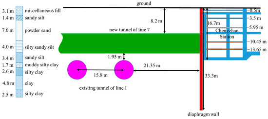
Figure 1.
Profile view of the project for the new tunnel of Line 7.
The spacing between the existing Line 1 and the new Line 7 near the station was approximately 15.8 m, with the new Line 7 at a horizontal distance of 16 m and a vertical distance of only 1.95 m. Line 7 was oblique to Line 1 at an angle of 80°, as shown in Figure 2. Both tunnels were constructed using the shield construction method. The segments were made of C50 material with an inner diameter of 5500 mm, an outer diameter of 6200 mm, and a segment thickness of 350 mm. The segments were joined with bent bolts, and each ring shield segment was divided into six pieces, installed by the erector of the shield machine.
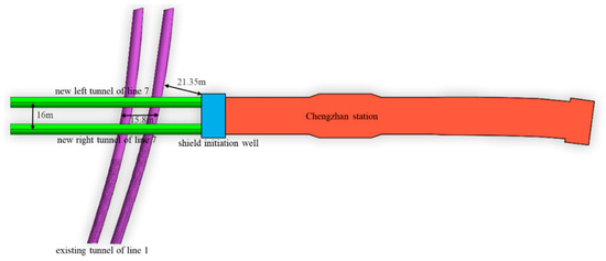
Figure 2.
Planned tunnel view of the project.
In this scenario, the existing tunnel experienced multiple construction disturbances. These primarily included the foundation pit excavation and structural construction at the shield initiation well of the Chengzhan station, along with the upper sections of the right-line shield for the new tunnel and the upper section of the left-line shield for the new tunnel.
2.2. Geology and Soil Parameters
The shield section of Line 7 primarily traverses soft soil layers, including powdered sand, silt with sandy silt, and sandy silt. The strata separating the new and existing tunnels consist of silt and sandy silt. The geotechnical investigation report for Hangzhou Metro Line 7 provided the fundamental and model parameters of soil mass, which were derived from a combination of indoor soil tests, in situ tests, and hydrogeological tests.
The first layer was miscellaneous fill, which was loose and dry~slightly wet. This layer consisted primarily of clay and gravel and had a thickness of approximately 3 m. The second layer consisted of powdered sand that was very wet and slightly dense~medium-dense, with a small amount of thin layer of viscous soil with a thickness of 8.4 m. This was followed by silty sand with sandy silt, a saturated, medium-dense state that was locally slightly dense. This soil composition contained mica debris and, occasionally, clay clumps with a thickness of approximately 4.0 m. The fourth layer consisted of sandy silt, which was wet, slightly dense, and 3.4-m thick, with low dry strength and toughness, and contained mica debris. The fifth layer was a silty clay layer with high dry strength and toughness, localized inclusions of silty soil, and a thickness of approximately 4.3 m. The sixth layer was a clay layer, primarily made of soft plastic and local fluid plastic, with high dry strength and medium toughness, containing organic matter with a thickness of approximately 4.8 m. Layer 7, with a thickness of 16.5 m, was puddingstone in a saturated and dense state, containing a gravel content of roughly 60% to 70% with good roundness and a clay content generally less than 5%. Layer 8 consisted of 3.1 m of strongly weathered rock, featuring an argillaceous structure and a thickly layered structure. The integrity of most organizational structures was compromised, with an incomplete core, developed cracks, soft rock, and local inclusions of weathered rock blocks. Layer 9 was the final layer, which was a 12.5 m moderately weathered rock. It had an argillaceous structure with relatively developed cracks, primarily composed of quartz, feldspar, and rock debris. The cementing material was the parent clay of the water cloud with minor iron content, resulting in soft rock.
The analysis of the natural soil weight revealed that the miscellaneous fill soil layer was 17.5 KN/m, while the soil weight of the other layers was greater than 19 KN/m. Notably, the strongly weathered rock layer and moderately weathered rock layer were particularly dense, each with a unit weight of 25 KN/m. Regarding soil cohesion, the upper four soil layers exhibited relatively low cohesion, all under 10 Kpa. In contrast, the layers below the transition from sandy soil resulted in a significant increase in cohesion, ranging from 25 to 28 Kpa. The boulder layer exhibited the lowest cohesion, while the weathered rock had the highest cohesion, with values ranging from 50 to 100 kPa. The inner friction angles of the second to fourth layers, as well as the seventh to ninth layers, were relatively high, ranging from 28° to 42°. In contrast, the internal friction angles of the remaining layers did not exceed 20°, a distinction primarily attributable to the differences between sandy soil and cohesive soil, as shown in Table 1.

Table 1.
Soil physical and mechanical parameters after simplification.
3. Midas GTS Simulation Process and Results
3.1. Geometric Model
In this study, MIDAS GTS NX finite element software was used to establish the analysis model. According to relevant specifications [43], the potential impact zone of foundation pit engineering is 2.0~3.0 H, where (H) represents the excavation depth of the foundation pit. Given that H = 16.7 m in this case, the boundaries of the model’s length and width must exceed 50.1 m from the edge of the foundation pit structure. The existing tunnel’s roof is buried at a depth of 16.35 m, which is less than 3D (D is the span of the tunnel; D = 6.2 m in this case). According to relevant specifications [44], generally, the affected zone of the tunnel is 1.0~2.0 h (h represents the buried depth of the tunnel bottom plate during external shield operations; h = 22.55 m in this case), beyond which it is unaffected by tunnel construction. Consequently, the numerical model’s boundary must extend beyond the study object’s outer edge for at least 45.1 m, the boundary range diagram of the model is illustrated in Figure 3.
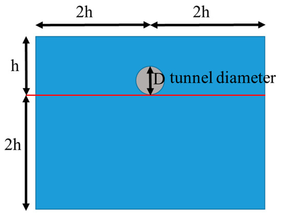
Figure 3.
Boundary range diagram of the model.
According to the literature [45,46], a numerical model can effectively eliminate the effect when the tunnel’s length surpasses 120 m. Furthermore, according to the relevant specifications [44], any distance exceeding 3.0D of the outer diameter of a tunnel of the urban rail transit structure constructed by the shield method falls within the unaffected zone. Consequently, the new tunnel’s length within the numerical model should extend at least 18.6 m beyond the intersection with the existing tunnel.
The subsurface conditions mainly determine the model’s lower boundary extension depth. A hard soil layer beneath can serve as the model’s lower boundary. Since soil stiffness increases with depth, a lower boundary situated well below the foundation pit’s bottom exerts a minimal impact on the calculated results [47]. Given that the level below 47.5 m in this instance is a moderately weathered rock layer, the height of the model was set to a depth well beyond the foundation pit, specifically at 60 m.
To mitigate the boundary effect on the numerical simulation results, the model’s length was established at 150 m for the new tunnel, extending approximately 80 rings beyond the existing tunnel point. The width was set to 78 m at the foundation pit’s outer edge, with approximately 70 rings from the new to the existing tunnel’s crossing point. The height of the model was determined to be twice the depth of the underground diaphragm wall, totaling 60 m, the finite element model is showed in Figure 4.
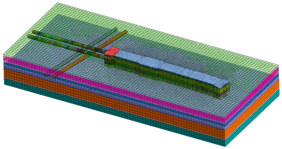
Figure 4.
Diagram illustrating the finite element model of an existing tunnel undergoing various disturbances.
3.2. Constitutive Model
In the construction model, the plate elements represent tunnel segments, underground diaphragm walls, and shield shells of the shield machine. In contrast, beam elements are used for the concrete support, crown beam, waist beam, and steel struts. The soil constitutive model employs the modified Mohr–Coulomb model, an improved constitutive model based on Mohr–Coulomb, which is suitable for various types of foundations, particularly materials with frictional properties such as sand. It simulates the combined behavior of nonlinear elastic and elastoplastic models, incorporating a power–rate relationship. The shear yield surface of the modified Mohr–Coulomb aligns with that of the traditional constitutive model. However, the compressive yield surface adopts an elliptical hat constitutive model. Unlike traditional fully elastic and semi-plastic stress models, the elastic yield point plane in the modified Mohr–Coulomb model is not static within the space of high principal stress but expands in response to the plastic strain of the material [48]. The modified Mohr–Coulomb model has replaced the hyperbolic model [49], reintroducing plastic stress theory and establishing an upper yield limit [50]. For this study, the reference compression modulus () at 100 kPa, based on the investigation report, was utilized. The reference secant stiffness () [51] and the reference unloading and reloading moduli () were derived from the literature [51,52].
In this study, we streamlined the soil layer by merging strata with similar properties, resulting in a simplified representation of all soil layers as horizontal layers. This approach prevents the creation of excessively small layering during grid division in the numerical simulation, thereby enhancing mesh quality and ensuring better convergence of the calculations. The soil material attributes is detailed in the following Table 2. Table 3 displays the structural material attributes.
Table 2.
Soil material attributes.
Table 3.
Structural material attributes.
3.3. Load and Constraint
3.3.1. Construction Load
The foundation of the current tunnel experiences deformation and displacement solely during the excavation of the foundation pit and the installation of support, excluding any consideration of ground overload.
The hydraulic thrust of the shield tunneling machine ranges from 800 to 1200 T, representing the total power provided by the hydraulic cylinder to the shield machine. For our analysis, we adopted a median value of 1000 T as the thrust F of the shield tunneling machine. This thrust F encompasses the pressure that F1 exerted on the palm surface through the cutter head of the shield machine, the friction resistance F2 of the jack to overcome the shield shell and surrounding strata, the friction resistance F3 between the segment and the shield tail, and the traction resistance F4 of the truck and supporting equipment [53].
The positive propulsive resistance F1 acting on the central axis of the soil palm surface was defined as equal to half of the horizontal water and soil pressure. Moreover, 50% of the water and soil pressure between the top and bottom of the shield machine was chosen as F1, and an additional 15 kPa was added on this basis. In this study, F1 = 128 kPa [54,55].
The thrust’s remaining part was simplified to the resistance of the soil acting on the shield line element.
Therefore, the shield force in this paper is = 218 kPa
In the tunneling process, synchronous grouting is always used to fill the shield tail gap, and the grouting pressure acts on the segment [56,57]. This synchronous grouting pressure usually does not exceed more than 0.3 MPa, and a grouting pressure of 250 kPa was selected in this study, as showed in Table 4.
Table 4.
Construction load table.
3.3.2. Boundary Constraint
The standard constraint form was employed, where the surrounding boundary is limited only to its horizontal displacement, the top is a free boundary, and the bottom is a fixed constraint. That is, the boundary conditions of the model limited the X-direction displacement of nodes on both sides of the model in the Y-direction, the Y-direction displacement of nodes on both sides of the X-direction, and the X, Y, and Z displacements of nodes on the bottom of the model.
3.3.3. Interface Unit
In a pit engineering foundation, the underground diaphragm wall interacts with the soil. The interaction between the enclosure structure and soil significantly affects the soil settlement outside the pit, the impact range of the settlement, and the influence of the excavation on existing tunnels. The finite element method, rooted in continuum mechanics theory, serves as an analytical tool to study these effects. This method cannot effectively assess the force and deformability of the relative displacement between materials. To enhance the accuracy of our finite element analysis and align it more closely with the actual foundation pit finite element analysis, a contact surface element was incorporated into the contact surface between the underground diaphragm wall and soil mass.
3.3.4. Self-Weighted Load
A self-weight load was applied to the entire model to simulate the gravity action of all the structures.
3.4. Construction Process Simulation
Numerical simulation software cannot accurately simulate the construction process. The stiffness transfer method was utilized to simulate both the excavation and support erection processes of the foundation pit and shield tunneling process effectively. Progressive steps promote the construction process, and the excavation of the foundation pit or shield tunneling is the migration process of stiffness and load [58].
In stage 1, the initial stress stage, all the soil layers were activated, and the displacement was cleared to zero. In stage 2, the existing tunnel construction stage, the soil of the existing tunnel portion was frozen, and the existing tunnel element was activated. In stage 3, the foundation pit excavation construction stage, we constructed a foundation pit envelope and activated the interface unit and rigid connection; thereafter, we activated the shield’s initial well support and passivated the soil above the excavation face. Lastly, we activated the standard section support successively and passivated the soil above the excavation face. In stage 2, the new tunnel construction stage, we passivated the soil of the new tunnel excavation surface in turn, activated the segments, and activated the excavation pressure and hydraulic jack pressure; thereafter, we passivated the driving pressure and hydraulic jack pressure of the last segment successively and activated the grouting layer and grouting pressure. Through the above steps, the numerical simulation of the construction phase was realized in the finite element software. The detailed steps are shown in Figure 5.
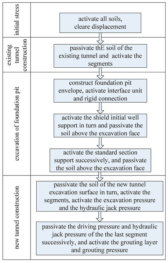
Figure 5.
Construction process of the finite element software simulation.
3.5. Numerical Simulation Insights
3.5.1. Vertical Displacement
As shown in Figure 6, (1) the excavation of the foundation pit had little influence on the vertical displacement of the existing operating tunnel. The arch of the existing up-line tunnel shows a settlement trend near the side of the foundation pit, with a maximum settlement of −0.04 mm, which corresponds to the middle of the parallel plane between the foundation pit and the existing tunnel line. The arch waist of the tunnel shifts from the side of the foundation pit, where the maximum uplift value is 0.06 mm. The position corresponds to the corner of the parallel plane between the foundation pit and the existing tunnel line, particularly since the segment has a slight tendency to twist toward the direction of the foundation pit. (2) The over-crossing tunnels cause the progressive trend of the existing tunnel: After the shield tunneling of the new right-line tunnel, the existing tunnel corresponds to the arch crossing point of the new tunnel, and the existing tunnel is the largest, measured at 1.49 mm. (3) Following the shield tunneling of the new left-line tunnel, the floating of the existing tunnel increases continuously, and the maximum floating value is 2.44 mm, which corresponds to the middle part of the intersection of the right and left lines of the new tunnel and the existing tunnel plane. (4) The impact degree of the up-line near the foundation pit of the existing tunnel is greater than the down-line away from the foundation pit, and the maximum vertical displacement occurs in the up-line of the existing tunnel.
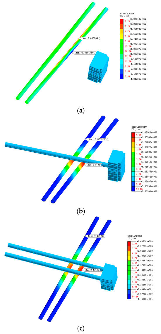
Figure 6.
Vertical displacement cloud image of an existing tunnel subjected to several disturbances. (a) Vertical displacement cloud image of an existing tunnel subjected to the foundation pit (b) Vertical displacement cloud image of an existing tunnel subjected to the new right-line tunnel (c) Vertical displacement cloud image of an existing tunnel subjected to the new left-line tunnel.
3.5.2. Horizontal Displacement
In Figure 7, (1) the excavation of the foundation pit has minimal influence on the horizontal displacement of the existing tunnel, the existing tunnel comes with horizontal displacement toward the foundation pit, and the horizontal displacement of the tunnel arch’s bottom on the up-line is the largest, measured at 0.67 mm, which corresponds to the middle of the parallel plane between the foundation pit and the existing tunnel line. (2) The new tunnel’s over-crossing induces horizontal displacement in the existing tunnel, moving it away from the foundation pit. After the shield tunneling of the right-line tunnel, the maximum horizontal displacement of the existing tunnel occurs at the intersection point with the new tunnel, measured at −2.31 mm. (3) After the shield tunneling of the new left-line tunnel, the existing tunnel exhibits a horizontal displacement trend away from the foundation pit. The maximum displacement was measured at −3.58 mm, which corresponds to the middle part of the intersection of the right and left lines of the new tunnel and the existing tunnel plane. (4) The impact degree of the up-line near the foundation pit of the existing tunnel is greater than that of the down-line away from the foundation pit, and the maximum value of the horizontal displacement occurs in the up-line of the existing tunnel.
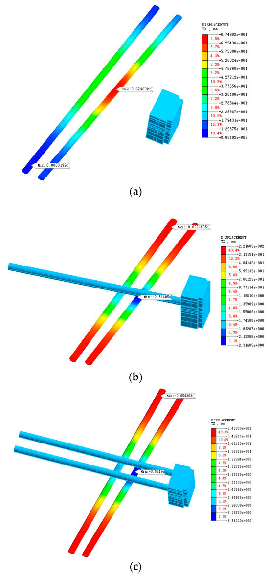
Figure 7.
Horizontal displacement cloud image of an existing tunnel subjected to several disturbances. (a) Horizontal displacement cloud image of an existing tunnel subjected to the foundation pit (b) Horizontal displacement cloud image of an existing tunnel subjected to the new right-line tunnel (c) Horizontal displacement cloud image of an existing tunnel subjected to the new left-line tunnel.
4. Analysis of the Field Measurement Data
4.1. Automatic Monitoring Arrangement and Monitoring Content
The TM50 total station produced by Leica (Heerbrugg, Switzerland) was utilized to monitor the deformation of the existing Line 1 tunnel automatically and manually check it regularly in this project. The monitoring focused on the excavation of the foundation pit and the new Line 7 shield crossing the existing line. Two stations were arranged in the upper and lower sections of the track operation area of Line 1, forming two automatic monitoring networks. The monitoring length of each section was approximately 200 m. A monitoring section was arranged every five rings in Section Line 1 for the foundation pit construction stage of the station, which corresponded to the projection range of the foundation pit, and a monitoring section was arranged every ten rings outside the projection range. In the construction phase of the shield tunneling machine of Line 7 across Line 1, a monitoring section will be arranged every 2 to 3 ring intervals in the projection range and 15 m outside the projection range of the shield tunnel; a monitoring section will be arranged every five ring intervals in the 15 m~55 m outside the projection range. The monitoring range of the up-line and down-line was set to 31 sections. Among them, 15 sections were used in the foundation pit construction stage, in which 16 sections were encrypted in the middle when the shield was crossed. The arrangement of monitoring points is depicted in Figure 8. Two sets of monitoring prisms were positioned on either side of each monitoring section to track both the vertical and horizontal displacement of the track ballast. Refer to Figure 9 for the detailed layout of the monitoring prisms.
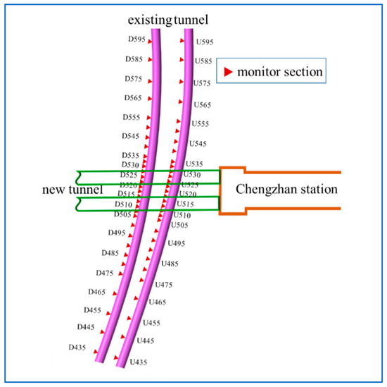
Figure 8.
Sectional view of the existing tunnel monitoring points.
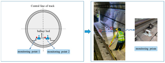
Figure 9.
Layout of the automated monitoring points on the segment.
4.2. Actual Construction Process
The effect of the new construction on the existing tunnel is primarily the foundation pit excavation, structural construction of the shield initiation well, and the new tunnel over-crossing the existing tunnel. The tunnel over-crossing the existing line is divided into right-line over-crossing and left-line over-crossing. The specific construction process is detailed in Table 5.
Table 5.
Construction process and schedule node for each stage.
4.3. Analysis of the Monitoring Data
4.3.1. Vertical Displacement
The researcher organized the vertical displacement values of the existing tunnel monitoring points at each construction stage. The monitoring of each point is impacted by factors like the accuracy of measuring instruments, the vibration of operating subway trains, and the error of manual retesting. Furthermore, some points are discrete, and adjacent monitoring points revealed the phenomenon of up-and-down vibration and jumping. For the regression of the monitoring points of each section, the researcher utilized polynomials to fit the data:
where is the intercept coefficient and is the slope coefficient. The fitted curve is presented in Figure 10.
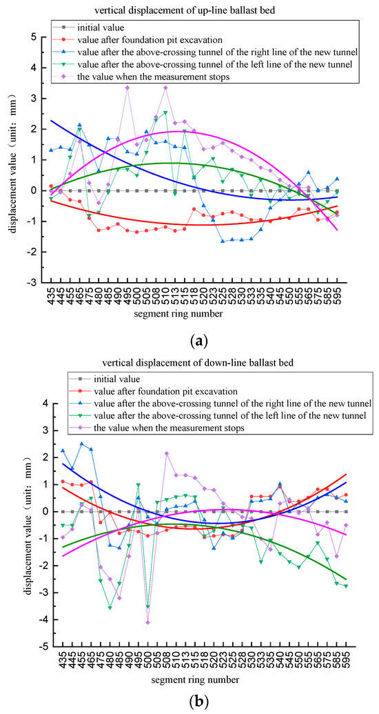
Figure 10.
Vertical displacement of existing tunnels subjected to multiple disturbances. (a) Vertical displacement of up-line ballast bed subjected to multiple disturbances (b) Vertical displacement of down-line ballast bed subjected to multiple disturbances.
In Figure 10, during the excavation stage of the foundation pit of the shield initial well, the up-line of the existing tunnel exhibits a settlement trend, with a large settlement in the middle and a small settlement at both ends, and a maximum settlement value of −1.35 mm. This measurement result is consistent with those of Zheng et al. [59] and Meng et al. [60], which indicated the same conclusion. After the new right-line shield tunneling, the existing tunnel as a whole uplifts and the middle of the up-line of the existing tunnel returns to its initial position after floating. One end of the tunnel floats, while the other end settles slightly. After the above-crossing tunneling of the left-line shield, the existing tunnel exhibits a trend of partial upward floating and partial settlement. Generally, floating occurs in the middle of the up-line of the existing tunnel, and the two ends return to their initial positions. When the final data converged to meet the requirements of the stop test, the middle of the existing tunnel up-line uplifted, the maximum floating value was 3.35 mm, and the two ends returned to the initial position. This observed outcome aligns with the findings reported by Chen et al. [61].
Vertical settlement occurred in the middle part of the down-line of the existing tunnel, and a slight uplift occurred at both ends during the excavation stage of the shield initial well. After the new right-line shield tunneling, the overall vertical displacement trend of the down-line remained consistent with the foundation pit excavation stage and did not change. After the above-crossing tunneling of the left-line shield, the middle part of the down-line was still in a slight settlement. However, the two ends changed significantly, from the original uplift to settlement. Considering that all the values were within the range , the change was still not significant. For the final phase of the stop test, the middle part of the down-line of the existing tunnel eventually returned to the initial state; yet, the two ends of the tunnel remained in the settlement state. Generally, the vertical displacement law of the down-line is most likely to be the up-line, and the polynomial curve has the same shape. Still, the interval range of its displacement value is more moderate than the up-line, and it always changes around the initial value.
4.3.2. Horizontal Displacement
Similarly, the researchers utilized polynomials to present the curve fitting of the monitoring data, and the fitting results are shown in Figure 11. Figure 11 indicates the excavation of the pit at the shield initial well, which causes horizontal displacement toward the excavation direction of the existing tunnel. The displacement value of the middle part of the existing tunnel was the largest, measured at 1.85 mm. The displacement value of both ends gradually decreased and approached the initial value at the end, similar to the vertical displacement. This measured result is consistent with the research conclusions of Zheng et al. [59] and Meng et al. [60]. After the new right-line shield tunneling, the existing tunnel generated a severe horizontal displacement away from the foundation pit. The displacement value of the middle part of the existing tunnel was the largest, measured at −3.80 mm, and the displacement value of the two ends gradually decreased.
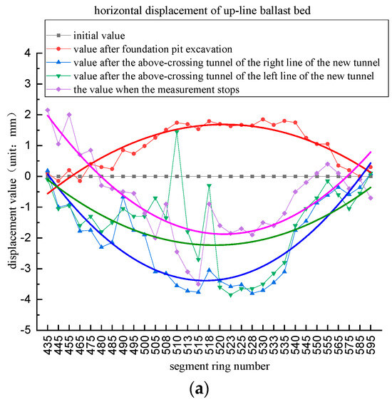
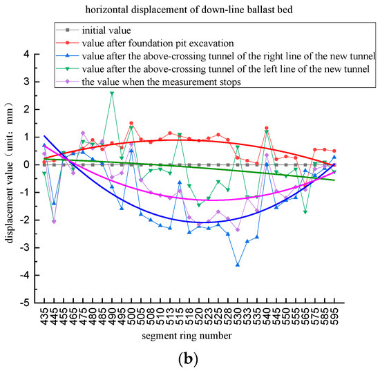
Figure 11.
Horizontal displacement of tunnels subjected to multiple disturbances. (a) Horizontal displacement of up-line ballast bed subjected to multiple disturbances (b) Horizontal displacement of down-line ballast bed subjected to multiple disturbances.
The relief of horizontal displacement in the existing tunnel toward the foundation pit occurred following the over-crossing tunneling by the left-line shield. The overall tunnel’s horizontal position value was minimized to varying extents. When the final data were connected to meet the requirements of the stop test, the existing tunnel was displaced a little further toward the foundation pit. Moreover, horizontal displacement away from the foundation pit occurred in the middle part of the tunnel, and horizontal displacement toward the foundation pit occurred slightly at both ends.
During the entire construction stage, the horizontal displacement of the down-line of the existing tunnel was the same as that of the up-line; however, its displacement value was reduced compared to that of the up-line. The only difference is that after the left-line shield tunneling of the new tunnel, the horizontal displacement of the downward line of the existing tunnel in the direction of the foundation pit sprang back sharply and approached the initial position. However, the final state was still highly consistent with the up-line.
5. Comparison of Numerical Simulation Results to Measured Data
In Figure 5, Figure 6, Figure 10 and Figure 11, the results shown by the finite element software and the conclusions gathered from the analysis of the actual automatic monitoring data exhibit that the vertical and horizontal displacement laws of the existing tunnel structure are the same after multiple disturbances caused by the excavation of the foundation pit and the above-crossing of the newly built shield tunnel. Three representative sections were chosen: S513 and S528, intersecting the up-lines of Lines 7 and 1, and S520, corresponding to the middle of the foundation pit excavation face. By examining data from monitoring and numerical simulations at various construction stages, an in-depth analysis of the deformation patterns of the existing tunnel was conducted.
Figure 12 shows that the measured values of the three typical sections of the existing tunnel exhibit settlement and uplift. After multiple disturbances, the measured values were in an upward state, and the values of changes in each construction stage were small and within the range . The numerical simulation results show that the excavation of the foundation pit has no obvious impact on the existing tunnel. However, after the new shield tunneling, the three typical sections of the existing tunnel were continuously uplifted. Furthermore, the floating value continued to increase. The final value was 4.7 times the measured value in the range .
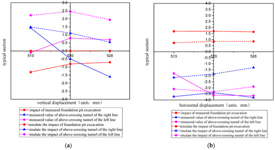
Figure 12.
Comparison of the numerical simulation results and measured data of a typical section. (a) Comparison of vertical displacement between numerical simulation results and measured data of typical section (b) Comparison of horizontal displacement between numerical simulation results and measured data of typical section.
Specific requirements were stipulated for the safety control index value of urban rail transit structures according to [43]. In this case, the warning value for the horizontal displacement and vertical displacement of existing tunnels was 10 mm, and the control value was 20 mm. According to the provisions of [44], the horizontal displacement control value of the existing tunnel in this case was 8 mm, and the vertical displacement was 10 mm. In summary, the control standard in this case was the acceptable limit of a horizontal displacement of 8 mm and vertical displacement of 10 mm.
Automated monitoring was performed using the Leica GeoMoS software (GeoMoS-CH), which consists of two main parts: a monitor and an analyzer. The monitor has a well-developed measurement and calculation program that provides an ideal solution for applications requiring extremely high accuracy. According to the characteristics and relevant requirements of the project, automatic monitoring systems were established in the track running areas of the up-line and down-line, with monitoring lengths of approximately 200 m. Considering the accuracy of the automatic measurements of the total station, the monitoring alarm value, and the site conditions, two stations each were established in the up-line and down-line tunnels, totaling four stations, and two automatic monitoring networks were constructed. During the construction process, the survey team conducted 24 joint measurements of the data points and manually reviewed the automatic monitoring data 84 times. The results showed that the maximum difference between the automatic and manual monitoring results of the up-line and down-line was ±2.1 mm, which is small and meets the requirements.
The obtained results indicate that the foundation pit excavation induces the movement of the existing tunnel toward the foundation pit. Simultaneously, the new tunnel results in a horizontal displacement of three representative sections away from the foundation pit direction. Notably, the left-line of the new tunnel shield tunneling across the existing line has a slight effect on the horizontal displacement of the existing tunnel. The outcomes from the numerical simulation illustrate that the foundation pit excavation leads to the existing tunnel shifting toward the foundation pit. Additionally, the excavation of the new tunnel results in the horizontal displacement of the existing tunnel away from the foundation pit. The numerical simulation findings align accurately with the measured results. However, the slight difference is that the existing tunnel is subjected to multiple disturbances caused by the shield tunneling of the new tunnel, in which the displacement away from the foundation pit continues to increase. The final horizontal displacement was in line with the measured value, which was 1.03 times the final state of the measured value.
6. Conclusions
The excavation of the foundation pit and construction of the over-crossing shield when the existing tunnel was disturbed by excavation of the foundation pit and construction of the above-crossing shield excavation was successful owing to the foundation pit, which caused slight settlement of the existing tunnel, and the over-crossing shield caused vertical uplift of the existing tunnel. The vertical displacement caused by the above-crossing shield was far greater than the influence of foundation pit excavation. The maximum vertical displacement occurred in the middle of the crossing point between the two lines of the above-crossing tunnel and the existing tunnel. Numerical simulation software and the analysis of the measured data have led to the abovementioned conclusions.
The foundation pit excavation induced horizontal displacement of the existing tunnel segments toward the foundation pit. Subsequently, the over-crossing shield provoked horizontal displacement of the existing tunnel in the tunneling direction. The impact of shield tunneling on the horizontal displacement of the existing tunnel far exceeded that caused by foundation pit excavation. Numerical simulation software and the analysis of the measured data can prove the above conclusions.
In comparison to the measured values of three typical sections with the numerical simulation data, it was revealed that in the final state, the numerical simulation results for the vertical displacement are much larger than the measured values, which was 4.7 times the measured data. The numerical simulation results for the horizontal displacement agree with the measured data. Furthermore, when using numerical simulation software for evaluation, attention should be paid to minimizing the value of vertical displacement, or other numerical simulation methods should be used for comparison and confirmation.
The existing tunnel is subjected to multiple disturbances caused by foundation pit excavation and the above-crossing shield. Vertical displacement and horizontal displacement for the construction disturbances of the two parts have opposite influences. Certainly, multiple disturbances can offset each other’s partial displacement, thereby minimizing the final displacement.
The segment structure of the existing tunnel is gathered as a whole, wherein the stiffness reduction is caused by the bolted connection between the segments, which was not considered in this study. The numerical simulation did not consider the impact of groundwater because there was sandy soil in the soil layer, and the soil bulk density and effective stress were bound to be affected by the action of groundwater. This may have affected the accuracy of the numerical simulation to some extent.
Author Contributions
Conceptualization, F.Y. and X.H. (Xingbo Han); methodology, H.L.; software, H.L.; validation, X.H. (Xingbo Han) and X.H. (Xin Han); formal analysis, H.L.; investigation, X.H. (Xin Han); resources, H.L.; data curation, X.H. (Xingbo Han); writing—original draft preparation, H.L.; writing—review and editing, F.Y.; visualization, X.H. (Xin Han); supervision, F.Y.; project administration, H.L.; funding acquisition, X.H. (Xingbo Han). All authors have read and agreed to the published version of the manuscript.
Funding
This work was financially supported by the National Science Foundation of China (Nos. 51678062 and 51878060).
Institutional Review Board Statement
Not applicable.
Informed Consent Statement
Not applicable.
Data Availability Statement
The original contributions presented in the study are included in the article, further inquiries can be directed to the corresponding author.
Conflicts of Interest
The authors declare no conflict of interest.
References
- Sharafat, A.; Latif, K.; Seo, J. Risk analysis of TBM tunneling projects based on generic bow-tie risk analysis approach in difficult ground conditions. Tunn. Undergr. Space Technol. 2021, 111, 103860. [Google Scholar] [CrossRef]
- Zhang, K.; Zhao, X.; Zhang, Z. Influences of tunnelling parameters in tunnel boring machine on stress and displacement characteristics of surrounding rocks. Tunn. Undergr. Space Technol. 2023, 137, 105129. [Google Scholar] [CrossRef]
- Zhou, H.; Zhao, Y.; Shen, Q.; Yang, L.; Cai, H. Risk assessment and management via multi-source information fusion for undersea tunnel construction. Autom. Constr. 2020, 111, 103050. [Google Scholar] [CrossRef]
- Wang, F.-W.; Feng, A.-J. Statistics and development analysis of urban rail transit in China in 2022. Tunn. Constr. 2023, 43, 521–528. [Google Scholar]
- Zhou, S.-H. Underground Shield Tunneling Project; Science Press: Beijing, China, 2017; ISBN 9787030546975. [Google Scholar]
- Wang, L.-X.; Liang, R.-Z.; Li, Z.-C.; Kang, C.; Xiao, M.-Z.; Wu, W.-B.; Gao, K.; Guo, Y. Heave deformation of existing shield tunnel induced by over-crossing excavation. Eng. Mech. 2022, 39, 130–140. [Google Scholar]
- Liu, B.; Yua, Z.-W.; Han, Y.-H.; Wang, Z.-L.; Zhang, R.-H.; Wang, S.-J. Analytical solution for the response of an existing tunnel induced by abovecrossing shield tunneling. Comput. Geotech. 2020, 124, 1–15. [Google Scholar] [CrossRef]
- Bousbia, N.; Messast, S. Numerical modeling of two parallel tunnels interaction using three-dimensional Finite Elements Method. Geomech. Eng. 2015, 9, 775–791. [Google Scholar]
- Hu, M.-Y. The Effect of Excavation Unloading on the Deformation of Existing Underlying Shield Tunnel. In Proceedings of the 4th International Conference on Transportation Geotechnics, Chicago, IL, USA, 23–26 May 2021. [Google Scholar]
- Chen, R.-P.; Meng, F.-Y.; Li, Z.-C.; Ye, Y.-H.; Ye, J.-N. Investigation of response of metro tunnels due to adjacent large excavation and protective measures in soft soils. Tunn. Undergr. Space Technol. 2016, 58, 224–235. [Google Scholar] [CrossRef]
- Chang, C.-T.; Sun, C.-W.; Duann, S.; Hwang, R.N. Response of a Taipei Rapid Transit System (TRTS) tunnel to adjacent excavation. Tunn. Undergr. Space Technol. 2001, 16, 151–158. [Google Scholar] [CrossRef]
- Chang, C.-T.; Wang, M.-J.; Chang, C.-T.; Sun, C.-W. Repair of displaced shield tunnel of the Taipei rapid transit system. Tunn. Undergr. Space Technol. 2001, 16, 167–173. [Google Scholar] [CrossRef]
- Xin, W.; Pang, C.-R. Influence of foundation pit excavation on existing shield tunnel and its protection range. Appl. Mech. Mater. 2014, 580–583, 1258–1263. [Google Scholar]
- Yong, T.; Ye, L.; Wang, D. Practical Solutions for Concurrent Excavation of Neighboring Mega Basements Closely Surrounded by Utility Tunnels in Shanghai Hongqiao CBD. Pract. Period. Struct. Des. Constr. 2019, 24, 05019005. [Google Scholar]
- Meng, F.-Y.; Chen, R.-P.; Wu, H.-N.; Xie, S.-W.; Liu, Y. Observed Behaviors of a Long and Deep Excavation and Collinear Underlying Tunnels in Shenzhen Granite Residual Soil. Tunn. Undergr. Space Technol. 2020, 103, 103504. [Google Scholar] [CrossRef]
- Zheng, G.; Yang, X.; Zhou, H.; Du, Y.; Sun, J.; Yu, X. A simplified prediction method for evaluating tunnel displacement induced by laterally adjacent excavations. Comput. Geotech. 2018, 95, 119–128. [Google Scholar] [CrossRef]
- Ng, C.; Sun, H.; Lei, G.; Shi, J.; Mašín, D. Ability of three different soil constitutive models to predict a tunnel’s response to basement excavation. Can. Geotech. J. 2015, 52, 1685–1698. [Google Scholar] [CrossRef]
- Zheng, G.; Wei, S.-W. Numerical analyses of influence of overlying pit excavation on existing tunnels. J. Cent. South Univ. Technol. 2008, 15, 069–075. [Google Scholar] [CrossRef]
- Li, M.-G.; Chen, J.-J.; Wang, J.-H.; Zhu, Y.-F. Comparative study of construction methods for deep excavations above shield tunnels. Tunn. Undergr. Space Technol. 2018, 71, 329–339. [Google Scholar] [CrossRef]
- Ng, C.W.W.; Shi, J.; Mašín, D.; Sun, H.; Lei, G.H. Influence of sand density and retaining wall stiffness on three-dimensional responses of tunnel to basement excavation. Can. Geotech. J. 2015, 52, 1811–1829. [Google Scholar] [CrossRef]
- Meng, F.; Chen, R.; Liu, S.; Wu, H. Centrifuge Modeling of Ground and Tunnel Responses to Nearby Excavation in Soft Clay. J. Geotech. Geoenviron. Eng. 2021, 147, 04020178. [Google Scholar] [CrossRef]
- Meng, F.; Chen, R.; Xu, Y.; Wu, H.; Li, Z. Centrifuge Modeling of Effectiveness of Protective Measures on Existing Tunnel Subjected to Nearby Excavation. Tunn. Undergr. Space Technol. 2021, 112, 103880. [Google Scholar] [CrossRef]
- Zhang, J.-F.; Chen, J.-J.; Wang, J.-H.; Zhu, Y.-F. Prediction of tunnel displacement induced by adjacent excavation in soft soil. Tunn. Undergr. Space Technol. 2013, 36, 24–33. [Google Scholar] [CrossRef]
- Liang, R.; Wu, W.; Yu, F.; Jiang, G.; Liu, J. Simplified method for evaluating shield tunnel deformation due to adjacent excavation. Tunn. Undergr. Space Technol. 2018, 71, 94–105. [Google Scholar] [CrossRef]
- Wei, G. Measurement and analysis of impact of foundation pit excavation on below existed shield tunnels. Rock Soil Mech. 2013, 34, 1421–1428. [Google Scholar]
- Yong, T.; Li, X.; Kang, Z.; Liu, J.; Zhu, Y. Zoned Excavation of an Oversized Pit Close to an Existing Metro Line in Stiff Clay: Case Study. J. Perform. Constr. Facil. 2015, 29, 04014158. [Google Scholar]
- Huang, X.; Huang, H.-W.; Zhang, D.-M. Centrifuge modelling of deep excavation over existing tunnels. Geotech. Eng. 2014, 167, 3–18. [Google Scholar] [CrossRef]
- Kim, S.H. Model testing of closely spaced tunnels in clay. Geotechnique 1998, 48, 375–388. [Google Scholar] [CrossRef]
- Byun, G.W.; Kim, D.G.; Lee, S.D. Behaviour of the Ground in Rectangularly Crossed Area Due to Tunnel Excavation under the Existing Tunnel. Tunn. Undergr. Space Technol. 2006, 21, 361. [Google Scholar] [CrossRef]
- Hansmire, W.; Parker, H.; Ghaboussi, J. Effects of shield tunneling over subways. In Proceedings of the 5th Rapid Excavation and Tunneling Conference, San Francisco, CA, USA, 3–7 May 1981; Volume 1, pp. 254–276. [Google Scholar]
- Ghaboussi, J.; Hansmire, W.H.; Parker, H.W.; Kim, K.J. Finite element simulation of tunneling over subways. J. Geotech. Eng. 1983, 109, 318–334. [Google Scholar] [CrossRef]
- Deng, J.-Y.; Yao, A.-J.; Zhou, J.; Chu, P.-Z. Analysis on Field Measurement of Shield Construction of Adjacent Tunnels. Chin. J. Undergr. Space Eng. 2020, 16, 1809–1817. [Google Scholar]
- Liang, R.-Z. Simplified analytical method for evaluating the effects of overcrossing tunnelling on existing shield tunnels using the nonlinear Pasternak foundation model. Soils Found. 2019, 59, 1711–1727. [Google Scholar] [CrossRef]
- Winkler, E. Die Lehre von der Elastizität und Festigkeit. In The Theory of Elasticity and Stiffness; H. Dominicus: Prague, Czechoslovakia, 1867. (In German) [Google Scholar]
- Pasternak, P.L. On a New Method of Analysis of An Elastic Foundation by Means of Two Foundation Constants; Gosudarstvennoe Izdatelstvo Literaturi po Stroitelstvu i Arkhitekture: Moscow, Russia, 1954. (In Russian) [Google Scholar]
- Terzaghi, K. Evaluation of coefficient of subgrade reaction. Géotechnique 1955, 5, 297–326. [Google Scholar] [CrossRef]
- Vesić, A.B. Bending of beams resting on isotropic elastic solid. J. Eng. Mech. Div. 1961, 87, 35–53. [Google Scholar] [CrossRef]
- Liang, R.; Xia, T.; Hong, Y.; Yu, F. Effects of above-crossing tunnelling on the existing shield tunnels. Tunn. Undergr. Space Technol. 2016, 58, 159–176. [Google Scholar] [CrossRef]
- Do, N.-A.; Dias, D.; Oreste, P.; Djeran-Maigre, I. Three-dimensional numerical simulation of a mechanized twin tunnels in soft ground. Tunn. Undergr. Space Technol. 2014, 42, 40–51. [Google Scholar] [CrossRef]
- Zhang, D.; Liu, B.; Qin, Y. Construction of a large-section long pedestrian underpass using pipe jacking in muddy silty clay: A case study. Tunn. Undergr. Space Technol. 2016, 60, 151–164. [Google Scholar] [CrossRef]
- Huang, X.; Schweiger, H.F.; Huang, H. Influence of Deep Excavations on Nearby Existing Tunnels. Int. J. Géoméch. 2013, 13, 170–180. [Google Scholar] [CrossRef]
- Shi, J.; Fu, Z.; Guo, W. Investigation of geometric effects on three-dimensional tunnel deformation mechanisms due to basement excavation. Comput. Geotech. 2019, 106, 108–116. [Google Scholar] [CrossRef]
- GB 50911-2013; Code for Monitoring Measurement of Urban Rail Transit Engineering. Ministry of Housing and Urban-Rural Development of the People’s Republic of China: Beijing, China, 2013.
- CJJ/T202-2013; Technical Code for Protection Structures of Urban Rail Transit. Ministry of Housing and Urban-Rural Development of the People’s Republic of China: Beijing, China, 2013.
- Kasper, T.; Meschke, G. A 3D finite element simulation model for TBM tunnelling in soft ground. Int. J. Numer. Anal. Methods Géoméch. 2004, 28, 1441–1460. [Google Scholar] [CrossRef]
- Huynh, T.; Chen, J.; Sugimoto, M. Analysis on shield operational parameters to steer articulated shield. Jpn. Geotech. Soc. Spéc. Publ. 2016, 2, 1497–1500. [Google Scholar] [CrossRef]
- DGTJ08-61-2018; Technical Code for Excavation Engineering. Shanghai Housing and Urban and Rural Construction Management Commission: Shanghai, China, 2018.
- MIDAS GTS NX Advanced Textbook. Available online: https://midas.yunzhan365.com/books/cwxb/mobile/index.html (accessed on 10 March 2021).
- Duncan, J.; Chang, C. Nonlinear Analysis of Stress and Strain in Soils. J. Soil Mech. Found. Div. 1970, 96, 1629–1653. [Google Scholar] [CrossRef]
- Sun, L.-C. Numerical Analysis and Deformation Prediction of Deep Foundation Pit Based on Modified Moorcoulomb Model. Master’s Thesis, Hebei University of Architecture, Zhangjiakou, China, 2021. [Google Scholar]
- Liu, G.-B.; Wang, W.-D. Foundation Pit Engineering Manual; China Architecture & Building Press: Beijing, China, 2009; ISBN 9787112115525. [Google Scholar]
- Zhang, Y.; Xue, Y.-Q.; Wu, J.-C.; Pu, X.-F.; Liu, Y.-T.; Wei, Z.-X.; Li, Q.-F. Parameter study of Duncan-Zhang model of Quaternary soil layer in Shanghai. Hydrogeol. Eng. Geol. 2008, 219, 19–22. [Google Scholar]
- Zhang, Z.-H. Shield and Shield Construction Technology; China Architecture & Building Press: Beijing, China, 2019; ISBN 9787112237913. [Google Scholar]
- Zhu, J.-F.; Xu, R.-Q.; Liu, G.-B. Analytical prediction for tunnelling-induced ground movements in sands considering disturbance. Tunn Undergr Space Technol 2014, 41, 165–175. [Google Scholar] [CrossRef]
- Kavvadas, M.; Litsas, D.; Vazaios, I.; Fortsakis, P. Development of a 3D finite element model for shield EPB tunnelling. Tunn. Undergr. Space Technol. 2017, 65, 22–34. [Google Scholar] [CrossRef]
- Ninić, J.; Meschke, G. Simulation based evaluation of time-variant loadings acting on tunnel linings during mechanized tunnel construction. Eng. Struct. 2017, 135, 21–40. [Google Scholar] [CrossRef]
- Do, N.-A.; Dias, D.; Oreste, P.; Djeran-Maigre, I. Three-dimensional numerical simulation for mechanized tunnelling in soft ground: The influence of the joint pattern. Acta Geotech. 2013, 9, 673–694. [Google Scholar] [CrossRef]
- Wang, M.-Q.; Chen, S.-H. 3-dimensional nonlinear finite element simulation of tunnel structure for moving-forward shield. Chin. J. Rock Mech. Eng. 2002, 21, 228–232. [Google Scholar] [CrossRef]
- Zheng, G.; Du, Y.-M.; Diao, Y.; Deng, X.; Zhu, G.-P.; Zhang, L.-M. Influenced zones for deformation of existing tunnels adjacent to excavations. Chin. J. Geotech. Eng. 2016, 38, 599–612. [Google Scholar]
- Meng, F.Y.; Chen, R.P.; Xu, Y.; Wu, K.; Wu, H.N.; Liu, Y. Contributions to responses of existing tunnel subjected to nearby excavation: A review. Tunn. Undergr. Space Technol. 2022, 119, 104195. [Google Scholar] [CrossRef]
- Chen, L.; Huang, H.; Wang, R. Analysis of the observed longitudinal settlement of a tunnel caused by an adjacent shield tunnelling on top. Chin. J. Civ. Eng. 2006, 39, 83–87. [Google Scholar]


Disclaimer/Publisher’s Note: The statements, opinions and data contained in all publications are solely those of the individual author(s) and contributor(s) and not of MDPI and/or the editor(s). MDPI and/or the editor(s) disclaim responsibility for any injury to people or property resulting from any ideas, methods, instructions or products referred to in the content. |
© 2024 by the authors. Licensee MDPI, Basel, Switzerland. This article is an open access article distributed under the terms and conditions of the Creative Commons Attribution (CC BY) license (https://creativecommons.org/licenses/by/4.0/).