Article

FAPR: An Adaptive Approach to Link Failure Recovery in SDN with High Speed and Low Interruption Rate

School of Electronic and Electrical Engineering, Shanghai University of Engineering Science, Shanghai 201620, China
*
Author to whom correspondence should be addressed.
Appl. Sci. 2024, 14(11), 4719; https://doi.org/10.3390/app14114719
Submission received: 8 May 2024 / Revised: 26 May 2024 / Accepted: 28 May 2024 / Published: 30 May 2024
(This article belongs to the Topic Next Generation Intelligent Communications and Networks)

Abstract

:
Link failures are the most common type of fault in software-defined networking (SDN), which is an extremely crucial aspect of SDN fault tolerance. Existing strategies include proactive and reactive approaches. Proactive schemes pre-deploy backup paths for fast recovery but may exhaust resources, while reactive schemes calculate paths upon failure, resulting in longer recovery but better outcomes. This paper proposes a single link failure recovery strategy that combines these two schemes, termed as flow-aware pro-reactive (FAPR), with the aim of achieving high-speed recovery while ensuring high-quality backup paths. Specifically, the controller adopts pro-VLAN to install backup paths for each link into switches, and precalculates multiple backup paths for each link in the controller before any link failures. In case of a link failure, pro-VLAN, i.e., a method based on the proactive approach, is initially utilized for swift recovery automatically without the involvement of the controller. Simultaneously, the controller analyzes types of affected flows based on the transport layer data, obtains several key network indicators of the backup paths, and then selects the most suitable path for different flows on the basis of the current network view. Simulation results and theoretical analysis show that the recovery time of the FAPR scheme reduces by over 65 % compared with the reactive scheme. The interruption rate of flows after fault recovery is reduced by 20 % and 50 % compared with the reactive and proactive schemes, respectively. In addition, due to the principle of pro-VLAN, the number of backup flow rules required is at most 85 % less than that required by the proactive scheme. In conclusion, FAPR promises the highest failure recovery speed and the lowest interruption rate among three methods, and helps to improve the quality of network services.

1. Introduction

Software-defined networking (SDN) represents a significant innovation in network technology, and originates from a research project of Stanford University in the early 21st century. Its initial design purpose was to address the limitations of traditional network architectures in terms of management, control, and innovation [1,2]. SDN adopts a new network architecture, achieving centralized management of network devices and decouple of the control plane from the data plane. Simple and standard SDN consists of a control plane equipped with one or more controllers and a data plane composed of multiple SDN switches. This separation enhances the flexibility, scalability, and programmability of networks, reduces their complexity, and brings revolutionary changes to network management [3,4,5]. Due to these significant advantages, SDN is widely applied in various fields [6,7,8,9,10].
With the continuous development and widespread application of SDN, it also faces many challenges. Among all types of issues, network failures are particularly detrimental, disrupting communication and causing a significant slowdown of services. There are several factors leading to network failures, and the most common type is link failure. In real-world scenarios, network link interruptions are a frequent occurrence, with potentially severe consequences. When these occur, they can lead to service interruptions, impact user experience, and even cause serious financial losses. As a result, link failure recovery has emerged as a research hotspot in the area of fault tolerance [11,12], which mainly focuses on generating backup paths to address primary path failures caused by malicious attacks or other factors. When link failure is recovered, traffic can be forwarded via backup paths, ensuring the network’s normal operation. Designing a reasonable and efficient link failure recovery scheme can significantly improve the network’s fault tolerance ability and further enhance its stability and robustness [13].
In SDN, there are two basic mechanisms for link failure recovery, namely protection and restoration [14]. In terms of the protection mechanism, which is also known as a proactive link failure recovery scheme [15,16], the controller pre-calculates backup paths for each flow or each link in the network and stores them in the switches in advance. Additionally, this mechanism reserves a portion of bandwidth and other resources for backup paths. When a link failure occurs in the network, the relevant switch can automatically detect it, and then switch all affected flows to the backup paths. This process is autonomously completed by the switch without the involvement of the controller, which promises a fast recovery speed. However, as the network scale expands, the number of flows may increase sharply. Consequently, the resources within the switches consumed by the backup paths can become substantial, such as bandwidth and the number of TCAMs (ternary content addressable memories, used in switches for flow table storage and query). This could severely impact the performance of the switches, and also brings the risk of exhausting switch resources and link bandwidth.
In terms of the restoration mechanism, which is also referred to a reactive link failure recovery scheme [17,18], the controller does not need to pre-generate backup paths. When a link failure occurs in the network, the controller receives the notification issued by the switch, calculates the most appropriate backup path for the faulty link based on the current network view, and then establishes the backup path on relevant switches, which carries out the path shift. This process takes the real-time state of the network into consideration, so the generated backup paths have the highest usability and do not occupy any additional switch space before failures. The drawback of this scheme is that it requires communication with the controller after a link failure, i.e., a round-trip between controllers and switches, which takes more time when compared with the proactive scheme, leading to an increased network latency.
This paper proposes flow-aware pro-reactive (FAPR), a scheme aimed at integrating protection with restoration mechanisms. The scheme strives to achieve faster link failure recovery speed while also ensuring the high usability and adaptability of backup paths based on flow type awareness. We assess the quality of the backup paths by measuring the interruption rate of the flows passing through the backup paths. In this paper, the interruption rate of flows refers to the ratio of the lost data packets’ number (due to insufficient link bandwidth after failure recovery) to all data packets’ number. Firstly, we use a method called pro-VLAN [19] to pre-deploy backup paths in switches, which is designed to quickly restore transmission after a fault based on classical protection principles. Secondly, before failures, we calculate multiple backup paths for each link in the network topology and temporarily store them in the controller. When a link failure occurs, the switch automatically switches to the pre-deployed backup path by pro-VLAN, and the notification message is sent to the controller simultaneously. After receiving the notification message, the controller extracts all the flow data and analyzes characteristics of different types of flows individually. Based on the current global network view, the controller calculates and selects the most suitable paths from the stored backup paths to allocate to different flows. After the second switch-over by the restoration mechanism, the flows can forward along the most suitable path according to actual network conditions.
The main advantages and contributions of this paper are summarized as follows:
(1)
FAPR adopts the proactive link failure recovery scheme to ensure fast recovery speed after link failures. The recovery time required by our proposed scheme is reduced by 65 % compared with the purely reactive scheme.
(2)
FAPR uses the reactive link failure recovery scheme to promise high usability of backup paths. More specifically, it pre-calculates and stores backup paths for network links to reduce a portion of the calculation latency after link failures, and optimizes backup paths before they are dispatched to minimize unnecessary resource consumption.
(3)
FAPR analyzes characteristics of the affected flows and allocates suitable paths from the stored backup paths, reducing the possibility of blockage or interruption in the subsequent forwarding process. Specifically, the interruption rate of flows after failure recovery is reduced by 20 % and 50 % compared with the reactive and proactive schemes, respectively. As a result, this helps to improve the quality of network services.
The rest of this paper is organized as follows. Section 2 introduces the related work. Section 3 illustrates the motivation of this paper with examples. Section 4 details FAPR. Section 5 presents the experimental results and provides analysis. Finally, Section 6 concludes the paper and looks forward to future work.

2. Related Work

2.1. Proactive Approaches

When link failures occur in the network, the most vital point is whether they can be recovered promptly; therefore, the speed of failure recovery is the primary consideration, as it directly affects the efficiency of network operation. Many studies have been carried out around this point, making the proactive approach naturally the most suitable. Desai and Nandagopal [20] built a system that allows switches to send erroneous link information only to relevant switches to prevent traffic flooding and enhance the performance of centralized networks. Thus, when a link failure occurs in the network, the corresponding switch will create a link failure message (LFM) and send it to the relevant switches. Their experiment shows that switches are notified of link failures earlier compared with when the controller recognizes and commits updates. Likewise, the research of Kempf [21] et al. supports the implementation of fault detection monitoring functions in the data plane without involving the controller. For this, they generate monitoring messages inside the source switch and process these messages in another target switch. If the target switch cannot receive these packets for an extended period, their method concludes that the current path is faulty. Their experiment shows that this function can achieve data plane fault recovery within 50 ms in a scalable way. In the study by Ramos [22] et al., they expanded previous research [23] and developed a proactive fault recovery scheme by carrying backup path information in the packet header. Thus, when a link failure occurs, their system uses backup path information to maintain communication without consulting the controller. In the packet header, they use VLAN and MAC Ethernet fields to pass the backup path information. Reitblatt [24] et al. proposed a new language based on regular expressions to implement fault-tolerant network programs in SDN using OpenFlow fast fault transfer groups. They allow developers to specify the set of paths that packets may traverse through the network and the desired degree of fault tolerance. Therefore, their compiler generates rule tables and group tables to provide the specified fault tolerance capability. Correspondingly, Petroulakis [25] et al. proposed a rule-based language pattern framework to achieve fault tolerance. In addition, Cascone [26] et al. use finite state machines for rapid fault detection and recovery in the data plane. Isyaku [27] et al. present a hybrid failure restoration approach for SDN. Utilizing Bayesian probability for congestion prediction, this approach proactively determines backup paths while dynamically managing post-recovery congestion. This method effectively reduces packet loss and RTT, improving overall network throughput. Its integration of proactive path computation with reactive congestion management offers a nuanced solution to SDN failure restoration.
Following the introduction of OpenFlow protocol version 1.1, research started using fast failover group tables, as they offer numerous advantages in terms of fault tolerance, including recovery time and path traffic control. For this, Sharma [28] et al. considered operator-grade networks, where failure recovery should be completed within 50 ms. Therefore, they executed the protection mechanism using OpenFlow fast failover group tables. Experimental results showed that the protection mechanism reduced the time needed for failure recovery and alleviated traffic load on the controller. Additionally, in another study by Sharma [29] et al., they focused on failure recovery for in-band OpenFlow networks, where control and data traffic are transmitted over the same channel, and they applied the same scenario. In the study by Borokhovich [30] et al., they implemented traditional graph algorithms, including BFS, DFS, and Module, to compute backup paths. These backup paths were used for FF groups. Adrichem [11] et al. used the bidirectional forwarding detection (BFD) protocol to detect each link for failure detection and compared the performance in milliseconds of different BFD detection intervals. On the other hand, Pfeiffenberger [31] et al. focused on robust multicasting in SDN, considering fault tolerance. Chen [19] et al. proposed a method called pro-VLAN, which recovers single link failures in SDN networks by calculating backup paths for each link in the network and assigning a unique VLAN ID. It has the advantage of high efficiency, strong scalability, and wide applicability. Similarly, in the design by Thorat [32] et al., VLAN tags were used to reduce backup path rules.

2.2. Reactive Approaches
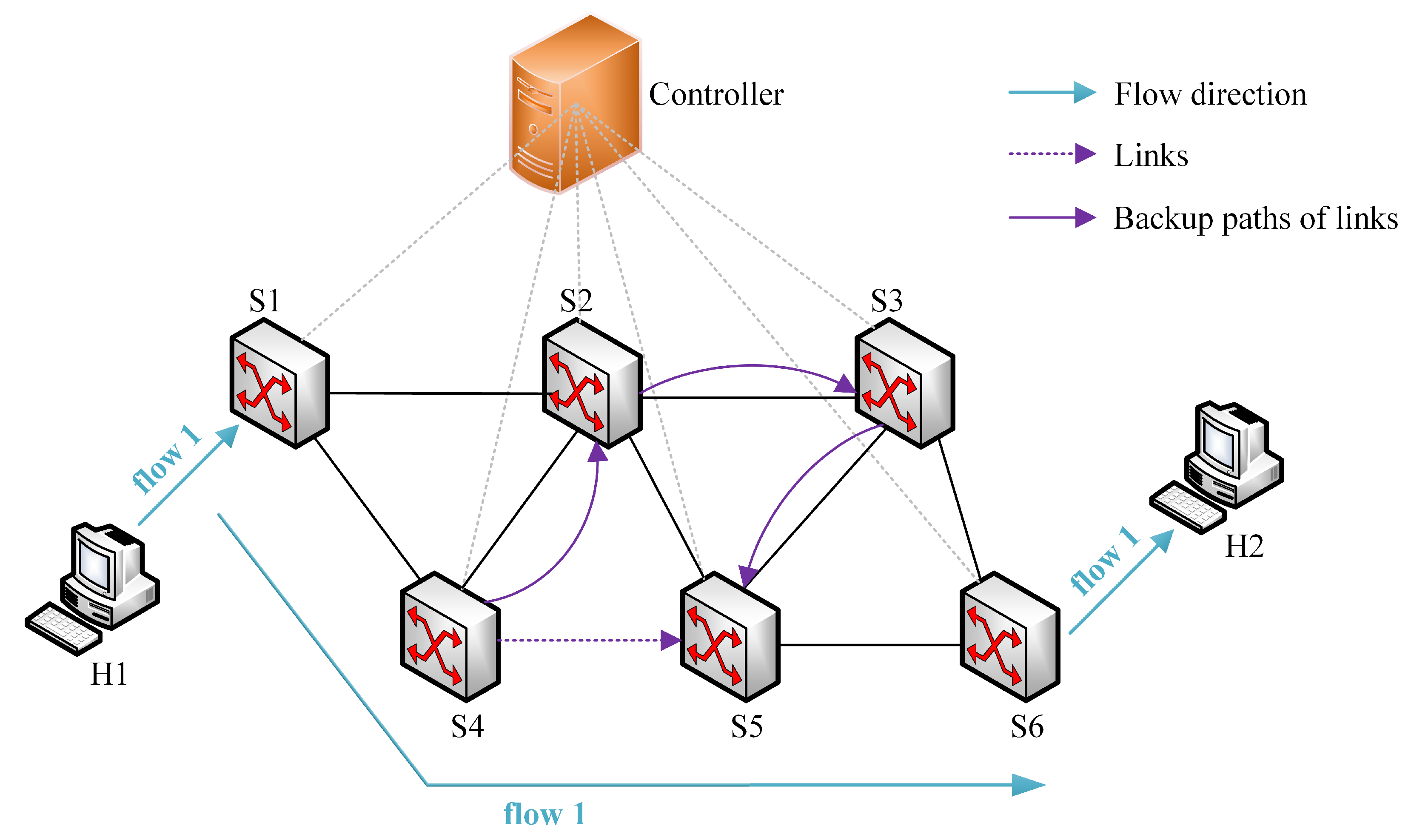
Before the introduction of OpenFlow groups, including fast failover groups, many studies adopted recovery mechanisms to handle this issue. Kim [33] et al. computed routing paths using VLAN. Sharma [34] et al. compared their fast failover system with the NOX controller’s learning switch, learning PySwitch, and routing mode. Nguyen [35] et al. implemented fault tolerance in wide area networks (WANs) using SDN, as routing protocols such as BGP and OSPF encounter severe problems during failures. For instance, while BGP has a longer path convergence time, OSPF has a longer recovery time. Li [36] et al. developed a recovery method that reduces path computation time by using a locally optimal fault-tolerance method. Zhang [37] et al. considered link failure and controller placement issues, studying network resilience of OpenFlow-based centralized networks. They first formulated controller placement metrics and failure types including links, switches, and failures between switches and controllers. They then performed resilience analysis for the centralized network architecture. Experimental results showed that controller location significantly affects the resilience of the network. Lee [38] et al. focused on real-time flows, considering their own fault tolerance limitations, and used adaptive path recovery. They implemented a multi-constraint path-finding algorithm that can reroute traffic according to time budgets. In the research by Tajiki [39] et al., the authors considered the fault recovery of service function chains. Based on the service requirements of each service, they used recovery as a type of fault-aware routing. Liang [40] et al. designed a backup path selection algorithm for the network that achieves low interruption rates for flows based on a recovery mechanism and heuristic algorithm.
Some studies have also considered this reliability. In the research by Yuan [41] et al., they designed a system based on the Byzantine model to tolerate faulty switches to enhance reliability. Moreover, Song [42] et al. focused on the reliability of the control path, which is an important consideration for out-of-band controllers whose network view might be affected by data plane failures. In addition, Bhatia [43] et al. considered reliability in an SDN-enabled VANET environment. They adopted a network coding-based approach for reliable data propagation. Narimani [44] et al. proposed a reactive method for fault tolerance in hybrid SDN. They utilized a stochastic network calculus framework for dynamic resource allocation in MEC systems. This method ensures QoS while addressing network faults reactively, aligning network resource management with current network conditions and demands.

3. Motivation

In this section, a simple network scenario is presented to explain the motivation of this paper. Based on the analysis of this scenario, we briefly explain the advantages and disadvantages of the proactive and reactive schemes. To address existing drawbacks, we propose FAPR, a single link failure recovery strategy that combines proactive and reactive schemes with the awareness of flow types.

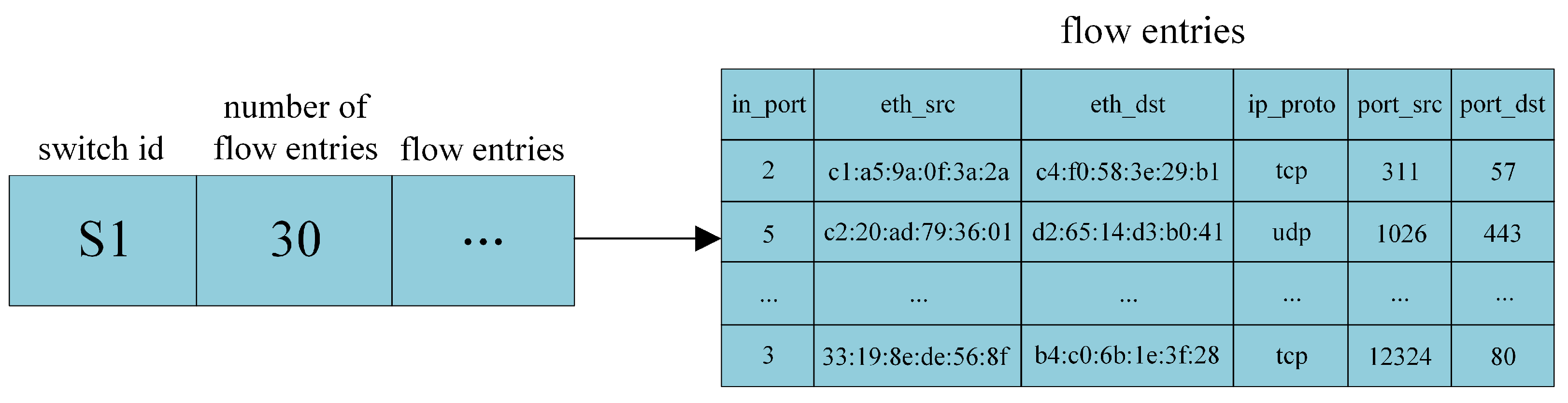
3.1. Concept of Flow

Before giving examples, we first introduce the concept of flow. A flow can be defined as any combination of tuples involved in the OpenFlow protocol, such as source and destination IP addresses, Ethernet addresses, and transport layer protocols [45]. For simplicity, in this paper, we choose source and destination IP addresses, transport layer protocol, and source and destination port numbers of the transport layer to define a flow. In other words, as long as packets have the same five tuples, these packets are considered to belong to the same flow. Note that the five tuples used in this paper are all listed in Table 1. In the data plane, the SDN switch forwards flows according to the flow table, which contains several flow table entries. If a packet of a flow matches a flow table entry, then it executes the corresponding action of the flow table entry, otherwise it triggers the default flow table entry, which forwards the packet to the controller for processing.

3.2. Analysis of Two Classical Schemes

The proactive scheme involves pre-calculating the backup paths and installing them in the switches in advance, so that packets can automatically switch to backup paths when a link failure occurs. To explain the principle of the protection scheme explicitly, an example is shown in Figure 1. Assume host H 1 sends a flow, i.e., flow 1, to host H 2 , and its primary path is supposed to be S 1 - S 4 - S 5 - S 6 . The potential failures are labeled in the figure in different colors, represented by red, purple, and green dashed lines, which correspond to failures of links S 1 - S 4 , S 4 - S 5 , and S 5 - S 6 , respectively. The backup paths for these three links are supposed to be S 1 - S 2 - S 4 , S 4 - S 2 - S 5 , and S 5 - S 3 - S 6 , respectively. Since the focus of this paper is to solve single link failures, then these link failures will not occur simultaneously. As the proactive scheme is executed, these three backup paths are installed in the corresponding switches in advance, with bandwidth and other resources reserved. It is obvious that this scheme will consume a significant amount of internal resources in the switches. Moreover, if the network scale increases, the numbers of switches and flows increase as well, which may consume more internal resources of switches (for example, in this case, the required number of TCAMs will increase). In extreme cases, this can exhaust the resources of the switch, which can ultimately lead to poorer results of link failure recovery.
Additionally, the proactive scheme may lead to conflicts among flow table rules and forwarding loops. Take Figure 1 as an example. Assume that link S 1 - S 4 fails, then the backup path S 1 - S 2 - S 4 is enabled. Unfortunately, if link S 4 - S 5 fails immediately afterwards, the corresponding switches will enable the backup path S 4 - S 2 - S 5 . In this situation, for the same flow, S 2 installs a flow rule to forward packets to S 4 , while S 4 installs a flow rule to forward packets to S 2 , then the forwarding loop emerges, which can decrease the quality of service without doubt. To overcome the problem mentioned above, the flow table entries for backup paths must be installed to avoid forwarding loops.
On the contrary, the reactive scheme does not require pre-installing backup paths. Instead, it calculates and deploys the backup path in real time after a failure occurs, with the involvement of the controller. Take Figure 2 as an example. The primary path of flow 1 is still S 1 - S 4 - S 5 - S 6 . If the link S 4 - S 5 (indicated by the purple dashed line) fails, the switch will first upload this information to the controller. As a response, the controller immediately calculates the backup path for the failed link, and updates or installs the flow rules on the corresponding switches according the current global network view. Suppose the backup path for link S 4 - S 5 at this time is S 4 - S 2 - S 3 - S 5 , indicated by the purple solid line, then switch S 4 needs to update the flow rule (to forward packets to S 2 instead of S 5 ), and switch S 2 needs to install a new flow rule (to forward packets to S 3 ). It can be inferred that the reactive scheme can save TCAMs in switches, while requiring a longer recovery time, including the time for the switch to upload failure information, the time for the controller to calculate the backup path, and the time to update and install flow rules. As a result, the reactive scheme may not be suitable for carrier-grade networks that require the failure recovery time to be less than 50 ms.
No matter whether the proactive scheme or the reactive scheme is adopted, backup paths need to be calculated before or after failures. Generally, we always find out the shortest path and switch all the flows affected by the failure over to the same backup path. However, the available resources of the backup path are limited, such as bandwidth. If the required bandwidth of flows exceeds the threshold of the backup path, it may cause flow congestion or interruption, which finally affects the whole network performance. As a result, it is necessary to propose a failure recovery scheme that can make full use of both proactive and reactive schemes, and avoid the flow overload simultaneously.

3.3. Proposed Scheme

In this paper, we propose the FAPR scheme, which combines the proactive and reactive schemes to exploit their advantages, and allocates suitable backup paths for different types of flows to reduce the possibility of flow congestion or interruption in the subsequent forwarding process and improve the quality of network service. Take Figure 3 as an example, where host H 1 sends three flows, i.e., flow 1, flow 2, and flow 3, to H 2 , and the primary path of these three flows is assumed to be S 1 - S 3 - S 5 . FAPR calculates multiple backup paths for each link of the topology. For instance, the proposed scheme calculates three backup paths for link S 1 - S 3 , which are marked with red, purple, and green solid lines, namely S 1 - S 2 - S 3 , S 1 - S 6 - S 7 , and S 1 - S 4 - S 5 - S 3 , respectively, and these three backup paths are stored in the controller. In addition, we adopt the pro-VLAN [19] based on the protection mechanism to install the backup paths in the corresponding switches in advance simultaneously. When S 1 - S 3 fails, the switch will automatically switch to the pre-installed backup path (which is calculated and installed by pro-VLAN), and the controller will receive the failure notification information simultaneously. As the three flows walk through the link S 1 - S 3 , they are all affected by the failed link. However, the three flows are different in traffic characteristics: one flow may require a wider bandwidth, while another flow is more sensitive to delay. FAPR analyzes the peculiarity of each flow and each backup path, and chooses the most suitable backup path for each flow. Moreover, the controller is responsible for removing overlapping paths to avoid forwarding loops. For instance, one backup path for link S 1 - S 3 is path S 1 - S 4 - S 5 - S 3 , as shown in Figure 3. If the backup path is assigned for any flow mentioned above, then the forwarding path after the link failure is supposed to be S 1 - S 4 - S 5 - S 3 - S 5 , in which a forwarding loop exists. In this situation, the controller should remove the forwarding loop and update the forwarding path to be S 1 - S 4 - S 5 . After the update of flow rules, the packets shift paths again. In conclusion, FAPR contains two path shifts in total. The first shift to the pre-calculated backup path (by pro-VLAN) is at high speed to reduce the number of lost packets to the best. The second shift to the backup path is realized by the controller to reduce the possibility of flow congestion and interruption.
In FAPR, the pro-VLAN scheme not only recovers from link failures quickly, but also reduces the use of storage space of switches effectively. Simultaneously, the controller can adopt multiple algorithms to calculate multiple backup paths for each link in advance and store them in the controller. When a link fails, the controller allocates the most suitable backup path according to the characteristic of the affected flow. As a result, the FAPR scheme avoids the issue of excessive resource usage of the proactive scheme and the excessive delay of the reactive scheme simultaneously.

4. Design of Proposed Scheme: FAPR

In this section, we will provide a detailed description of the FAPR scheme. As the proposed scheme combines both the protection and restoration schemes, we will introduce the proactive part and reactive part first. Moreover, the network model, algorithms, and formulations will be described as well.

4.1. FAPR Overview

As mentioned before, our proposed link failure recovery scheme is called flow-aware pro-recover (FAPR). Note that “flow-aware” represents that our proposed scheme is “flow-aware”, which means that it allocates backup paths based on the characteristics of flows. “Pro-recover” represents that our proposed scheme combines the advantages of both the “proactive” scheme and “reactive” scheme. More specifically, “pro” refers to the pro-VLAN method [19]. The overall architecture of FAPR is shown in Figure 4, which is divided into two main parts. The proactive part mainly includes the data collection module and the backup path generation module, and the reactive part consists of five modules: data collection, backup path generation, failure detection, flow analysis, and backup path allocation.
In the proactive part, the pro-VLAN method from our previous research is adopted, which will be discussed in detail in the following subsection. In the reactive part, the backup paths are pre-calculated and stored in the controller, which can reduce the delay caused by calculating the backup paths after failures. Moreover, the selection of backup paths in FAPR is more sophisticated. Most current failure recovery schemes only consider the basic usability of backup paths for the affected flows, without taking into account potential issues flows might encounter in the following forwarding process from a global perspective. As stated in Section 3, FAPR assigns the most suitable backup path for each flow affected by the faulty link, and different flows are often assigned to different backup paths, avoiding the phenomenon that all the flows forward along the same backup path after failures. In the architecture, the data collection module collects network information and passes it to the backup path generation module to generate and save backup paths. When a link fault occurs, the failure detection module of the reactive part can detect the malfunction and pass the flow information to the flow analysis module for traffic classification. Finally, the backup path allocation module assigns the backup paths adaptively based on the result of classification and analysis of backup paths. The details of all modules in both reactive and proactive parts will be explained in the following subsections.

4.2. Proactive Part

In the proactive part, the pro-VLAN method based on the protection mechanism is adopted. As introduced in Section 2.1, the fast failover group table is proposed in the OpenFlow protocol version 1.1, providing the function of fault tolerance, and multiple methods based on the proactive scheme basically use this type of group table for fast link failure recovery. Traditional proactive schemes calculate backup paths for specific flows. It can be inferred that, when the number of flows increases, the switches’ TCAMs will also be quickly consumed.
Unlike these methods, the pro-VLAN method cleverly disassociates the flow table and group table entries from flows. Specifically, for each link of the topology, it calculates a backup path and assigns a globally unique VLAN ID, so the backup path for each link is prepared before a flow is generated, and the corresponding flow table and group table entries can be installed in the respective switches in advance. When a link failure occurs, the switches will automatically apply the actions in the group table and tag the affected flow with the corresponding VLAN ID. These packets with specific VLAN IDs will be automatically switched to the backup path, and execute the actions of flow table entries whose match fields are the link’s VLAN IDs. Before leaving the backup path, the VLAN ID tag information is erased, thus returning to the normal forwarding afterwards. The pro-VLAN method can recover from link failures at a high speed and does not require modification of any hardware or protocols. Moreover, it can significantly reduce the consumption of TCAMs in switches, as forwarding table entries are independent of flows. Regardless of the scale and the diversity of the network, it can keep the number of backup flow table entries in switches stable, as this number is only related to the number of links on each switch.
As shown in Figure 4, this part mainly consists of the data collection module and the backup path generation module. The pro-VLAN method obtains relevant information from the network and installs corresponding rules into the switches by assigning a VLAN ID to each link after generating the backup path. More detailed information about this method can be found in our previous work [19], and is not described here any more.

4.3. Reactive Part

The reactive part is the focus of this paper and includes five modules in total: data collection, backup path generation, failure detection, flow analysis, and backup path allocation modules, and we will provide a detailed description of each module below.

4.3.1. Data Collection Module

The main function of the data collection module is to gather network information from the data plane, and then process the collected information to realize standardization, which makes subsequent processing more convenient. The standardization of network information by this module is the foundation for the backup path generation module to calculate the backup path.
In the FAPR scheme, the information collected by the data collection module is divided into three parts, namely, switch information, link information, and events sent from the switch to the controller. More specifically, the standardized switch information includes the switch’s ID and the flow table entries stored in it, as shown in Figure 5. The standardized link information includes the ID of the source and destination switches of the link, the total bandwidth of the link, and the bandwidth that has been used, as shown in Figure 6. The events sent from the switch to the controller contain the packet information of flows, namely, a flow table entry, as shown in the right part of Figure 5. An event also contains the information related to the OpenFlow protocol version, parser, and timestamp involved. This module runs multiple times (for instance, when a port-status message is generated) and the information collected each time may not include all the items of the standardized information.

4.3.2. Backup Path Generation Module

The backup path generation module is a very important part of FAPR, as it calculates the backup path for each link in the data plane based on the information gathered from the data collection module. Firstly, this module obtains all the link information and generates the network topology. The link information obtained is standardized, which means that the controller can find out the source and target switches of each link. Secondly, this module calculates multiple backup paths for each link, and the algorithm used here is based on the K-shortest path algorithm. In the example shown in Figure 3, we take K = 3, that is, we calculate in total three backup paths for each link. Note that not all links have three backup paths. In a network topology, when compared with the links in the center, the links on the edge usually correspond to lower degrees and fewer backup paths, even fewer than three backup paths.
Finally, when all the backup paths are generated, this module stores all the calculated backup paths in the controller. When a link failure occurs, subsequent modules analyse the characteristics of the affected flow, choose the most suitable backup path and install the proper flow rules on the corresponding switches.

4.3.3. Failure Detection Module

The failure detection module connects the switch to the controller, and its role is to perceive link failures in the network, standardize the information returned by the data collection module, and pass to subsequent modules for processing. This module is in real-time monitoring status, which can promise to respond to network events in a timely manner upon a link failure, and invoke the data collection module to send data retrieval requests to the corresponding switches. After receiving the requests, switches will return detailed information about the faulty link. In addition, this module can also retrieve other data, such as the original path of the flow. Note that the flow analysis module is posterior to the failure detection module, and the former can obtain switch IDs of the faulty link and the flow entries in these switches from the standardized information and other data mentioned above.

4.3.4. Flow Analysis Module

The flow analysis module is the most crucial module of FAPR’s reactive part, and its role is to filtrate the flows that are affected by the link failure, and analyze their characteristics to allocate suitable backup paths. In a real network, the vast majority of flows are generated by an application at the application layer. Moreover, each flow corresponds to a pair of port numbers to identify different types of applications, and uses either a transport control protocol (TCP) or a user datagram protocol (UDP) as the transport layer protocol. As a result, FAPR distinguishes different types of network services by analyzing transport layer protocols and port numbers. After identifying the types of network services, FAPR will allocate the most suitable backup paths for each flow. For example, file transfer applications have a higher demand for bandwidth, while remote desktop applications, real-time chat programs, video conferences, and online games are generally more sensitive to latency.
In Section 4.3.3, we mention that the failure detection module transmits the standardized information of the failed link and other data to the flow analysis module, which contains the information of flows affected by the failure (in the form of flow table entries), the original paths of these flows, and so on. The flow analysis module extracts important tuples from these flow table entries, including the transport layer protocol and port numbers of each flow, and determines the type of network service. Moreover, the application type and original path of each flow, along with other information, will be sent to the backup path allocation module for processing.

4.3.5. Backup Path Allocation Module

The backup path allocation module is the final step in the reactive part of the FAPR scheme for link failure recovery, and is responsible for allocating backup paths and installing the corresponding flow table entries into the switches for flows affected by link failures. Firstly, we need to obtain the network performance metrics of backup paths. For example, we can utilize the data collection module to obtain the information of each link, in order to calculate the remaining bandwidth and delay. Secondly, we can allocate the most appropriate backup path for each flow according to its application type and the network performance metrics of alternative backup paths. Thirdly, we need to compare the original primary path and the chosen backup path for each flow to find out whether two paths compose a forwarding loop. If so, the backup path must be optimized to remove the circle to avoid broadcast storm. The corresponding algorithm will be explained in Section 4.5.3. Finally, the flow table entries are installed into the switches, and then packets can forward along the backup path to the destination that satisfies the QoS required by the flow.

4.4. Network Model

In this paper, for ease of processing, the network topology of the data plane is represented by a directed graph, G = ( V , E ) , where V is the set of switches and E is the set of links. For switch i and switch j, e i j represents the link between them. f represents a flow, and F i j = f i j 1 , f i j 2 , f i j n represents the flows on link e i j . b represents a backup path, and B i j = b i j 1 , b i j 2 , b i j k represents the set of all backup paths for link e i j . Table A1 lists all the basic mathematical symbols involved in the network model of this paper and their corresponding definitions.

4.5. Algorithms and Formulation

In this section, we will introduce the algorithms and formulas involved in the FAPR scheme, including the broadcast storm suppression algorithm, optimized K-shortest paths algorithm, backup path overlap removal algorithm, bandwidth estimation method, latency estimation method, and the formulation of backup path allocation.

4.5.1. Broadcast Storm Suppression Algorithm

Broadcast storm refers to a situation in which a broadcast message in the network is repeatedly received and forwarded, and circulates for a long time, leading to network congestion, increased delay, and performance degradation. In SDN, many broadcast messages exist in the network, and SDN switches cannot handle this type of message due to a lack of intelligence. As a result, suppressing broadcast storms is a very important task in SDN, and can reduce the disorderly spread of broadcast messages in the network, improving network performance and stability.
In the FAPR scheme, we have designed a relatively simple but efficient broadcast storm suppression algorithm. The proposed algorithm does not require any extra man-made interference and does not disrupt the transmission of data packets in the network, which maximize the application value of the algorithm in real network scenarios. The complete algorithm is shown in Algorithm 1. The input to the algorithm is an ARP packet, p f , of a flow, and the output is a signal indicating whether to normally forward this packet. We use the following four tuples, including source and destination MAC addresses, destination IP address, and ingress port, to determine whether the current ARP packet is duplicate or not. If so, we guide the switch to drop the same packet, otherwise we forward it normally. Since we need to traverse a nested dictionary, the time complexity of Algorithm 1 is O ( n 2 ) .
Algorithm 1 Broadcast storm suppression algorithm
Require: 
an ARP packet p f ;
Ensure: 
a signal indicating whether to forward p f ;
  1:
Get the ARP type of p f , denote it as T p ;
  2:
Get the source mac, destination mac, destination ip and input port of p f , denote it as mac_src, mac_dst, ip_dst and in_port;
  3:
if  T p is ARP request and mac_dst is broadcast address then
  4:
      if mac_src is in record then
  5:
            if ip_dst is in record [mac_src] then
  6:
                 if value in record [mac_src, ip_dst] is the same as in_port then
  7:
                       Add a rule to drop packets that are the same as p f , and drop p f ;
  8:
                 else
  9:
                       Forward;
10:
                 end if
11:
            else
12:
                 Add ip_dst and in_port to the record [mac_src], then forward;
13:
            end if
14:
      else
15:
            Add the key-value pair of mac_src and ip_dst to in_port as a new record;
16:
            Then forward;
17:
      end if
18:
else
19:
      Forward;
20:
end if

4.5.2. Optimized K-Shortest Paths Algorithm

In the FAPR scheme, we use the concept of the K-shortest path algorithm to calculate backup paths for each link. The K-shortest path algorithm is a shortest path algorithm based on Dijkstra’s algorithm, which can find the total number of K-shortest paths from the starting point to the endpoint. The core idea of the K-shortest path algorithm is to use Dijkstra’s shortest path tree to continuously adjust the path of the tree until the K-shortest paths are found [46]. Since the K-shortest path algorithm needs to adjust the path multiple times, its time complexity is relatively high. As a result, FAPR optimizes the algorithm to increase computational efficiency through reducing the coselection rate among K paths. Based on the considerations mentioned above, we propose the optimized K-shortest path algorithm including the following three steps. If a binary heap is employed for optimization in Step 2 below, the time complexity of the algorithm can be reduced to O ( k n ( m + n ) l o g n ) , where k is the number of backup paths of each link, m is the number of edges, and n is the number of nodes.
Step 1 Pre-processing.
The Floyd algorithm or Johnson algorithm can be used to calculate the shortest path between any two points in advance and store it in a matrix, especially for dense graphs. Whenever a shortest path from the starting point to the endpoint needs to be calculated, we just need to look up the matrix instead of recalculating, thus improving the efficiency of the algorithm.
Step 2 Heap optimization.
When executing Dijkstra’s algorithm, it is necessary to select a node closest to the starting point from the set of unprocessed nodes each time. If linear search is used, the time complexity is O ( n 2 ) , where n is the number of nodes, and the time complexity is unacceptable for large-scale graphs. Therefore, we can use the heap data structure such as binary heap or Fibonacci heap to maintain the set of unprocessed nodes, and select the node closest to the starting point from the heap for processing. The time complexity can be reduced to O ( ( m + n ) l o g n ) (using binary heap), where m is the number of edges and n is the number of nodes.
Step 3 Pruning.
In the K-shortest path algorithm, it is possible to record the length of the current path in the process of reverse search. If the length of the current path has already exceeded the longest path among the K-shortest paths, the search can be stopped immediately. By this means, the algorithm can avoid searching too many paths to improve the efficiency. In addition, the problem of overlapping among the calculated K-shortest paths is quite notable in some cases. To tackle this issue, we are inspired by the concepts found in Suurballe’s algorithm. Suurballe’s algorithm is famous for finding two disjoint shortest paths in a graph, achieved by adjusting the weights of the edges in the graph after identifying a shortest path. By incorporating this idea into the K-shortest path algorithm, we modify the weight of each edge after a shortest path is found, by adding a large constant. Consequently, when we run the Dijkstra algorithm again to find the next path, the newly calculated path tends to avoid edges used in the previous path, resulting in a significant reduction in the coselection rate.

4.5.3. Backup Path Overlap Removal Algorithm

As mentioned before, a loop may exist between the original path and its corresponding backup path, which needs to be removed. The algorithm for removing overlapping paths is shown in Algorithm 2. The input of this algorithm is the set of flows, F i j , on the link e i j , the set of flows’ original paths, O i j , f , and the set of backup paths, B i j , f , and the output is the set of optimized backup paths, B i j , f , for each flow. For each flow, f i j , on the link e i j , we first obtain its original forwarding path, o i j , f , and all the K backup paths, b i j , f , allocated for it. Second, we compare the original path and one of its backup paths to delete their overlapping parts and to compose the new backup path, b i j , f . Finally, we obtain the set of optimized backup paths, B i j , f . For each flow, it is necessary to traverse the backup paths of the current link and compare them with the flow’s original path. Consequently, the time complexity of Algorithm 2 is O ( k n ) , where k is the number of backup paths of each link and n represents the scale of input flows.
Algorithm 2 Backup path overlap removal algorithm
Require: 
F i j , O i j , f , B i j , f ;
Ensure: 
B i j , f ;
  1:
for flow f i j in F i j  do
  2:
      Compare b i j , f with o i j , f ;
  3:
      if overlap path exists then
  4:
            delete overlap path;
  5:
            Add b i j , f to B i j , f ;
  6:
      else
  7:
            Add b i j , f to B i j , f ;
  8:
      end if
  9:
end for

4.5.4. Formulation of Backup Path Allocation

As mentioned before, the FAPR scheme strives to assign the most appropriate path for each flow affected by link failures, in order to mitigate the probability of congestion or interruption after failure recovery. The problem of appropriately assigning backup paths can be seen as a backup path assignment problem, which has been detailed in Section 4.3.5. In this subsection, we try to formalize this issue.
Firstly, we present the definitions of network congestion and flow interruption. If the remaining available bandwidth of the backup path is not sufficient to support the required bandwidth of a flow after failures, congestion will occur. Even in severe cases, the interruption of flows may happen, and the definition of flow interruption for a backup path is shown in Formula (1).
Γ f i j n + Γ F m n o + n n N Γ f i j n i m n n Γ e m n , e m n b i j , f n
Assume that the link e i j fails, with a total of N flows being affected. Among all the affected flows, f i j n is the n-th flow passing by link e i j , and Γ f i j n represents the size of this flow, i.e., the bandwidth it requires. b i j , f n represents the backup path for the flow f i j n , and e m n represents any link of b i j , f n . F m n o represents the set of flows transmitted normally on link e m n before link failures, and Γ F m n o represents the sum of the bandwidths required by these flows. Γ f i j n represents the bandwidth required by a single affected flow other than f i j n , and i m n is a binary quantity indicating whether a flow will pass through link e m n , with 1 indicating yes, and 0 indicating no. Therefore, n n N Γ f i j n i m n n represents the sum of the bandwidths required by all the affected flows that pass through link e m n , excluding f i j n . On the other hand, Γ e m n is the total bandwidth of link e m n . Thus, the sum of the three parts on the left-hand side of the inequality is the total bandwidth required by all flows passing through link e m n . When link e i j fails, any link, e m n , of the backup path b i j , f n for any flow, f i j n , must satisfy Formula (1). Otherwise, the link may face congestion due to insufficient bandwidth, and the flow f i j n might experience interruption.
For each link, e i j , of the topology, we generate a set of backup paths, B i j . When the link e i j fails and the n-th flow, f i j n , on this link is affected, a backup path, b i j , f n , is selected from B i j , and the chosen backup path should satisfy the following two objective functions.
min size F i j size F i j
max n N P b i j , f n
In Formula (2), F i j represents the set of flows that is interrupted after the failure recovery of link e i j . F i j represents the set of flows on link e i j . The s i z e ( ) function is used to find the size of the set. The objective of this formula is to minimize the flow interruption rate. In Formula (3), P ( ) represents the suitability, i.e., a matching degree between a flow and a backup path, with a value ranging from 0 to 1. The higher the extent to which this backup path satisfies the feature indicators of this flow, the higher is its suitability. The objective of this formula is to maximize the total suitability of the backup paths for all flows.

4.5.5. Bandwidth Estimation Method

In SDN networks, link bandwidth can be obtained via the OpenFlow protocol or through third-party measurement technology, such as sFlow (Version 5). In the FAPR scheme, we obtain link bandwidth through the OpenFlow protocol. The bandwidth of a link is determined by the capabilities of its two endpoints. Therefore, we can obtain the link bandwidth from traffic information of ports. In the OpenFlow protocol, the traffic information contains the statistical information of ports, flow tables, group tables, etc., and we can obtain the number of packets sent and received, and the number of bytes during the statistical time. Finally, the link bandwidth can be calculated.
Assume that at time t 1 , the controller sends the first port request message to a switch that connects to the target link, and the statistical message returned by the switch contains the number of bytes sent and received by port S 1 at time t 1 , and the time of duration is d 1 . Assume that at time t 2 , the controller sends the second port request message to the switch again, and the number of bytes and the time of duration are S 2 and d 2 , respectively. As the result, the used bandwidth of this port, or the used bandwidth of this link in this period of time, represented by U B t 1 t 2 , can be calculated, and the corresponding formula is shown as follows:
U B t 1 t 2 = 8 S 2 S 1 t 2 + d 2 t 1 d 1
The remaining bandwidth of a link can be calculated through subtracting the used bandwidth from the maximum bandwidth of the port (link). Similarly, the statistical traffic of flow table entries or group table entries can be calculated. Note that the data of the remaining bandwidth will not only be used in the backup path allocation module, but also can support subsequent traffic optimization projects such as load balancing.

4.5.6. Latency Estimation Method

Even though the estimation of latency is easy to realize for end hosts, it is challenging for switches in SDN networks. This is because SDN switches can only purely forward packets with almost no intelligence, and all actions such as requests are directed by the controller. In the FAPR scheme, we adopt a theoretical method to measure the latency between any two switches in the network.
Assume that at time t A , the controller sends a packet to switch A. The data segment of this packet carries the timestamp when the message is issued, and its action instructs the switch to flood it. After a while, switch B receives the packet flooded by switch A, while the packet cannot match the any flow table entry, and thus is uploaded to the controller. After receiving this packet, the controller records the current time, t B , and calculates the time difference, t B t A . It can be inferred that this time difference approximates the propagation delay from the controller to switch A, from switch A to switch B, and finally from switch B back to the controller. Next, assume that at time t B , the controller sends a similar packet to switch B. Similarly, when this packet is uploaded via switch A, the controller records the current time, t A , and calculates the second time difference, t A t B . By combining the two metrics together, we can obtain twice the sum of the round-trip time (RTT) from the controller to switch A, the RTT from the controller to switch B, and the RTT from switch A to switch B. We will denote this sum as R T T 2 t o t a l , as shown in Formula (5).
R T T 2 t o t a l = t A t B + t B t A
In order to deduce the delay between two switches, we need to subtract the delay from each switch to the controller from the sum mentioned above. As a result, the delay between the control plane and data plane should be calculated. Assume that at time t r , the controller sends a simple request-response message to switches A and B simultaneously, and the switches will respond immediately upon receiving it. Suppose the controller receives the response messages from the two switches at times t r A and t r B , respectively, then the total RTT from the controller to switches A and B, denoted as R T T 2 c s , can be shown as follows:
R T T 2 c s = t r A t r + t r B t r
Therefore, the latency from switch A to switch B, which we will denote as L s s , is shown as follows:
L s s = R T T 2 t o t a l R T T 2 c s 2 = t A t B + t B t A t r A t r B 2 + t r

5. Performance Evaluation

In this section, we will describe the simulation environment, comparison methods, and simulation results of the FAPR scheme.

5.1. Simulation Environment

In this experiment, we install a Linux virtual machine program on the Windows 11 system, and then conduct simulations in the Mininet emulation environment under the Linux system. Mininet is a network emulator that creates a network of virtual hosts, switches, controllers, and links. It runs real network applications, using the Linux kernel and network stack, enabling easy transition of developed code to real systems for deployment, and its switches support OpenFlow for highly flexible custom routing and SDN. The virtual machine is allocated 8 CPU cores and 8 GB RAM. The selected controller is Ryu, which is based on Python, and the network topology used in the simulation experiment is a 6-pod fat-tree topology, as shown in Figure 7. It consists of edge layer switches that connect hosts, aggregation layer switches that consolidate traffic from the edge layer, and core layer switches responsible for routing traffic between different aggregation layers. Each Pod includes edge and aggregation layer switches and their interconnections, ensuring high scalability and redundancy of the network. The controller, located on the control plane, is not shown here but is connected to the network. Excluding the hosts, there are a total of 45 nodes, and the size and complexity of the topology are sufficient to meet the requirements of the experiment. The experimental traffic in the network is generated by i P e r f 3 , and the types of flows mainly include bandwidth-demanding and latency-sensitive types. Moreover, for convenience of the experiment, the number of backup paths calculated and stored in the backup path generation module (introduced in Section 4.3.2) is set to be 3.

5.2. Comparison Methods

In order to verify the effectiveness of the FAPR scheme, we compare it with other methods in the simulation experiment. Since the FAPR scheme combines protection with recovery mechanisms, we compare it with a standard proactive method and a reactive failure recovery method. More specifically, the proactive scheme refers to the pro-PATH method introduced in [19], which installs a backup path in switches for each flow in advance, and shifts to the backup path autonomously when a link failure occurs. The reactive scheme calculates a bandwidth-optimal path for the failed link when a link failure occurs, and switches all affected flows to this backup path.

5.3. Simulation Results

In the following experiments, we select two hosts in two pods that are farthest apart in the fat-tree topology, one as the server for i P e r f 3 and the other as the client for i P e r f 3 . As stated in Section 5.1, there are two types of flows. The number of flows increases from 2 to 34, including 2, 4, 6, 10, 16, 24, and 34 flows, and the types of flows include the bandwidth-demanding and latency-sensitive flows. For instance, when the number of flows is set to be 2, there is one bandwidth-demanding flow and one latency-sensitive flow. Note that the amount of data transmitted is sufficient to meet the requirements of the experiment. Considering that the network topology we adopt belongs to a relatively small network scale, we reduce the size of each packet as well. More specifically, we change the default TCP packet size of i p e r f 3 from 128 KB to 1 KB, and the UDP packet size from 8 KB to 1 KB, which is more convenient for us to infer the recovery time from the number of lost packets. In order to eliminate the errors in the simulation experiment, we repeat each group of experiments, i.e., one method for the same number of flows, for seven times in total, exclude outliers, and calculate the mean value. Note that, in each group of experiments, we keep the network topology, the pairs of hosts, the number of flows, and the failed link unchanged, to avoid result bias to the best extent. Last, but not least, in each set of experiments, the entire experimental environment is reset to avoid possible interference from data caching.

5.3.1. Failure Recovery Time

Figure 8 shows and compares the link failure recovery time among three schemes, i.e., the FAPR, and proactive and reactive schemes. For the FAPR and proactive schemes, the failure recovery time refers to the duration from the onset of a link failure to the moment when the switch automatically transitions to a backup path, allowing the flow to continue forwarding. In contrast, for the reactive scheme, it denotes the time from the initiation of a link failure to when the switch receives and implements the backup path dispatched by the controller, enabling the flow to resume forwarding. It can be observed that the failure recovery time of the FAPR and the proactive schemes is significantly less than that of the reactive scheme, as the latter requires the intervention of the controller to participate in the recover after link failures. More specifically, the failure recovery time of the FAPR and the proactive schemes is generally within 20 ms, while the reactive scheme can reach more than 60 ms, and it may be even higher if the communication between the switch and the controller is in heavy burden. At the same time, it can also be found that the failure recovery time in these three schemes is not significantly related to the number of flows. In addition, Figure 9 elucidates the distribution of failure recovery times, revealing the FAPR and proactive schemes’ stable performance, as evidenced by their tight interquartile ranges (IQRs). This stability is due to the automated path switching by the switch, precluding controller involvement. In contrast, the reactive scheme’s broader IQR and outliers reflect its variability, arising from the necessity of controller–switch communication post-failure. This round-trip communication is subject to latencies from network congestion and controller processing, influencing the recovery time’s unpredictability, which is particularly critical in time-sensitive network environments.

5.3.2. Interruption Rate

Figure 10 shows the interruption rates of different schemes as the number of flows changes. Since there are no tools to directly measure the interruption rate of a flow, we use a combination of iperf3, Wireshark, and Linux system’s “netstat” and “ss” commands to judge whether a flow is interrupted, and thus estimate the interruption rate of a flow. Specifically, after the link failure is recovered, we let all the flows continue to transmit for a few seconds, and then stop and count statistical data. Note that when switching forwarding paths, packets loss may also occur, and we only count the number of lost packets after the link failure has been recovered. For TCP flows, if retransmissions occur, then these flows are considered to be interrupted. The “netstat” and “ss” commands are used to monitor TCP retransmissions. For UDP flows, if there are packet losses or excessive delays, these flows are considered to be interrupted. We use i p e r f 3 to monitor UDP packet loss and Wireshark to assist in monitoring abnormal delays in UDP packets.
As shown in Figure 10, when the number of flows increases, the flow interruption rates of the three schemes increase as well. However, under the same experimental conditions, the flow interruption rate of the FAPR scheme is always lower than the other two schemes. Among these three schemes, the proactive scheme corresponds to the highest flow interruption rate. This can be explained by the fact that the proactive scheme deploys flow rules in advance in switches, and does not consider the real-time network view. When link failure occurs, flows may forward along multiple backup paths that contain the same link, leading to congestion or interruption. Compared with the proactive scheme, the reactive scheme considers the real-time view of the network, so it performs better. Unlike the other two schemes, the FAPR scheme has the lowest interruption rate by classifying different types of flows and assigning the most suitable path to each flow, thus avoiding over-concentration of flows.
In addition to the interruption rate, the FAPR scheme can also improve the quality of service in the network, because it assigns the most suitable backup paths to flows with different characteristics. However, we cannot quantify this indicator well in a simulation environment, because it is difficult for us to simulate multiple different applications and design network indicators corresponding to different types of applications. Nevertheless, it is not difficult to infer that, in a real complex network with various types of traffic, assigning adaptive backup paths to flows with different needs after a link failure can indeed improve indicators of the network.

5.3.3. Number of Backup Flow Rules

Figure 11 and Figure 12 show the numbers of backup flow rules required by the three schemes. The number of backup flow rules is the number of forwarding rules that need to be configured in switches before link failures happen, including flow table and group table entries, which cause extra consumption of switches’ TCAMs. As can be seen from Figure 11, the proactive scheme requires the most backup flow rules, and the reactive scheme requires the least. It can be explained as the proactive scheme needs to allocate a backup path for each flow, so the number of backup paths increases as the number of flows increases, and a backup path may correspond to multiple flow table and group table entries. The reactive scheme does not need to install any backup flow rules in advance. It only temporarily calculates backup paths and installs backup flow rules after a link failure, which is basically unrelated to the number of flows. No matter how the number of flows increases, the reactive scheme keeps the number of backup flow rules small and almost unchanged. The FAPR scheme combines the ideas of proactive and reactive schemes, and the number of backup flow rules needed lies somewhere in between. On one hand, FAPR adopts pro-VLAN to prepare backup paths before link failures, which can keep the number of backup flow rules independent from the number of flows. On the other hand, FAPR needs to calculate three backup paths for each link, and stores essential information into switches in advance, which leads to a slight increase of backup flow rules as the number of flows increases. However, the number of backup flow rules required by FAPR is always much less than the proactive scheme. When the number of flows is two, the backup flow rules required by the FAPR scheme are about 61 % of those required by the proactive scheme. Moreover, as the number of flows increases, this gap between FAPR and the proactive scheme becomes more pronounced. When the number of flows increases to 4, 6, 10, 16, 24, and 34, the corresponding ratio between FAPR and the proactive scheme is reduced to about 36 % , 28 % , 21 % , 17 % , 15 % , and 14 % between FAPR and the proactive scheme.
In addition, Figure 12 shows the trend of the numbers of backup flow rules required by the three schemes as the number of flows increases. The proactive scheme needs the most backup flow rules, and the number of backup flow rules increases with exponential growth as the number of flows increases. It can be inferred that, when the number of flows increases further, the number of backup flow rules required by the proactive scheme may even exceed the number of primary flow rules, which is unacceptable. The reactive scheme keeps the number of backup flow rules basically stable with low volatility. The FAPR scheme also lies somewhere in between, and the number of backup flow rules increases with linear growth, which is applicable in practice.

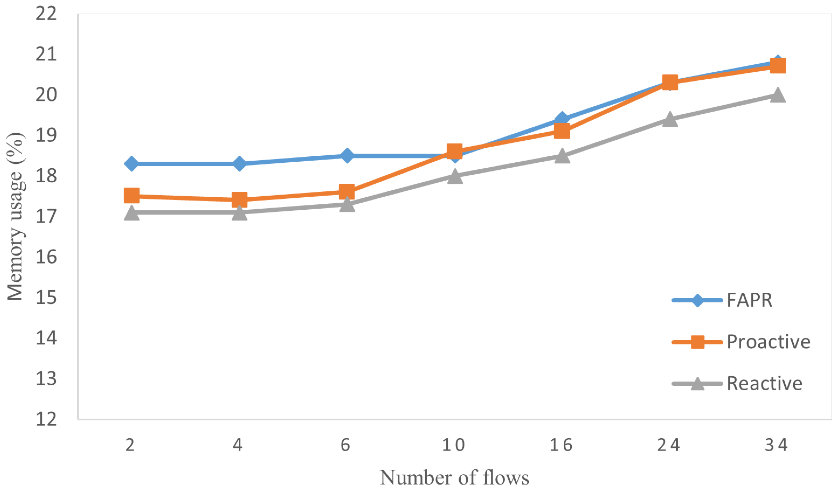
5.3.4. CPU and Memory Utilization

Figure 13 and Figure 14 show the CPU utilization and memory utilization of these three schemes, respectively. The CPU and memory utilization refer to the amount of CPU and memory resources consumed by the entire network simulation program when it is fully operational. When the system is not running the simulated network environment, the CPU utilization is about 4.5 % and the memory utilization is about 12 % . As seen from these two figures, there is only a slight increase in the CPU utilization and memory utilization of the three schemes as the number of flows increases. Benefiting from the resource management and scheduling mechanisms of the operating system, as well as the high performance of modern computer systems, fluctuations of CPU and memory utilization exist while within a very small range. In addition, it can be observed that there is no significant difference in CPU usage and memory usage among these three schemes. In conclusion, when compared with the other two schemes, the FAPR scheme does not cause additional hardware resource costs, which is applicable in practice.

6. Conclusions and Future Work

In response to the single link failure issue in the SDN data plane, this paper proposes the FAPR scheme, which combines the proactive and reactive schemes. Firstly, the proposed scheme uses the pro-VLAN method [19] to implement automatic path switching after link failures, and calculates multiple backup paths for the same link in advance. Secondly, when link failures happen, the controller assigns different backup paths to different types of flows through the analysis of flows, as well as the pre-calculated backup paths. As a result, FAPR not only achieves fast failure recovery and reduces the resource occupancy of the switches, but also promises the high availability and adaptability of backup paths to decrease the rate of flow congestion and interruption after the failure recovery process. Through simulation experiment verification and theoretical analysis, FAPR shows a high performance of failure recovery when compared with the traditional proactive and reactive schemes, which are detailed in the following three points.
(1)
FAPR keeps a stable and fast failure recovery speed no matter how the number of flows varies, reducing over 65 % compared with the reactive scheme.
(2)
FAPR corresponds to the minimum interruption rate, which is reduced by 20 % and 50 % compared with the reactive and proactive schemes, respectively.
(3)
FAPR only installs essential backup flow rules in switches in advance, and keeps the CPU and memory usages almost stable.
Although the FAPR scheme has unique advantages, there are unavoidable defects and unsolvable problems for future research. This scheme is not effective on every network topology. The bottleneck of the FAPR scheme is related most to many factors such as controller performance, frequency of single link failures, network scale, and the number of preset backup paths. Among them, controller performance is more important. The better the performance is, the higher is the number of limit conditions that can be supported. We can use performance-matched controllers and the multi-controller architecture in a real network environment, which will bring a greater economic burden. In addition, the judgment of flow types in this paper is realized through the transport layer protocols and port numbers, which cannot classify different flows in a fine-grained way. In the future, we intend to collect big data for different flows, and use machine learning algorithms for classification.

Author Contributions

Conceptualization, H.Q. and J.C.; methodology, H.Q.; software, H.Q.; validation, H.Q., J.C. and X.Q.; formal analysis, H.Q.; investigation, X.Z.; resources, M.C.; data curation, X.Z. and M.C.; writing—original draft preparation, H.Q.; writing—review and editing, H.Q. and J.C.; visualization, H.Q.; supervision, J.C.; project administration, H.Q. and J.C.; funding acquisition, X.Q. All authors have read and agreed to the published version of the manuscript.

Funding

This research was funded by the National Natural Science Foundation of China and The Research Project of Shanghai Science and Technology Commission (Grant No. 62102241, No. 23ZR142540).

Institutional Review Board Statement

Not applicable.

Informed Consent Statement

Not applicable.

Data Availability Statement

The raw data supporting the conclusions of this article will be made available by the authors on request.

Conflicts of Interest

The authors declare no conflicts of interest.

Appendix A

Table A1. Symbols of network model.
NotationDefinition
GNetwork topology
VThe switch set
EThe link set
e i j The link between switch i and switch j
f i j A flow on link e i j
F i j The set of f i j on link e i j
b i j A backup path for link e i j
B i j The set of b i j k for link e i j
b i j , f The backup path allocated for flow f i j
B i j , f The set of b i j , f on link e i j
b i j , f The result of processing b i j , f using backup path overlap removal algorithm
B i j , f The set of b i j , f on link e i j
o i j , f The original path of flow f i j
O i j , f The set of o i j , f on link e i j
p f A certain data packet of flow f

References

  1. McKeown, N.; Anderson, T.; Balakrishnan, H.; Parulkar, G.; Peterson, L.; Rexford, J.; Shenker, S.; Turner, J. OpenFlow: Enabling innovation in campus networks. SIGCOMM Comput. Commun. Rev. 2008, 38, 69–74. [Google Scholar] [CrossRef]
  2. Anerousis, N.; Chemouil, P.; Lazar, A.A.; Mihai, N.; Weinstein, S.B. The Origin and Evolution of Open Programmable Networks and SDN. IEEE Commun. Surv. Tutor. 2021, 23, 1956–1971. [Google Scholar] [CrossRef]
  3. Kazmi, S.H.A.; Qamar, F.; Hassan, R.; Nisar, K.; Chowdhry, B.S. Survey on Joint Paradigm of 5G and SDN Emerging Mobile Technologies: Architecture, Security, Challenges and Research Directions. Wirel. Pers. Commun. 2023, 130, 2753–2800. [Google Scholar] [CrossRef]
  4. Khorsandroo, S.; Sánchez, A.G.; Tosun, A.S.; Arco, J.; Doriguzzi-Corin, R. Hybrid SDN evolution: A comprehensive survey of the state-of-the-art. Comput. Netw. 2021, 192, 107981. [Google Scholar] [CrossRef]
  5. Raghavan, B.; Casado, M.; Koponen, T.; Ratnasamy, S.; Ghodsi, A.; Shenker, S. Software-defined internet architecture: Decoupling architecture from infrastructure. In Proceedings of the 11th ACM Workshop on Hot Topics in Networks, Redmond, WA, USA, 29–30 October 2012; pp. 43–48. [Google Scholar] [CrossRef]
  6. Khan, N.; Salleh, R.B.; Koubaa, A.; Khan, Z.; Khan, M.K.; Ali, I. Data plane failure and its recovery techniques in SDN: A systematic literature review. J. King Saud Univ.-Comput. Inf. Sci. 2023, 35, 176–201. [Google Scholar] [CrossRef]
  7. Keshari, S.K.; Kansal, V.; Kumar, S. A Systematic Review of Quality of Services (QoS) in Software Defined Networking (SDN). Wirel. Pers. Commun. 2021, 116, 2593–2614. [Google Scholar] [CrossRef]
  8. Sahoo, K.S.; Puthal, D.; Tiwary, M.; Rodrigues, J.J.; Sahoo, B.; Dash, R. An early detection of low rate DDoS attack to SDN based data center networks using information distance metrics. Future Gener. Comput. Syst. 2018, 89, 685–697. [Google Scholar] [CrossRef]
  9. Hu, T.; Yi, P.; Guo, Z.; Lan, J.; Zhang, J. Bidirectional Matching Strategy for Multi-Controller Deployment in Distributed Software Defined Networking. IEEE Access 2018, 6, 14946–14953. [Google Scholar] [CrossRef]
  10. Theodorou, T.; Mamatas, L. CORAL-SDN: A software-defined networking solution for the Internet of Things. In Proceedings of the 2017 IEEE Conference on Network Function Virtualization and Software Defined Networks (NFV-SDN), Berlin, Germany, 6–8 November 2017; pp. 1–2. [Google Scholar] [CrossRef]
  11. Adrichem, N.L.V.; Asten, B.J.V.; Kuipers, F.A. Fast Recovery in Software-Defined Networks. In Proceedings of the 2014 Third European Workshop on Software Defined Networks, Budapest, Hungary, 1–3 September 2014; pp. 61–66. [Google Scholar] [CrossRef]
  12. Muthumanikandan, V.; Valliyammai, C. A survey on link failures in software defined networks. In Proceedings of the 2015 Seventh International Conference on Advanced Computing (ICoAC), Chennai, India, 15–17 December 2015; pp. 1–5. [Google Scholar] [CrossRef]
  13. Rehman, A.U.; Aguiar, R.L.; Barraca, J.P. Fault-Tolerance in the Scope of Software-Defined Networking (sdn). IEEE Access 2019, 7, 124474–124490. [Google Scholar] [CrossRef]
  14. Grzimek, B.; Thoney, D.A.; Loiselle, P.V.; Schlager, N.; Hutchins, M. Grzimek’s Animal Life Encyclopedia, 2nd ed.; Thomson Gale: Detroit, MI, USA, 2003. [Google Scholar]
  15. Padma, V.; Yogesh, P. Proactive Failure Recovery in OpenFlow Based Software Defined Networks. In Proceedings of the 2015 3rd International Conference on Signal Processing, Communication and Networking (ICSCN), Chennai, India, 26–28 March 2015. [Google Scholar]
  16. Huang, H.; Guo, S.; Wu, J.; Li, J. Green DataPath for TCAM-Based Software-Defined Networks. IEEE Commun. Mag. 2016, 54, 194–201. [Google Scholar] [CrossRef]
  17. Li, H.; Li, Q.; Jiang, Y.; Zhang, T.; Wang, L. A declarative failure recovery system in software defined networks. In Proceedings of the 2016 IEEE International Conference on Communications (ICC), Kuala Lumpur, Malaysia, 22–27 May 2016; pp. 1–6. [Google Scholar] [CrossRef]
  18. Amarasinghe, H.; Jarray, A.; Karmouch, A. Fault-tolerant IaaS management for networked cloud infrastructure with SDN. In Proceedings of the 2017 IEEE International Conference on Communications (ICC), Paris, France, 21–25 May 2017; pp. 1–7. [Google Scholar] [CrossRef]
  19. Chen, J.; Chen, J.; Ling, J.; Zhou, J.; Zhang, W. Link Failure Recovery in SDN: High Efficiency, Strong Scalability and Wide Applicability. J. Circuit Syst. Comp. 2018, 27, 1850087. [Google Scholar] [CrossRef]
  20. Desai, M.; Nandagopal, T. Coping with link failures in centralized control plane architectures. In Proceedings of the 2010 Second International Conference on COMmunication Systems and NETworks (COMSNETS 2010), Bangalore, India, 5–9 January 2010; pp. 1–10. [Google Scholar] [CrossRef]
  21. Kempf, J.; Bellagamba, E.; Kern, A.; Jocha, D.; Takacs, A.; Skoldstrom, P. Scalable fault management for OpenFlow. In Proceedings of the 2012 IEEE International Conference on Communications (ICC), Ottawa, ON, Canada, 10–15 June 2012; pp. 6606–6610. [Google Scholar] [CrossRef]
  22. Ramos, R.M.; Martinello, M.; Esteve Rothenberg, C. SlickFlow: Resilient source routing in Data Center Networks unlocked by OpenFlow. In Proceedings of the 38th Annual IEEE Conference on Local Computer Networks, Sydney, NSW, Australia, 21–24 October 2013; pp. 606–613. [Google Scholar] [CrossRef]
  23. Ramos, R.M.; Martinello, M.; Rothenberg, C.E. Data Center Fault-Tolerant Routing and Forwarding: An Approach Based on Encoded Paths. In Proceedings of the 2013 Sixth Latin-American Symposium on Dependable Computing, Rio de Janeiro, Brazil, 1–5 April 2013; pp. 104–113. [Google Scholar] [CrossRef]
  24. Reitblatt, M.; Canini, M.; Guha, A.; Foster, N. FatTire: Declarative fault tolerance for software-defined networks. In Proceedings of the Second ACM SIGCOMM Workshop on Hot Topics in Software Defined Networking, Hong Kong, China, 16 August 2013; pp. 109–114. [Google Scholar] [CrossRef]
  25. Petroulakis, N.E.; Spanoudakis, G.; Askoxylakis, I.G. Fault Tolerance Using an SDN Pattern Framework. In Proceedings of the GLOBECOM 2017—2017 IEEE Global Communications Conference, Singapore, 4–8 December 2017; pp. 1–6. [Google Scholar] [CrossRef]
  26. Cascone, C.; Sanvito, D.; Pollini, L.; Capone, A.; Sansò, B. Fast failure detection and recovery in SDN with stateful data plane: Fast failure detection and recovery in SDN with stateful data planes. Int. J. Netw. Manag. 2017, 27, e1957. [Google Scholar] [CrossRef]
  27. Isyaku, B.; Bin Abu Bakar, K.; Nagmeldin, W.; Abdelmaboud, A.; Saeed, F.; Ghaleb, F.A. Reliable Failure Restoration with Bayesian Congestion Aware for Software Defined Networks. Comput. Syst. Sci. Eng. 2023, 46, 3729–3748. [Google Scholar] [CrossRef]
  28. Sharma, S.; Staessens, D.; Colle, D.; Pickavet, M.; Demeester, P. OpenFlow: Meeting carrier-grade recovery requirements. Comput. Commun. 2013, 36, 656–665. [Google Scholar] [CrossRef]
  29. Sharma, S.; Staessens, D.; Colle, D.; Pickavet, M.; Demeester, P. Fast failure recovery for in-band OpenFlow networks. In Proceedings of the 2013 9th International Conference on the Design of Reliable Communication Networks (DRCN), Budapest, Hungary, 4–7 March 2013; pp. 52–59. [Google Scholar]
  30. Borokhovich, M.; Schiff, L.; Schmid, S. Provable data plane connectivity with local fast failover: Introducing openflow graph algorithms. In Proceedings of the Third Workshop on Hot Topics in Software Defined Networking, Chicago, IL, USA, 22 August 2014; pp. 121–126. [Google Scholar] [CrossRef]
  31. Pfeiffenberger, T.; Du, J.L.; Arruda, P.B.; Anzaloni, A. Reliable and flexible communications for power systems: Fault-tolerant multicast with SDN/OpenFlow. In Proceedings of the 2015 7th International Conference on New Technologies, Mobility and Security (NTMS), Paris, France, 27–29 July 2015; pp. 1–6. [Google Scholar] [CrossRef]
  32. Thorat, P.; Raza, S.M.; Kim, D.S.; Choo, H. Rapid recovery from link failures in software-defined networks. J. Commun. Netw. 2017, 19, 648–665. [Google Scholar] [CrossRef]
  33. Kim, H.; Schlansker, M.; Santos, J.R.; Tourrilhes, J.; Turner, Y.; Feamster, N. CORONET: Fault tolerance for Software Defined Networks. In Proceedings of the 2012 20th IEEE International Conference on Network Protocols (ICNP), Austin, TX, USA, 30 October–2 November 2012; pp. 1–2. [Google Scholar] [CrossRef]
  34. Sharma, S.; Staessens, D.; Colle, D.; Pickavet, M.; Demeester, P. Enabling fast failure recovery in OpenFlow networks. In Proceedings of the 2011 8th International Workshop on the Design of Reliable Communication Networks (DRCN), Krakow, Poland, 10–12 October 2011; pp. 164–171. [Google Scholar] [CrossRef]
  35. Nguyen, K.; Minh, Q.T.; Yamada, S. A Software-Defined Networking Approach for Disaster-Resilient WANs. In Proceedings of the 2013 22nd International Conference on Computer Communication and Networks (ICCCN), Nassau, Bahamas, 30 July–2 August 2013; pp. 1–5. [Google Scholar] [CrossRef]
  36. Li, J.; Hyun, J.; Yoo, J.H.; Baik, S.; Hong, J.W.K. Scalable failover method for Data Center Networks using OpenFlow. In Proceedings of the 2014 IEEE Network Operations and Management Symposium (NOMS), Krakow, Poland, 5–9 May 2014; pp. 1–6. [Google Scholar] [CrossRef]
  37. Zhang, Y.; Beheshti, N.; Tatipamula, M. On Resilience of Split-Architecture Networks. In Proceedings of the 2011 IEEE Global Telecommunications Conference—GLOBECOM 2011, Houston, TX, USA, 5–9 December 2011; pp. 1–6. [Google Scholar] [CrossRef]
  38. Lee, K.; Kim, M.; Kim, H.; Chwa, H.S.; Lee, J.; Shin, I. Fault-Resilient Real-Time Communication Using Software-Defined Networking. In Proceedings of the 2019 IEEE Real-Time and Embedded Technology and Applications Symposium (RTAS), Montreal, QC, Canada, 16–18 April 2019; pp. 204–215. [Google Scholar] [CrossRef]
  39. Tajiki, M.M.; Shojafar, M.; Akbari, B.; Salsano, S.; Conti, M.; Singhal, M. Joint failure recovery, fault prevention, and energyefficient resource management for real-time SFC in fog-supported SDN. Comput. Netw. 2019, 162, 106850. [Google Scholar] [CrossRef]
  40. Liang, D.; Liu, Q.; Yan, B.; Hu, Y.; Zhao, B.; Hu, T. Low interruption ratio link fault recovery scheme for data plane in software-defined networks. Peer-to-Peer Netw. Appl. 2021, 14, 3806–3819. [Google Scholar] [CrossRef]
  41. Yuan, B.; Jin, H.; Zou, D.; Yang, L.T.; Yu, S. A Practical Byzantine-Based Approach for Faulty Switch Tolerance in Software-Defined Networks. IEEE Trans. Netw. Serv. Manag. 2018, 15, 825–839. [Google Scholar] [CrossRef]
  42. Song, S.; Park, H.; Choi, B.Y.; Choi, T.; Zhu, H. Control Path Management Framework for Enhancing Software-Defined Network (SDN) Reliability. IEEE Trans. Netw. Serv. Manag. 2017, 14, 302–316. [Google Scholar] [CrossRef]
  43. Bhatia, J.; Kakadia, P.; Bhavsar, M.; Tanwar, S. SDN-Enabled Network Coding-Based Secure Data Dissemination in VANET Environment. IEEE Internet Things 2020, 7, 6078–6087. [Google Scholar] [CrossRef]
  44. Narimani, Y.; Zeinali, E.; Mirzaei, A. QoS-aware resource allocation and fault tolerant operation in hybrid SDN using stochastic network calculus. Phys. Commun. 2022, 53, 101709. [Google Scholar] [CrossRef]
  45. Nunes, B.A.A.; Mendonca, M.; Nguyen, X.N.; Obraczka, K.; Turletti, T. A Survey of Software-Defined Networking: Past, Present, and Future of Programmable Networks. IEEE Commun. Surv. Tutor. 2014, 16, 1617–1634. [Google Scholar] [CrossRef]
  46. Eppstein, D. Finding the k Shortest Paths. Available online: https://ics.uci.edu/~eppstein/pubs/Epp-SJC-98.pdf (accessed on 7 January 2024).
Figure 1. An example of a proactive scheme.
Applsci 14 04719 g001
Figure 2. An example of a reactive scheme.
Applsci 14 04719 g002
Figure 3. An example of an FAPR scheme.
Applsci 14 04719 g003
Figure 4. FAPR overview.
Applsci 14 04719 g004
Figure 5. Standardized switch information.
Applsci 14 04719 g005
Figure 6. Standardized link information.
Applsci 14 04719 g006
Figure 7. 6-pod fat-tree topology.
Applsci 14 04719 g007
Figure 8. Recovery time using three schemes.
Applsci 14 04719 g008
Figure 9. Stability of recovery time using three schemes.
Applsci 14 04719 g009
Figure 10. Flow interruption rates using three schemes.
Applsci 14 04719 g010
Figure 11. Numbers of backup flow rules required for three schemes with bar graph.
Applsci 14 04719 g011
Figure 12. Numbers of backup flow rules required for three schemes with curve graph.
Applsci 14 04719 g012
Figure 13. CPU usage using the three schemes.
Applsci 14 04719 g013
Figure 14. Memory usage using the three schemes.
Applsci 14 04719 g014
Table 1. Chosen five tuples of a flow used in this paper.
ArgumentValueDescription
ipv4_srcIPv4 addressIPv4 source address
ipv4_dstIPv4 addressIPv4 destination address
transport_protoInterger 8bitTransport protocol
tcp/udp_srcInteger 16bitTCP/UDP source port
tcp/udp_dstInteger 16bitTCP/UDP destination port
Disclaimer/Publisher’s Note: The statements, opinions and data contained in all publications are solely those of the individual author(s) and contributor(s) and not of MDPI and/or the editor(s). MDPI and/or the editor(s) disclaim responsibility for any injury to people or property resulting from any ideas, methods, instructions or products referred to in the content.

