Article

Investigation of the Tensile Properties of High-Strength Bolted Joints in Static Drill Rooted Nodular Piles

1
School of Civil Engineering, Ningbo Tech University, Ningbo 315100, China
2
Research Center of Coastal and Urban Geotechnical Engineering of Zhejiang University, Hangzhou 310058, China
3
ZCONE High-Tech Pile Industry Holdings Co., Ltd., Ningbo 315101, China
*
Author to whom correspondence should be addressed.
Appl. Sci. 2024, 14(11), 4740; https://doi.org/10.3390/app14114740
Submission received: 23 April 2024 / Revised: 25 May 2024 / Accepted: 27 May 2024 / Published: 30 May 2024

Abstract

:
To address the persistence of traditional welded joints in the construction of static drill rooted nodular piles, high-strength bolted connections are introduced. Tensile performance tests were conducted on seven sets of full-scale joint specimens to evaluate the ultimate tensile bearing capacity, deformation ductility, and damage characteristics of high-strength bolted joints. Numerical models were established using ABAQUS 2020 software to complement the experimental findings. The results indicate that the ultimate tensile capacity test values of high-strength bolted joints and welded joints are comparable, both exceeding the values calculated by the pile ultimate tensile capacity specification formula. Moreover, the ultimate tensile capacity values of specimens with improved high-strength bolted joints surpass those of ordinary joints. Notably, in the final stages of testing, both high-strength bolted joints and welded joints experienced pull-off at the pier head of the prestressing reinforcement, with the joints remaining intact. The load-displacement curves obtained from the ABAQUS numerical model align closely with the experimental measurements. These findings offer valuable insights and serve as an experimental foundation for promoting the adoption and utilization of high-strength bolt joints.

1. Introduction

As construction technology continues to advance, precast concrete piles have become prevalent in the construction industry due to their wide application range, ease of quality control during pile formation, and convenient construction [1,2,3]. However, during the process of pile driving, conventional precast piles often generate a crowding effect on the surrounding soil, which can have significant implications for nearby structures [4,5,6,7]. Static drilling and rooting pre-tensioned prestressed concrete bamboo piles, known as PHDC piles, are an innovative environmentally friendly pile solution that utilizes hydraulic soil compaction around bamboo-reinforced pile bodies [8]. However, due to fabrication and transportation constraints, bamboo piles require joints for assembly. The load-bearing capacity of these piles is intricately linked to the performance of these joints.
Recent domestic and international research on the bearing capacity of pile connections has primarily focused on two main connection methods: welding and mechanical connections. Liu et al. [9] conducted bending tests on welded joints of prestressed concrete hollow square piles and concluded that the welded joints met the specification requirements in terms of test values. Additionally, they found that the quality of the weld joints significantly impacts the load-bearing capacity of the joints. Liu Weiyang et al. [10,11] conducted a comparative study on the durability of traditional welded joints and snap joints. Their research revealed that snap joints exhibit better performance under corrosion conditions compared to welded joints. Specifically, they observed that while snap joints maintain their strength relatively well in corrosive environments, the strength of welded joints decreases significantly due to corrosion. In some cases, the corrosion may lead to severe deterioration or even detachment of the welds. The literature highlights that while welded joints can meet the requirements for pile connection bearing capacity, they often exhibit poor durability performance, and the quality of welds may be inconsistent. Consequently, numerous domestic and international researchers have proposed various new types of connections to address these shortcomings.
Zhang et al. [12] introduced a snap-type quick coupling for endplate-enhanced prestressed concrete pipe piles without endplates. Their study demonstrated that this quick coupling offers rapid pile connection, is unaffected by human and weather factors, and possesses good corrosion resistance and durability. Gamble et al. [13] proposed a novel type of mechanical coupling joints and conducted tensile, flexural, and compression tests on them. The results confirmed the effectiveness of these coupling joints. Wu [14] introduced an embedded anchorage connection and conducted both full-scale tests and numerical simulations to assess its mechanical properties. The results of these tests and simulations confirmed that the joint specimens met the specified requirements, indicating the effectiveness and suitability of the embedded anchorage connection for its intended purpose. Xu et al. [15,16,17] designed a new type of connection joint for composite reinforced concrete precast square piles. Flexural performance tests on full-size specimens revealed that the ultimate flexural capacity of this joint exceeds the calculated value of the pile specification formula, indicating excellent load-carrying capacity and deformation performance. Wang et al. [18,19] conducted full-scale tests and numerical simulations on specimens of prestressed concrete square pile joints connected by elastic cards. Their findings confirmed that the bearing capacity meets design requirements and exhibited good deformation ductility.
Mechanical joints offer numerous advantages over welded joints, yet traditional welding remains the prevalent connection method in actual construction. Additionally, due to differing construction methods between static drill rooted nodular piles and ordinary prefabricated piles, especially regarding the inability of the pile body to provide counterforce during construction, certain rapid mechanical connections may not function properly. Therefore, this paper proposes the use of high-strength bolt joints for nodular pile connection. The study conducts full-scale tensile performance tests on the group of three traditional welded joints, the group of three high-strength bolt joints, and one of the improved high-strength bolt joints. Concurrently, numerical models were established using finite element software ABAQUS to research and compare high-strength bolt joints and traditional welded joints in terms of ultimate tensile bearing capacity, deformation ductility, and damage characteristics. Furthermore, the study compares the ultimate tensile load capacity of high-strength bolt joints with those of traditional welded joints. It also investigates the enhancement of tensile performance in improved bolt joints. These findings aim to provide a theoretical basis for the design and practical application of high-strength bolt joints.

2. Materials and Methods

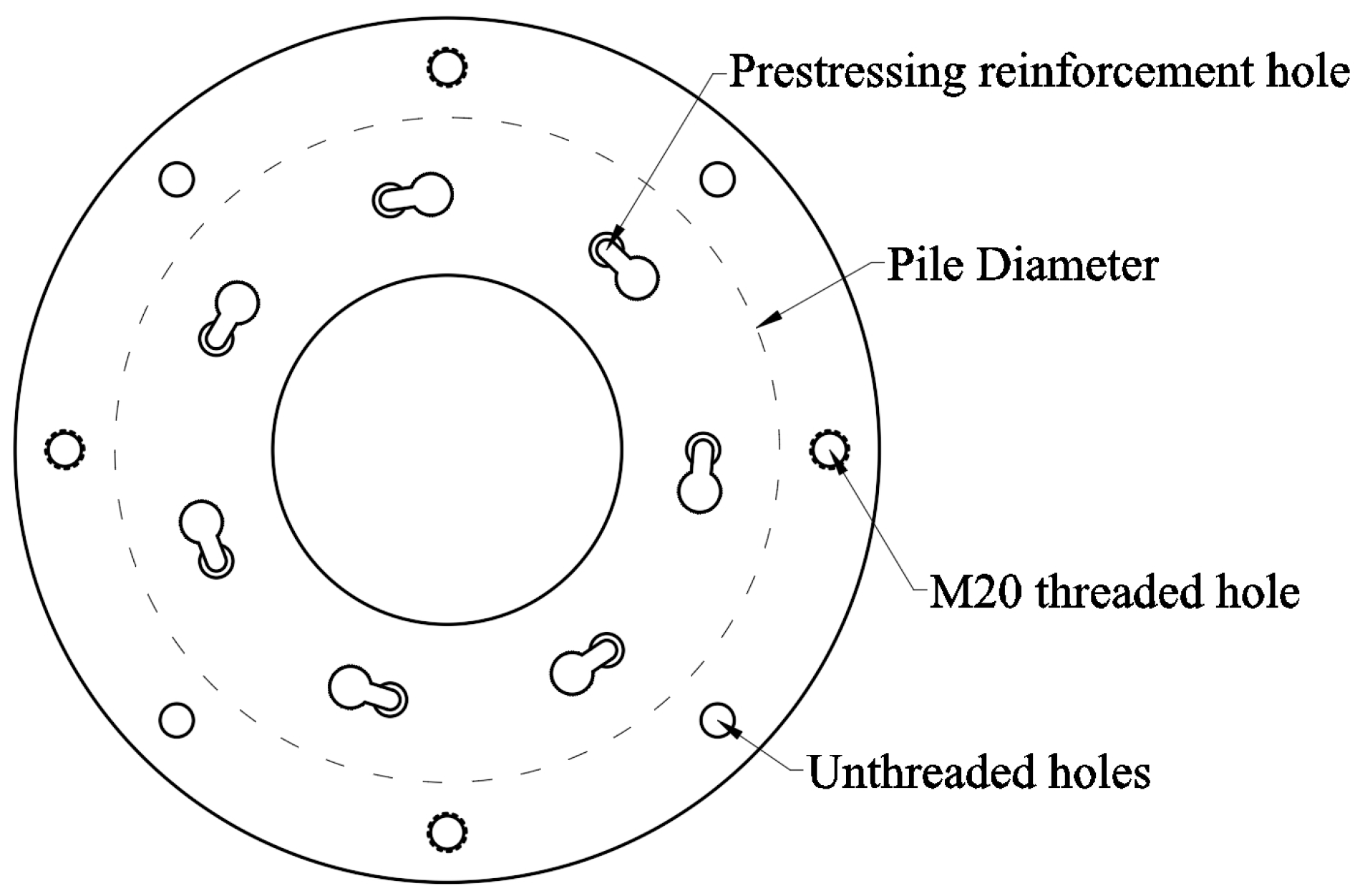
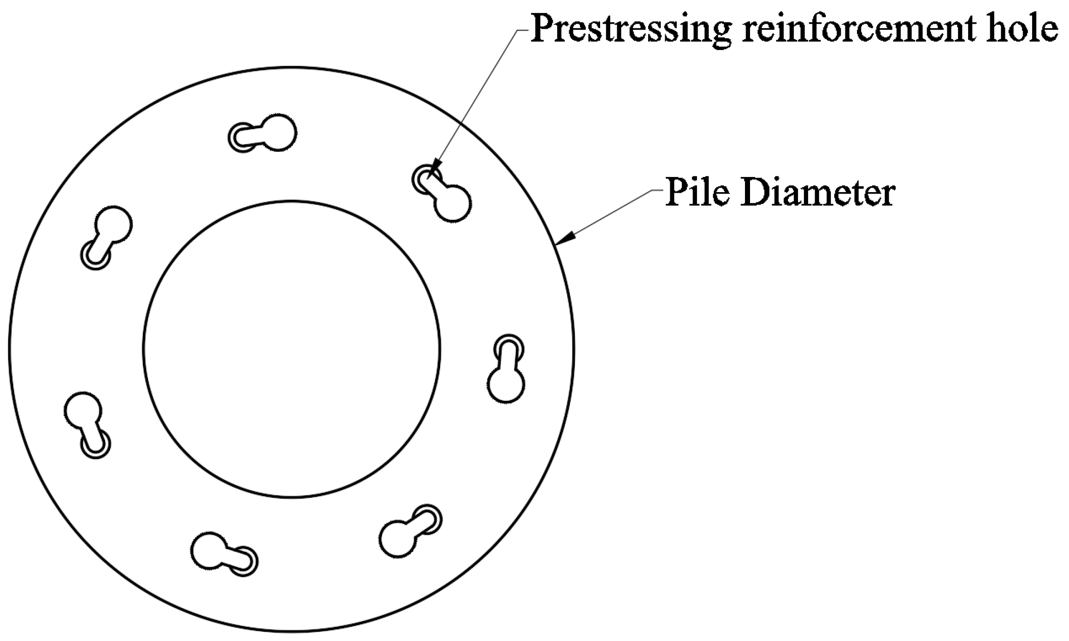
2.1. Specimen Design

The proposed new type of high-strength bolted joint for nodular piles takes into account the enlarged portion of the pile diameter at the pile body. When designing the end plate of the joint, the diameter of the end plate is enlarged beyond the diameter of the pile body. Additionally, the exceeding portion of the end plate features a staggered distribution of threaded holes, facilitating a quick high-strength bolted connection. This design ensures compatibility with the enlarged diameter of the nodular piles, enabling efficient and robust connections while maximizing the load-bearing capacity of the joint. The design dimensions for the joint end plate plane, as shown in Figure 1, are as follows: The end plate has a thickness of 20 mm, the diameter of the pile body is 400 mm, the diameter of the end plate is 520 mm, the diameter of bolt hole center is 460 mm. The number of bolt holes on the end plate varies according to the diameter of the nodular piles: 8 holes for 390 and 400 nodular piles, and 12 holes for 500 nodular piles. High-strength hexagonal head bolts with a performance level of 10.9 are used, with a bolt specification of M20 and a nominal length of 50 mm. These bolts are accompanied by high-strength washers for structural steel. In the joint tensile performance comparison test, seven groups of nodular piles connecting joints with a corresponding pile diameter of 400 mm were selected. Among them, three groups were high-strength bolted joints labeled LSJT-1, LSJT-2, and LSJT-3, three groups were traditional welded joints labeled HJJT-1, HJJT-2, and HJJT-3, and one group was an improved high-strength bolted joint labeled LSJT-4.
The geometry of each specimen, as illustrated in Table 1, includes the following parameters: D1 is the outer diameter of the end plate; D2 is the inner diameter of the end plate; Db is the diameter of the bolt hole position; and Dp is the diameter of the main bar position. The traditional welded joint end plate plane is depicted in Figure 2. The improved high-strength bolted joint end plate, on the other hand, positions the bolt holes closer to the pile body, enhancing the mechanical performance of the connection joint.

2.2. Material Properties

The connection end plates are constructed from Q235B steel, while the prestressing steel bars consist of spiral channel steel bars for low relaxation prestressed concrete. The bolts utilized are high-strength large hexagonal head bolts with a performance level of 10.9 s. In the case of welded joints, welding rods of type E43 (Covered electrodes for manual metal arc welding of non-alloy and fine grain steels, whose minimum tensile strength is 430 MPa) are employed for welding purposes. The above materials are in accordance with the relevant industry specifications [20,21,22], and their modulus of elasticity E and yield strength fy, ultimate strength fu were measured according to the corresponding material tests, as shown in Table 2.

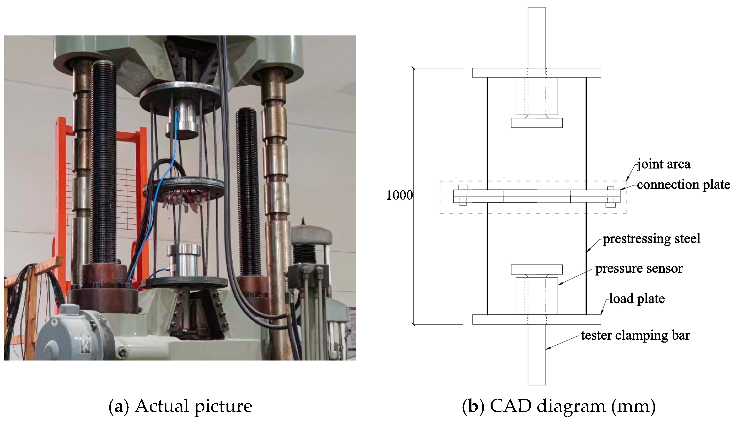
2.3. Loading Program

The specimens were loaded using the WAW-1000C computer-controlled electro-hydraulic servo universal testing machine (Ningbo, China), as depicted in Figure 3. During the experiments, an independent pressure sensor was employed to verify the accuracy of the tensile force applied by the testing machine. The loading process consists of two stages: pre-loading and formal loading. The pre-loading process includes three gradual levels: 50 kN, 100 kN, and 200 kN, each with a slow loading rate. Upon reaching each load level, the load is maintained for one minute before proceeding to the next level. After completing the loading, a slow unloading process is initiated. During the pre-loading process, it is essential to inspect the stability of the support base and ensure the proper functioning of the instruments and loading equipment. Once the pre-loading phase is completed, resetting the initial readings allows the formal loading to commence. During the formal loading phase, the process begins with force-controlled loading, divided into four stages, until the tension force reaches the designed tensile bearing capacity of the 400 mm diameter nodular pile. After each loading stage, the load is maintained for 2 min. Subsequently, the loading mode switches to displacement-controlled loading at a rate of 0.05 mm/s until either the prestressing steel bars fracture or the joint fails, at which point the loading is stopped.

2.4. Loading Program

The 3 mm × 2 mm type three-axis 45° strain rosettes are arranged on the surface of the connection end plate, as illustrated in Figure 4. The data acquisition device used is the DH3818Y static strain acquisition system (Ningbo, China). Seven strain rosettes are arranged on the surface of the bolted joint end plate. Among them, three are positioned 10 mm away from the edge of the prestressing steel bar hole, and four are positioned 10 mm away from the edge of the threaded hole. They are labeled as follows: 1# to 7#. Three strain rosettes are arranged on the surface of the welded joint end plate, positioned 10 mm away from the edge of the prestressing steel bar hole. They are labeled as 1# to 3#.

3. Results and Discussion

3.1. Test Phenomena

The testing loading process can be roughly divided into the following three stages: (1) During the initial stage of applying the load, the joint specimens are primarily in the elastic phase. The end plate and prestressing steel bars make sufficient contact, resulting in minimal deformation and linear growth of force with displacement. (2) As the loading force reaches a certain stage, some regions of the connection end plate begin to enter the tensile strengthening phase. Deformation of the end plate starts to increase, leading to a rapid growth in tensile displacement during this stage. Consequently, the degradation of stiffness becomes increasingly apparent. (3) When the loading reaches the bearing capacity calculated by theoretical formulas, displacement loading is applied. With the increase in displacement loading, most regions of the connection end plate begin to undergo plastic deformation. Simultaneously, the prestressing steel bars gradually enter the tensile strengthening phase until they reach their tensile strength and fracture, emitting a crisp snapping sound. At this point, the overall load-bearing capacity of the specimen suddenly drops, marking the end of the test. Throughout the process, neither the welded joints nor the bolted joints exhibited any failure due to joint separation. The decrease in the specimen’s load-bearing capacity was solely attributed to the fracture of the prestressing steel bar heads. The fracture of the steel bar heads is illustrated in Figure 5.

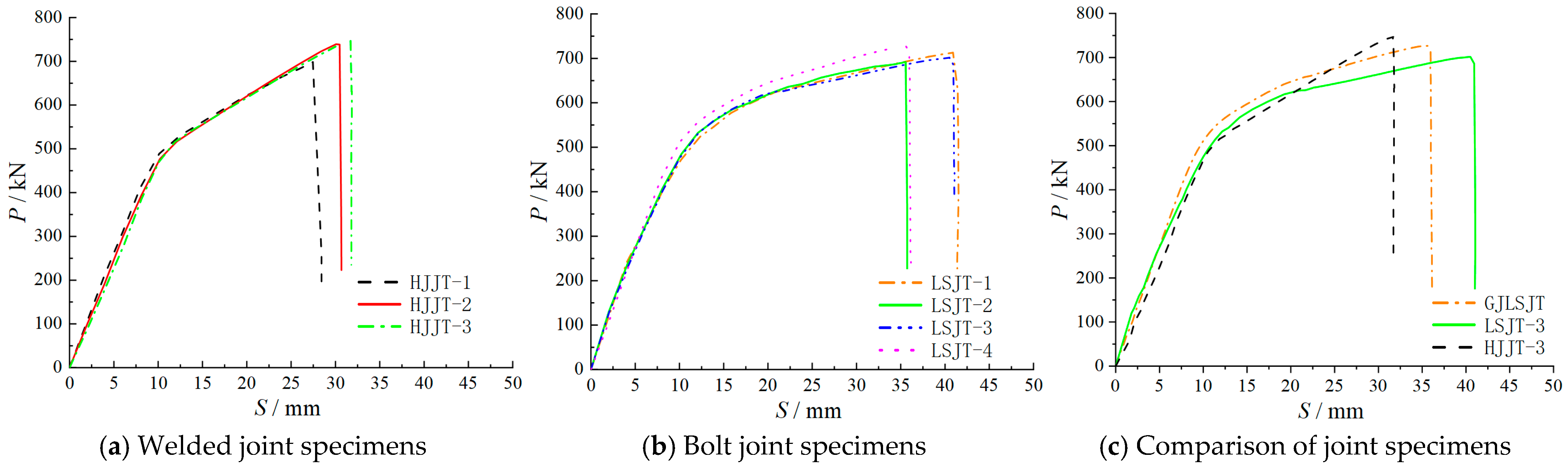
3.2. Tensile Strength

The tension load–displacement curves of each specimen, as shown in Figure 6, exhibit similar trajectories for specimens with the same type of connection joints. The specimens demonstrate low dispersion, remaining primarily in the elastic phase during the early stages of loading. Moreover, during this stage, as indicated in Figure 6c, it can be observed that even for specimens with different types of connection joints, their tensile stiffness is essentially similar. As the load increases, the specimens enter the yielding stage, and stiffness gradually decreases. For welded joint specimens, this stage begins at around 500 kN of load, similar to the trend observed in the improved bolted joint specimens. However, for normal bolted joint specimens, this stage is initiated at around 460 kN of load. When the stiffness decreases to a certain extent, it begins to stabilize until the steel bars of the specimen fracture. The variation in displacement at fracture among specimens with the same type of connection is attributed to the presence of different defects in the prestressing steel bars during the fabrication of the bar heads. Because the pre-stressing steel pier head is in the steel production is completed after the secondary processing production, so may be left in the pier head processing defects, and the pier head and easy to connect with the end plate uneven force, which is also easy to occur in the actual project where the problem. At the point of failure, the displacement of bolted joint specimens is consistently greater than that of welded joint specimens, indicating better ductility. However, the ultimate load capacity of bolted joint specimens is slightly lower than that of welded joint specimens. In comparison to normal bolted joint specimens, the curves of improved bolted joint specimens show little difference in the early stages of loading. However, after entering the yielding stage, the curves of improved bolted joint specimens surpass those of normal bolted joints.
Table 3 provides the experimental results (Nt) for the ultimate tensile bearing capacity of each joint specimen, as well as the design value (N) calculated according to the empirical formula specified in the regulations [23], the formula is shown in equation 1. The ultimate tensile bearing capacity of both types of joint specimens exceeds the design value for the pile’s axial tensile bearing capacity and is generally greater than 30% above it. Additionally, the ultimate tensile bearing capacity of the improved bolted joint specimens exceeds that of the normal bolted joint specimens. Furthermore, throughout the testing process, no failure occurred in the joint connections, indicating that the ultimate tensile bearing capacity of both types of joints meets the design requirements for pile connections.
N C f py A p
where: C represents the discount coefficient considering the influence of uneven force at the connection between the pier head and end plate of prestressing reinforcement, and 0.85 is taken here; fpy represents the design value of tensile strength of prestressing reinforcement, which is 1000 MPa; Ap represents the cross-sectional area of all longitudinal prestressing reinforcement.

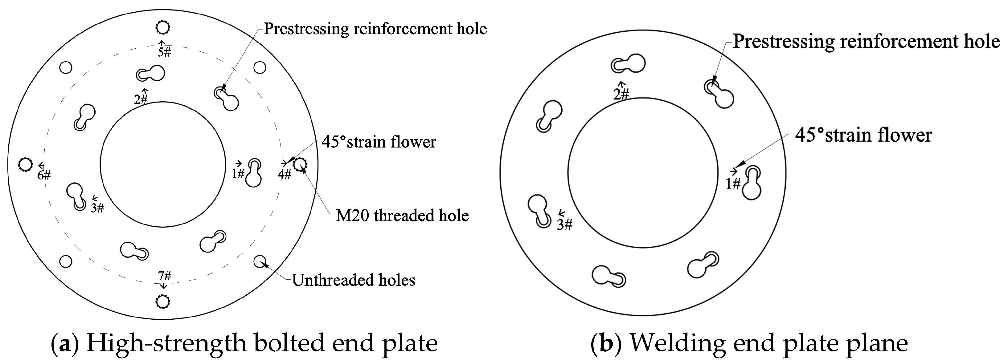
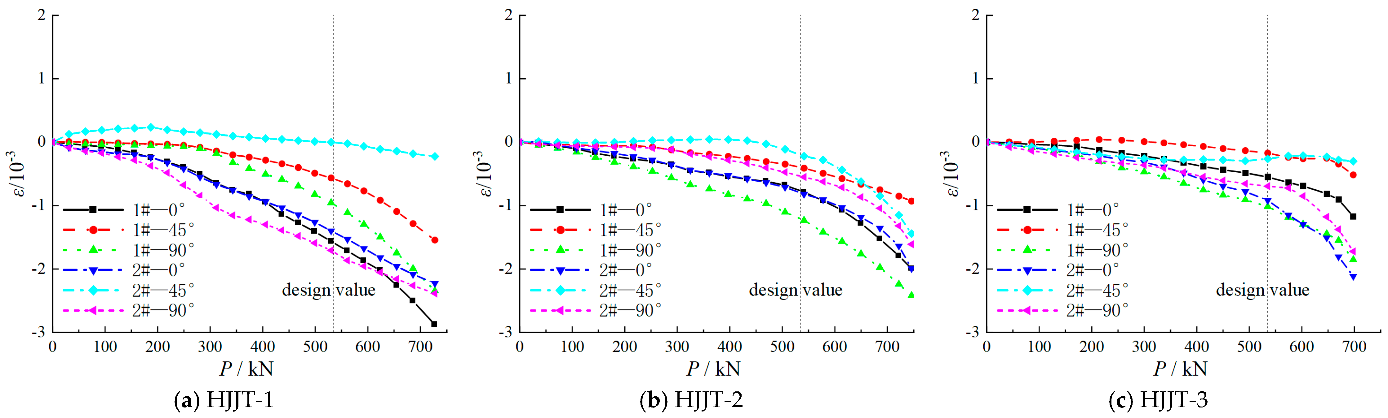
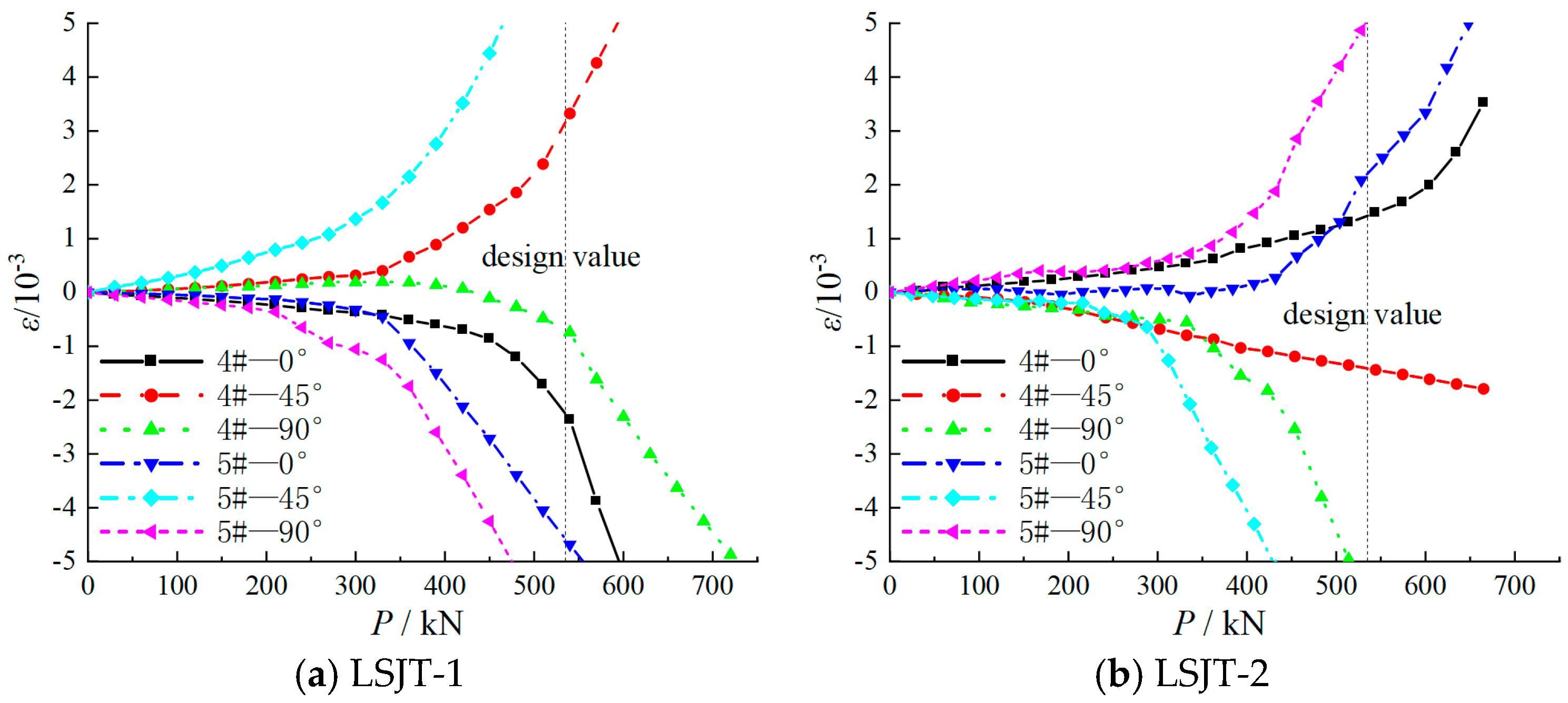
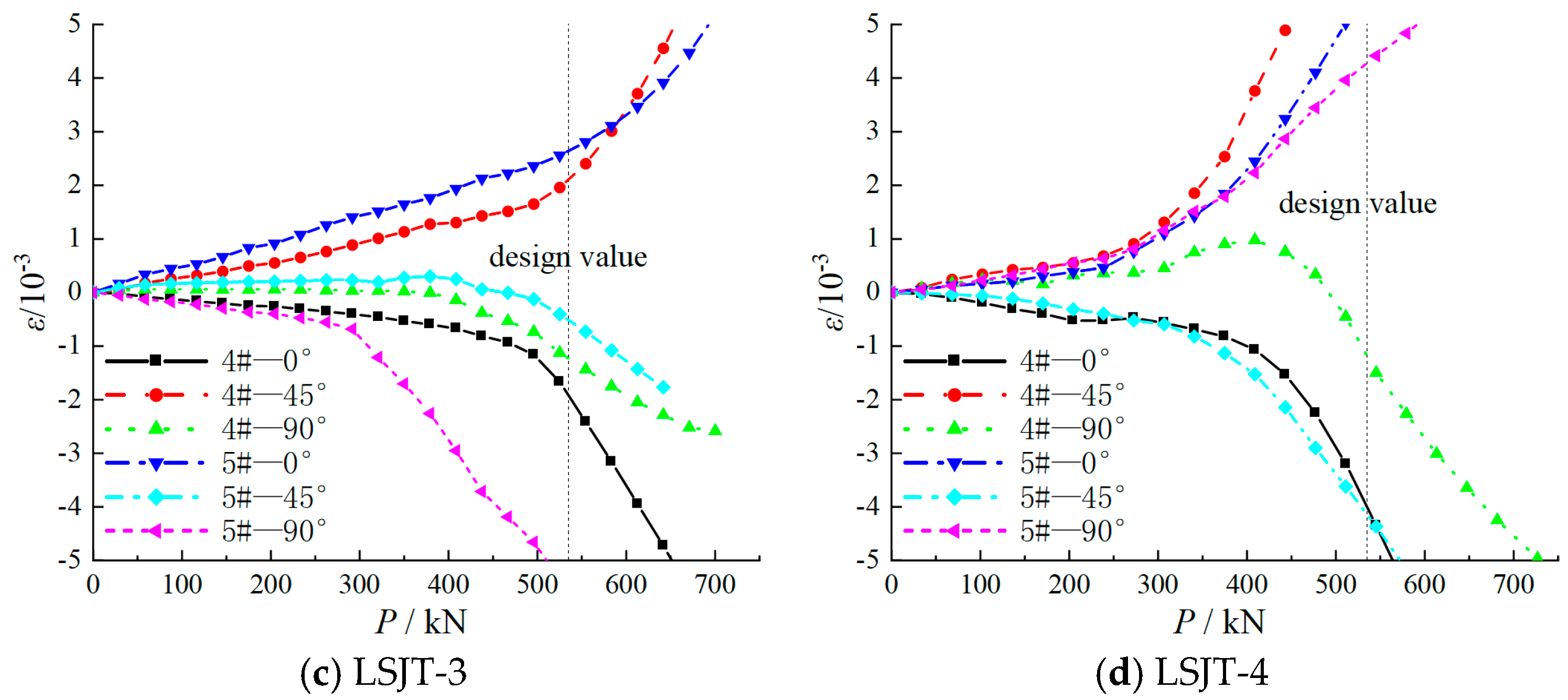
3.3. Strain Development

Figure 7, Figure 8 and Figure 9 depict the variation curves of strains at the locations of strain gauges near the steel bar holes on the end plates of welded joint specimens and bolted joint specimens, as well as the strains at the bolt holes on the end plates of bolted joint specimens, with the development of load. Comparing the strain development curves at the locations of steel bar holes on the end plates of both types of joint specimens reveals that the strains remain within the range of 0.002 throughout the loading process, indicating minimal strain values.
For the bolted joint specimens as a whole, the strain curves at the locations of the steel bar holes on the end plates are more concentrated compared to the strain curves at the bolt holes. Additionally, the extent of strain development at the locations of the steel bar holes on the end plates is significantly smaller than that at the bolt holes. This indicates that the bolt holes are the primary stress-bearing regions during the loading process. From the loading process perspective, during the early stages of loading, the strains at various measurement points on the specimens are relatively small, and the strains generally exhibit linear growth with increasing load. As the load increases, when the load reaches 290 kN, there is a rapid increase in strain at the bolt holes on the end plate, indicating that this part of the end plate has entered the plastic deformation stage. When the load reaches the design value of 535 kN for the pile’s axial tensile bearing capacity, strains at the steel bar holes also begin to experience rapid growth.

4. Finite Element Analysis

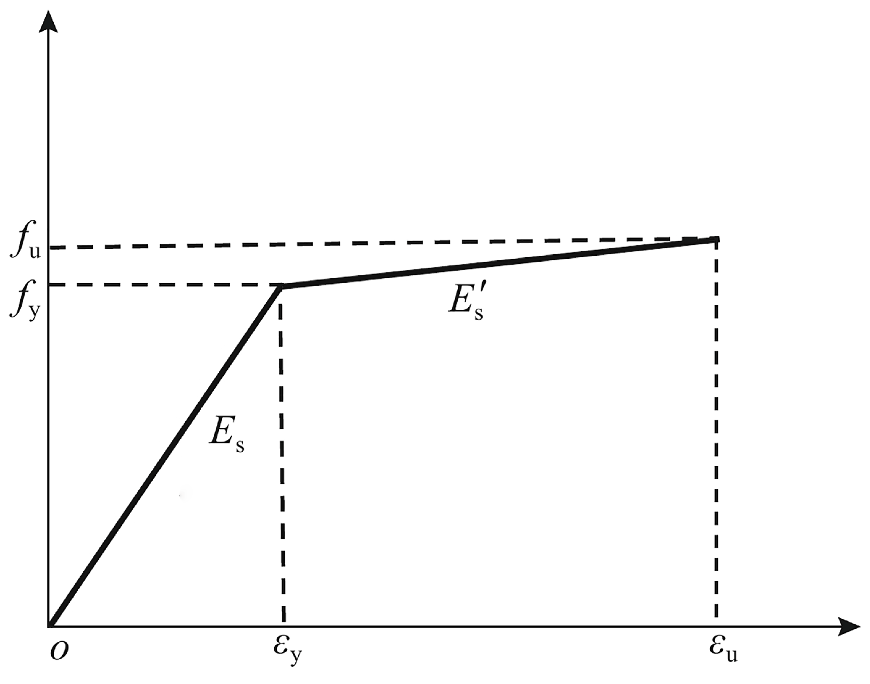
4.1. Constitutive Model for Materials

In the model, the materials of the prestressing steel bars, bolts, and end plates are all steel. A bilinear stress–strain model [24] is selected, and Figure 10 shows its stress–strain curve. The stress–strain relationship is as follows:
σ = E s ε ε ε y ƒ y + E s ε ε y ε y ε ε u
In the equation, Es represents the elastic modulus of the steel, E s is the modulus of the hardening section. In this paper, E s is taken as 0.01Es. fy and εy represent the yield strength and yield strain, respectively, while fu and εu in the figure, respectively, represent the ultimate strength and ultimate strain. The material parameters are listed in Table 2.

4.2. Finite Element Model

Finite element models of the high-strength bolted and welded joint specimens were created using the ABAQUS finite element analysis software. The geometric dimensions of the models are identical to the actual specimens, as shown in Figure 11. All specimens were simulated using three-dimensional solid elements (C3D8R). The prestressing steel bars were connected to the end plates through binding constraints applied to the pre-drilled holes in the end plates. High-strength bolts were connected to the end plates through binding constraints to simulate the connection between the two end plates. In the welded joint specimens, the two end plates were connected to each other through binding constraints applied to the weld beads. During the meshing process, refinement was applied to the regions around the bolt holes and prestressing steel bar holes to better capture the stress variations near these features.

4.3. Comparison and Analysis

Based on the aforementioned computational model, numerical simulations were conducted for both bolted and welded joint specimens. Load–displacement curves were obtained and compared with the curves obtained from experiments, as shown in Figure 12. Overall, the simulated curves for each joint specimen closely match the experimental curves, exhibiting consistent trends and deformation stages. When comparing the three stages of the loading process, it is found that:
(1)
During the initial stage of elastic deformation, both the simulated and experimental curves exhibit linear elastic behavior. However, the stiffness of the simulated curve is higher than that of the experimental curve. This difference arises because the numerical simulation assumes ideal material behavior.
(2)
As the load increases, the stiffness of the curves begins to decrease with displacement. A comparison between the experimental and simulated curves of welded joints reveals that the stiffness change in the simulation process is slower, indicating better ductility.
(3)
When the prestressing steel bars start to yield, the stiffness of the specimens further decreases, and displacement increases rapidly with the increasing load. During this stage, the simulated curves closely match the experimental curves, exhibiting almost identical stiffness development. These results indicate that the numerical simulation method employed can accurately predict the tensile behavior of both types of joint configurations.
Figure 12. Comparison of test and simulated load–displacement curves.
Applsci 14 04740 g012

5. Conclusions

(1)
The experimental values of ultimate tensile bearing capacity obtained from the bolted joint specimens are close to those obtained from the traditional welded joint specimens. Moreover, both values exceed the ultimate tensile bearing capacity of the pile shaft calculated using the empirical formula specified in the regulations. The ratio of these values to the calculated ultimate tensile bearing capacity of the pile shaft is greater than 1.29, meeting the requirements for the load-bearing capacity of the joint in pile connections. Thus, this type of high-strength bolted connection proves to be a reliable connection method.
(2)
The experimental value of ultimate tensile bearing capacity obtained from the improved bolted joint specimens exceeds that of the normal bolted joint specimens. By positioning the bolt holes of the end plate closer to the pile shaft in the improved bolted joint, the load-bearing capacity of the bolted joint can be enhanced.
(3)
Both bolted joints and welded joints experienced prestressing steel bar rupture at the head of the prestressed reinforcement during the final failure of the experiment, with no failure occurring in the joints themselves. This indicates that both connection methods have a certain degree of load-bearing capacity surplus.
(4)
The strains at the prestressing steel bar holes in the end plate of the joint specimens are relatively small and develop slowly, remaining essentially within the range of 0.002. Conversely, the strains at the bolt holes in the end plate are larger and develop rapidly, entering the yield phase earlier in the loading process.
(5)
The load–displacement curves obtained from the numerical models established using ABAQUS closely match the curves obtained from experiments, indicating that they can reasonably predict the entire process of joint tensile loading until failure.
It is worth noting that this study focused solely on the joints and did not consider the connection performance in the presence of the pile. Additionally, parameter analysis of the joints to optimize their connection performance was not conducted. These aspects could be explored in future research endeavors.

Author Contributions

Conceptualization, Q.D.; Methodology, Q.D., Z.W., R.Z. and X.X.; Validation, Z.W.; Writing—original draft, Q.D.; Writing—review and editing, Z.W., R.Z. and X.X.; Visualization, Q.D.; Supervision, Z.W. and X.X.; Project administration, Z.W. and R.Z. All authors have read and agreed to the published version of the manuscript.

Funding

This research was funded by the Ningbo Major Special Projects (No.2022Z030) and Ningbo Youth Science and Technology Innovation Leading Talent Project (No.2023QL018).

Institutional Review Board Statement

Not applicable.

Informed Consent Statement

Not applicable.

Data Availability Statement

The raw data supporting the conclusions of this article will be made available by the authors on request.

Conflicts of Interest

Author Rihong Zhang was employed by the company ZCONE High-Tech Pile Industry Holdings Co., Ltd. The remaining authors declare that the research was conducted in the absence of any commercial or financial relationships that could be construed as a potential conflict of interest.

References

  1. Zhang, Z. Piling Engineering; China Building Material Industry Press: Beijing, China, 2007; pp. 1–23. [Google Scholar]
  2. Wu, J.; Geng, S.; Liang, Y.; Wang, K.; Ying, X. Analytical study on soil squeezing effect during pile construction with enlarged spudcan. J. Zhejiang Univ.-Eng. Sci. 2024, 58, 130–139. [Google Scholar]
  3. Wang, K.; Xie, K.; Zeng, G. An analytical solution to force vibration of foundation pile under exciting force and its application. China Civ. Eng. J. 1998, 31, 56–67. [Google Scholar]
  4. Luo, Z.; Gong, X.; Wang, J.; Wang, W. Numerical simulation and factor analysis of jacked pile compacting effects. J. Zhejiang Univ.-Eng. Sci. 2005, 7, 992–996. [Google Scholar] [CrossRef]
  5. Zhou, J.; Wang, K.; Gong, X.; Zhang, R. Numerical simulation on behavior of static drill rooted pile under tension. J. Zhejiang Univ.-Eng. Sci. 2015, 49, 2135–2141. [Google Scholar]
  6. Wang, Z.; Zhang, R.; Wang, K.; Fang, P.; Xie, X.; Xu, H.; Li, J. Bearing characteristic of static drill rooted pile considering condition of energy carrier. J. Zhejiang Univ.-Eng. Sci. 2019, 53, 11–18, 50. [Google Scholar]
  7. Zhou, J.; Gong, X.; Wang, K.; Zhang, R. Model test on load transfer mechanism of a static drill rooted nodular pile. J. Zhejiang Univ.-Eng. Sci. 2015, 49, 531–537, 546. [Google Scholar]
  8. G37; Static Drill Rooted Nodular Piles with Pre-Tensioned Prestressed Concrete. Zhejiang Standard: Zhejiang, China, 2018.
  9. Liu, F.; Jia, L.; Li, C. The test study on welding joint flexural bearing capacity of prestressed concrete hollow square pile. J. Wuhan Univ. Technol. 2008, 5, 105–108. [Google Scholar]
  10. Liu, W. Study on Long-Term Durability of Prestressed Concrete Square Pile Connection Joints with Resilient Clamping. Master’s Thesis, Zhejiang University, Hangzhou, China, 2021. [Google Scholar]
  11. Liu, W.; Gong, S.; Xu, Q.; Chen, G.; Liu, C.; Fan, H. Study on flexural performance of prestressed concrete square pile with resilient clamping connection joint after electricity accelerates corrosion. China Concr. Cem. Prod. 2021, 5, 33–38. [Google Scholar] [CrossRef]
  12. Zhang, F.; Niu, Z.; Li, L.; Xiong, H.; Zhou, Z. Quick coupling technology for endless plate reinforced prestressed concrete pipe pile. China Concr. Cem. Prod. 2012, 5, 38–41. [Google Scholar]
  13. Gamble, W.L.; Bruce, R.N. Tests of 24 inch square prestressed piles spliced with abb splice units. Pci J. 1990, 35, 56–73. [Google Scholar] [CrossRef]
  14. Wu, Z. Effective Post-Tensioned Splicing System for Prestressed Concrete. Ph.D. Thesis, University of South Florida, Tampa, FL, USA, 2016. [Google Scholar]
  15. Xu, Q.; Chen, G.; He, J.; Gong, S.; Xiao, Z. Flexural performance experiment of connection joint for composite reinforcement concrete prefabricated square piles. J. Zhejiang Univ.-Eng. Sci. 2017, 51, 1300–1308. [Google Scholar] [CrossRef]
  16. Xu, Q.; Chen, G.; He, J.; Gong, S. Flexural performance experiment of composite reinforcement concrete prefabricated square piles. J. Zhejiang Univ.-Eng. Sci. 2016, 50, 1768–1776. [Google Scholar] [CrossRef]
  17. Xu, Q.; Yang, F.; Cheng, G.; Gong, S.; Xiao, Z. Finite element analysis of flexural performance of composite reinforced concrete prefabricated square piles. J. Build. Struct. 2018, 39 (Suppl. 1), 297–305. [Google Scholar] [CrossRef]
  18. Wang, Y.; Chen, G.; Xu, Q.; Gong, S.; Xiao, Z.; Fan, H. Study on Tensile Behavior of Prestressed Concrete Square Pile Connection Joint with Resilient Clamping. J. Disaster Prev. Mitig. Eng. 2018, 38, 1003–1011. [Google Scholar] [CrossRef]
  19. Zhou, J.; Wang, Y.; Gong, S.; Zhang, A.; Liu, C.; Fan, H. Study on flexural behavior of prestressed concrete square pile connection joint with resilient clamping. Build. Struct. 2020, 50, 121–127, 133. [Google Scholar] [CrossRef]
  20. GB/T 1228; High Strength Large Hexagon Head Bolts for Steel Structures. Standards Press of China: Beijing, China, 2006.
  21. GB/T 700; Carbon Structural Steel. Standards Press of China: Beijing, China, 2006.
  22. GB/T 5223.3; Steel Bars Prestressed Concrete. Standards Press of China: Beijing, China, 2005.
  23. GB 550010; Code for Design of Concrete Structures. Standards Press of China: Beijing, China, 2010.
  24. Tang, M.; Ling, Z.; Qi, Y. Bending strength of connection joints of prestressed reinforced concrete pipe piles. Buildings 2023, 13, 119. [Google Scholar] [CrossRef]
Figure 1. High-strength bolted end plate plane.
Applsci 14 04740 g001
Figure 2. Welding end plate plane.
Applsci 14 04740 g002
Figure 3. Tensile test loading of joint specimens.
Applsci 14 04740 g003
Figure 4. Strain relief position on end plate surface.
Applsci 14 04740 g004
Figure 5. Prestressing steel pier head pull-off.
Applsci 14 04740 g005
Figure 6. Load–displacement curve of test specimen.
Applsci 14 04740 g006
Figure 7. Strain development near holes in prestressing steel bars with welded joints.
Applsci 14 04740 g007
Figure 8. Strain development near holes in prestressing steel bars with bolted joints.
Applsci 14 04740 g008
Figure 9. Strain development near bolt holes in bolted joints.
Applsci 14 04740 g009aApplsci 14 04740 g009b
Figure 10. Bilinear stress–strain curve model.
Applsci 14 04740 g010
Figure 11. Specimen finite element model.
Applsci 14 04740 g011
Table 1. Geometry of end plates.
Joint Specimen NumberD1/mmD2/mmDb/mmDp/mm
LSJT-1520210460154
LSJT-2520210460154
LSJT-3520210460154
LSJT-4490210430154
HJJT-1400210-154
HJJT-2400210-154
HJJT-3400210-154
Table 2. Specimen material strength parameters.
MaterialE/GPafy/MPafu/MPa
High-strength bolt2069001000
end plate210235451
prestressing steel20214241520
welding rod206330430
Table 3. Comparison of test results of tensile ultimate bearing capacity with calculated values from code equations.
Joint Specimen NumberNt/kNN/kNNt/N
LSJT-17125351.33
LSJT-26915351.29
LSJT-37015351.31
LSJT-47265351.36
HJJT-16985351.30
HJJT-27395351.38
HJJT-37465351.39
Disclaimer/Publisher’s Note: The statements, opinions and data contained in all publications are solely those of the individual author(s) and contributor(s) and not of MDPI and/or the editor(s). MDPI and/or the editor(s) disclaim responsibility for any injury to people or property resulting from any ideas, methods, instructions or products referred to in the content.

