Article

Design and Control of a Shape Memory Alloy-Based Idle Air Control Actuator for a Mid-Size Passenger Vehicle Application

by
Pacifique Turabimana
1,
Jung Woo Sohn
2,* and
Seung-Bok Choi
3,4,*
1
Department of Aeronautics, Mechanical and Electronic Convergence Engineering, Graduate School, Kumoh National Institute of Technology, Daehak-Ro 61, Gumi 39177, Republic of Korea
2
School of Mechanical System Engineering, Kumoh National Institute of Technology, Daehak-Ro 61, Gumi 39177, Republic of Korea
3
Department of Mechanical Engineering, The State University of New York, Korea (SUNY Korea), 119 Songdo Moonhwa-Ro, Yeonsu-Gu, Incheon 21985, Republic of Korea
4
Department of Mechanical Engineering, Industrial University of Ho Chi Minh City (IUH), 12 Nguyen Van Bao Street, Go Vap District, Ho Chi Minh City 70000, Vietnam
*
Authors to whom correspondence should be addressed.
Appl. Sci. 2024, 14(11), 4784; https://doi.org/10.3390/app14114784
Submission received: 7 May 2024 / Revised: 24 May 2024 / Accepted: 28 May 2024 / Published: 31 May 2024

Abstract

:
The idle air control actuator is an important device in automotive engine management systems to reduce fuel consumption by controlling the engine’s idling operation. This research proposes an innovative idle air control (IAC) actuator for vehicle applications utilizing shape memory alloy (SMA) technology. The proposed actuator leverages the unique properties of SMAs, such as the ability to undergo large deformations upon thermal activation, to achieve precise and rapid controls in the air intake of automotive engines during idle conditions. The actuator structure mechanism consists of an SMA spring and an antagonistic spring made from steel. The design process utilizes both numerical and analytical approaches. The SMA spring is electrically supplied to activate the opening process of the actuator, and its closing state does not need electricity. However, the PID controller is used to control the applied current, which reduces the time taken by the actuator to achieve the actuation strokes. It shows good operability within multiple numbers of operation cycles. Additionally, the performance of the designed actuator is evaluated through mathematical algorithms by integrating it into the engine’s air intake system during idle operating conditions. The results demonstrate the effectiveness of the SMA-based actuator in achieving rapid control of the air intake through bypass, thereby improving engine idle conditions.

1. Introduction

Internal combustion engines (ICEs) have been the dominant power source for automotive applications over the centuries. A relentless pursuit of efficiency and performance has marked the evolution of ICEs over the years [1]. One critical component in optimizing the performance of an internal combustion engine is the idle air control device/actuator, which controls the engine’s air inlet and maintains optimal combustion characteristics during idle conditions. A well-performed idle air control actuator contributes to smoother idling and plays a significant role in fuel economy, emission reduction, and overall engine idling performance. Nowadays, researchers are interested in developing automotive engine actuators using quick response, weightless, and controlled materials like shape memory alloy (SMA) materials to offer a potential solution to the challenges associated with mechanical or traditional actuators. Traditional idle air control valves utilize electromagnetic actuators or stepper motors. They have served their purpose well but face limitations of response time, complexity, and electric energy consumption.
Shape memory alloys (SMAs) are unique smart materials that can regain their original shape when subjected to a specific thermal stimulus, such as heat [2,3]. This property has been harnessed in various engineering applications, from biomedical to aerospace actuators. SMAs are classified into different categories based on the alloying types but the most widely known and used is Nickel Titanium (NiTi) Shape Memory Alloy, known as Nitinol. Its shape memory effect (SME) and superelasticity make it suitable for various applications, including in the automotive sector. NiTi shape memory alloys are available on the market in different forms including cold-rolled strips and tubes [4,5,6], wires [7,8], sheets or plates [9,10], foils [11,12], and springs [10,13,14]. In different complicated actuators that use composite materials, shape memory alloy wires are embedded in the composite to improve their working ability, such as fast response in shape-changing of the structure, mechanical behaviour, and impactful actuation [15,16]. They are used in automotive applications but many are also widely applied in robotic systems [17,18]. The shape memory alloys in the tube form operate at higher temperatures than their wired counterparts [19]. The hollow form of the tube provides the cooling channel of these shape memory alloy-based actuators [19,20]. The cooling time of SMA is reduced and the life span of the actuators increases. Plate-based shape memory alloys are used in aerospace actuators for the vibration and stiffness control of flexible structures [21]. In the automotive industry, they are applied in adaptive shock control actuators [22,23]. The actuators with improved stroke and fast actuation responses use spring-based shape memory alloys [13,24]. SMA spring actuators are mostly applied in the automotive sector. They perform at the constant strain within many actuation cycles and can be deformed up to 200% of their length with low mechanical loads [25,26]. Moreover, the coil spring increases the amount of restoring energy to reduce the consumed energy during actuator operation. An actuator can have two SMA springs or a wire and spring combination, but one element serves as a biasing material [27].
Several researchers are interested in working on SMAs for automotive applications to modernise actuators in this sector. They are used to simulate or experiment to find the results of a proposed designed actuator. None have been used to evaluate their operability in the complete system, which represents the innovation of this work. Song et al. [28] used a shape memory alloy with a Nitinol type to design and control a variable exhaust nozzle actuator. The configuration has SMA wire and a bias spring, but the area is reduced by 40% from the existing mechanical one. Fawcett et al. [29] proposed an emergency brake using an SMA material in its operation. They performed only an experimentation approach during the design. The brake generates high torque and does not require electricity in off-mode conditions. Sathish et al. [30] introduced the two-way SMA spring applied in passenger vehicle suspension to replace the traditional one by improving vehicle comfort and performance. Their experiment results show a significant reduction in the sprung mass displacement from various excitation frequencies. Nissele et al. [31] designed and manufactured an SMA-based active aerodynamic for automotive applications. The surface is smooth and self-controlled with a good arrangement compared to the traditional ones. Pedro et al. [32] performed both theoretical simulations and experiments for designing an SMA wire-based mechanism for aeronautical applications. They investigated the generated torque used for flap actuation. Venkata et al. [33] conducted a research study to morph automotive fender skirts that use composite material embedded with SMA wires. The design process includes mathematical modelling and experiments. The findings describe the reduction in the actuation time of 95 % with a 62 % weight reduction compared to the dome-shaped steel fender skirt. Pacifique et al. [13] proposed an active thermostat that uses an SMA spring to activate its operations. The design covers mathematical modelling and simulation, which show an engine overheating reduction and low-pressure fluctuation in the cooling system. Tiegang et al. [34] proposed a novel non-embedded, adjustable, and flexible SMA actuator to be applied in the exhaust nozzle to vary its area. The study includes both theoretical and experimental approaches.
This research aims to design the SMA-based Idle Air Control (IAC) actuator for vehicle application. The IAC actuator closes or opens the air path through the bypass for engine idling conditions from its pintle’s stroke. The design process includes numerical analysis with COMSOL Multiphysics software and analytical methods with mathematical modelling and simulation using MATLAB software (R2023b). The SMA spring activates the actuator from its phase transformations using electric current. A PID controller and limiters are used for the output responses to reduce the time taken for thermal stimuli. The actuator’s operations are evaluated based on the practical spark ignition engine idle-condition input parameters using MATLAB Simulink software (R2023b). The model is simple and weightless, with the rapid opening of the idle air path at a low consumed electric current of only 2 A.

2. Materials and Methods

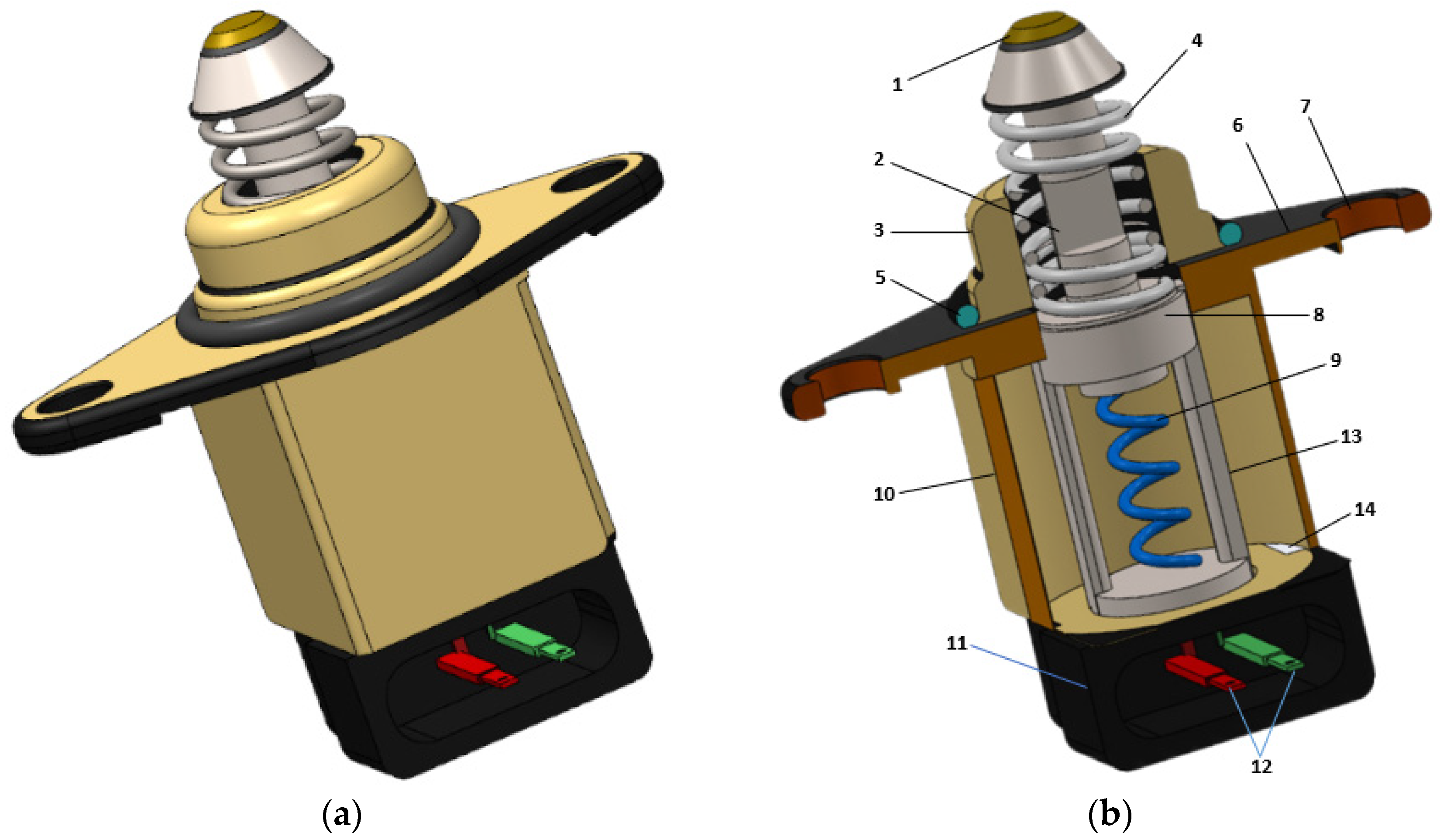
2.1. Structural Configuration of Proposed IAC Actuator

The structure of the idle air control (IAC) actuator identifies the external physical appearance and internal parts arrangement with their shapes. Figure 1a shows a completely assembled actuator. It has three main parts with different shapes and colours. The bottom part is in rubber colour and the middle part with chromate colour are fixed parts to hold the internal components. The remaining one is a part of the IAC actuator to be fixed into the throttle body. Figure 1b shows the 14 components of a shape memory alloy-based idle air control actuator. Each one has its role in the operation of the actuator. The pintle and rod are the moving components based on the state of the actuator. The stability of the rod holder comes from the vertical support, which assembles it with the outer housing and the fixture plate.
The fixture plate supports the actuator onto the throttle body through the bolt holder and bolts with nuts. O ring protects the actuator from leakage of air in the bypass. Electric connectors in the connecting box relate to the electric wires from the engine electronic control module and supply the electric current to the SMA spring. This spring is made from a Nickel-and-Titanium (NiTi) alloy with 52% of Ni and 48% of Ti. The reference specifications of the SMA spring are from the released datasheet of Nexmetal Corporation, Sheridan, WY, USA, for the NiTi SMA coil spring [35]. The rod holder, bias spring, and rod are made from stainless steel. The fixture plate and vertical support are made of low-carbon steel. Inner and outer housings are made from grey cast iron. Together with the cooling slot, they facilitate a high rate of heat transferred to the ambient from the SMA spring during cooling time. The connecting box is made of ductile cast iron. Using cast iron in these components increases their ability to work outside with different temperatures and vibrations from the engine. Apart from the simple structure of the actuator, it has a low weight of 17.46 g. However, two springs (SMA spring and Bias spring) shown in Figure 2 are the main components to manage this IAC actuator’s operation.
The bias spring, shown in Figure 2a, is designed to work under compression. Its parameters are indicated by a subscript b ( . b ). Figure 2b illustrates an SMA spring. It is designed to work under mechanical extension. Its parameters have a subscript s ( . s ) to differentiate them from those of a bias spring. The wire diameter ( d b ) was selected from the stainless steel wire available on the market. It is the basic element used to calculate other spring parameters as expressed in Equation (1). It is an equation of modelling modified from a study conducted by Turabimana et al. [13]. The parameters of the SMA spring were identified based on force ( F b ) that should extend to the full displacement of the SMA spring at its martensite phase.
F b = 8 D b 0 τ m π d b 3 C f
where F b is a mechanical driving force to extend the SMA alloy spring, C f is a shear stress correction factor of the spring and it is calculated based on the spring index ( i s ) in Table 1. τ m is a maximum shear stress of the spring, which defines the spring’s working ability [36]. This stress for coil spring from stainless steel is 515 MPa. The two springs are designed using the same theory of coil spring, but the working conditions and parametric relationship are different. The parameters of an SMA spring stand to resist F b and can generate the force that compresses the bias spring during the austenite phase. The parameters of both springs are listed in Table 1.

2.2. Actuation Mechanism of SMA-Based IAC Actuator

2.2.1. Actuation Requirements of Proposed Actuator

The actuation mechanism of the proposed SMA-based IAC actuator starts with setting the operational requirements. Those requirements are constraints and specifications related to the environmental and working conditions of the actuator to achieve its final purpose. The constraints are within the bounds of the characteristics of the SMA spring listed in Table 2. The specifications are settled based on the existing idle air control valves of the internal combustion engine. The SMA spring is the operational active component of the actuator and activates its operating states. The specifications include power that allows for heating the SMA spring in a reasonable time, actuation time that defines the heating and cooling cycles, working stroke and temperature to the full opening of the actuator, and repeatability to confirm many possible operating numbers of cycles. Each specification or constraint has its function in the actuator’s operation to keep its life span long with good operability.

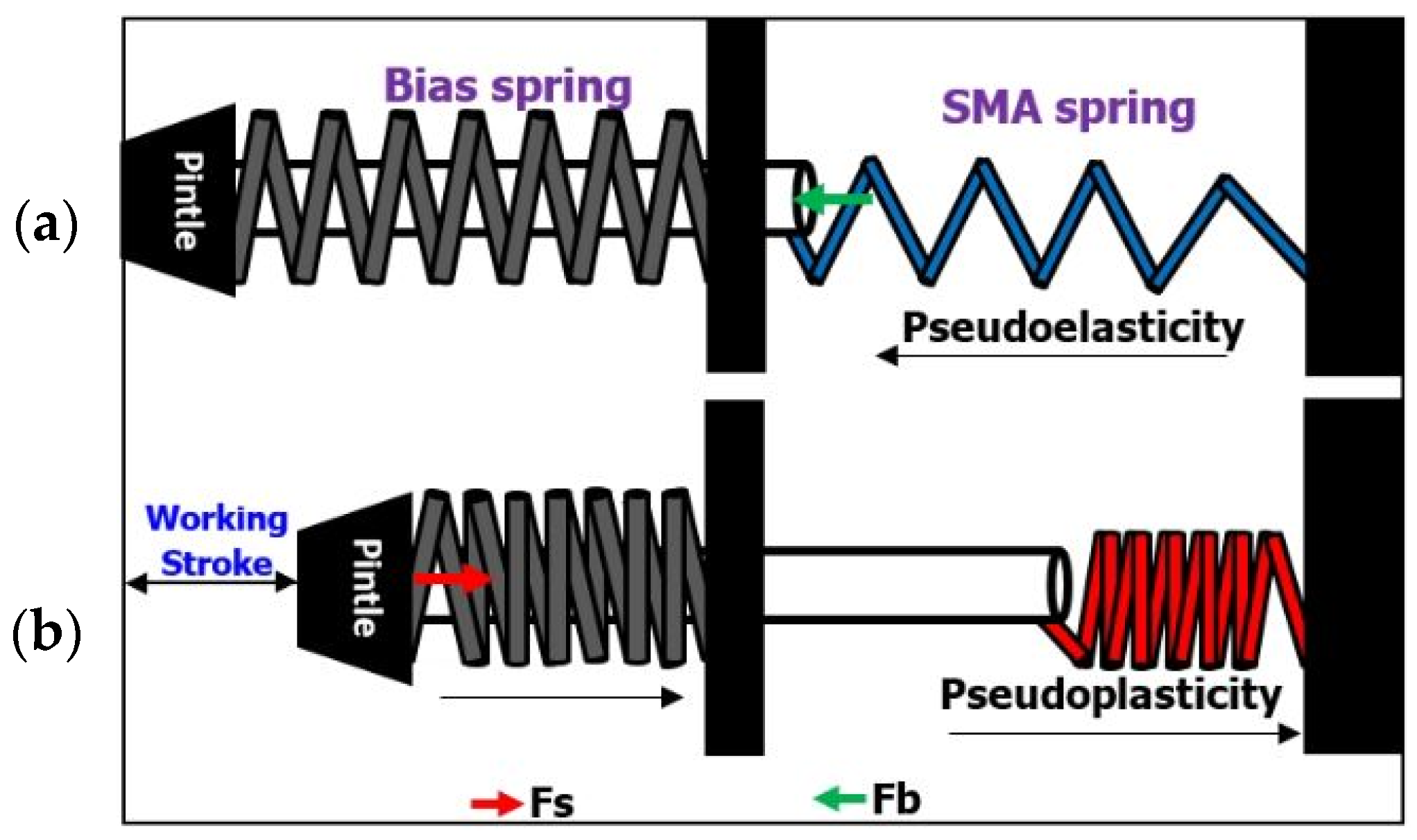
2.2.2. Working Principle of SMA-Based Actuator

The operating principle of the proposed IAC actuator is to close and open the idle air path (bypass) in the throttle body. The SMA spring manages the operation mechanism through its phases such as the martensite and austenite phases. The martensite phase plays a role in the closing state and the austenite phase acts in the opening state of the actuator.
In the closing state, the bias spring extends the SMA spring mechanically with its force ( F b ), as shown in Figure 3a. The force ( F b ) expressed in Equation (1) is transformed according to the operating principle of the SMA-based IAC actuator and expressed by Equation (2). This is a pseudo-elastic phenomenon of SMA spring. Then, the rod assembled with the SMA spring moves into the rod holder and causes the pintle to displace. Within this state, environmental air passes through the throttle valve from entering the engine intake manifold. The stress of the SMA spring induced by mechanical force ( F b ) should be less than the maximum allowable working stress ( σ 0 ) in Table 2. However, the contrary operation is the opening state of the actuator, as shown in Figure 3b.
In the opening state of the IAC actuator, the SMA spring should return to its original position, but generate force ( F s ) to compress the bias spring. The generated force F s is expressed by Equation (2). It depends on the fraction volume ( ϑ ) and the SMA spring displacement ( S ). This force should be able to suppress the mechanical driving force from the bias spring ( F b ). The process is a pseudoplastic phenomenon of the SMA spring. With a compressed bias spring, the pintle with the rod follows the motion of the SMA spring and moves in the opposite direction to open the air flows into the bypass of the throttle body. The thermal mechanical behaviour of the SMA alloy spring is the key parameter to activate the opening state, which will be defined in the phase transformations and control techniques in the next sections.
F b = F p + F t + K s x F s = π d s 3 6 D s d s π D s 2 N s c G s x s + ŋ 1 + ŋ 2 G s ϑ M ϑ A = F p + F t + K b x
where, ŋ 1,2 , are the parameters associated with the stress–strain curve. ϑ M , A , stands for the martensite fraction volume and Austenite fraction volume. d s , D s ,   N s c ,   G s ,   K s , are the SMA spring’s wire diameter, coil mean diameter, number of active coils, shear modulus, and spring constant, respectively. K b is a bias spring constant, x represents spring the displacement or stroke achieved by the pintle, and F p stands for the force that comes from the pressure difference between the inlet and outlet of the bypass. F t represents the transient flow force. F t is in the function of pintle dimensions and air characteristics, as expressed in Equation (3):
F t = L C A π D p s i n φ c 2 ρ A p d x d t
where, L ,   C A ,   D p ,   φ c ,   ρ A ,   p stand for the flowing length, air flow coefficient, pintle diameter, pintle’s conic angle, intake air density, and air pressure difference (pressure of air into the intake manifold and pressure entering the bypass idle air path).

2.3. Analytical Modelling of the Proposed IAC Actuator

Mathematical modelling of the SMA spring is necessary to describe two operability states of the proposed actuator using scientific expressions. From the closing to opening state, the shape memory effect (SME) acts undergo the converted current and SMA models to fulfil the actuation of the IAC actuator, as shown in Figure 4. The function that defines the electric current ( I ) in the converter is dependent on the SMA spring’s size ( A ) and holding temperature circulating into the spring ( T w ) [37]. This function is expressed as follows:
I = F T w , A
The desired temperature of the actuator’s pseudo-plasticity is the final austenite temperature of the SMA spring ( A F ). The converter uses this temperature as the input of the current function to predict the required electric current to supply the SMA spring. The system uses a proportional integrated derivative (PID) controller to achieve fast smooth current output responses. However, the controller input is the output signal from the current function. The scientific behind of this controller is the tuning technique of its gains to the significant values. In this work, the parameterisation of the PID controller is performed with a genetic algorithm (GA) method to obtain the preference controller gains ( K P , I , D ). The objective function to give the optimum gain is a function of the length of the integrated time absolute error (ITAE). The variables are three, the lower boundaries are [0 0 0], and the upper boundaries are [50 50 50]. The system output displays K and fitness values. After using the optimum gains, the output signals from PID pass through the current limiter. To prevent saturation output current signals, we opt to use a saturation limiter with upper and lower boundaries [38]. The output signals of the current converter are shown in Figure 5.
Figure 5a shows the best fitness value of the PID controller’s optimization process achieved within 25 generations. The best fitness value and the last minimum length value of the integrated time absolute error (ITAE) are the key parameters to confirm the optimum gains of the PID controller. Figure 5b shows the frequency of ITAE during controller optimization. The recorded optimum controller gains (K) are 1.03   0.64   0.31 . The controller gain values are important in the controller outputs, accuracy, and time response. Figure 5c shows the electric current output response. The electric current of 2 A is achieved after 700 ms from multiple simulation duty cycles. This current is enough to heat the SMA spring and becomes the input of the SMA models to activate the operation of the SMA-based actuator. The required SMA models to determine the appropriate responses of the actuator include thermal, constitutive, and kinetic models. The models are arranged consecutively to use controlled electric current as the principal input [7,39]. The SME links the models to operate. However, SME is activated by heating the SMA spring at the final required temperature, as described by the thermal model. The thermal model is expressed by Equation (5). For the actuator to perform those two antagonistic states, the heat transfer of the SMA spring is followed by a heating cycle ( T h c ) for opening and a cooling cycle ( T c c ) for the actuator’s closing process. The temperature response ( T w ) from this model becomes the input of the phase transformation model. The temperature ( T w ) should be between the final martensite temperature ( M F ) and the final austenite temperature ( A F ) in Table 3.
ρ s V s c p d T w d t = I 2 R h s π D s 2 4 T w T e   ( Heat   transfer in   SMA   spring ) T h c = T e + I 2 R h s π D s 2 4 1 e 4 h s D s ρ s c p t ( Heating   cycle ) T c c = T e + T w T e e 4 h s D s ρ s c p t ( Cooling cycle )
where ρ s ,   V s ,   c p ,   I ,   R ,   h s ,   t ,   T e stand for the SMA spring’s density, total volume, specific heat, electric current, electric resistance, convection coefficient, operational time, and ambient temperature, respectively.
The volume fraction ( ϑ ) defines the process of the transformation model. From the volume fraction, this model is divided into three classes such as the martensite (M) to the austenite (A) phase, clarifying the austenite fraction volume ( ϑ A ), austenite (A) to martensite (M) phase to define the martensite fraction volume ( ϑ M ), and twinned ( M t w ) to detwinned ( M d t ) martensite phase to derive the detwinned martensite fraction volume ( ϑ d t ). During the phase transformation process, we set the transformation boundaries of martensite ( ϑ M ) and austenite fraction volume ( ϑ A ), with a maximum ( ϑ M ) of 1 and 0 for ( ϑ A ), as shown in Figure 6. Equations (6) and (7) express the phase transformation processes of volume fraction ( ϑ ). This equation is established based on the phase transformation equation model of the SMA-driven compliant rotary actuator demonstrated by M. Daisuke et al. in 2018 [42] and the operating condition of the proposed actuator. The induced stress during the austenite fraction should be less than the stress of the martensite fraction. However, both stresses could cause the operational strain below the transformation strain ( ϵ t r ).
ϑ M = ϑ A i 1 2 c o s π δ T M δ σ M   M S M F + 1 z a   ( A   to   M   transformation   process ) ϑ A = ϑ M i 1 1 2 c o s π δ T A δ σ A A S A F + 1 z b + 1   ( M   to   A   transformation   process ) ϑ d t = 1 ϑ A ϑ d t i 1 1 2 c o s π δ σ σ + 1 z c + 1 ϑ A   ( M t w   t o   M d t   t r a n s f o r m a t i o n   p r o c e s s )
where,
z a = 1 + δ T M δ σ M M S M F α 1 1 α 1 α 1 , z b = 1 δ T A δ σ A A F A S α 2 1 α 2 α 2 , z c = 1 δ σ ( α 3 1 ) σ α 3   α 3 , σ = σ 0 σ i   ,   δ σ = σ w σ i ,   δ σ M = σ w β M ,   δ σ A = σ w β A , δ T M = T w M s ,   δ T A = T w A S
where A S ,     A F ,   M S ,   M F are the starting austenite temperature, final austenite temperature, starting martensite temperature, and final martensite temperature. These parameters are listed in Table 3. α 1,2 , 3   represent the crystal variable speed coefficients of nitinol, β A , β M are slope limit curves of austenite and martensite, and the other mathematical symbols are defined in Table 2 and Table 3. The twinned crystals’ components are separated during detwinned martensite. However, introducing the stresses in the transformation process of the M t w to M d t defines the deformation of the SMA spring in the martensitic condition. The kinetic model is used to find the total stroke that is moved by the pintle. It is defined by the displacement of the SMA spring from the axial pitch. This displacement includes both the change in the axial pitch of the coils ( P ) and the initial pitch ( P s ) of the SMA spring. Hence, this kinetic model determines the change in vertical pitch ( P ) of each coil in a reasonable working strain of spring wire. The product of ( P ) with the number of active coils ( N s c ) results in the total displacement of the spring if it is added or deducted from the original vertical pitch of the SMA spring. The change in axial pitch of the coils ( P ) is a function of working stress, working strain, SMA spring size and the SMA spring’s generated force, as expressed by the first term of Equation (8):
S = P s + 4 F s P s ε w π D s 2 σ w N s c
where S represents the total stroke moved by the actuator’s pintle, ε w stands for the working strain, and σ w is the working stress. Other variables were defined in the previous paragraphs or in Appendix A at the end part of the article. The working strain ( ε w ) used in this model is from the strain due to elasticity, strain induced by thermal, and induced strain by phase transformation. It is expressed as follows:
ε w = ε i σ w E ϑ A , ϑ d t σ i E ϑ A i , ϑ d t i + ξ ϑ d t ϑ d t i + ϑ A T w ϑ A i T e E ϑ A , ϑ d t = E t w + E A E t w ϑ A + E d t E t w ϑ d t ϑ A = M + ( A M ) ϑ A
In the above, ξ , ∅,   ε i are the transformation modulus, temperature coefficient from the material’s resistance, and initial strain of the SMA spring, respectively. E A , E t w , E d t ,   E ϑ A , ϑ d t represent the austenite young’s modulus, twinned young’s modulus, detwinned young’s modulus, and young’s modulus in austenite and detwinned martensite phase transformations, respectively. Equations (4)–(9) were used to develop the MATLAB algorithms that define the operation of the actuator in the analytical mean. The model-based system design approach (Simulink (R2023b)) was adopted and linked with those algorithms because of the multidomain models of the proposed actuator. Simulation outputs are presented in the results section.

2.4. Numerical Analysis of SMA-Based IAC Actuator

The design process of the actuator requires different verification, evaluation, and validation from one analysis approach to another to obtain a well-operating actuator at the final stage [43]. In this section, we used finite element analysis to validate the analytical simulations in the previous section. Both approaches were performed to open and close the air flowing in the bypass of the throttle body for idle engine speed. The numerical analysis uses COMSOL Multiphysics software (R2023b) to parameterise, geometrise, and simulate the IAC actuator. The analysis was arranged to fulfil the opening and closing operations of the actuator described in Figure 3. Table 4 identifies the numerical simulation workflow from the start to the computation of the outputs but highlights the different settings between the closing and opening state of the actuator.
The model builder uses different physics due to the two operating modes of the actuator. Multibody dynamics is used for the mechanical constraints to simulate the actuator in the closing state while the opening state uses joule heating and thermal expansion physics. After confirming the geometry component with full physics settings, the materials are assigned to the concerned actuator components, as identified in Section 2.1. Table 5 lists the properties of materials assigned to the model, excluding the NiTi properties, which are listed in Table 2 and Table 3. When inserting the NiTi input parameters/properties, the basic and phase transformation properties were separated from the martensite and austenite properties.
In the meshing process of the model, the mesh element size was 0.005 mm, with a free tetrahedral extra fine that uses a geometric shape order of quadratic serendipity, as shown in Figure 7a. The electric current uses a terminal type of current with 2 A. It is assigned on a positive connector to supply the SMA spring for the thermal effect of the actuator operation. Figure 7b shows how the current input causes the electric potential induced into the actuator’s components during the computation of the actuator’s opening state solutions. The SMA spring experienced a greater electric potential of 5.12 V and crossed close to the positive connector. The induced temperature to initiate the shape memory effect in the actuator is shown in Figure 7c. In the SMA spring also, the highest temperature of 54.9 °C was recorded. Numerical solutions will be presented in the Results section.

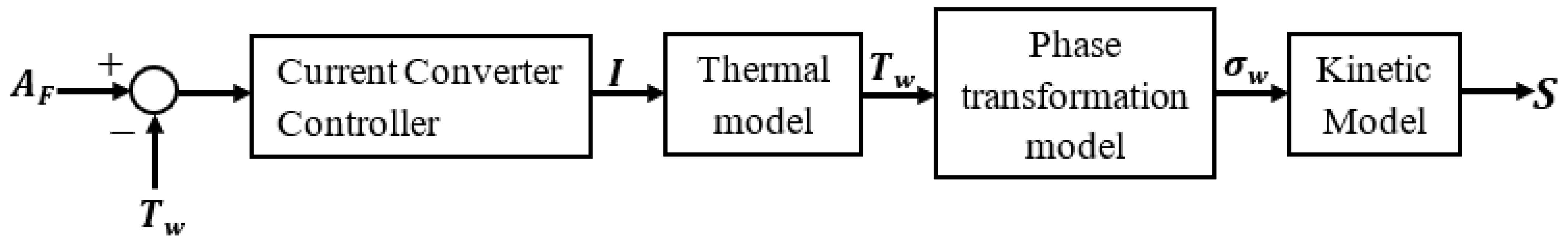
2.5. Performance Evaluation of the Proposed IAC Actuator

In this section, we will evaluate the operability of the designed SMA-based IAC actuator through MATLAB (R2023b) simulation using mathematical algorithms and Simulink. We do not conduct experiments for the proposed actuator at this phase. Still, the same examinations will be performed in this section by integrating the designed actuator into the intake manifold and comparing the engine outputs with the real practical operated engines and literature experimental results. The proposed IAC actuator is assembled into the structure of the throttle body to control the flow of bypass air to the intake manifold through the displacement of its pintle, as shown in Figure 8.
The SMA-based actuator closes the bypass, and fresh air from the environment enters the intake manifold through the throttle valve, as shown in Figure 8a. The actuator is in a closed state, and there is no supply of electric current to the SMA spring. This state of the actuator always occurs whenever the engine is turned off, or the driver presses the accelerator pedal. Figure 8b shows the fresh air flowing through the bypass to enter the intake manifold with an opening actuator. The throttle valve butterfly is in full close with an angle of 90°. This state of the actuator always occurs during engine idling conditions. The dynamic characteristics of air through the bypass and their corresponding engine idling characteristics are expressed in Equations (10)–(13). The main inputs of the equations forming the algorithms in this section include the actual parameters for the spark ignition engine from previous research with experiments [44,45,46] and practical engines [47,48]. The triggering signal from the SMA-based IAC actuator is the opening and closing strokes that vary with time ( S ).
m ˙ A t = D p sin φ c S t P a t m ( t ) R T a t m t 1 2 2 P i n t P a t m t 1 P i n t P a t m t 1 2
where m ˙ A ,   T a t m ,   P a t m ,   P i n ,   R are the air mass flow rate through the pintle of the SMA-based IAC actuator, ambient temperature, atmospheric pressure, air pressure in the intake manifold, and air constant with a value of 287.05   ( J / k g ° C ) . The opening or closing stroke ( S t ) of the actuator describes the air mass flow rate through the bypass ( m ˙ A ) before reaching the intake manifold. The longer the opening stroke of the actuator, the more flowing air enters the intake manifold. This air mass flow rate was used to define the other characteristics of the engine in idle mode.
d d t P i n t = R T i n t V i n m ˙ A t m ˙ e n t 1 + 1 λ t s t
In the above, T i n ,   V i n ,   m ˙ e n , λ represent the temperature in the intake manifold, the volume of the intake manifold, the air mass flow rate that passes through and induced by the engine, and the air–fuel ratio. s t is the stochiometric air–fuel ratio, with a value of 14.7 for the spark ignition engine.
m ˙ e n t = P i n t 2 R T i n t ν e P i n t , ω e n t V p ω e n t 2 π
where ν e , V p ,   ω e n are the volumetric efficiency, piston displacement volume, and engine speed.
T e n t = η H l V p 4 π λ s t m ˙ e n 1 + 1 λ t s t t 2 π ω e n t ω e n t 2 π ω e n t η f 4 π V p P e n t P i n t V p 4 π
where T e n ,   η ,   η f ,   H l stand for the torque produced by the engine during the idle operating mode, ignition parameter, piston’s friction coefficient, and heating due to ignition. The engine modelling equation completed by Gharib et al. [47] and the input parameters form the basis of the equation used to compute the idle engine torque output. Then, we simulated the idle engine speed in revolutions per minute using the generated engine torque and the engine’s load torque. The product of the idle engine speed in radians per second and torque gives the total power output of the engine in watts [49].

3. Results and Discussion

This section presents the findings obtained from the methods discussed in the previous section. It includes the results of analytical analysis, numerical simulations, and integration of the SMA-based IAC actuator into the automotive engine’s intake manifold. Therefore, the discussions will bear the results in line with the IAC actuator’s operations.

3.1. Analytical Results

Analytical simulation results were obtained based on the equations in the analytical method. Figure 9a shows the extension displacement of the shape memory alloy spring from the input mechanical driving force ( F b ). The extension displacement of the SMA spring can be the same as the closing stroke moved by the pintle of the IAC actuator during the closing state. The SMA spring keeps stretching as the input force increases. With the maximum force of 2.39 N, the displacement reached 6.26 mm. However, a coil spring (bias spring) pulled another coil spring (SMA spring), and the displacement curve became rough because the coils were not stretching equally.
The heating and cooling cycles of the SMA spring are shown in Figure 9b. Before 1 s, the heating cycle curve rises from the ambient temperature (25 °C) to the final austenite temperature (50.5 °C), but the final one was achieved at 3.8 s. The main input here was the controlled current (I) from the current converter. The heating cycle remained active when the actuator opened until the SMA spring’s current supply stopped. The choice of a maximum heating temperature of 50.5 °C prevents an actuator from overheating and high electricity consumption. It reduces the time needed to cool it down for another operational state. However, the cooling cycle curve starts to fall after 1.2 s of off-current supply. It takes 4.75 s to complete cooling the SMA spring from the maximum heating temperature to the ambient temperature of 25 °C. It implies that the time required to cool the SMA spring is more than its heating time. Figure 9c shows the generated force of the SMA spring used to compress the bias spring and regain its position. The generated force is zero when the temperature of the heating cycle is between 25 °C and 30 °C. The increasing temperature provides the rise of the generated force. With maximum heating temperature, the spring generates its maximum force of 2.46 N. However, the variation in output force generated by the SMA spring depends on the supplied current, as shown in Figure 9d. This force increases proportionally with the electric current supplied to the SMA spring increases. The current of 2 A provides the highest generated force of 2.46 N. The rising curve of force is active every time the current is on and starts descending directly after the supply current is off for all force curves. Figure 9e shows the displacement of the SMA spring under the electrical supply. The extended coils of the SMA spring return to their original positions when it heats up, causing the spring to regain its original length. In 3.8 s, the maximum settling displacement of 6.5 mm is reached. This displacement of the SMA spring from the input current can be the same as the opening stroke moved by the actuator’s pintle.
The fraction volume curve that defines the transformation of the SMA spring is shown in Figure 10a. According to this curve, the SMA spring’s operability ranges from 0.01 to 0.14 for the austenite fraction volume and 1 to 0.5 for the martensite fraction volume. However, no fraction volume curve passes the settled maximum fraction volume of martensite and austenite. With more repeating cycles, the required temperature for phase transformation is lower. The applied maximum temperature is 54 °C instead of the 50.5 °C to test the performance ability of the SMA spring in the actuator. However, the fraction volume curve confirms the ability of this SMA spring to perform well at such applied temperature without fail. Figure 10b shows the hysteresis curves of stress and strain for both extension and SMA regaining its initial position. The maximum mechanical stress with the SMA spring under extension is 452 Mpa. It is below the maximum allowable working stress ( σ 0 ) of 690 Mpa. The corresponding extension strain to complete the cycle is 0.0219. The regaining process of the SMA spring pulls the bias spring, which causes it to have a maximum stress of 347 Mpa with a strain of 0.016 from the thermal effect. The strength operation of the SMA spring in this actuator is advantageous to the design to prevent overstressing and overstraining of the actuator to increase its life span. The operating with repeatability of the actuator is shown in Figure 10c,d. The actuator performs 100 operating cycles in 5 s with a time interval of 0.0001. They are very congested but indicate that the stress and strain curves of the 1st cycle are the same as the ones recorded in the 100th cycle. The recorded strain from multiple cycles is below the transformation strain in the material properties. The output stress at the 100th cycle is also less than the maximum allowable stress of the SMA spring. They designate the high repeatability and long-life operation of the SMA-based actuator [50].
Figure 10e shows the change in vertical pitches of the coils of the SMA spring. The vertical pitch of each coil changes to extend during the closing state of the actuator. It starts from the initial pitch and extends until the final displacement of the SMA spring. The displacement from a coil covers the initial vertical pitch and its change. The extension starts from the initial pitch of 2.23 mm and ends at 3.5 mm. Regaining axial pitch starts and the SME boosts to activate the SMA spring to the opening state of the actuator. The pitch is changed in the opposite direction from the extension but does not reach the starting point of the extension stage, because of the residual resistance from the bias spring. The final extension pitch becomes the starting point of the regaining pitch, and the final regaining pitch is 2.3 mm. The change in vertical pitch for extension is 1.27 mm, while the vertical pitch for regaining is 1.2 mm. Figure 10f shows the IAC actuator’s closing and opening strokes. The maximum stroke of both states is 6.5 mm, but achieved at different times. The closing stroke curve is not smooth and takes a full simulation time of 5 s to complete. The opening curve from zero to the maximum stroke is smooth and was achieved in 3 s of simulation. The maximum closing stroke is the sum of the total changes of axial pitches and the initial pitch, and the maximum opening stroke is the total change in the axial pitches for regaining. The maximum stroke was settled based on the existing operating space of the pintle from previous research on idle engine speed [51,52,53]. The quick opening of the actuator is required to facilitate the idle speed activation in a short time.

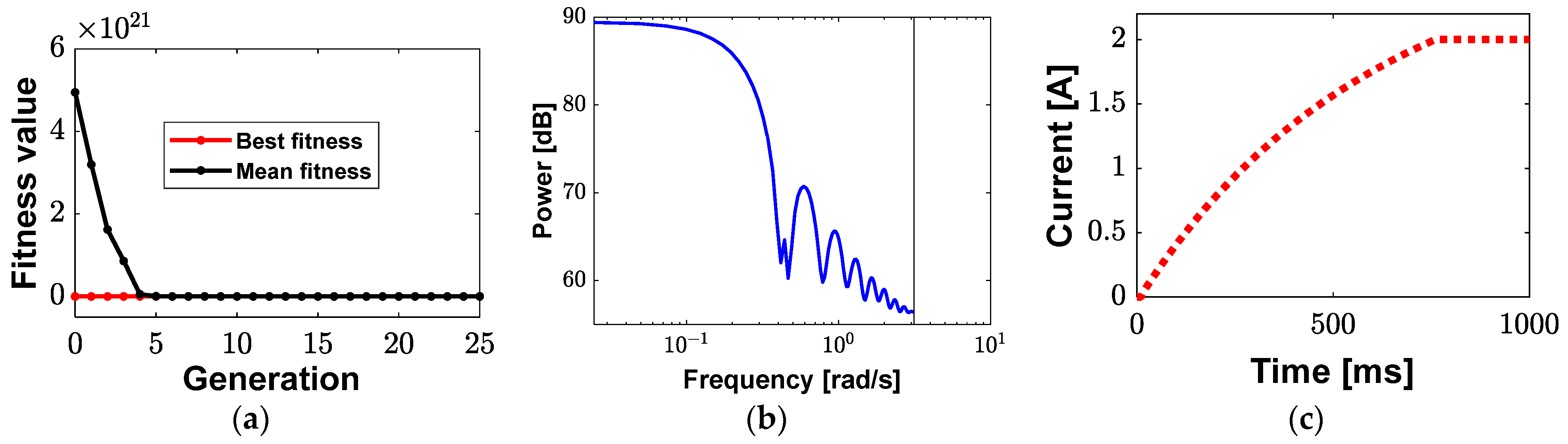
3.2. Numerical Simulations

The numerical simulation results were recorded when the convergence plot was fully generated with the final minimum estimation error of the solution process for the selected nonlinear solver, as shown in Figure 11. It includes both physical interfaces in Table 4 that identify the operational states of the proposed actuator. Although the starting and ending iteration numbers for the operational states differ, they both end with the same estimation error of 10−3. The opening state ends at the 186th iteration number and the closing state starts at the previous state’s last iteration number and ends at the 489th iteration number.
Figure 12 shows the numerical results of both the actuator’s opening and closing operation states. They use the internal structure of the actuator that defines its operational mechanism in Figure 3. The external structure is hidden to prevent the use of results with multi-sliced graphs of results to present the internal structure, which can cause some confusion in analysis.
The extension of the SMA spring activates the closing position of the actuator. It allows the rod and pintle to move in a downward position. However, the stretching of the SMA spring experiences a maximum stress of 461 MPa, while the other parts of the actuator are less stressed, as shown in Figure 12a. It is noticed that there is a difference of 9 MPa between the numerical and analytical maximum stresses. The difference between the numerical output stress and allowable maximum stress of the SMA spring is 229 MPa. It defines the operability of the actuator for a long time without overstressing. Figure 12b shows the strain of the actuator during the closing state with a maximum strain of the actuator that is recorded on the SMA spring. This strain was below the transformation train prescribed in the SMA properties, with a strain difference of 0.3% between them. Figure 12c shows the displacement that is moved by the pintle to close the IAC actuator. The red colour that indicates the maximum displacement appears on the parts which play a role in the pintle’s movements. The red colour on the bias spring comes from the settings chosen to keep the axial pitch of this spring and this spring is identified as the force F b during simulation. The maximum closing displacement of the actuator is 6.48 mm, which indicates a difference of 0.02 mm from the analytical simulation. Figure 12d shows the stress of the actuator during the opening process. The maximum stress is 359 MPa, which appears in the springs. The SMA spring compresses the bias spring to regain its initial position and pulls the rod with a pintle to move upward, which leads to high stress like a bias spring. The color bar of stress clearly shows the bias spring as a part of the actuator that experiences stress. This stress is the lowest compared to the closing stress and the permissible working stress of the SMA spring. The strain from the actuator’s opening state is shown in Figure 12e. Based on a predefined colourmap of the actuator’s strain for the opening state, the bias spring shows the highest strain, and the SMA spring follows it. However, the recorded maximum strain of 2% is lower than the allowable working strain of the spring made from steel, which is between 15% and 20% [54,55]. This strain is also below the maximum strain transformation of the SMA spring. Figure 12f shows the displacement of the actuator to the opening state. The maximum displacement is 6.42 mm, defined by the SMA spring moving upward with the rod and pintle to regain its initial position after compressing the bias spring. There is a difference of 0.06 mm between the closing and opening displacements from the residual energy of the SMA spring after mechanical force application. The coils’ axial pitches of the bias spring were changed, which caused the bias spring to be recorded as the highly displaced part of the actuator. The moving parts, like the rod and pintle in this position, move back to their initial positions. During the design, the desired actuator’s stroke was 6 mm. The decimal values outside of the desired stroke are the operation tolerance. The nature of each analysis method causes apparent differences between numerical and analytical results [56,57]. In the analytical analysis, the solutions were exact based on the inputs we inserted into the equations for forming and material properties. However, numerical analysis provides approximate solutions based on the inputs, material properties assigned, and others already in COMSOL Multiphysics, as well as a nonlinear solver with high computing capability.

3.3. Performance Evaluation Outputs

The results from the performance ability of the designed IAC actuator in the engine’s air intake system are presented here. They are compared to previous studies with experiments and practical engines operating in idle mode. This section also verifies the key parameters and inputs from the practical engines, which may reduce the cost of experiments and manufacturing the proposed IAC actuator. The air mass flow rate through the bypass when the IAC actuator opens is shown in Figure 13a. It describes the amount of air that flows into the intake manifold per defined time. The air mass flow rate in a steady state is 2.76 × 10 3   k g / s after 6 s of simulation. The air mass flow rate is a triggering characteristic of idle engine operation. The IAC actuator’s stroke defines the amount of this air mass flow rate. Figure 13b shows the air pressure through the intake manifold. It is a critical parameter after the air mass flow rate to characterise the intake manifold of an engine operating in idling mode. It is steadily sated after 6 s with an air pressure of 6.06 × 10 4   P a . The air mass flow rate variation determines how air pressure changes in the intake manifold. The intake manifold’s air pressure is higher with the SMA-based IAC actuator than in the literature study from reference [53], and the air pressure difference in these results is 1.56 × 10 4   P a .
Figure 14a shows the output torque and power of an engine that operates in idling mode. Engine torque is the first output performance characteristic to measure in the simulation. The maximum idling torque is 31.08 Nm. This torque response is steadily stated at 5.3 s with 25 Nm. However, the steady state of output power is 16.5 Kw at the same time as the torque. The maximum simulated idle engine power is 19.78 Kw. The results demonstrate an improvement in engine idle torque of 1.24% and power of 1.236% compare with the experimental results from the previous works in the literature [48,51].
Figure 14b shows the speed of the running engine in idle mode. The output speed curve after 5.3 s of simulation is in a steady state with 650 RPM, and the maximum idling speed is 743.8 RPM. All simulated steady-state values are between the maximum and minimum idle performance output characteristics of the practical operated engine. Furthermore, the enhancement of engine idling speed is also shown by comparing with the experimental results from previous research, as cited in references [47,48,51,52,58]. This means the performance improvement of the engine during idling conditions with the designed IAC actuator is achieved. The engine idling characteristics concerning the IAC actuator’s performance are shown in Figure 15. As the actuator’s opening stroke increases, the engine’s idling torque and speed increase, but in different ways. The maximum idling torque of 31.08 Nm is attained with an opening stroke level of 3.8–4.1 mm and a corresponding idling speed of 540.6 RPM. At an opening stroke level of 5.975 mm, the engine reaches its maximum idling speed of 743.8 RPM, and its corresponding idling torque of 24.7 Nm. With this IAC actuator, the engine cannot stall from the torque disturbance or speed variations. Thus, the operating performance of the proposed SMA actuator contributes to the engine’s good idling characteristics.

4. Conclusions

In this study, a novel SMA-based idle air control actuator for automotive engines was proposed to improve the engine’s idling conditions. The innovative idle air control actuator uses shape memory alloy (SMA) smart material as a new technology to activate and control the idling mode of the engine. The inherent characteristics of SMAs, particularly reversible phase transformations in response to thermal changes, were harnessed to create an IAC actuator that is not only simple in structure and compactness but also possesses energy efficiency actuation capabilities with only 2 A of supplied electric current. Through mathematical modelling in analytical analysis and numerical analysis using COMSOL Multiphysics software (R2023b), it was demonstrated that the SMA-based IAC actuator effectively modulates air intake during engine idle mode. This level of idling control contributes significantly to the overall idling efficiency of the engine, addressing key challenges in achieving good performance during idling conditions. The successful control strategy with the PID controller in SMA spring models further enhances the adaptability of the SMA-based IAC actuator’s full opening state in 3 s and attaining the engine’s idling speed of 743.8 RPM. The operability of the actuator at low stress within multiple cycles permits SMA material to be a viable and robust solution for the demanding conditions of real-world vehicle applications. Finally, the looking forward ongoing research will focus on refining the actuator’s design with optimizing control not based on the existing actuators but on the engine’s idling conditions, multiple experiments, and practical implementation of this actuator in a real spark ignition engine to validate the simulation results and address any potential challenges associated with its integration into diverse vehicle platforms.

Author Contributions

Conceptualization, P.T., J.W.S. and S.-B.C.; software, P.T.; formal analysis, P.T.; investigation, P.T.; writing—original draft preparation, P.T.; writing—review and editing, S.-B.C. and J.W.S.; supervision, J.W.S. All authors have read and agreed to the published version of the manuscript.

Funding

This work was supported by the National Research Foundation of Korea (NRF) grant funded by the Korea government (Ministry of Science and ICT, MSIT) (No. 2023R1A2C1007973). This research was supported by the MSIT (Ministry of Science and ICT, MSIT), Korea, under the Grand Information Technology Research Center support program (IITP-2024-2020-0-01612) supervised by the IITP (Institute for Information & communications Technology Planning & Evaluation).

Data Availability Statement

Data is contained within the article.

Conflicts of Interest

The authors declare no conflicts of interest.

Appendix A. Mathematical Variables and Their Descriptions

VariableDescriptionVariableDescription
. b Indication of Bias spring A SMA spring’s area
. s Indication of SMA spring ρ s Density of SMA spring
C f Shear stress correction factor V s The total volume of SMA spring
D b 0 The outer coil diameter of the bias spring c p Specific heat
T c c Cooling cycle R The electric resistance of the SMA spring
d b The wire diameter of the bias spring h s Convective coefficient
i s Spring index t Operational time
τ m Spring’s maximum shear stress T e Ambient temperature
F p Force from the pressure difference between the inlet and outlet of the bypass F b A mechanical driving force to extend the SMA spring
K s Spring constant of SMA spring T h c Heating cycle
K b Spring constant of bias spring A F Austenite final temperature
F s Generated force by SMA spring to compress the bias spring A S Austenite starting temperature
d s SMA spring’s wire diameter M F Martensite final temperature
D s SMA spring’s coil mean diameter M S Martensite stating temperature
N s c SMA spring’s number of active coils ϑ A Austenite fraction volume
F t Transient flow force ϑ M Martensite fraction volume
x Spring displacement ϑ d t Detwinned martensite fraction volume
ŋ 1 , 2 Parameters associated with the stress–strain curve Temperature coefficient from material’s resistance
ε w SMA spring working strain G s SMA spring’s shear modulus
ϑ 1 Tensile detwinned martensite P Change in vertical pitch for spring
ϑ 2 Compressive detwinned martensite α 1 , 2 , 3 Cristal variable speed coefficients of Nitinol
ϵ t r Transformation strain ρ A Density of air to flow in the intake manifold
p Air pressure difference β A Slope of Austenite limit curve
L Air Flowing length β M Slope of martensite limit curve
C A Air flow coefficient ϑ M i Initial martensite fraction volume
D p Pintle diameter ϑ A i Initial austenite fraction volume
φ c Pintle’s conic angle ϑ d t i Initial detwinned fraction volume
ξ Transformation modulus σ i Minimum allowable stress
I Electric current σ 0 Maximum allowable stress
T w Temperature in the SMA spring ε i Minimum strain
S Actuator’s defined stroke P s Initial vertical pitch of the coil spring
m ˙ A Air mass flow through pintle of SMA-based IAC actuator m ˙ e n Air mass flow rate passes through the IAC actuator and induced by the engine
T a t m Ambient temperature V i n Volume of the intake manifold
P a t m Atmospheric pressure T i n Temperature in the intake manifold
P i n Air pressure in the intake manifold λ Air fuel ratio
R Air constant s t Stochiometric air-fuel ratio
T e n Engine torque ν e Volumetric efficiency
η Ignition parameter V p Piston displacement volume
η f Piston’s friction coefficient ω e n Engine speed
H l Heating due to ignition E A Austenite young’s modulus
E t w Twinned young’s modulus E d t Detwinned young’s modulus

References

  1. Chakirov, R.; Vagapov, Y. Rapid Control Prototyping Platform for the Design of Control Systems for Automotive Electromechanical Actuators [Internet]. IFAC Proc. Vol. 2010, 43, 646–651. [Google Scholar] [CrossRef]
  2. Battaglia, A.R.M.; Sellitto, A.; Giamundo, A.; Visone, M. Shape Memory Alloys Applied to Automotive Adaptive Aerodynamics. Materials 2023, 16, 4832. [Google Scholar] [CrossRef] [PubMed]
  3. Dezaki, M.L.; Bodaghi, M.; Serjouei, A.; Afazov, S.; Zolfagharian, A. Adaptive reversible composite-based shape memory alloy soft actuators. Sens. Actuators A Phys. 2022, 345, 113779. [Google Scholar] [CrossRef]
  4. Purohit, R.; Patel, K.K.; Gupta, G.K.; Rana, R.S. Development of Ni-Ti Shape Memory Alloys through Novel Powder Metallurgy Route and Effect of Rolling on their properties. Mater. Today Proc. 2017, 4, 5330–5335. [Google Scholar] [CrossRef]
  5. Kanada, T.; Enokizono, M. A slant type shape memory alloy. J. Magn. Magn. Mater. 2000, 215–216, 573–575. [Google Scholar] [CrossRef]
  6. Benafan, O.; Gaydosh, D.J. Scale-up of NiTiHf shape memory alloy tubes with high torque capability. Smart Mater. Struct. 2019, 28, 085035. [Google Scholar] [CrossRef]
  7. Copaci, D.; Blanco, D.; Moreno, L.E. Flexible shape-memory alloy-based actuator: Mechanical design optimization according to application. Actuators 2019, 8, 63. [Google Scholar] [CrossRef]
  8. Song, G.; Kelly, B.; Agrawal, B.N. Active position control of a shape memory alloy wire actuated composite beam. Smart Mater. Struct. 2000, 9, 711–716. [Google Scholar] [CrossRef]
  9. Fann, K.J.; Su, J.Y. Cold Forming of Ni-Ti Shape Memory Alloy Sheet. IOP Conf. Ser. Mater. Sci. Eng. 2018, 317, 012079. [Google Scholar] [CrossRef]
  10. Costanza, G.; Tata, M.E. Shape Memory Alloys for Aerospace, Recent Developments, and New Applications: A Short Review. Materials 2020, 13, 1856. [Google Scholar] [CrossRef]
  11. Prendota, W.; Goc, K.; Strączek, T.; Yamada, E.; Takasaki, A.; Przewoźnik, J.; Radziszewska, A.; Uematsu, S.; Kapusta, C. Properties of NiTi shape memory alloy micro-foils obtained by pulsed-current sintering of Ni/Ti foils. Metals 2019, 9, 323. [Google Scholar] [CrossRef]
  12. Tomus, D.; Tsuchiya, K.; Inuzuka, M.; Sasaki, M.; Imai, D.; Ohmori, T.; Umemoto, M. Fabrication of shape memory TiNi foils via Ti/Ni ultrafine laminates. Scr. Mater. 2003, 48, 489–494. [Google Scholar] [CrossRef]
  13. Turabimana, P.; Sohn, J.W.; Choi, S.B. A Novel Active Cooling System for Internal Combustion Engine Using Shape Memory Alloy Based Thermostat. Sensors 2023, 23, 3972. [Google Scholar] [CrossRef]
  14. Spaggiari, A.; Spinella, I.; Dragoni, E. Design equations for binary shape memory actuators under arbitrary external forces. J. Intell. Mater. Syst. Struct. 2013, 24, 682–694. [Google Scholar] [CrossRef]
  15. Bhaskar, J.; Sharma, A.K.; Bhattacharya, B.; Adhikari, S. A review on shape memory alloy reinforced polymer composite materials and structures. Smart Mater. Struct. 2020, 29, 073001. [Google Scholar] [CrossRef]
  16. Mizzi, L.; Hoseini, S.F.; Formighieri, M.; Spaggiari, A. Development and prototyping of SMA-metamaterial biaxial composite actuators. Smart Mater. Struct. 2023, 32, 035027. [Google Scholar] [CrossRef]
  17. Serrano, D.; Copaci, D.S.; Moreno, L.; Blanco, D. SMA based wrist exoskeleton for rehabilitation therapy. In Proceedings of the 2018 IEEE/RSJ International Conference on Intelligent Robots and Systems (IROS), Madrid, Spain, 1–5 October 2018; pp. 2318–2323. [Google Scholar] [CrossRef]
  18. Hamid, Q.Y.; Hasan, W.Z.W.; Hanim, M.A.A.; Nuraini, A.A.; Hamidon, M.N.; Ramli, H.R. Shape memory alloys actuated upper limb devices: A review. Sens. Actuators Rep. 2023, 5, 100160. [Google Scholar] [CrossRef]
  19. Liu, Q.; Ghodrat, S.; Jansen, K.M.B. Modelling and mechanical design of a flexible tube-guided SMA actuator. Mater. Des. 2022, 216, 110571. [Google Scholar] [CrossRef]
  20. Jiang, S.; Zhang, Y.; Zheng, Y.; Li, C. Deformation mechanism of hot spinning of NiTi shape memory alloy tube based on FEM. J. Wuhan Univ. Technol. Mater. Sci. Ed. 2012, 27, 811–814. [Google Scholar] [CrossRef]
  21. Sohn, J.W.; Ruth, J.S.; Yuk, D.G.; Choi, S.B. Application of Shape Memory Alloy Actuators to Vibration and Motion Control of Structural Systems: A Review. Appl. Sci. 2023, 13, 995. [Google Scholar] [CrossRef]
  22. Liu, R.; Zhang, C.; Ji, H.; Zhang, C.; Qiu, J. Training, Control and Application of SMA-Based Actuators with Two-Way Shape Memory Effect. Actuators 2023, 12, 25. [Google Scholar] [CrossRef]
  23. Hao, L.; Qiu, J.; Ji, H.; Nie, R. Numerical analysis on shape memory alloy–based adaptive shock control bump. J. Intell. Mater. Syst. Struct. 2018, 29, 3055–3066. [Google Scholar] [CrossRef]
  24. John, S.; Hariri, M. Effect of shape memory alloy actuation on the dynamic response of polymeric composite plates. Compos. Part A Appl. Sci. Manuf. 2008, 39, 769–776. [Google Scholar] [CrossRef]
  25. Koh, J.S. Design of shape memory alloy coil spring actuator for improving performance in cyclic actuation. Materials 2018, 11, 2324. [Google Scholar] [CrossRef] [PubMed]
  26. Soother, D.K.; Daudpoto, J.; Chowdhry, B.S. Challenges for practical applications of shape memory alloy actuators. Mater. Res. Express 2020, 7, 073001. [Google Scholar] [CrossRef]
  27. Bhatt, N.; Gurung, H.; Soni, S.; Singla, A. Effect of biasing conditions on the performance of a SMA spring actuator under thermo-mechanical loading. Mech. Adv. Mater. Struct. 2022, 29, 4599–4613. [Google Scholar] [CrossRef]
  28. Song, G.; Ma, N.; Lee, H.J.; Arnold, S. Design and control of a proof-of-concept variable area exhaust nozzle using shape-memory alloy actuators. Smart Mater. Struct. 2007, 16, 1342–1347. [Google Scholar] [CrossRef]
  29. Fawcett, J.N.; Burdess, J.S. Application of a shape memory alloy in a smart thermal clutch or brake. Proc. Inst. Mech. Eng. Part L J. Mater. Des. Appl. 1999, 213, 21–26. [Google Scholar] [CrossRef]
  30. Palaniappan, S.K.; Rathanasamy, R.; Chellamuthu, S.; Pal, S.K. Development of Shape Memory Alloy Based Quarter Car Suspension System. J. Mech. Eng. Res. 2020, 3, 21–24. [Google Scholar] [CrossRef]
  31. Hübler, M.; Nissle, S.; Gurka, M.; Breuer, U. Active aerodynamic components for automotive applications—FRP spoiler with integrated SMA actuation. ICCM Int. Conf. Compos. Mater. 2015, 2015, 1–6. [Google Scholar] [CrossRef]
  32. Leal, P.B.C.; Savi, M.A. Shape memory alloy-based mechanism for aeronautical application: Theory, optimization and experiment. Aerosp. Sci. Technol. 2018, 76, 155–163. [Google Scholar] [CrossRef]
  33. Chillara, V.S.C.; Headings, L.M.; Tsuruta, R.; Itakura, E.; Gandhi, U.; Dapino, M.J. Shape memory alloy–actuated prestressed composites with application to morphing automotive fender skirts. J. Intell. Mater. Syst. Struct. 2019, 30, 479–494. [Google Scholar] [CrossRef]
  34. Sazonov, E.; Daoud, W.A. Grand Challenges in Wearable Electronics. Front. Electron. 2021, 2, 668619. [Google Scholar] [CrossRef]
  35. Shimoga, G.; Kim, T.H.; Kim, S.Y. An intermetallic niti-based shape memory coil spring for actuator technologies. Metals 2021, 11, 1212. [Google Scholar] [CrossRef]
  36. Ishii, T. Design of shape memory alloy (SMA) coil springs for actuator applications [Internet]. In Shape Memory and Superelastic Alloys; Woodhead Publishing Limited: Cambridge, UK, 2011; pp. 63–76. [Google Scholar] [CrossRef]
  37. An, L.; Huang, W.M.; Fu, Y.Q.; Guo, N.Q. A note on size effect in actuating NiTi shape memory alloys by electrical current. Mater. Des. 2008, 29, 1432–1437. [Google Scholar] [CrossRef]
  38. Mozhi, G.T.; Dhanalakshmi, K.; Choi, S.B. Design and Control of Monolithic Compliant Gripper Using Shape Memory Alloy Wires. Sensors 2023, 23, 2052. [Google Scholar] [CrossRef] [PubMed]
  39. Grigorie, T.L.; Botez, R.M. A Self–Tuning Intelligent Controller for a Smart Actuation Mechanism of a Morphing Wing Based on Shape Memory Alloys. Actuators 2023, 12, 350. [Google Scholar] [CrossRef]
  40. Pillai, R.R.; Murali, G.; Gopal, M. Modeling and Simulation of a Shape Memory Alloy Spring Actuated Flexible Parallel Manipulator. Procedia Comput. Sci. 2018, 133, 895–904. [Google Scholar] [CrossRef]
  41. Qian, H.; Li, H.; Song, G.; Guo, W. A constitutive model for superelastic shape memory alloys considering the influence of strain rate. Math. Probl. Eng. 2013, 2013, 248671. [Google Scholar] [CrossRef]
  42. Kittinanthapanya, R.; Sugahara, Y.; Matsuura, D.; Takeda, Y. Development of a novel SMA-driven compliant rotary actuator based on a double helical structure. Robotics 2019, 8, 12. [Google Scholar] [CrossRef]
  43. Turabimana, P. Design of Automobile Concrete Pump. IOSR J. Mech. Civ. Eng. 2019, 15, 1–5. [Google Scholar] [CrossRef]
  44. Meng, L.; Luo, J.; Yang, X.; Zeng, C. Intake air mass observer design based on extended Kalman filter for air-fuel ratio control on SI engine. Energies 2019, 12, 3444. [Google Scholar] [CrossRef]
  45. Amaral, A.A.D.C.; Saidatin, N.; Mahmud, R.; Maulana, H.S. Experimental Study of Spark Ignition Engine Performance under Different Electronic Control Units, Hole Injectors and Spark Plugs. J. Mech. Eng. Sci. Innov. 2023, 3, 22–29. [Google Scholar] [CrossRef]
  46. Wong, P.K.; Tam, L.M.; Li, K.; Vong, C.M. Engine idle-speed system modelling and control optimization using artificial intelligence. Proc. Inst. Mech. Eng. Part D J. Automob. Eng. 2010, 224, 55–72. [Google Scholar] [CrossRef]
  47. Gharib, A.R.; Gharib, M.R.; Mousavi, S.A.S.; Gorkani, M.R. Control of Throttle Valve in idle speed condition. In Proceedings of the 2010 International Conference on Modelling, Identification and Control, ICMIC, Okayama, Japan, 17–19 July 2010; pp. 394–399. [Google Scholar]
  48. Shamekhi, A.M.; Taghavipour, A.; Shamekhi, A.H. Engine idle speed control using nonlinear multiparametric model predictive control. Optim. Control Appl. Methods 2020, 41, 960–979. [Google Scholar] [CrossRef]
  49. Nikzadfar, K.; Noorpoor, A.; Shamekhi, A.H. Design of an optimal idle speed controller for a turbocharged diesel engine using fuzzy logic method. J. Mech. Sci. Technol. 2012, 26, 2325–2336. [Google Scholar] [CrossRef]
  50. Hashemi, Y.M.; Kadkhodaei, M.; Mohammadzadeh, M.R. Fatigue analysis of shape memory alloy helical springs. Int. J. Mech. Sci. 2019, 161–162, 105059. [Google Scholar] [CrossRef]
  51. Di Cairano, S.; Yanakiev, D.; Bemporad, A.; Kolmanovsky, I.V.; Hrovat, D. Model predictive idle speed control: Design, analysis, and experimental evaluation. IEEE Trans. Control Syst. Technol. 2012, 20, 84–97. [Google Scholar] [CrossRef]
  52. Yin, F.; Sun, J.; Wang, W. Engine Idle Speed Control Research Status and Development Trend; no. Icmmcce; Atlantis Press: Berlin/Heidelberg, Germany, 2015; pp. 1884–1888. [Google Scholar] [CrossRef]
  53. Shulga, E.; Lanusse, P.; Airimitoaie, T.B.; Maurel, S.; Trutet, A. Model Predictive Control of engine intake manifold pressure with an uncertain model. IFAC-PapersOnLine 2021, 54, 335–340. [Google Scholar] [CrossRef]
  54. Wei, H.; Chen, Y.L.; Yu, W.; Su, L.; Wang, X.; Tang, D. Study on corrosion resistance of high-strength medium-carbon spring steel and its hydrogen-induced delayed fracture. Constr. Build. Mater. 2020, 239, 117815. [Google Scholar] [CrossRef]
  55. Nov, Z.; Salvetr, P.; Kotous, J.; Moty, P.; Gokhman, A. Enhanced Spring Steel’s Strength Using Strain Assisted Tempering. Materials 2022, 15, 7354. [Google Scholar] [CrossRef] [PubMed]
  56. Mirzaeifar, R.; Desroches, R.; Yavari, A. A combined analytical, numerical, and experimental study of shape-memory-alloy helical springs. Int. J. Solids Struct. 2011, 48, 611–624. [Google Scholar] [CrossRef]
  57. Zhang, B.; Zeng, S.; Tang, F.; Hu, S.; Zhou, Q.; Jia, Y. Experimental and numerical analysis of the mechanical properties of a pretreated shape memory alloy wire in a self-centering steel brace. Processes 2021, 9, 80. [Google Scholar] [CrossRef]
  58. Yildiz, Y.; Annaswamy, A.M.; Yanakiev, D.; Kolmanovsky, I. Spark-ignition-engine idle speed control: An adaptive control approach. IEEE Trans. Control Syst. Technol. 2011, 19, 990–1002. [Google Scholar] [CrossRef]
Figure 1. Structure of proposed idle air control actuator. (a) Complete 3D assembled model of the actuator; (b) sectioned actuator with all main components (1. Pintle, 2. Rod, 3. Inner housing, 4. Bias spring, 5. O ring, 6. Fixture plate, 7. Bolts-holder, 8. Rod holder, 9. SMA spring, 10. Outer housing, 11. Connecting box, 12. Electric connectors, 13. Vertical support, and 14. Cooling slot).
Applsci 14 04784 g001
Figure 2. Schematic structure of springs in normal state. (a) Bias spring; (b) SMA spring (d: wire diameter, P: vertical pitch, D: coil diameter, and L: free length of the coil).
Applsci 14 04784 g002
Figure 3. Operational mechanism of the actuator: (a) closing state; (b) opening state.
Applsci 14 04784 g003
Figure 4. Shape memory effect (SME) analytical model to operate the actuator.
Applsci 14 04784 g004
Figure 5. Current converter’s characteristics. (a) PID optimization fitness values (Best: 504.366, Mean: 1.8951 × 10¹⁵); (b) power spectrum of integrated time absolute error (ITAE); and (c) output current response.
Applsci 14 04784 g005
Figure 6. Maximum reference of fraction volume in phase transformation.
Applsci 14 04784 g006
Figure 7. Numerical modelling process of the IAC actuator. (a) Generated meshing of IAC actuator model, (b) induced electric potential from the input current flowing into the actuator, and (c) temperature in the actuator to activate shape memory effect.
Applsci 14 04784 g007
Figure 8. Simplified structural representation of engine intake manifold with throttle body holding an SMA-based IAC actuator. (a) Air flowing in the main path with the opening throttle valve and bypass closed by the SMA-based IAC actuator; (b) air passes through the bypass path opened by the SMA-based IAC actuator and full closed throttle valve. (1. Throttle body, 2. Bypass, 3. Throttle valve butterfly, 4. SMA-based IAC actuator).
Applsci 14 04784 g008
Figure 9. Shape memory effect outputs in the operating mechanism of the proposed IAC actuator. (a) Mechanical force versus the extension displacement of proposed actuator caused by bias spring; (b) heating and cooling cycles with used time to the final stage; (c) generated force of SMA spring to pull the bias spring with heating temperature; (d) output generated force of SMA spring produced by different supplied electric current; (e) displacement of SMA spring to regain its normal position.
Applsci 14 04784 g009
Figure 10. Effect of shape memory alloy in actuation mechanism of the proposed actuator. (a) Fraction volume of SMA spring concerning temperature taken during phase transformation; (b) hysteresis curve of stress–strain from the mechanical extension of SMA spring and stress–strain curve during spring regains its initial position; (c) stress of SMA within multiple numbers of operating cycles; (d) operating strain of SMA spring from a multiple number of cycles; (e) the change in vertical pith to the extension and regaining position of the SMA spring for closing and opening states of the actuator; (f) closing and opening strokes of the proposed IAC actuator.
Applsci 14 04784 g010
Figure 11. Solver’s convergence plot of the estimation errors.
Applsci 14 04784 g011
Figure 12. Numerical analysis results of the SMA-based IAC actuator’s closing and opening operating mechanisms. (a) Induced stress of the actuator during closing state; (b) induced strain of the actuator during closing state; (c) closing displacement of the actuator; (d) stress induced by the actuator during opening state; (e) induced strain of the actuator during opening state; and (f) the actuator opening displacement.
Applsci 14 04784 g012
Figure 13. Intake manifold characteristics of idling engine. (a) Air mass flow rate through the bypass to the intake manifold; (b) pressure of air flows in the intake manifold during engine operation in idle mode.
Applsci 14 04784 g013
Figure 14. Performance characteristics of an engine running in idle mode. (a) Idling engine torque and power output; (b) output idling engine speed.
Applsci 14 04784 g014
Figure 15. Effect of the SMA-based IAC actuator’s operating performance on the engine’s idling output characteristics.
Applsci 14 04784 g015
Table 1. Specifications of the spring.
ParameterValue
Bias Spring ( . b )SMA Spring ( . s )
Wire diameter ( d )2 mm1.7 mm
Free length of coil ( L f )23 mm15.5 mm
Coil diameter ( D 0 )16 mm10.2 mm
Spring index ( i s )86
Generated force ( F )2.25 N2.416 N
Number of active coils ( N c )75
Table 2. Properties of SMA spring.
PropertyValue
Maximum allowable stress ( σ 0 ) 690   N m m 2
Minimum allowable stress ( σ i ) 70   N m m 2
Operating number of cycles ( N c y ) 10 5
Operating temperature0–60 ° C
Ambient temperature ( T e ) 25   ° C
Density ( ρ s ) 6.45   g m m 6
Poison’s ratio ( r s )0.33
Electric resistivity_Martensite ( ρ e M ) 8.7 × 10 4   m m
Electric resistivity_Austenite ( ρ e A ) 7.2 × 10 4   m m
Specific heat ( c p ) 0.2   C a l g o C 1
Martensite young’s modulus ( E M )33,500 N m m 2
Austenite young’s modulus ( E A )62,500 N m m 2
Coefficient of thermal expansion ( C t h ) 11 × 10 6   K 1
Maximum pulling force ( F s m a x ) 4   N
Table 3. Phase transformation characteristics.
ParameterValueReference
Martensite starting temperature ( M S ) 38   ° C [40]
Martensite final temperature ( M F ) 26.5   ° C
Austenite starting temperature ( A S ) 42   ° C
Austenite final temperature ( A F ) 50.5   ° C
Slope of Austenite limit curve ( β A ) 7.2   N m m 2 K 1
Slope of martensite limit curve ( β M ) 6.92   N m m 2 K 1
Maximum transformation strain ( ε t r ) 2.3 % [41]
Table 4. Numerical simulation workflow in COMSOL Multiphysics.
Model Builder and SettingIAC Actuator’s Operating Mode
Closing StateOpening State
Physics interfaceStructure Mechanics/Multibody dynamics Structure Mechanics/Joule Heating and Thermal Expansion
StudyStationaryStationary
Physics constraints Rigid fixed domain (supports), Prescribed displacement, (Assigned on the Pintle as the desired displacement), and
Boundary load ( F b used as pressure and assigned on the bias spring)
Fixed constraint (supports), Temperature ( T e ), Ground (negative connector), Electric terminal (positive connector linked with the SMA spring).
Meshing Free tetrahedral extra fine Free tetrahedral extra fine
Solver configurationsStationary nonlinear solver with segregated stepsStationary nonlinear solver with segregated steps
Table 5. Materials and their properties for the model.
Property Material
Stainless Steel 405 (Bias Spring, Rod Holder, and Rod)Low Carbon Steel 1008 (Fixture Plate and Vertical Support)Grey Cast Iron (Housings)Ductile Cast iron (Connection Box)Nitrile Rubber (O Ring)
Young’s modulus 190   G p a 200   G p a 124   G p a 172   G p a 0.855   M P a
Poison’s ratio 0.3 0.29 0.26 0.26 0.43
Density 7800   k g / m 3 7872   k g / m 3 7150   k g / m 3 7200   k g / m 3 1000   k g / m 3
Thermal conductivity 16.2   W / m K 16.2   W / m K 53.3   W / m K 32.3   W / m K 0.33   W / m K
Specific heat capacity 500   J / k g K 450   J / k g K 490   J / k g K 506   J / k g K 1900   J / k g K
Coefficient of thermal expansion 9.9 × 10 6 / K 1.32 × 10 5 / K 9 × 10 6 / ° C 11.6 × 10 6 / ° C 0.48 / ° C
Disclaimer/Publisher’s Note: The statements, opinions and data contained in all publications are solely those of the individual author(s) and contributor(s) and not of MDPI and/or the editor(s). MDPI and/or the editor(s) disclaim responsibility for any injury to people or property resulting from any ideas, methods, instructions or products referred to in the content.

