
Research on Mechanical Properties and Engineering Applications of Inorganic Cementitious Filling Materials in Coal Mine Abandoned Roadways


Abstract
1. Introduction
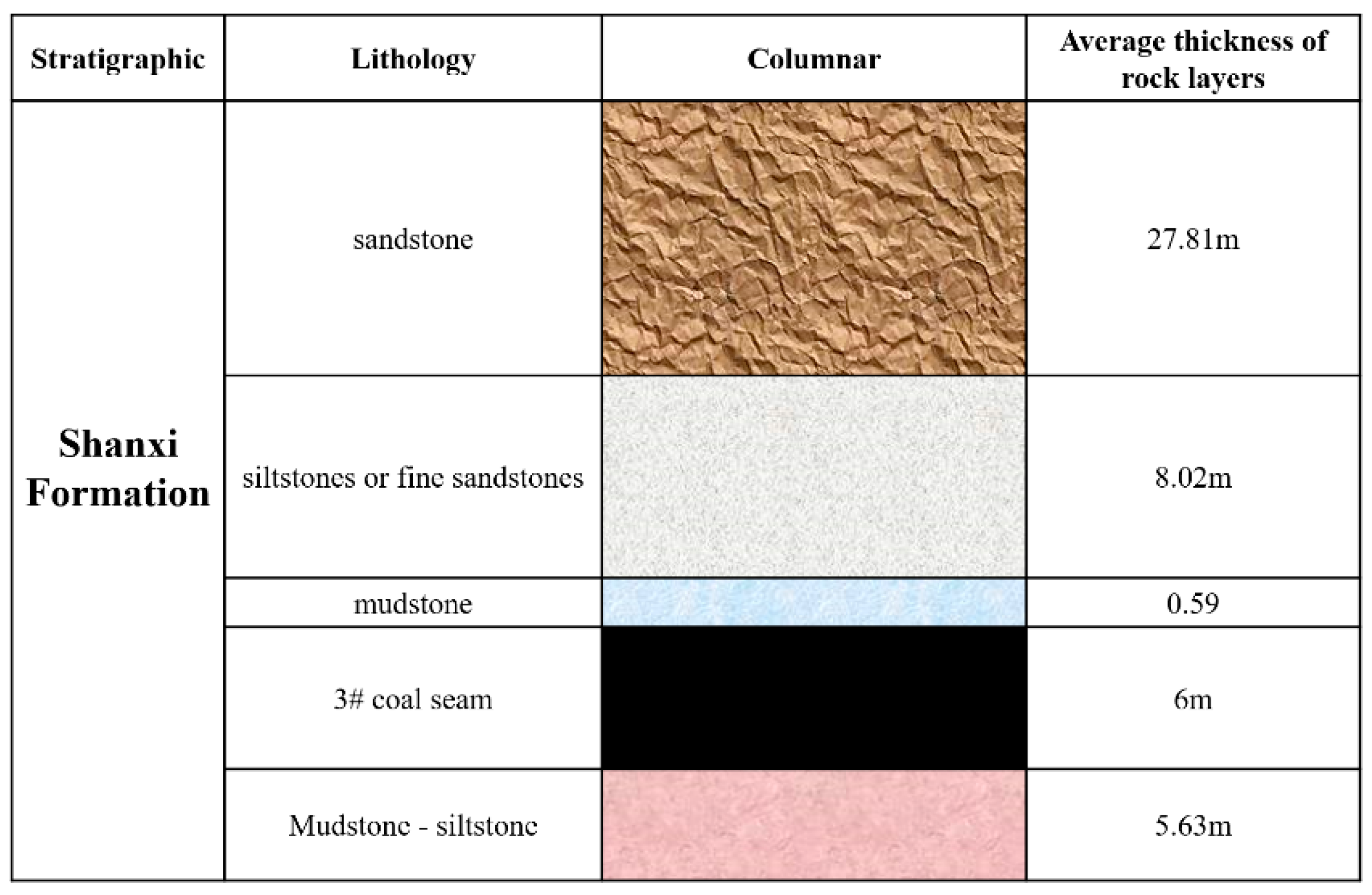
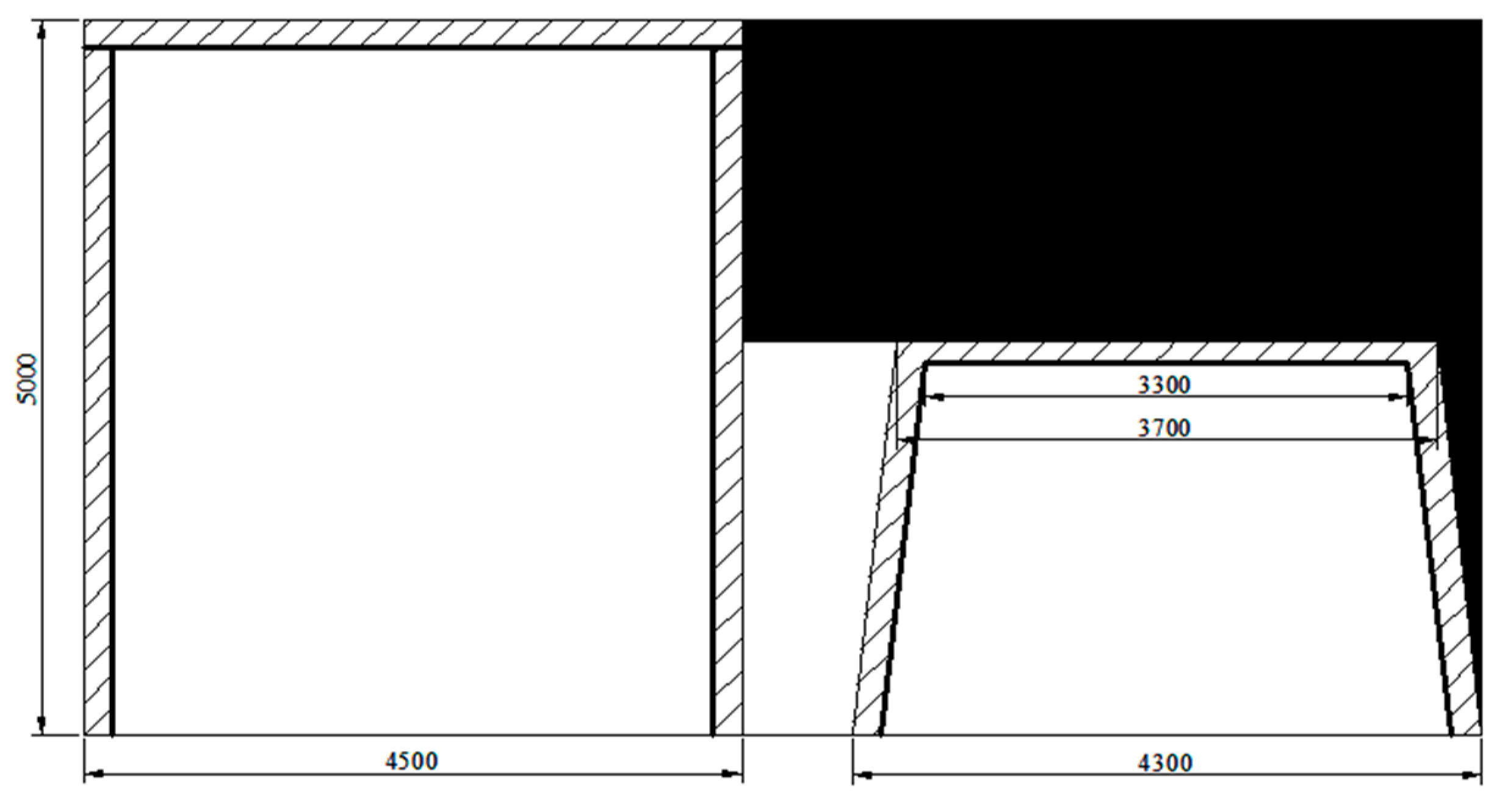
2. Engineering Background
3. Test Materials and Methods
3.1. Test Master Material
3.2. Test Requirements
3.3. Test Methods
4. Analysis of Test Results
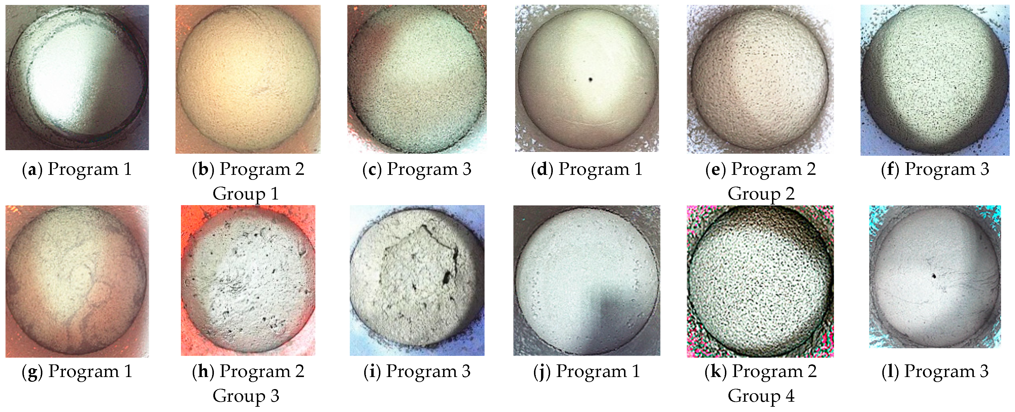
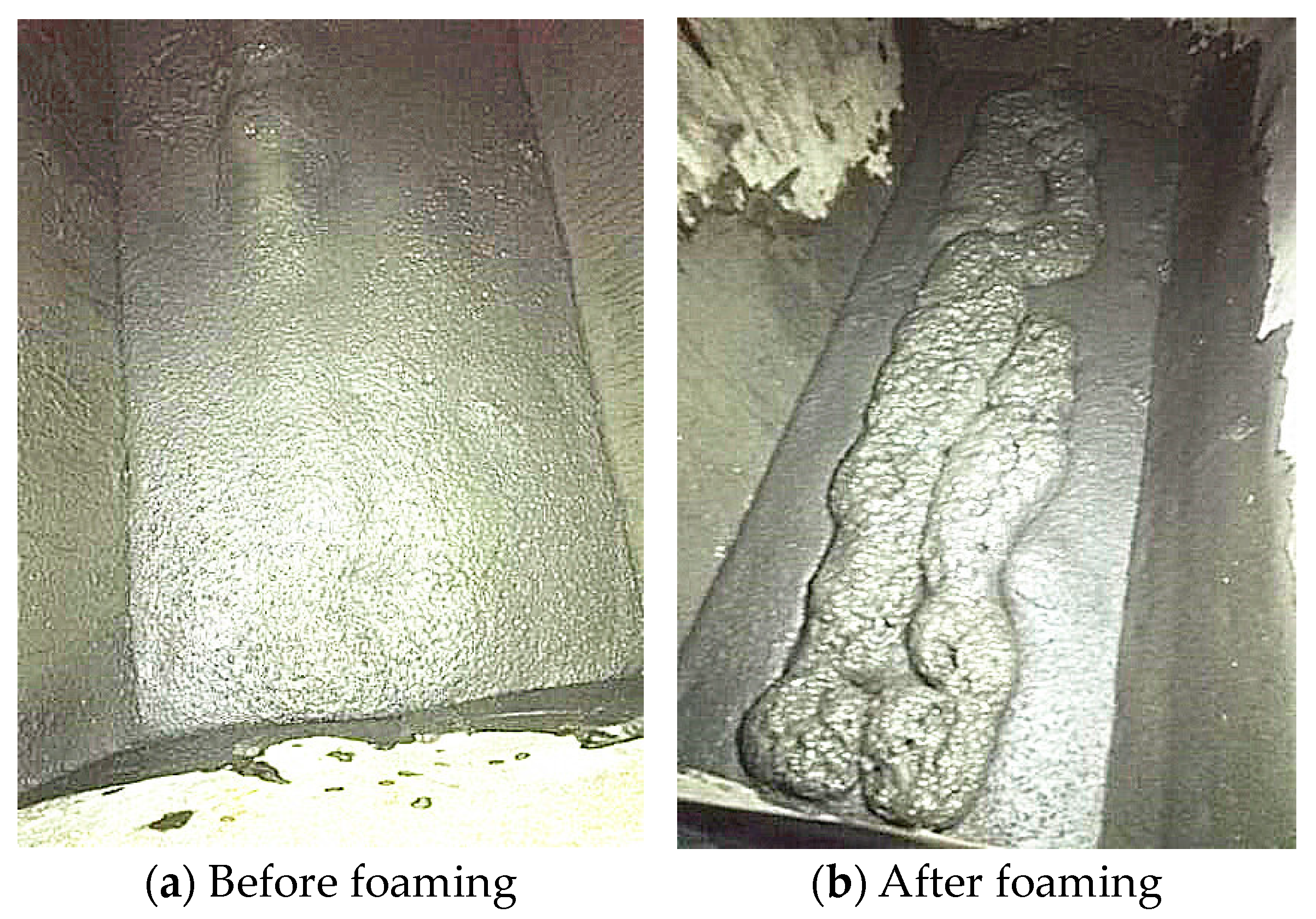
4.1. Test Process and Phenomenon
- (1)
- Initial test phenomenon
- (2)
- Later experimental phenomenon
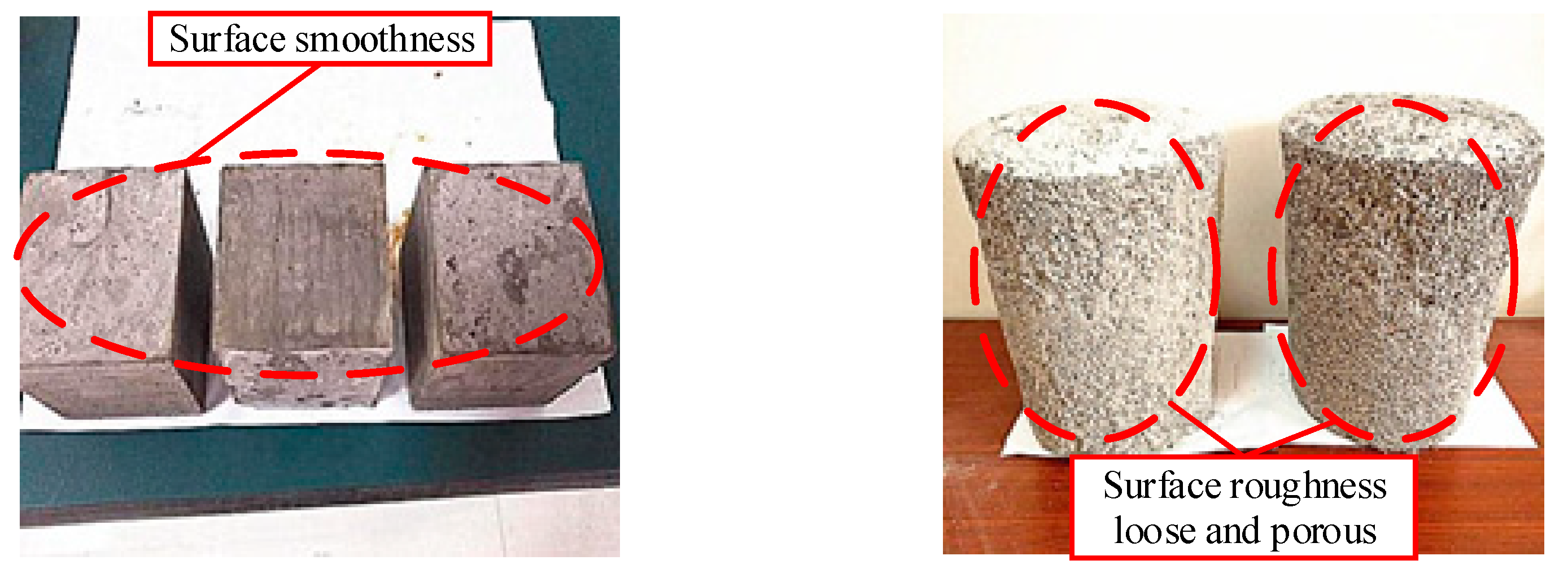
4.2. Analysis of Test Results
4.3. Strength Performance Analysis
- (1)
- Strength test analysis of the first group of specimens
- (2)
- Strength test analysis of the second group of specimens
- (3)
- Strength test analysis of the third group of specimens
- (4)
- Strength test analysis of the fourth group of specimens
5. Working Face Abandoned Roadway Filling Technology Process
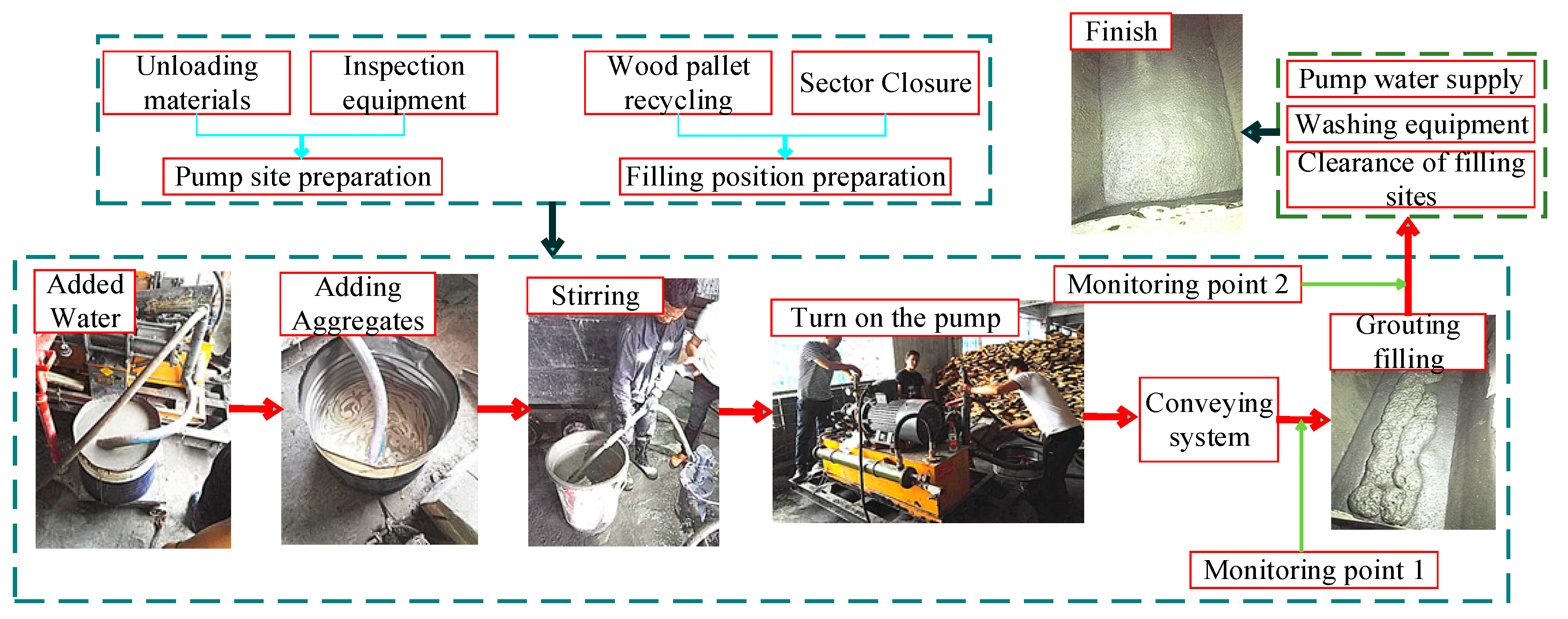
5.1. Conveying and Filling Process
- (1)
- Filling preparation. The unloading worker loads and unloads the grouting material at the material stacking area, while personnel from each work type coordinate operations and prepare the pumping station. Prior to filling, the abandoned roadway should be cleared by removing wooden pallets and erecting temporary containment walls to seal off the section.
- (2)
- Grouting and filling. Following the specified ratio of material components, the mixer will dispense the materials into the mixing bucket for thorough blending. Once the slurry is prepared, start the pump and use the conveyor system to transport the materials to the filling location for grouting. During the filling process of the abandoned roadway, at least two monitoring points should be established to observe the slurry condition and filling progress, respectively.
- (3)
- Cleaning and finishing. After completing the filling of the section, seal the grouting holes, activate the pump to flush water through the system, clean the grouting pipeline, organize the equipment, and prepare for the next section of grouting and filling.
5.2. Field Test of Inorganic Cementitious Material for Abandoned Roadway
5.3. Observation of Mine Pressure
6. Discussion
7. Conclusions
- When the amount of base material B is controlled in a certain proportion, it can not only improve the foaming effect of the slurry but also shorten the condensation time of the slurry and increase the compressive strength of the material. But when the proportion of the B material is more than a certain degree, the strength of the collodion material decreases instead of rising.
- Foaming agent can control the slurry foaming times—the larger the amount of foaming agent, the higher the slurry foaming times. At the same time, it will reduce the compressive strength of the filling material; therefore, it is not a case of “the more, the better” with regard to the amount of foaming agent, and it is combined with the need for the strength of the material to be determined comprehensively.
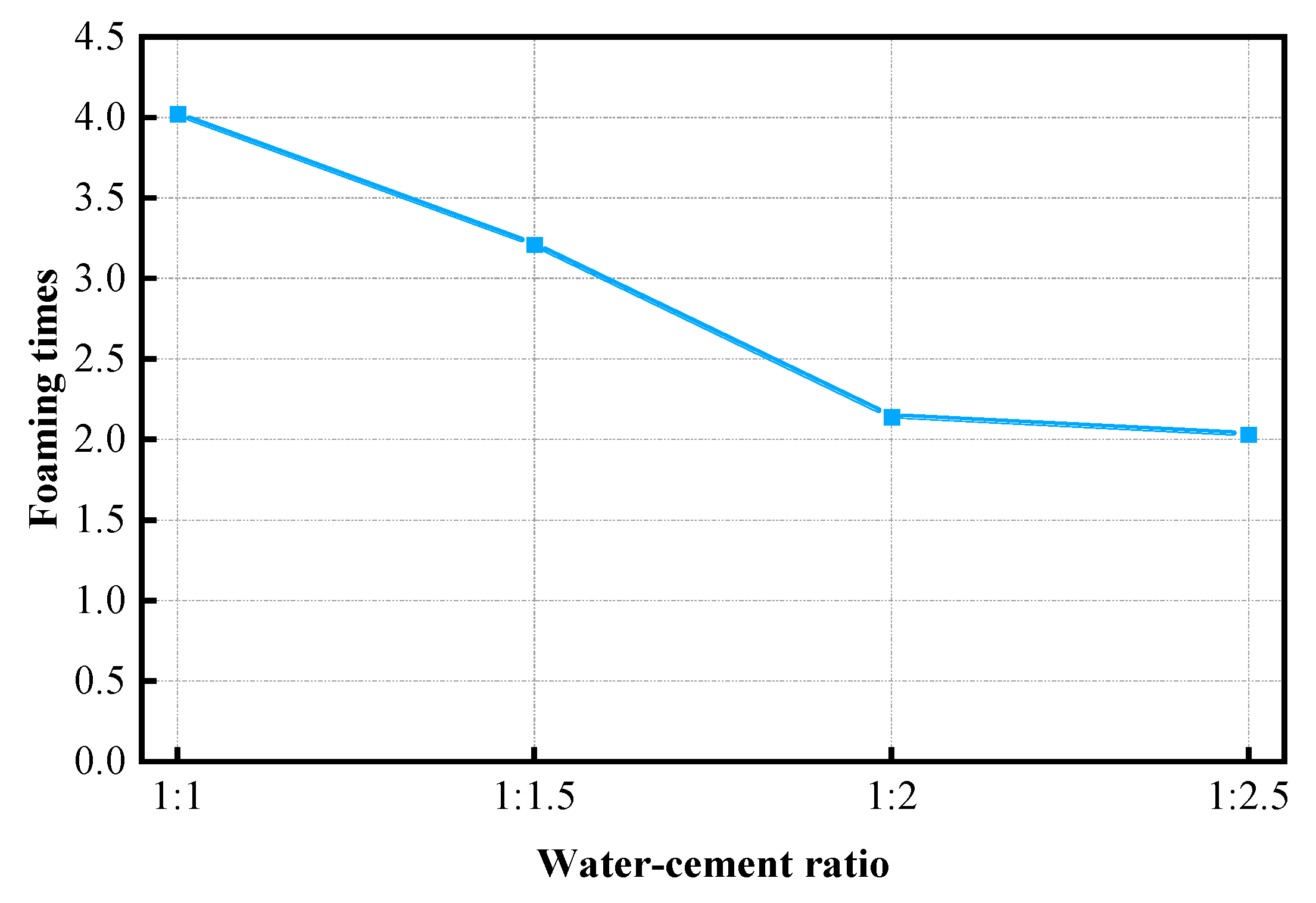
- The water/cement ratio is the main factor affecting the compressive strength of inorganic cementitious materials; the greater the water/cement ratio, the smaller the compressive strength of the material. But the material used to prepare the material is reduced, and thus the cost is lower. Taking into account the need for the material to have a certain strength, a water-cement ratio of 1:1.5 or so is appropriate.
Author Contributions
Funding
Institutional Review Board Statement
Informed Consent Statement
Data Availability Statement
Conflicts of Interest
References
- Wang, C.; Li, G.; Yu, Z.; Xu, B. Stability and Sealing of Abandoned Roadways under High Internal Pressure. Min. Metall. Explor. 2023, 40, 871–884. [Google Scholar] [CrossRef]
- Shi, S.; Miao, Y.; Wu, H.; Xu, Z.; Liu, C. The Stress Evolution of Adjacent Working Faces Passing through an Abandoned Roadway and the Damage Depth of the Floor. Energies 2022, 15, 5824. [Google Scholar] [CrossRef]
- Jiang, Z.; Wang, F.; Miao, K.; Cao, Q. Surrounding Rock Control Technology When the Longwall Face Crosses Abandoned Roadways: A Case Study. Geofluids 2021, 2021, 7867460. [Google Scholar] [CrossRef]
- Yu, Y.; Lu, J.; Pan, Y.; Zhao, X.; Chen, D. Research and Practice on Filling Technology of Fully Mechanized Coal Mining Face through Trend Abandoned Roadway. Sustainability 2021, 13, 9920. [Google Scholar] [CrossRef]
- Li, Y.; Ren, Y.; Wang, N.; Luo, J.; Li, N.; Liu, Y.; Li, G. A Novel Mining Method for Longwall Panel Face Passing through Parallel Abandoned Roadways. Shock Vib. 2021, 2021, 9998561. [Google Scholar] [CrossRef]
- Luo, W.; Yu, Y.; Wang, W. Research on the Mechanism and Control of Strong Mine Pressure in Fully Mechanized Mining Face of Shandong Mining Area When Crossing Abandoned Roadways in the Same Coal Seam. J. China Coal Soc. 2024. [Google Scholar] [CrossRef]
- Meng, S. Mining technology for fully mechanized working face crossing large section abandoned roadway in close distance coal seam. Coal Eng. 2017, 49, 87–90. [Google Scholar]
- Wang, H.; Luo, Y. Industrial Testing on Working Face Passing Abandoned Roadway under Pier Column Filling. Saf. Coal Mines 2014, 45, 46–49. [Google Scholar]
- Deschamps, R.J. Using FBC and stoker ashes as roadway fill: A case study. J. Geo-Tech. Geo-Environ. Eng. 2008, 124, 1120–1127. [Google Scholar] [CrossRef]
- Rashad, A.M. Metakaolin as cementitious material: History, scours, production, and composition—A comprehensive overview. Constr. Build. Mater. 2013, 41, 303–318. [Google Scholar] [CrossRef]
- Scrivener, K.L.; Nonat, A. Hydration of cementitious materials, present and future. Cem. Concr. Res. 2011, 41, 651–665. [Google Scholar] [CrossRef]
- Sun, Y. Preparation system design of filling material with coal gangue as coarse aggregate. Nat. Resour. Sustain. Dev. 2012, 361, 135–138. [Google Scholar] [CrossRef]
- Zhao, G.Y.; Wu, H.; Chen, Y.; Xu, Z.W.; Li, Z.Y.; Wang, E.J. Experimental study on the load-bearing mechanism and compaction characteristics of mine filling materials. J. China Univ. Min. Technol. 2017, 46, 1251–1258. [Google Scholar]
- Yao, Y.; Sun, H.; Jiang, S.; Zhang, R.; Su, D.; Feng, C.; Han, X. Performance and leaching analysis of a novel coal sludge-based backfill material. Clean Technol. Environ. Policy 2013, 15, 657–666. [Google Scholar] [CrossRef]
- Sun, L.; Li, C.; Xu, Z.; Tai, L.; Cao, Y.; Zhang, X. Mitigating Risks in Coal Mining: Simulation-Based Strategy for Oxidation Zone Control Using Inorganic Paste Backfill at the Working Face Corners. Appl. Sci. 2023, 13, 13216. [Google Scholar] [CrossRef]
- Xie, S.; Wang, E.; Chen, D.; Li, H.; Jiang, Z.; Yang, H. Stability analysis and control technology of gob-side entry retaining with double roadways by filling with high-water material in gently inclined coal seam. Int. J. Coal Sci. Technol. 2022, 9, 52. [Google Scholar] [CrossRef]
- Li, T.; Chen, G.; Qin, Z.; Li, Q.; Cao, B.; Liu, Y. The gob-side entry retaining with the high-water filling material in Xin’an Coal Mine. Geomech. Eng. 2020, 22, 541–552. [Google Scholar]
- Liu, Y.F.; Wu, X.H.; Zhu, T.; Wang, X.J.; Zhang, G.Y.; Wang, Z.G. Influence of Mechanical Properties of Filling Paste on Overlying Strata Movement and Surface Settlement. Shock Vib. 2022, 2022, 4687200. [Google Scholar] [CrossRef]
- Yu, Y. Development for the New Backfilling Cementing Materials and Research on Its Properties in Coal Mine. Ph.D. Thesis, China University of Mining & Technology, Beijing, China, 2017. [Google Scholar]
- Wu, W. Investigation on uniaxial compressive strength of flocculated slurry backfill materials for minefill applications. Rock Soil Mech. 2010, 31, 3367–3372. [Google Scholar]
- Cui, Z.; Sun, H. The preparation and properties of coal gangue-based site paste-like backfill material. J. China Coal Soc. 2010, 35, 896–899. [Google Scholar]
- Zheng, B.; Zhou, H.; He, R. Experimental Research on Coal Gangue Paste Filling Material. J. China Univ. Min. Technol. 2006, 23, 460–463. [Google Scholar]
- Zhang, M.; Tian, Q.; Xu, L.; Kong, D.; Dai, J.; Guo, H. Status and Prospects of Research on Foamed Cement. Bull. Chin. Ceram. Soc. 2014, 33, 2547–2551. [Google Scholar] [CrossRef]


| Group Number | Program | Water Content/kg | A Material Content/kg | B Material Content/g | Foaming Agent Content/g | Water-Cement Ratio |
|---|---|---|---|---|---|---|
| Group 1 | Program 1 | 1 | 1.5 | 0 | 50 | 1:1.5 |
| Program 2 | 1 | 1.5 | 0 | 100 | 1:1.5 | |
| Program 3 | 1 | 2.5 | 0 | 100 | 1:2.5 | |
| Group 2 | Program 1 | 1 | 1.5 | 80 | 100 | 1:1.5 |
| Program 2 | 1 | 1.5 | 120 | 100 | 1:1.5 | |
| Program 3 | 1 | 1.5 | 150 | 100 | 1:1.5 | |
| Group 3 | Program 1 | 1 | 1.5 | 130 | 50 | 1:1.5 |
| Program 2 | 1 | 1.5 | 130 | 100 | 1:1.5 | |
| Program 3 | 1 | 1.5 | 130 | 150 | 1:1.5 | |
| Group 4 | Program 1 | 2 | 2.0 | 100 | 140 | 1:1.0 |
| Program 2 | 1 | 1.5 | 100 | 140 | 1:1.5 | |
| Program 3 | 1 | 2.0 | 100 | 140 | 1:2.0 |
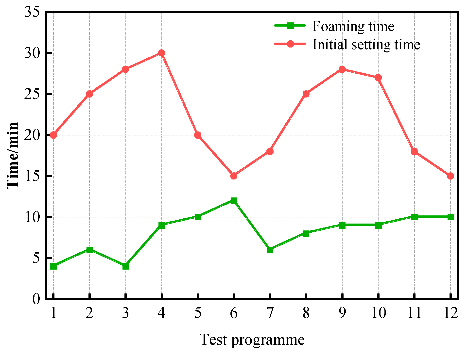
| Group Number | Program | Foaming Time/min | Initial Setting Time/min | Foam Multiple |
|---|---|---|---|---|
| Group 1 | Program 1 | 4 | 20 | 1.64 |
| Program 2 | 6 | 25 | 2.83 | |
| Program 3 | 4 | 28 | 2.03 | |
| Group 2 | Program 1 | 9 | 30 | 2.34 |
| Program 2 | 10 | 20 | 2.85 | |
| Program 3 | 12 | 15 | 2.94 | |
| Group 3 | Program 1 | 6 | 18 | 1.83 |
| Program 2 | 8 | 25 | 2.86 | |
| Program 3 | 9 | 28 | 3.54 | |
| Group 4 | Program 1 | 9 | 27 | 4.02 |
| Program 2 | 10 | 18 | 3.21 | |
| Program 3 | 10 | 15 | 2.14 |
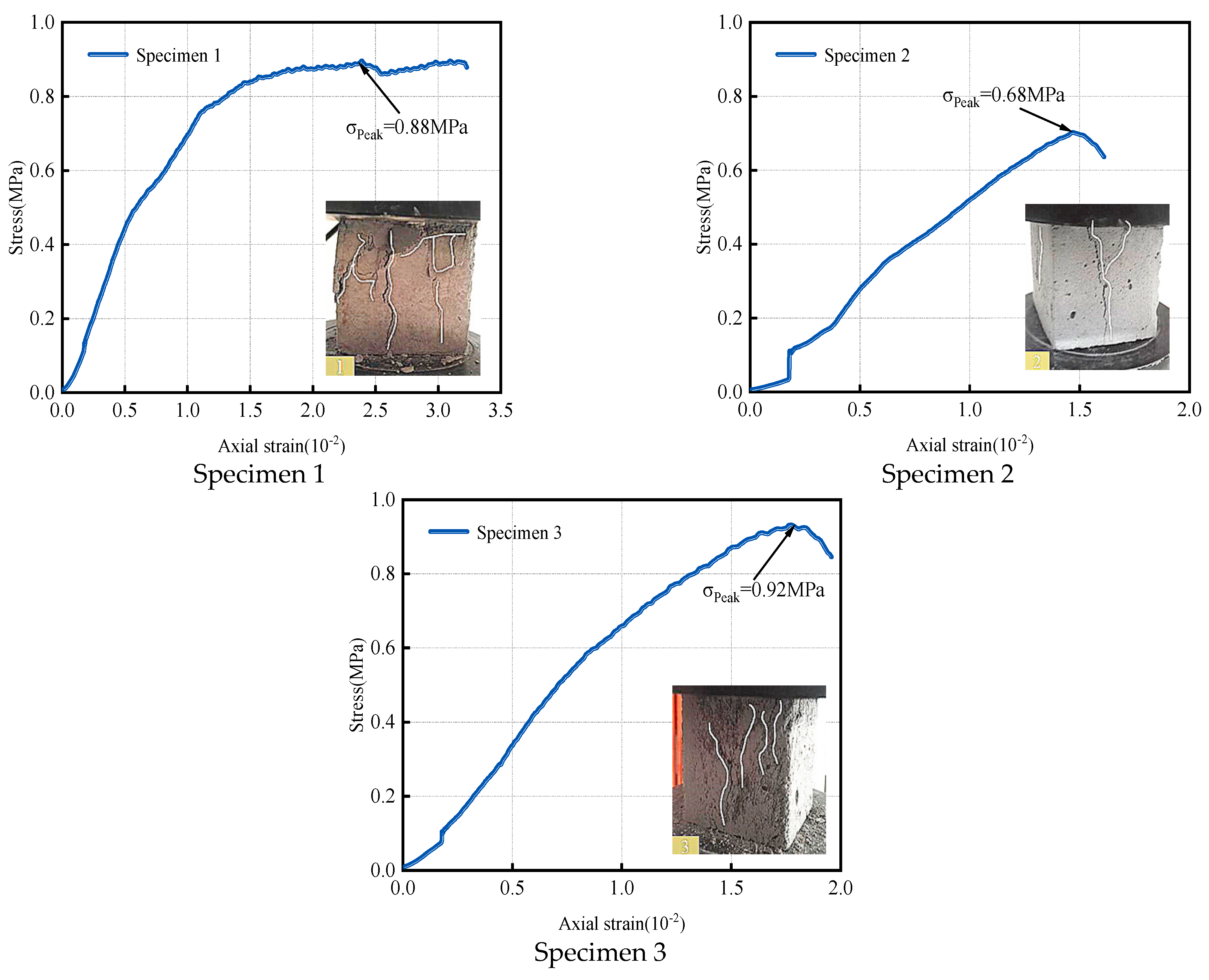
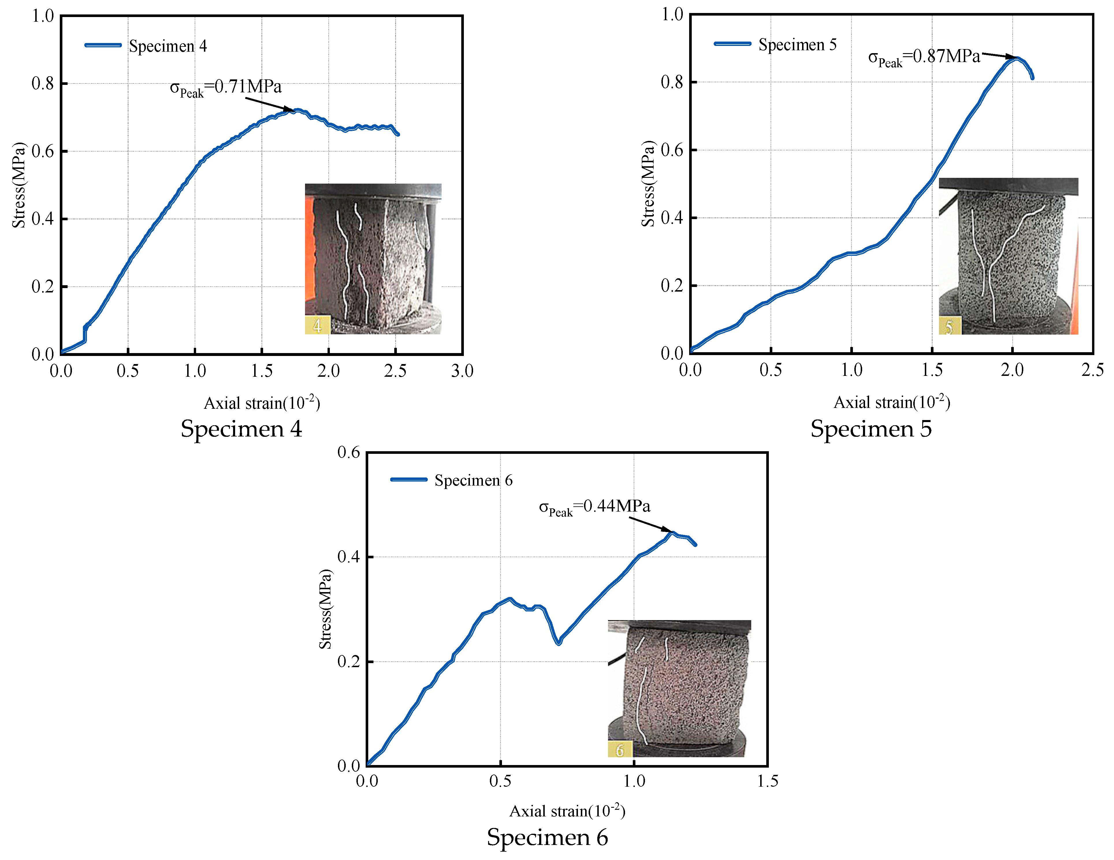
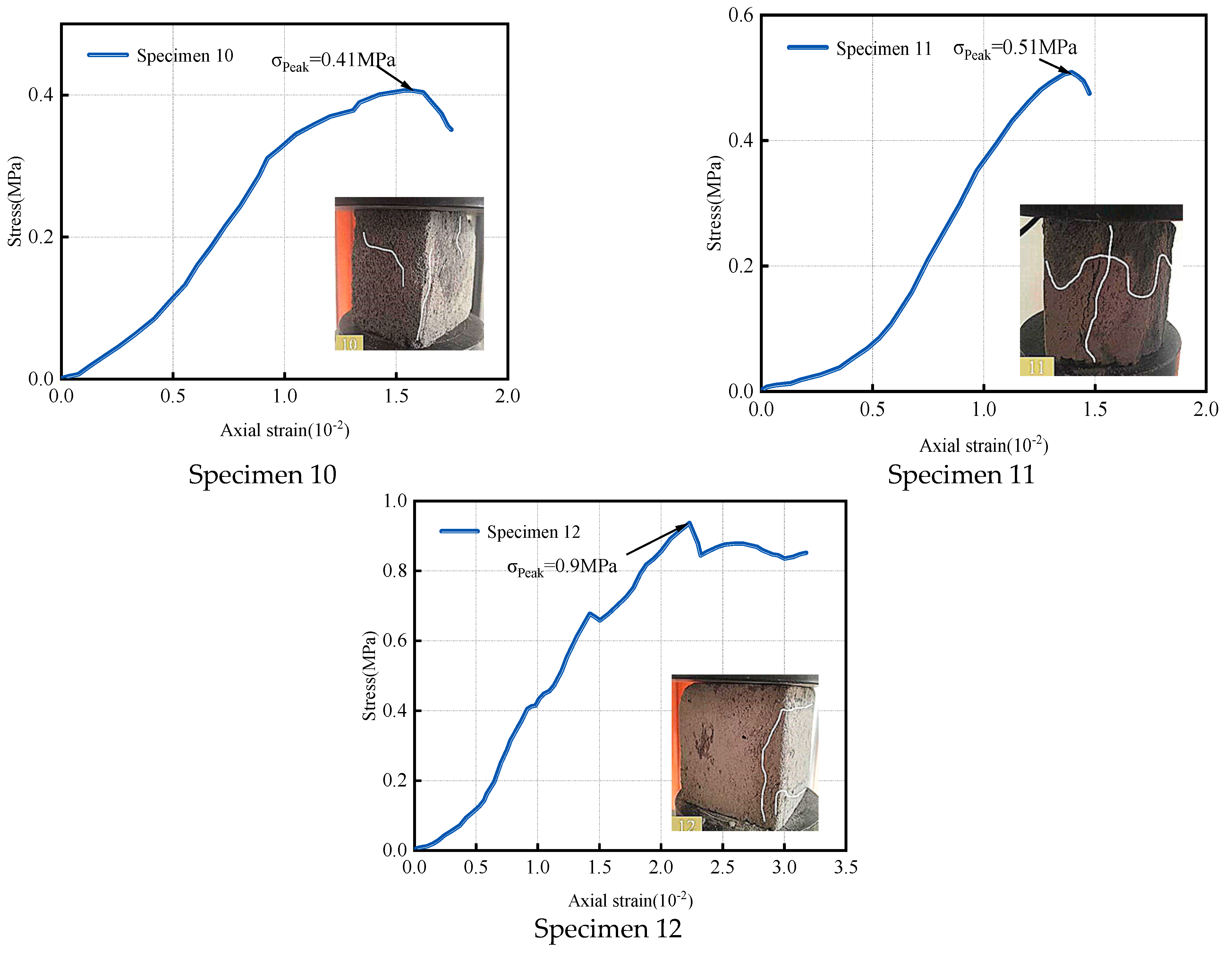
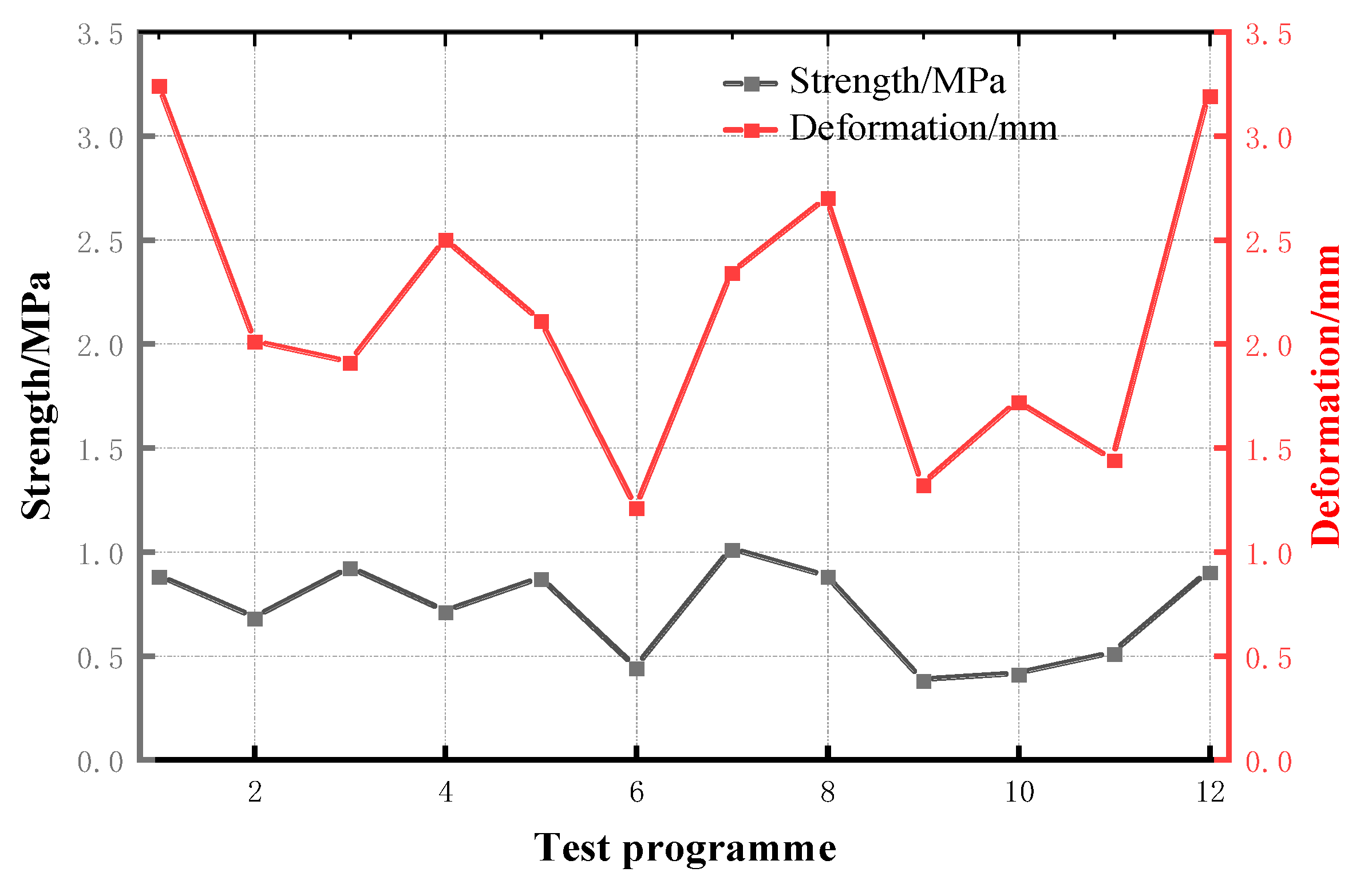
| Group Number | Program | Contact Area/cm2 | Peak Force/KN | Peak Compressive Strength/MPa | Deformation/mm |
|---|---|---|---|---|---|
| Group 1 | Programme 1 | 30 | 2.64 | 0.88 | 3.24 |
| Programme 2 | 30 | 2.04 | 0.68 | 2.01 | |
| Programme 3 | 34 | 3.14 | 0.92 | 1.91 | |
| Group 2 | Programme 4 | 42 | 3.01 | 0.71 | 2.50 |
| Programme 5 | 32 | 2.78 | 0.87 | 2.11 | |
| Programme 6 | 30 | 1.32 | 0.44 | 1.21 | |
| Group 3 | Programme 7 | 36 | 3.66 | 1.01 | 2.34 |
| Programme 8 | 30 | 2.64 | 0.88 | 2.70 | |
| Programme 9 | 30 | 1.13 | 0.38 | 1.32 | |
| Group 4 | Programme10 | 30 | 1.23 | 0.41 | 1.72 |
| Programme11 | 30 | 1.54 | 0.51 | 1.44 | |
| Programme12 | 40 | 3.60 | 0.90 | 3.19 |
| Hydraulic Support Number | Initial Pressure Appearance Distance/m | Cycle to Pressure Distance/m | Average Cycle to Pressure Distance/m | |||
|---|---|---|---|---|---|---|
| 1 | 2 | 3 | 4 | |||
| 1# | 18 | 10 | 8 | 10 | 12 | 10 |
| 2# | 16 | 8 | 12 | 12 | 12 | 11 |
Disclaimer/Publisher’s Note: The statements, opinions and data contained in all publications are solely those of the individual author(s) and contributor(s) and not of MDPI and/or the editor(s). MDPI and/or the editor(s) disclaim responsibility for any injury to people or property resulting from any ideas, methods, instructions or products referred to in the content. |
© 2024 by the authors. Licensee MDPI, Basel, Switzerland. This article is an open access article distributed under the terms and conditions of the Creative Commons Attribution (CC BY) license (https://creativecommons.org/licenses/by/4.0/).
Share and Cite
Sun, L.; Li, C.; Xu, Z.; Tai, L.; Cao, Y. Research on Mechanical Properties and Engineering Applications of Inorganic Cementitious Filling Materials in Coal Mine Abandoned Roadways. Appl. Sci. 2024, 14, 4826. https://doi.org/10.3390/app14114826
Sun L, Li C, Xu Z, Tai L, Cao Y. Research on Mechanical Properties and Engineering Applications of Inorganic Cementitious Filling Materials in Coal Mine Abandoned Roadways. Applied Sciences. 2024; 14(11):4826. https://doi.org/10.3390/app14114826
Chicago/Turabian StyleSun, Lei, Chong Li, Zhijun Xu, Lianhai Tai, and Yue Cao. 2024. "Research on Mechanical Properties and Engineering Applications of Inorganic Cementitious Filling Materials in Coal Mine Abandoned Roadways" Applied Sciences 14, no. 11: 4826. https://doi.org/10.3390/app14114826
APA StyleSun, L., Li, C., Xu, Z., Tai, L., & Cao, Y. (2024). Research on Mechanical Properties and Engineering Applications of Inorganic Cementitious Filling Materials in Coal Mine Abandoned Roadways. Applied Sciences, 14(11), 4826. https://doi.org/10.3390/app14114826