Article

Noise Analysis and Structural Optimization of Automobile Scroll Compressor Air Valve

1
School of Automotive & Rail Transit, Nanjing Institute of Technology, Nanjing 211167, China
2
College of Civil Aviation, Nanjing University of Aeronautics and Astronautics, Nanjing 211106, China
*
Author to whom correspondence should be addressed.
Appl. Sci. 2024, 14(11), 4875; https://doi.org/10.3390/app14114875
Submission received: 22 April 2024 / Revised: 27 May 2024 / Accepted: 3 June 2024 / Published: 4 June 2024

Abstract

:
The air conditioning compressor is a critical component in automobile heating, ventilation and air conditioning systems. However, compressor noise has long been a problem for automobile manufacturers. In recent years, the development and application of automobile air conditioning scroll compressors has increased significantly due to their low mechanical vibration and noise. However, their limitations in terms of airflow pulse and noise cannot be ignored, especially in low speed and high load conditions where the noise generated has a negative impact on driving and passenger experience. Noise and airflow pulses are important considerations that cannot be ignored. This study innovatively modifies the end cap structure of the scroll compressor, using the principles of expansion muffler and insertion tube structure, with the aim of improving the acoustic quality of the scroll compressor. The results show that the novel valve construction can significantly reduce the sound pressure level of the scroll compressor noise to a maximum of 75.20 dBA. The results of this study provide a theoretical basis and practical technical applications for future research and development in the automobile industry.

1. Introduction

The primary function of the automobile air conditioning system is to regulate the indoor temperature to optimize a comfortable and efficient driving experience. The air conditioning compressor, as a vital component of this system, plays a pivotal role in this process. Compressor noise commonly observed during operation includes pneumatic noise, vibration noise, and electromagnetic noise [1]. When the air conditioner is activated, the valve switch is closed to ensure uniform discharge of compressed gas. However, when the gas is discharged at high speed and pressure, it impinges on the static wall structure, inducing airflow regeneration noise, a phenomenon commonly referred to as pneumatic noise [2]. Aerodynamic noise, on the other hand, is generated by uneven internal fluid flow velocity or pulsation of fluid surface pressure, which significantly impairs driving and riding comfort. Noise, Vibration, and Harshness (NVH) has emerged as a key indicator of in-vehicle comfort, with increasing emphasis placed on this aspect by private car owners and car manufacturers in recent years [3]. Therefore, the management and control of compressor aerodynamic noise has become a key focus of this study.
At present, most air conditioning noise management strategies focus on the design and modification of compressor structure. In their studies, Galindo et al. successfully reduced vibration noise and aerodynamic noise in the 50–1600 Hz frequency range through modifications to this component [4]. Similarly, Shen et al. reduced the operating noise of a twin screw compressor by establishing end face attenuation channels and increasing Helmholtz resonators in the exhaust pipe. Simulation and experimental results show that the mean noise reduction values achieved are in the range of 5.0 dBA–10.0 dBA [5]. Some researchers have also focused on modifying or enhancing the muffler structure to reduce noise levels. For example, Ji et al. identified the noise source as exhaust noise and improved the original exhaust channel structure by using three parallel muffler chambers to connect to the air conditioning pipeline, resulting in a 9.5 kPa reduction in airflow pulsation and a nearly 6 dBA reduction in sound pressure level [6]. Wu et al. identified the noise source based on near-field noise measurements and reduced the sound pressure level by 4.1 dBA by proposing a noise control method coupled with structural optimization and perforated mufflers [7]. Sun et al. improved the structure of the air conditioning compressor anechoic enclosure through a combination of experiment and simulation, thus achieving the effect of reducing the sound pressure level [8]. Han et al. analyzed the noise spectrum and found that mid- and high-frequency attenuation needs to be improved. They modified the original air filtration muffler structure by increasing the flow regulator box and replacing the internal filler material with aluminum silicate rock wool. In addition, a resistive muffler mechanism was connected in parallel with the original structure to mitigate wideband noise. These two integrated air filtration mufflers reduced sound pressure levels by 23.6 dBA and 24.6 dBA, solving the above problems [9]. Zhang et al. innovated on the traditional, poorly sealed muffler by designing a muffler that could be partially snapped together at the top and bottom. This new muffler design, including an upper and lower cover snapped together, significantly reduced the chamber leak problem. The innovative muffler structure not only reduced the sound pressure level by 1.87 dBA but also increased the cooling capacity by 7.4 W [10]. Chen et al. proposed an innovative system that uses an amphibian waveguide and two quarter wavelength tubes (QWTs) with different cross-sectional sizes. When sound waves enter the narrow tube, they are effectively absorbed by the spacing between the tubes, achieving noise absorption of 5.2 dBA in a frequency range of 6400 Hz. Notably, the high frequency resonance effect of the system is noticeable from 1800 Hz to 6400 Hz, making it an effective noise reduction solution [11]. Dianov avoided vibration and noise caused by reversing reciprocating compressor pistons during shutdown by modifying the motor algorithm [12]. Zhang et al. successfully reduced the noise of an air-conditioning compressor by correctly setting the appropriate centrifuge clearance, motor air clearance, and coil length [13]. The study conducted by He et al. shed light on the noise control technology of screw refrigeration compressors, highlighting the problems associated with gas pulsation and the serious vibrations and noise it generates. Through their extensive research, they tested various techniques such as acoustic wave interference, gas–solid resonance, and porous mufflers. Their efforts culminated in the optimization of a single two-stage screw refrigerant compressor for noise mitigation purposes. Experiments have shown that noise is effectively mitigated by these strategic optimization interventions in a variety of operational scenarios. This research provides crucial insights for rectifying the noise problem of screw refrigeration compressors [14]. Ebrahimi-Nejad et al. conducted an in-depth study of muffler baffle configurations, dimensions, chamber volume, and inlet–outlet positions. Through his comprehensive review, he determined that a circular baffle offers a wide bandwidth range with a transmission loss of 58 dBA. In addition, he found that about 75% of rectangular plate baffles exhibit a 67 dBA transmission loss. This led to the conclusion that a dual chamber muffler has a wider bandwidth range and a higher transmission loss than a single chamber muffler [15]. An expansion muffler is a specific type of resistance muffler that relies on the principle of sudden cross-section expansion or contraction. This causes a significant change in the acoustic impedance of the muffler pipeline, thus impeding certain frequency sound waves from passing through the pipeline. These sound waves are then reflected back to the noise source, while other sound waves traveling in different directions of the same frequency are offset to each other, allowing the muffling function to be achieved [16].
This research focuses on improving the internal architecture of the automobile scroll compressor without changing the external dimensions of the valve. Simulation analysis is carried out under real-world operating conditions to ensure the effectiveness of the project’s ultimate goal—reducing the sound pressure level and sound power of the automobile scroll compressor.

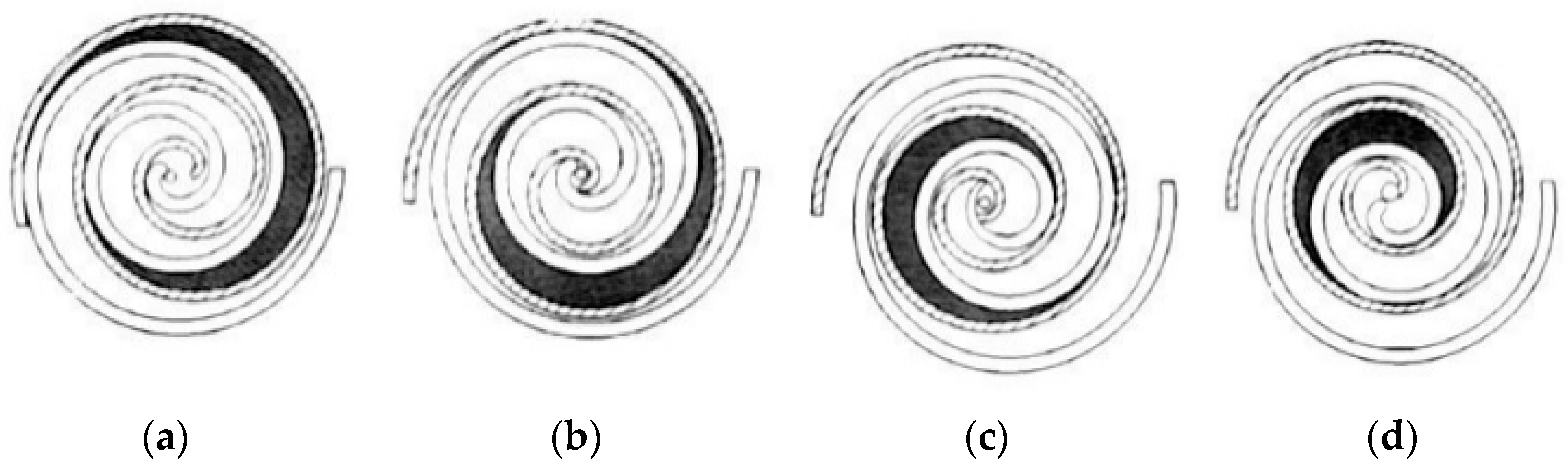
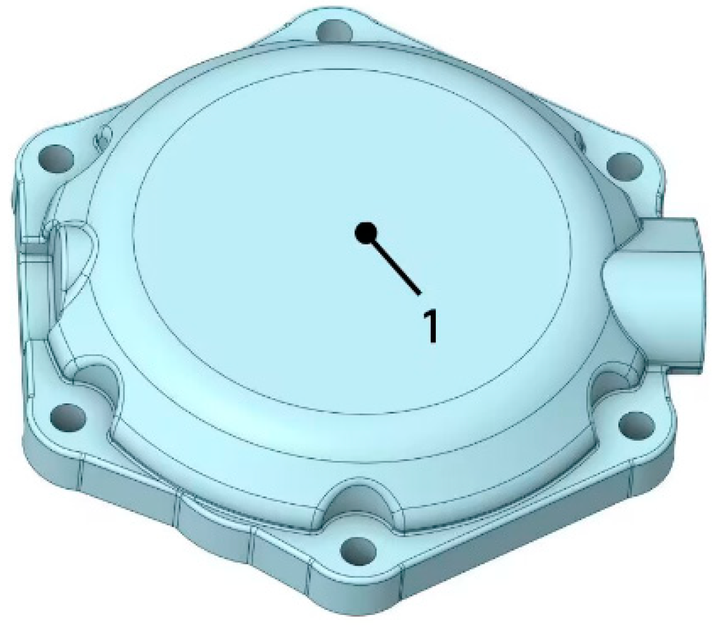
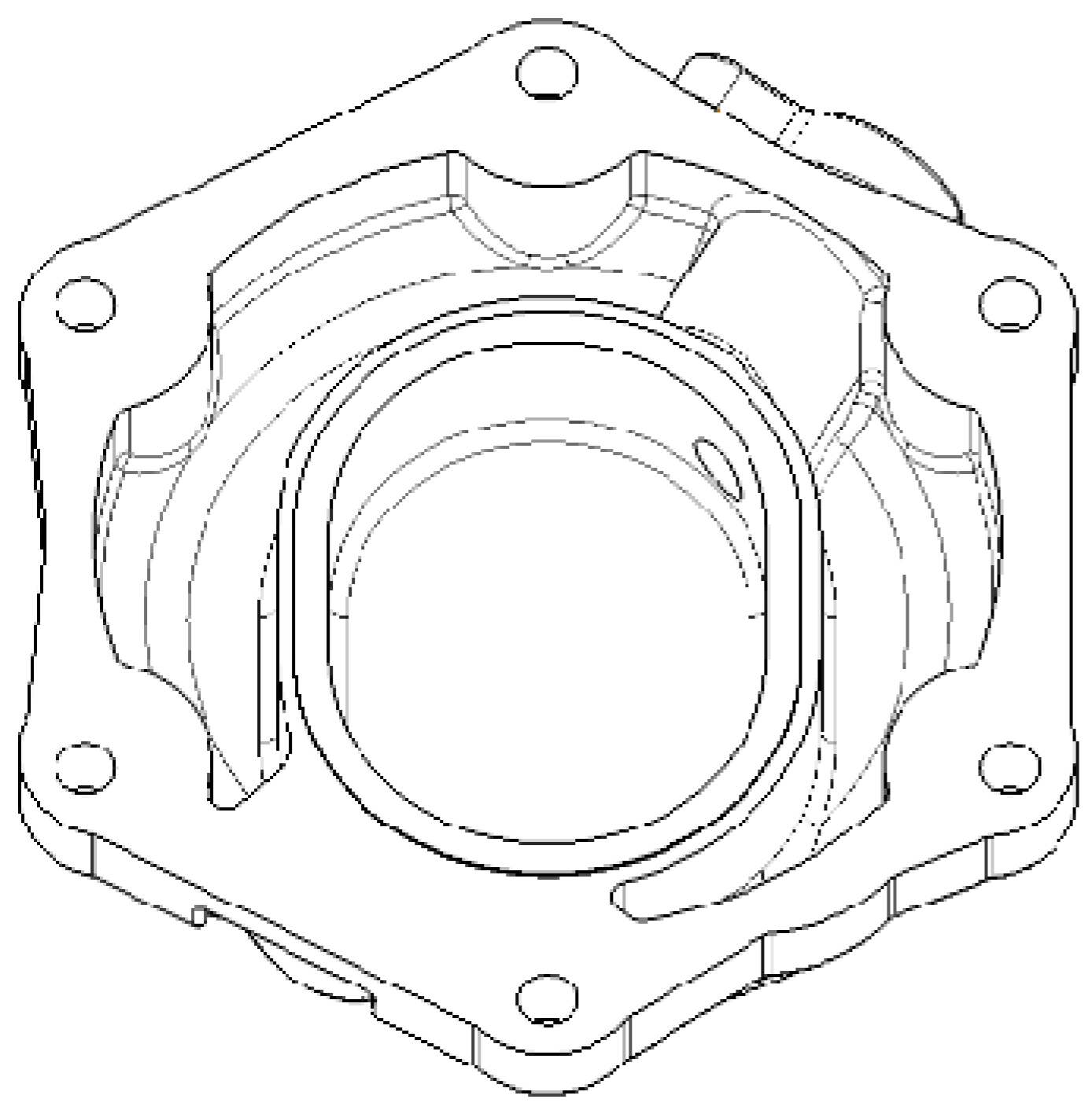
2. Scroll Compressors and Valves

The valve exhibits the compressor’s superior sealing capacity due to its inherent resilience and the external pressure acting on it. When the pressure in the central chamber exceeds the sum of the external pressure and its own resistance, the valve disc opens to allow compressed gas to escape. The scroll compressor achieves gas compression through the interconnection of a dynamic and static scroll disk as depicted in Figure 1. The dynamic scroll disk rotates around the static scroll disk at a specific angle, referred to as the crankshaft angle, symbolized by θ = 0°. The suction chamber exhibits its maximum volume during the crankshaft angle increase, with the volume of the suction chamber initially increasing and subsequently decreasing until the crankshaft angle reaches 90°. Upon completion of the suction phase, the suction chamber has been completely transformed into a compression chamber. As the crankshaft angle increases from θ = 90° to θ = 180°, the effective volume of the compression chamber consistently decreases and gradually converges towards the center of the dynamic and static vortex discs, ensuring that the compression chamber remains in a closed state. The dynamic and static scroll disk continue to engage, with the crankshaft angle θ increasing from 180° to 270°. This transition results in the compression chamber being transformed into the exhaust chamber. During the crankshaft angle increase from 270° to 360°, the compression chamber is completely transformed into the exhaust chamber, and the working volume gradually reduces. When the crankshaft angle reaches 360°, the scroll compressor completes its work cycle.

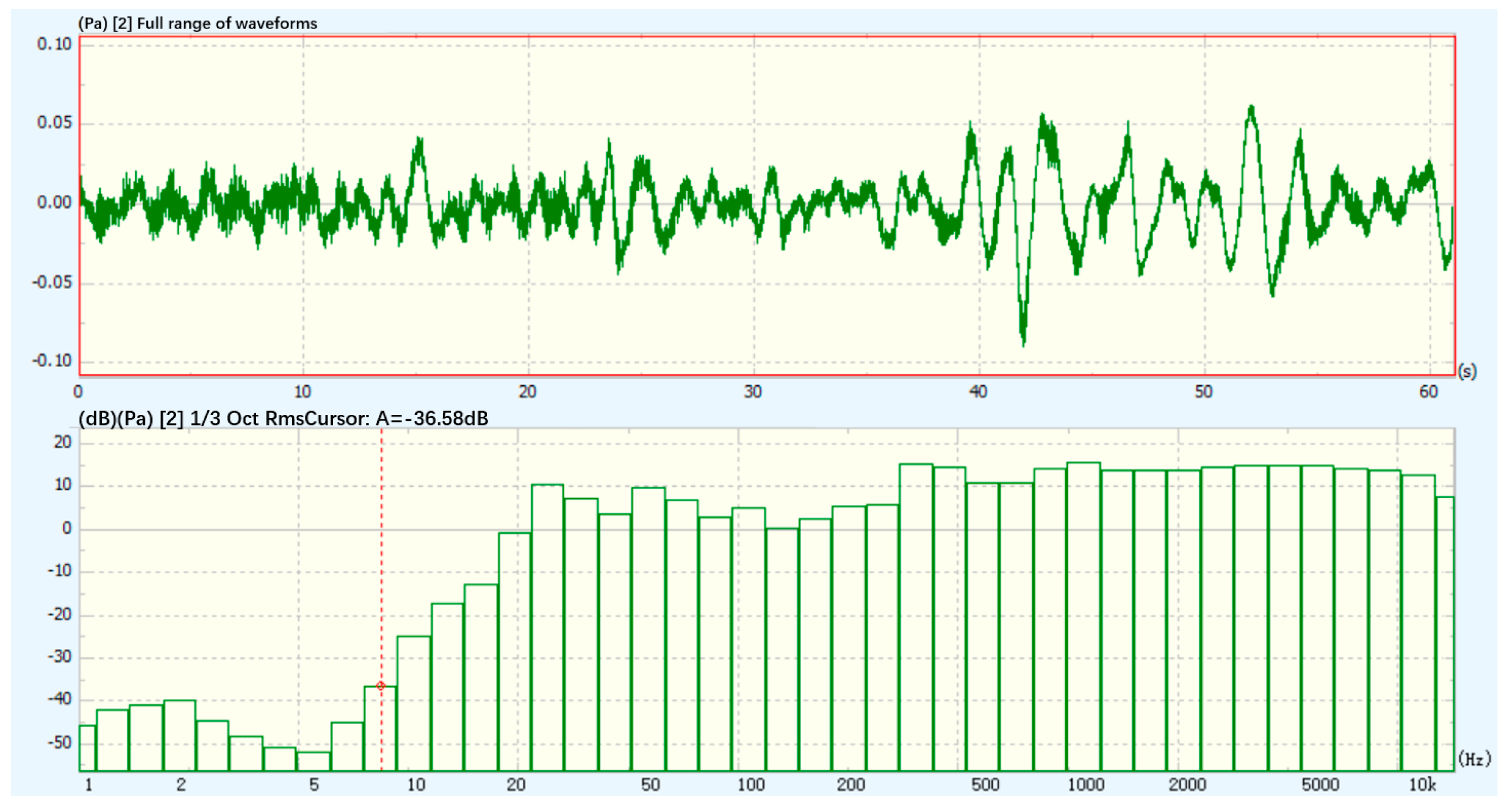
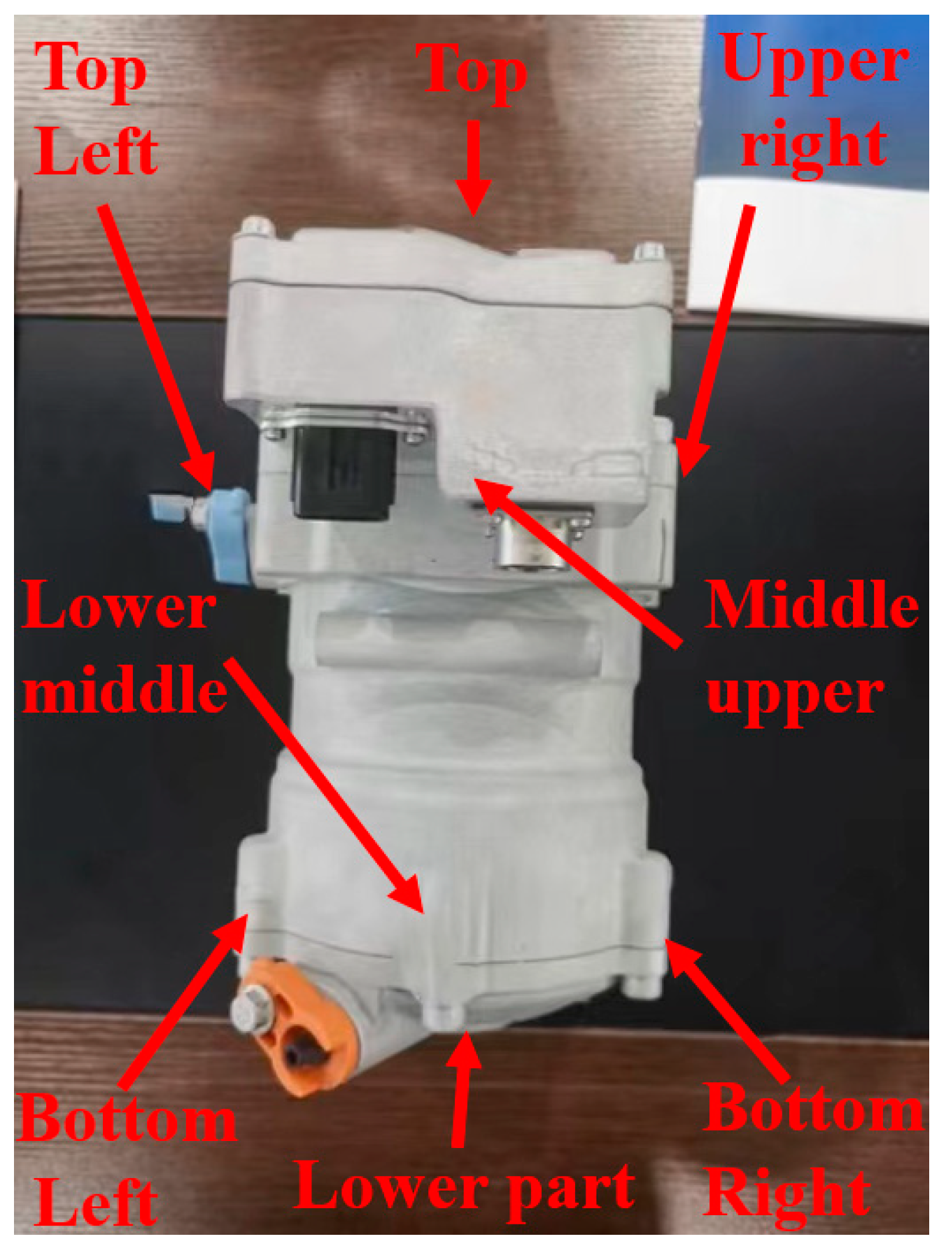
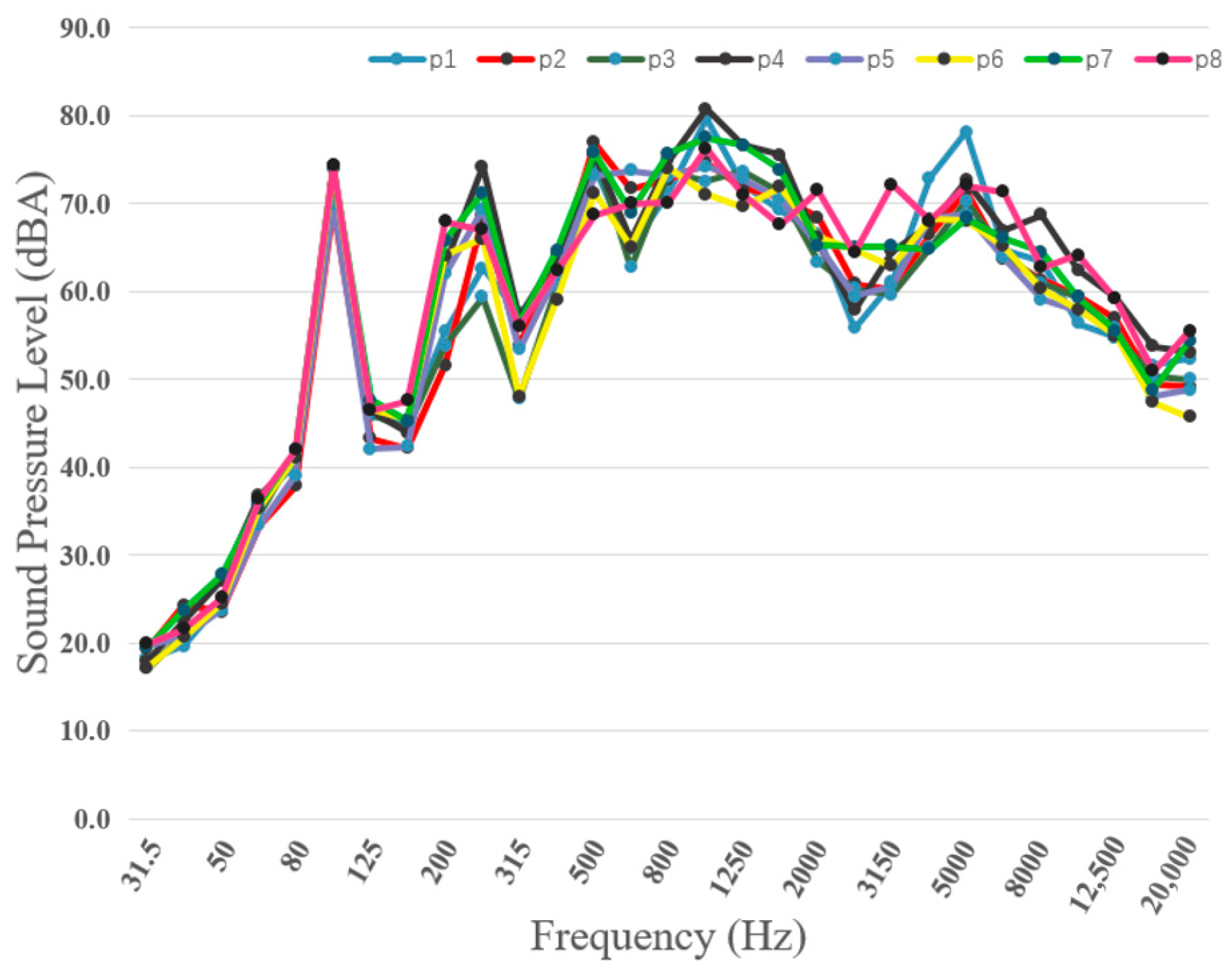
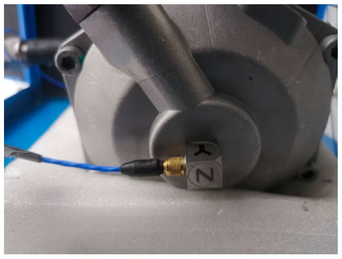
3. Bench Test Analysis

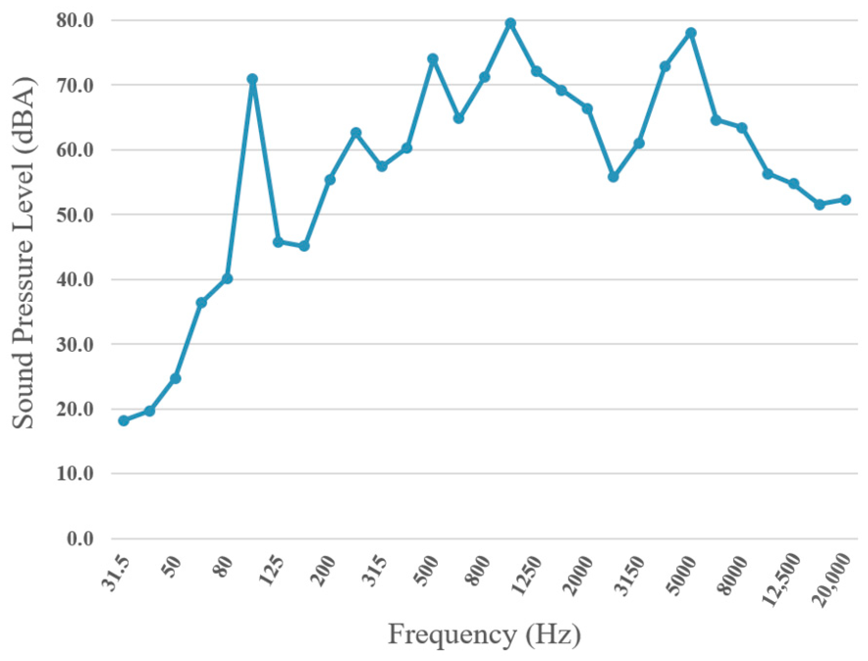
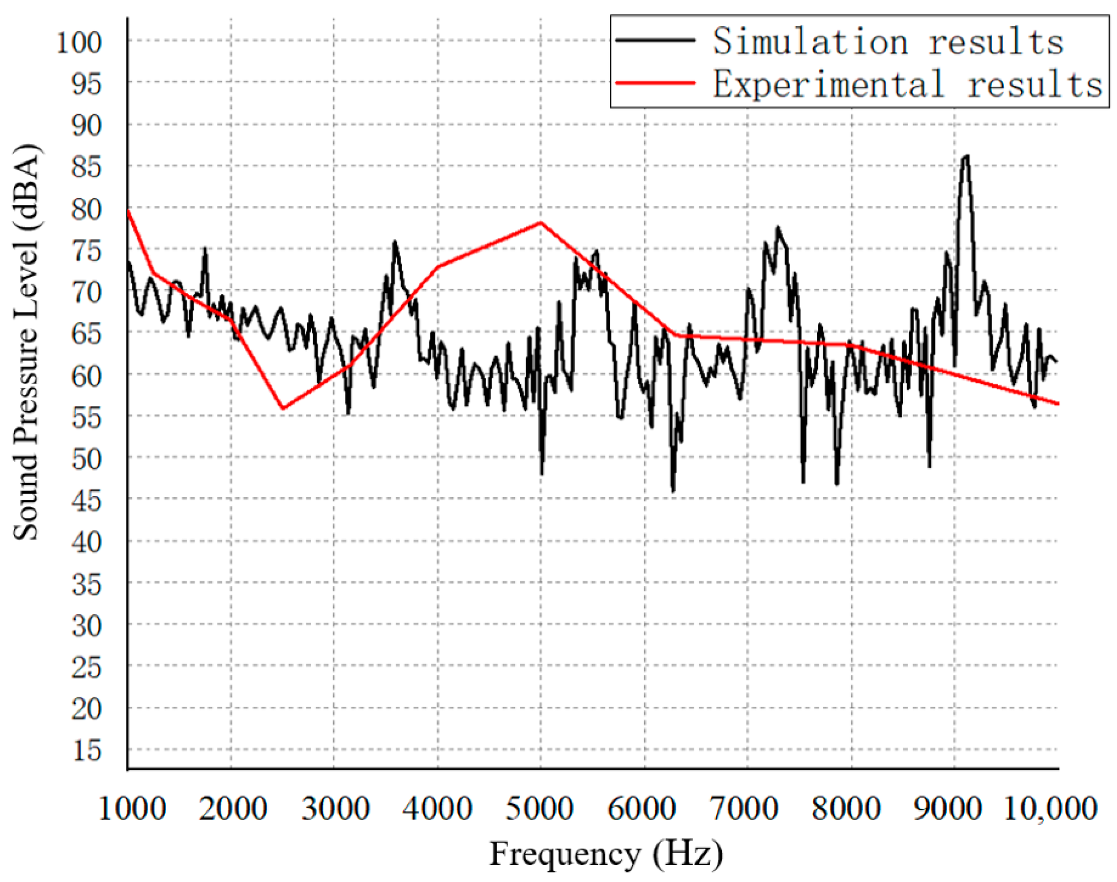
3.1. Analysis of Experimental Results

In accordance with the Chinese National Standard GB/T 4980-2003 compressor test conditions and test methods [17], the stable performance of the compressor in the semi-anechoic chamber environment to the rated operating conditions, the test equipment, including a 12-channel data collector, a microphone, data analysis computer, Simcenter Testlab 2306 data analysis software, semi-anechoic chamber of the whole waveform and noise spectrum of the noise floor is shown in Figure 2, and the test position is shown in Figure 3. First of all, we need to determine the compressor noise radiation location characteristics, using the compressor near-field noise test, and through a spectrum comparison, we determine the location of the high-frequency noise radiation, the microphone and the compressor shell surface distance of 50 mm. A comparison of the spectrum found that the lower end of the compressor noise observation point is the most prominent (as shown in Figure 4) to determine that the lower end of the compressor is the main radiation surface of the noise. The position of the lower end of the compressor is shown in Figure 5, and the spectrum of the lower end is shown in Figure 6.
Figure 6 shows a spectral analysis of the sound pressure inside the compressor. It reveals a notable peak at low frequencies (30–150 Hz) with a sound pressure level of 71 dBA. This peak decreases gradually as the frequency increases. The mid-frequency band (500–5000 Hz) shows fluctuations, with the maximum sound pressure level of 79.6 dBA recorded at 1000 Hz. Subsequently, the sound pressure level decreases gradually as the frequency increases. The sound pressure level at 2500 Hz is relatively low at 55.8 dBA, but gradually increases to a very high value of 78.1 dBA at 5000 Hz. In the high frequency band, the sound pressure level remains relatively stable, with no significant fluctuations. The sound pressure level decreases gradually as the frequency increases.

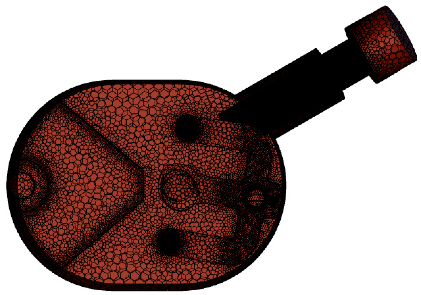
3.2. Analysis of Simulation Results

Figure 7 presents a simplified three-dimensional (3D) model derived from the software watershed and subsequently imported into Fluent’s meshing module for construction. The lattice was specified as a polyhedral mesh and encrypted to ensure the preservation of intricate details. The software used Space Claim 2023 R1 software to remove chamfers, truncated edges, and other features that have minimal impact on simulation results, yet significantly impact the simulation process.
To ensure the success of event simulation experiments, the following prerequisites are necessary:
(1)
The muffler medium used is non-viscous, thus avoiding any energy loss associated with the propagation of sound waves. Moreover, the heat transfer between the wall and the external environment is not factored into the analysis.
(2)
The initial speed of the refrigerant is initially set to zero at the start of operation to ensure zero interference to the system. This positioning allows the static density and pressure of the refrigerant to accurately align with the actual operating conditions.
(3)
Each acoustic parameter of the sound wave is a first-order trace of the propagation process, and the propagation itself is devoid of heat transfer.
In order to assess acoustic noise, a designated point known as “point 1” has been established, and its corresponding coordinates are shown in Figure 8. A visual depiction of the comparison between computational results and empirical data are further illustrated in Figure 9.
A comparison of empirical observations with computational simulations indicates that similar trends exist within the frequency bandwidth of 10,000 Hz. Before 2500 Hz, an increase in frequency is accompanied by a decrease in sound pressure at the receiving point 1. From 2500 Hz to 5000 Hz, SPL increases with frequency, and from 5000 Hz to 10,000 Hz, SPL is inversely proportional to frequency. As the sound insulation effect of the solid part of the cylinder head on the noise and vibration caused by airflow pulsation affects the SPL noise, there is some discrepancy between the simulation results and the experimental results. However, the divergence is within 10%, which is considered acceptable, and the simulation results maintain a degree of credibility.

4. Muffler Acoustic Calculation Model

4.1. Theoretical Studies

The propagation of acoustic waves in a homogeneous, non-viscous medium is described by the Helmholtz Equation (1) [18]:
{ 2 P + k 2 P = 0 k = ω c
where 2 denotes the Laplace operator, k denotes the wave number, ω denotes the angular frequency, and c and P denote the sound velocity and sound pressure, respectively. The solution for the region yields its sound pressure.
The physical structure of the tube and chamber has been precisely delineated in Figure 10, and the acoustic specifications are as follows:
Δ L = 10 lg [ 1 + 1 4 ( S 1 S 2 S 2 S 1 ) 2 sin 2 ( k L ) ]
In Equation (2), L represents the amount of noise elimination achieved by the expansion chamber, the variables S 1 and S 2 represent indicate the cross-sectional surface area of the expansion chamber, as well as the cross-sectional surface area at the inlet and outlet zone, respectively, L represents the length of the expansion chamber, and k is the wave number.
The expression for the expansion ratio m of a resistant muffler is defined as follows:
m = S 2 / S 1
The maximum level of silencing performance is achieved when the sine function reaches its maximum value of 1, resulting in superior noise elimination as follows:
Δ L max = 10 lg [ 1 + 1 4 ( m 1 / m ) 2 ]
And Equation (5) is as follows:
k L = ( 2 n 1 ) π / 2
Equation (6) provides a method for calculating the band-in frequency:
k = 2 π f / c
At this point, the silencing frequency of the corresponding muffler is as follows:
f max = 2 n + 1 4 c L
When the sinusoidal function attains a minimum value of 0, the muffler ceases to perform its muffler function and the sound wave, thus traversing the expansion section unattenuated. The corresponding frequency at this point is the passing frequency, the expression of which is as follows:
f min = n 2 c L
By utilizing Equations (7) and (8), the corresponding frequency range of the expansion muffler can be calculated as follows:
n 2 c L f 2 n + 1 4 · c L , n = 0 , 1 , 2 ,
It is evident that the length of the expansion chamber L is a multiple of an odd number corresponding to the given frequency 1/4 wavelength.
According to the established plane wave theory, the appropriate calculation frequency for noise reduction can be determined.
f c = 1.8 c π d 0
Furthermore, it is clear from Equation (2) that regardless of whether the pipe section is dilated or constricted, so long as the dilation ratio, m, remains identical, the effectiveness of noise mitigation throughout the structure will remain the same, with the primary determinant of the predominant frequency of noise reduction being the L dimension of the expansion muffler.

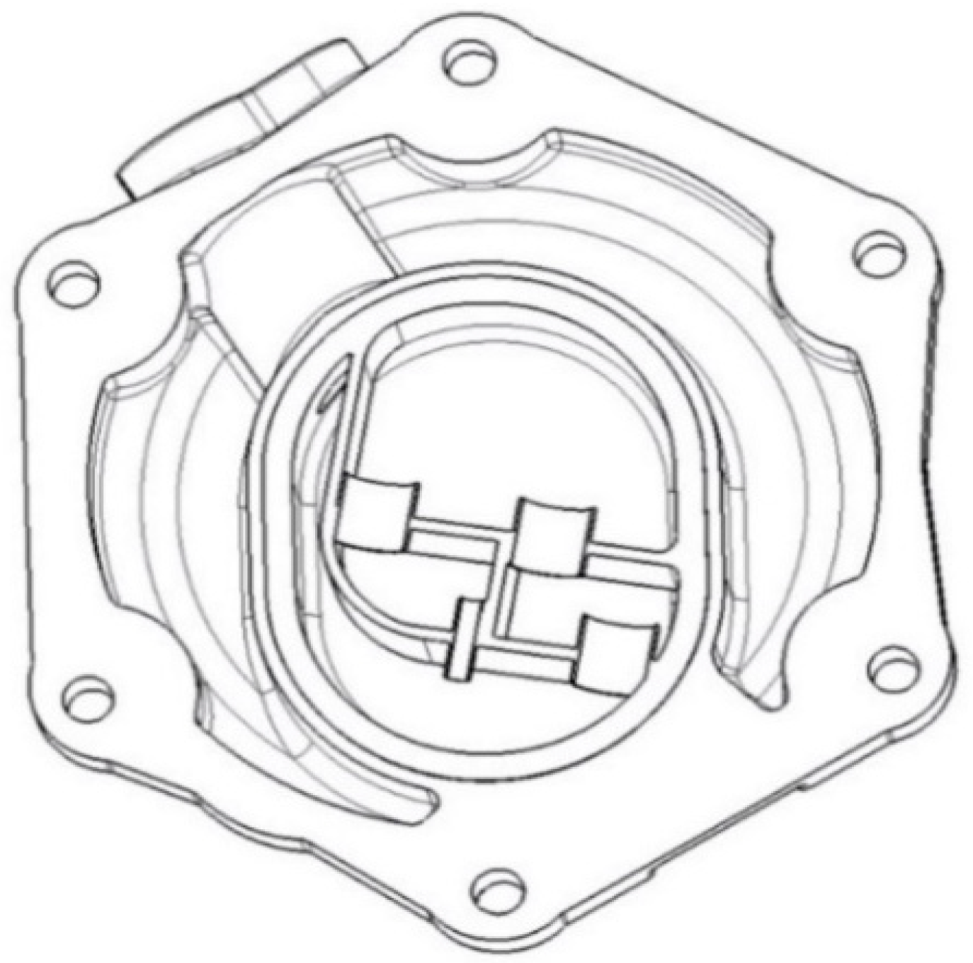
4.2. Structural Innovation Design

After a simulation analysis of the original scroll compressor gas valve configuration, the findings depicted in Figure 11 suggest that the surface sound power level at the rear end of the valve chamber is relatively low, while the surface sound power level at the front end is relatively elevated. This observation indicates that the sound wave is not adequately reflected upon entering the chamber, necessitating the redesign of the valve chamber structure to enhance its utilization and ultimately achieve the objective of reducing aerodynamic noise.
Figure 12 provides a schematic representation of the compressor end cap, which shows that the internal cavity housing the valve plate possesses a significant volume, resulting in a relatively low space utilization rate. This configuration possesses limited noise-dampening capabilities. On the contrary, Figure 13 illustrates the structural principle of the expansion muffler, which serves as the basis for the regional schematic. The design not only fulfills its primary function but also divides the cavity into four distinct chambers, with chambers 1 and 2 connected in series, and chambers 3 and the valve blade chamber operating in parallel.
The revised end cap schematic shown in Figure 14 reflects the implementation of chamber walls with a thickness of 1.5 mm following chamber division. These walls are carefully crafted by welding of a partition plate, thus ensuring the necessary internal structural integrity for the compressor, while at the same time contributing to noise reduction.

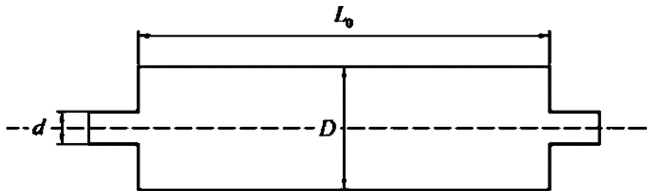
4.3. Parameter Design

After detailed analysis, it can be observed that the expansion ratio directly influences the muffler volume, while the length of the muffler chamber serves to establish the muffler structure’s muffler frequency. In line with engineering practice, it is apparent that the expansion ratio exhibits a value range of 5 < m < 20, with a general preference for 9 < m < 16 [19]. In the context of the current model, the cross-sectional area of the muffler chamber expansion chamber is 373 mm2. To order to ensure that the expansion ratio m falls within the scope of engineering reality, the cross-sectional area of the entrance is adjusted to 36 mm2, thus ensuring the muffler chamber’s muffling volume.

5. Verification of Sound Field Simulation Results

A scroll compressor air valve was selected as the research object to perform 3D modeling and flow channel extraction of both the unmodified chamber end cap and the modified chamber end cap. The wall and internal flow fields were carefully meshed to facilitate precise acoustic analysis. The sound pressure level at the end cap was determined using the FW-H acoustic calculation model. Table 1 shows the material parameters of the air valve, while Table 2 shows the working environment of the air valve.

5.1. Working Conditions

In this simulation, the maximum magnitude of pneumatic noise is observed when the valve is fully actuated, indicating rapid gas velocity, significant volumetric flow rate, and substantial sonic pressure amplitude in subsequent pneumatic noise.

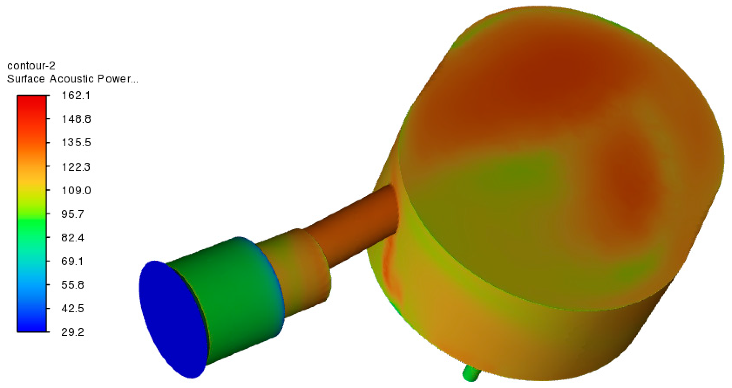
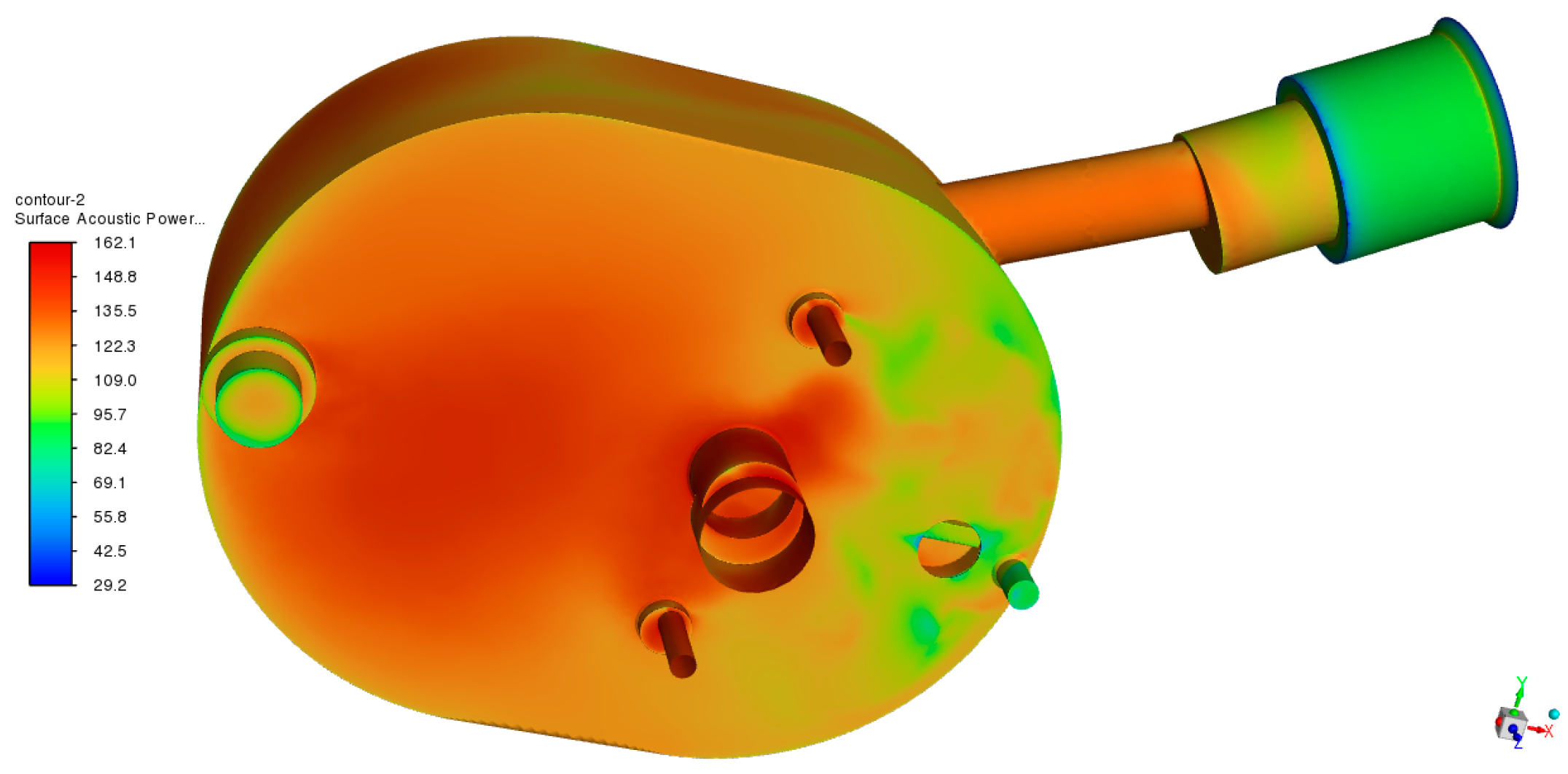
5.2. Comparison of Surface Sound Power Levels

Surface sound power refers to the energy distribution of sonic energy generated by surface fluid flow, which is fundamentally related to eddy currents, turbulence, and other fluid movements. This metric serves as a critical indicator for assessing the noise pollution from fluid flow.
The comparative analysis in Figure 15 and Figure 16 shows the internal flow field simulations for the unmodified end cap and the one with a split chamber. A significant reduction of 17 dB in the maximum surface acoustic power level is observed for the chambered end cap, indicating its effectiveness in noise reduction. This improvement is attributed to the design of the chamber, which facilitates wave reflection, absorption, and energy dissipation, resulting in a more uniform distribution of acoustic power. When the valve opens, sound waves enter the chamber through the exhaust port, and upon hitting the wall, they are reflected. These reflections create interference with the incoming sound wave. If the phase difference between the two is 180°, they cancel each other, contributing to noise reduction. The chamber division serves two purposes: it reduces the likelihood of sound waves reaching the exhaust directly, causing more waves to interact with the walls and dissipate energy (absorption). In addition, the longer path within the divided chambers further dissipates sound energy.

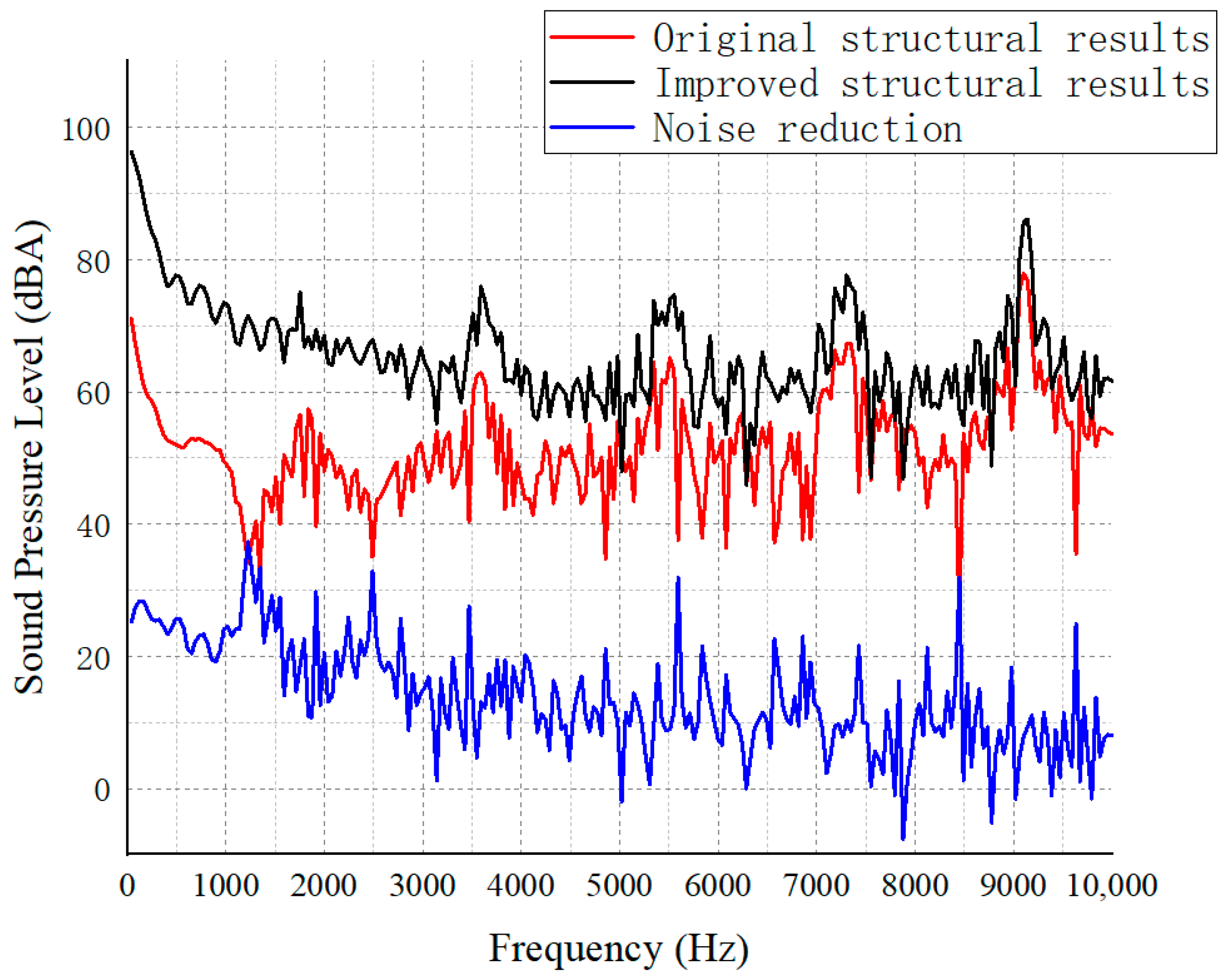
5.3. Sound Pressure Level Comparison

The level of sound pressure after structural modification is depicted in Figure 17, showing a comparison between the original structure and the structure after division of the chamber at acceptance point 1 in terms of noise level.
As shown in Figure 18, the amplitude of sound pressure at observation points 1 resonates with increasing frequency. Wave peaks appear at 1750 Hz, 3580 Hz, 5500 Hz, 7300 Hz, and 9000 Hz, respectively, in which the sound pressure level of the end cap of the undivided chamber shows the maximum value at 9000 Hz, which is about 86.10 dBA, and the overall trend of the sound pressure level of the end cap after dividing the chamber is the same as that of the end cap of the undivided chamber, and there are five wave peaks in both of them; however, the sound pressure level at observation point 1 increases with frequency, reaching 9000 Hz, which is about 78.93 dBA. However, the sound pressure level at observation point 1 increases with frequency, and the maximum value of about 78.93 dBA occurs at 9000 Hz. Compared with the sound pressure level at observation point 1 of the undivided structure, the overall performance of the sound pressure level of the end cap after dividing the chamber is improved. Therefore, according to the analysis results, we can obtain that the end cap with a chamber structure has a certain weakening effect on airflow pulsation and can reduce the sound pressure level at observation point 1, with a maximum value of 37.31 dBA.

5.4. Transfer Loss Analysis

In order to mitigate the impact of the enhanced structure on compressor pressure loss, the insertion tube structure is strategically incorporated at the inlet and outlet sites of the modified configuration. Specifically, muffler transmission loss is defined as the difference in sound power between the incident sound and the emitted sound, as illustrated in Equation (11).
δ TL = L w i L w t = 10 lg ( W i W t )
where δ T L denotes the transmission loss; w i denotes the incident sound power, i.e., the sound power at the entrance of the muffler structure; and w t is the transmitted sound power, i.e., the sound power at the exit of the muffler.
The improved structure is illustrated in Figure 18.
As demonstrated in Figure 19, the anechoic end cap configuration with the inserted pipe structure not only mitigates the pressure drop at the inlet and outlet points but also enhances the loss of noise transmission, thus facilitating further noise attenuation within this structure. In the frequency range of 0–3200 Hz, the noise transmission loss is directly proportional to the frequency, exhibiting a maximum value of 70.95 dBA and a minimum value of 6.3 dBA. Conversely, in the frequency range of 3200–6400 Hz, the noise transmission loss is inversely proportional to the frequency, attaining a minimum value of 27.75 dBA, with the noise elimination of the muffler with the inserted pipe structure reaching a maximum value of 6900 Hz. Beyond 6900 Hz, the noise transmission loss fluctuates with the increase in frequency, but the minimum value remains above the overall minimum value of 8.24 dBA.

6. Conclusions

This article comprehensively investigates and explores the root cause of abnormal noise in the valve section of an automobile scroll compressor and then uses the principle of resistive muffler to innovatively design a new structure that can effectively mitigate noise. The evaluation of the effectiveness of the new structure is based on the sound pressure level and sound power level, which are two important indicators that measure the noise level of the structure. The evaluation results reveal several key findings:
(1)
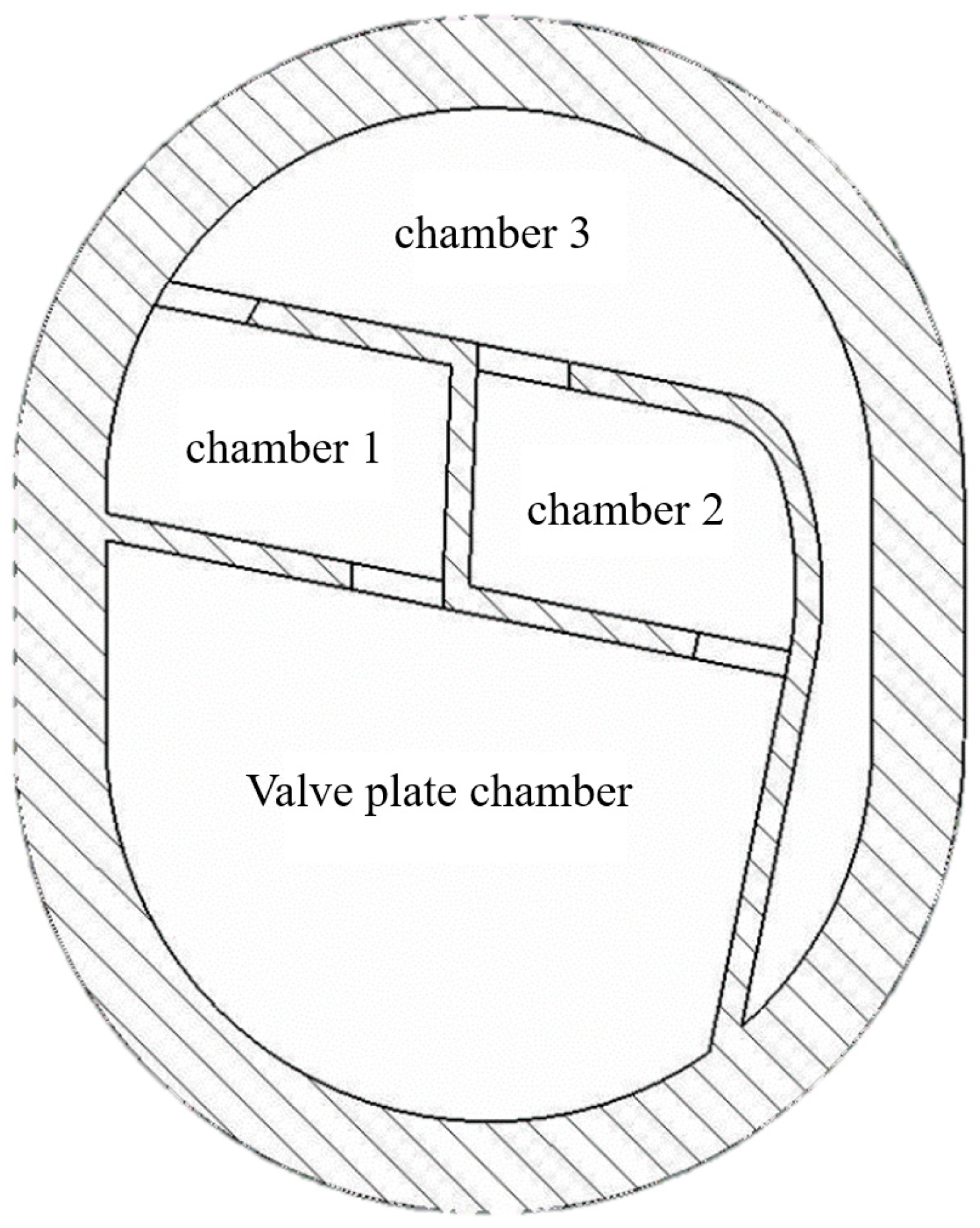
For the undivided muffler chamber, the sound power level of its rear muffler chamber is uneven, which means that the sound wave cannot fully reflect in extra space, resulting in low structural utilization.
(2)
The expansion ratio of the resistive muffler has a significant impact on the muffling volume of the structure, which means that the muffling volume will increase as the expansion ratio increases.
(3)
The surface sound power level of the divided chamber is more even, which means that the sound power level of the structure is more uniform, and the maximum value is reduced by 17 dBA compared to the undivided structure, indicating that the divided chamber structure can improve the muffling effect.
(4)
A comparison of the sound pressure levels before and after the end caps are divided reveals a decrease in sound pressure levels in all bands, with the maximum reduction being 37.31 dBA, which means that the new structure can effectively reduce the noise level of the structure.
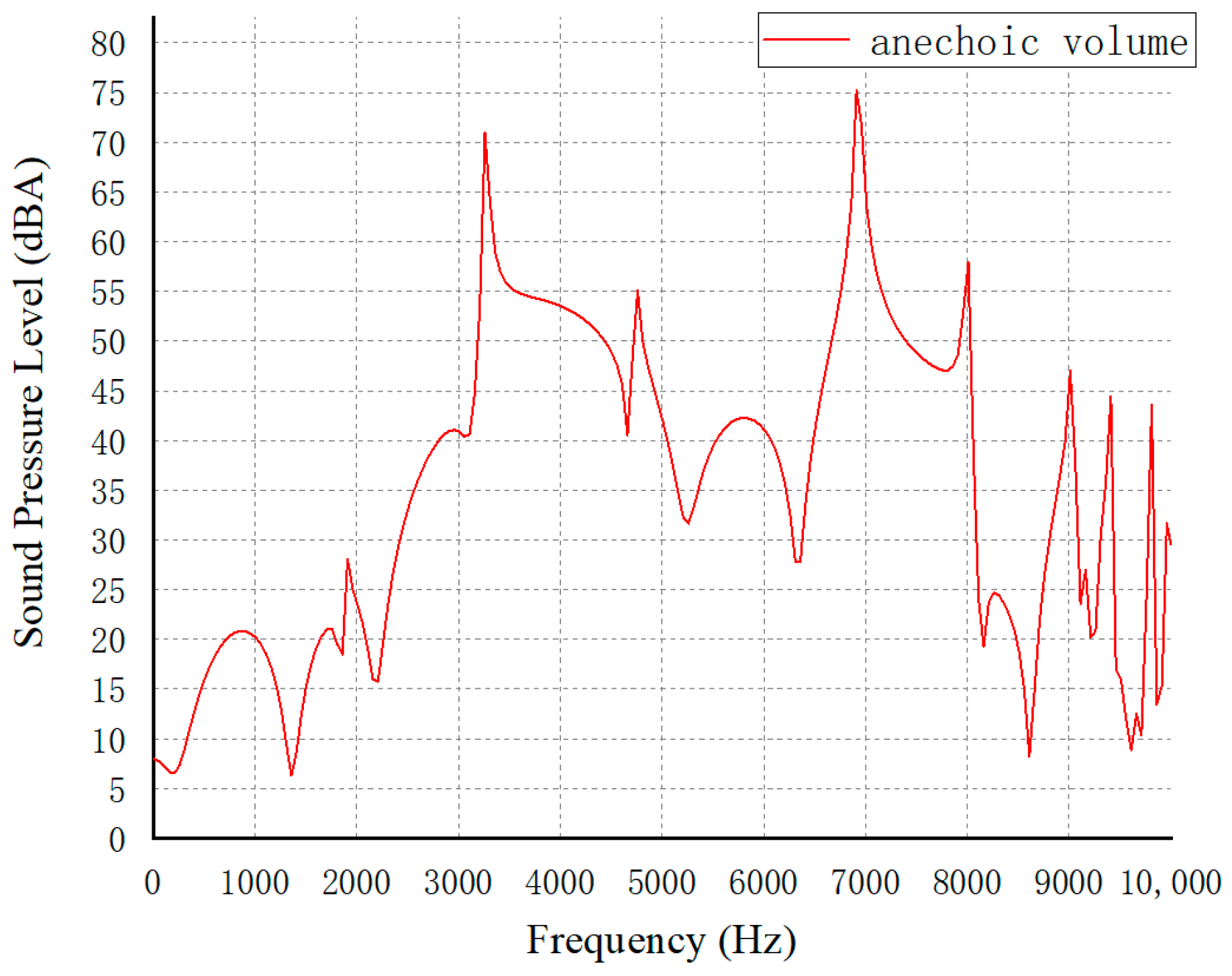
(5)
The inserted pipe structure can reduce the pressure loss generated by the chamber structure and improve the anechoic capacity, with a maximum value of 75.20 dBA, indicating that the inserted pipe structure can also improve the muffling effect.
Overall, the proposed design method can effectively reduce the noise level generated by the valves of an automobile scroll compressor, and the evaluation results show that the proposed design has significant advantages over the conventional design.

Author Contributions

Conceptualization, B.Y.; Data curation, F.G.; Investigation, F.G. and B.Y.; Methodology, B.Y.; Software, F.G. and B.Y.; Supervision, X.L.; Visualization, J.W.; Writing—original draft, F.G.; Writing—review and editing, F.G. All authors have read and agreed to the published version of the manuscript.

Funding

This study was supported by the National Natural Science Foundation of China (Grant No. 12372079) and the Natural Science Foundation of Jiangsu Province, China, (Grant No. BK20201470, BK20220687) and Fund of Nanjing Institute of Technology (Grant No. CKJB202205).

Institutional Review Board Statement

Not applicable.

Informed Consent Statement

Not applicable.

Data Availability Statement

Data are contained within the article.

Conflicts of Interest

The authors declare no conflicts of interest.

References

  1. Son, Y.; Choi, J.; Lee, S. Noise radiation analysis of the hermetic reciprocating compressor by considering acoustic-structure interaction. J. Mech. Sci. Technol. 2023, 37, 607–615. [Google Scholar] [CrossRef]
  2. Sun, X.D.; Lu, H.J.; Sun, H.; Liu, C. Research on the Radiating Characteristics of Aerodynamic Noise of Compressor Suction Silencer. Noise Vib. Control 2017, 37, 194–198. [Google Scholar]
  3. Chen, Q.; Zhang, J.; Jiang, Z.X. Experimental Study on Aerodynamic Noise of Automotive Air Conditioning and Engineering Application Based on Direct Simulation Method of LBM. J. Mech. Des. 2020, 37, 208–214. [Google Scholar]
  4. Galindo, J.; Tiseira, A.; Navarro, R.; Tarí, D.; Meano, C.M. Effect of the inlet geometry on performance, surge margin and noise emission of an automotive turbocharger compressor. Appl. Therm. Eng. 2017, 110, 875–882. [Google Scholar] [CrossRef]
  5. Shen, J.; Chen, W.; Yan, S.; Zhou, M.; Liu, H. Study on the noise reduction methods for a semi-hermetic variable frequency twin-screw refrigeration compressor. Int. J. Refrig. 2021, 125, 1–12. [Google Scholar] [CrossRef]
  6. Ji, J.; Jia, J.; Yi, F. Analysis and control of idle noise of vortex automobile air-conditioning compressor. Compress. Technol. 2018, 5, 40–42+47. [Google Scholar]
  7. Wu, H.; Shen, Y.; Liang, M.; Liu, J.; Wu, J.; Li, Z. Performance Research and Optimization of Sound Insulation Hood of Air Compressor Unit. Appl. Sci. 2021, 11, 10364. [Google Scholar] [CrossRef]
  8. Sun, S.; Xing, Z.; Chen, W.; Zhou, M.; Wang, C.; Cui, H. Study on Characteristics and Control of Aerodynamic Noise of a High-Speed Centrifugal Air Compressor for Vehicle Fuel Cells. Appl. Sci. 2022, 12, 9962. [Google Scholar] [CrossRef]
  9. Han, K.J.; Ji, Z.L.; Ma, X.Y. Design and experimental verification of intake muffler for turbocharged diesel engine. Trans. Chin. Soc. Intern. Combust. Engines 2022, 4, 331–337. [Google Scholar]
  10. Zhang, Z.G.; Gao, L.; Sun, H.B.; Lan, T.Y.; Wu, W. Design and optimization of intake silencer for reciprocating compressor. Noise Vib. Control 2022, 42, 231–235. [Google Scholar]
  11. Chen, Q.; Jiang, J.; Wang, Z.; Chen, X.; Zhao, S.; Zhang, H.; Hu, H. Broadband muffler with acoustic bright and dark modes for refrigerator noise control. Appl. Acoust. 2023, 211, 109471. [Google Scholar] [CrossRef]
  12. Dianov, A. Stoppage noise reduction of reciprocating compressors. IEEE Trans. Ind. Appl. 2021, 57, 4376–4384. [Google Scholar] [CrossRef]
  13. Zhang, Y.; Sun, S.; Xing, Z.; Chen, W.; Zhou, M.; Zhang, Z. Study on noise characteristics of two-stage centrifugal air compressor for fuel cell. In Proceedings of the 2020 IEEE 3rd International Conference on Renewable Energy and Power Engineering (REPE), Edmonton, AB, Canada, 9–11 October 2020; pp. 26–33. [Google Scholar]
  14. He, Z.; Li, D.; Han, Y.; Zhou, M.; Xing, Z.; Wang, X. Noise control of a twin-screw refrigeration compressor. Int. J. Refrig. 2021, 124, 30–42. [Google Scholar] [CrossRef]
  15. Ebrahimi-Nejad, S.; Rahimi, D.; Kheybari, M.; Majidi-Jirandehi, A.A. Effects of inlet-outlet positioning, muffler geometry, and baffle design on vehicle muffler performance for desired sound transmission loss, Proceedings of the Institution of Mechanical Engineers. Part D J. Automob. Eng. 2023, 237, 1160–1169. [Google Scholar] [CrossRef]
  16. Xia, Z. Influence analysis of structural parameters on the performance of reactive muffler. Mach. Des. Manuf. 2020, 4, 216–218+222. [Google Scholar]
  17. GB/T 4980-2003; Determination of Sound Level for Noise Emitted by Displacement Compressors. Standardization Administration of the People’s Republic of China: Beijing, China, 2022.
  18. Xiang, L.Y.; Zuo, S.G.; Wu, X.D.; Zhang, J.; Liu, J.F. Analysis and structural optimization of a dual-chamber reactive muffler for vehicles. Trans. Chin. Soc. Agric. Eng. 2015, 31, 65–71. [Google Scholar]
  19. Khairuddin, M.H.; Said Mohd, F.M.; Dahlan, A.A.; Kadir, K.A. Review on resonator and muffler configuration acoustics. Arch. Acoust. 2018, 43, 369–384. [Google Scholar]
Figure 1. Scroll compressor working principle diagram. (a) inspiratory; (b) start of compression; (c) compression process; (d) ventilate.
Applsci 14 04875 g001
Figure 2. Waveforms and background noise spectra throughout the semi−anechoic chamber.
Applsci 14 04875 g002
Figure 3. Compressor observation points.
Applsci 14 04875 g003
Figure 4. Sound pressure levels at observation points.
Applsci 14 04875 g004
Figure 5. Compressor lower end position.
Applsci 14 04875 g005
Figure 6. The 1/3 spectrum of sound pressure level at the lower end of the compressor.
Applsci 14 04875 g006
Figure 7. Primary structure runner mesh.
Applsci 14 04875 g007
Figure 8. Receiving point 1 position.
Applsci 14 04875 g008
Figure 9. Comparison between simulation and experimental results.
Applsci 14 04875 g009
Figure 10. Schematic diagram of the structure of an ideal expansion muffler.
Applsci 14 04875 g010
Figure 11. Structural noise simulation of the original chamber.
Applsci 14 04875 g011
Figure 12. Schematic diagram of end cap before modification.
Applsci 14 04875 g012
Figure 13. Schematic diagram muffler room.
Applsci 14 04875 g013
Figure 14. Schematic diagram of improved end cap improvement.
Applsci 14 04875 g014
Figure 15. Unmodified chamber surface sound power level.
Applsci 14 04875 g015
Figure 16. Modified chamber surface sound power level.
Applsci 14 04875 g016
Figure 17. Comparison of sound pressure levels at receiving point 1.
Applsci 14 04875 g017
Figure 18. Improved structure.
Applsci 14 04875 g018
Figure 19. Improved structure receiving point 1 transfer loss.
Applsci 14 04875 g019
Table 1. Valve material parameters.
Compressor ComponentsMaterial
Stationary scroll diskHT250
Compressor end capsaluminum
RefrigerantsR134a
Table 2. Valve operating conditions.
Calculation ParametersValue
Refrigerant   density / ( k g / m 3 ) 5.64
Refrigerant   thermal   conductivity / ( W / ( m × k ) ) 0.009
Inlet   Pressure / ( M P a ) 2.5
Inlet   temperature / ( ) 80
Outlet   pressure / ( M P a ) 1.75
Outlet   temperature / ( ) 72
Disclaimer/Publisher’s Note: The statements, opinions and data contained in all publications are solely those of the individual author(s) and contributor(s) and not of MDPI and/or the editor(s). MDPI and/or the editor(s) disclaim responsibility for any injury to people or property resulting from any ideas, methods, instructions or products referred to in the content.

