Article

An Assessment of the Eurocode 3 Simplified Formulas for Distortional Buckling of Cold-Formed Steel Lipped Channels

1
IDMEC (Institute of Mechanical Engineering), Instituto Superior Técnico, University of Lisbon, 1049-001 Lisbon, Portugal
2
Faculty of Engineering, Universidade Lusófona, 1749-024 Lisbon, Portugal
3
CERIS, Instituto Superior Técnico, University of Lisbon, 1049-001 Lisbon, Portugal
4
Faculdade de Ciências e Tecnologia, Universidade Nova de Lisboa, Campus de Caparica, 2829-516 Caparica, Portugal
5
CERIS and Departamento de Engenharia Civil, Faculdade de Ciências e Tecnologia, Universidade Nova de Lisboa, Campus de Caparica, 2829-516 Caparica, Portugal
*
Author to whom correspondence should be addressed.
Appl. Sci. 2024, 14(11), 4924; https://doi.org/10.3390/app14114924
Submission received: 30 April 2024 / Revised: 27 May 2024 / Accepted: 3 June 2024 / Published: 6 June 2024
(This article belongs to the Special Issue Steel Structural Stability in Civil Engineering)

Abstract

:
This paper concerns the Eurocode 3 Part 1-3 (EN 1993-1-3) methods for calculating the distortional buckling (bifurcation) load of cold-formed steel-lipped channels subjected to axial force, major and minor axis bending. More specifically, the paper presents the results of a parametric study that assesses the accuracy of the simplified method in EN 1993-1-3, which relies on direct/iterative hand calculations and an approximate mechanical model, through comparison with “exact” numerical results, obtained using semi-analytical linearized buckling analyses based on Generalized Beam Theory, which are also allowed by the code. Isoline error maps are presented for a wide range of geometric and material parameters, covering common commercial profiles and corresponding to a dataset of more than 24,000 cases. These maps make it possible to identify the parameter ranges leading to an acceptable error and, even though they strongly depend on the loading, general remarks concerning the expected error pertaining to the simplified method are drawn.

1. Introduction

Cold-formed steel members enjoy a remarkable popularity, being widely used as structural elements in the construction industry, namely in residential buildings, storage racks, trusses, purlins, roofing and wall systems [1,2]. However, their design is rather challenging, due to their thinness and consequent susceptibility to complex buckling phenomena, namely local (plate type), distortional and coupled phenomena.
Distortional buckling is significantly more complex than local buckling, since it involves not only transverse wall bending, but also warping and cross-section in-plane motions of the fold lines. Consequently, it is quite difficult to obtain accurate distortional bifurcation loads (which are required by the design codes) using approximate mechanical models, particularly for complex cross-sections. Even though such simplified models exist [3,4,5], which invariably consider the part of the cross-section undergoing distortional buckling as an elastically supported strut, a rigorous calculation requires performing a numerical linearized buckling analysis using shell finite elements, finite strips or Generalized Beam Theory (see, e.g., [6,7,8]).
The European design code for cold-formed members—EN 1993-1-3 [9], or simply Eurocode 3 Part 1-3—constitutes no exception with regard to the requirement for calculating the distortional bifurcation load, and allows using either numerical linearized buckling analyses (the numerical method) or formulas based on a simplified mechanical model (the simplified method). The simplified method is traditionally used, but the recent availability of freeware programs such as CUFSM [10] and GBTUL [11] is expected to change the picture, since they allow obtaining accurate local–distortional–global bifurcation loads with a negligible computational and time cost. This change is already noticeable in North America, where the American Iron and Steel Institute has sponsored research that, in part, has led to the development of CUFSM (see Appendix 2 of [12]).
For the particular case of lipped channels, which are profusely used in practice, EN 1993-1-3 provides analytical formulas for the distortional bifurcation load (simplified method). However, as shown in this paper, the results can differ significantly from those obtained with an accurate numerical method, both on the safe and unsafe sides, even for typical cross-section geometries. To the authors’ best knowledge, the papers most closely related to this topic are those by Carvalho and Prola [13,14], where resistances obtained from experiments (not bifurcation loads), taken from the literature [15,16,17], are compared with values obtained using EN 1993-1-3 (simplified and numerical methods) for columns [13] and beams bent about the major axis [14] only. Moreover, in these papers, a limited set of lipped channels were analyzed, thus there is still the need for an in-depth investigation into the accuracy of the simplified method. This work aims to fill this gap.
This paper presents the results of a parametric study that assesses the accuracy of the simplified method in EN 1993-1-3 for calculating the distortional buckling (bifurcation) load of standard lipped channels subjected to axial force, major and minor axis bending. A wide range of parameter values is considered, covering common commercial products and corresponding to a total of 24,000 cases. The accuracy is measured with respect to the “exact” values, obtained using the numerical method, more specifically semi-analytical linearized buckling analyses using Generalized Beam Theory, which are also allowed in EN 1993-1-3.
The outline of the paper is as follows. Section 2 discusses the fundamental aspects related to the calculation of the distortional buckling loads using the numerical and simplified methods prescribed in EN 1993-1-3. The results of the extended parametric study carried out are presented and discussed in Section 3. The paper closes in Section 4 with the concluding remarks.

2. Calculation of Distortional Buckling Loads

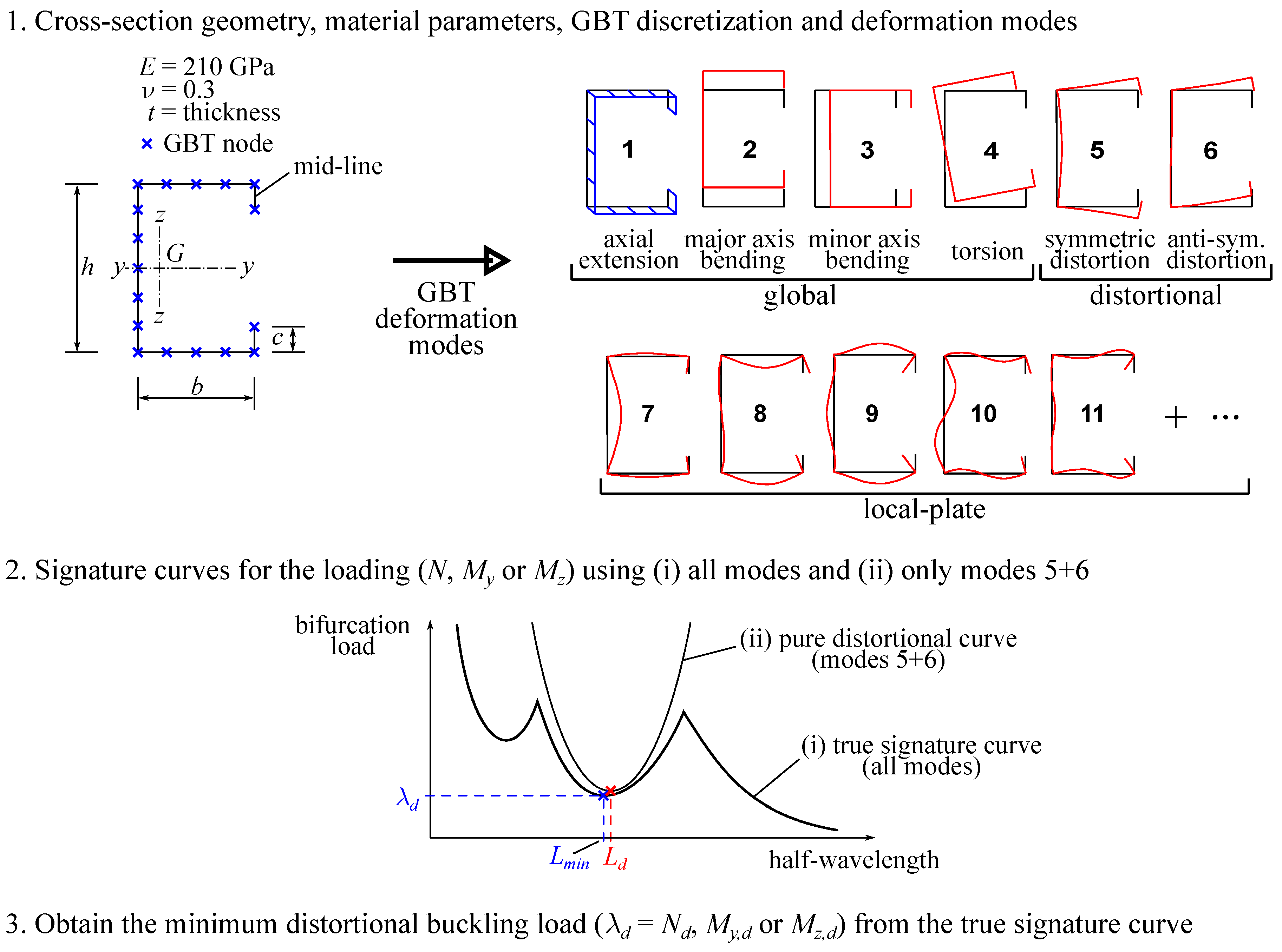
2.1. Numerical Method

In this work, the distortional buckling loads according to the numerical method in EN 1993-1-3, are calculated using the semi-analytical form of Generalized Beam Theory [18], as implemented in the GBTUL program [11], which is freely available from https://sites.fct.unl.pt/gbt/. This constitutes an accurate and computationally efficient method to (i) retrieve the so-called “signature curve” pioneered by Hancock [7]—the buckling load as a function of the buckling mode half-wavelength, as required by EN 1993-1-3—and (ii) identify the nature of the buckling mode at the relevant half-wavelengths (local, distortional or global). It is worth noting that, even though GBT-based analytical formulas for distortional buckling have been proposed [19,20,21], they are not used in this work, due to their inherent simplifications.
For many cross-section geometries, the minimum distortional buckling load corresponds to a local minimum of the signature curve, but this is not always the case. For this reason, the determination of the minimum distortional buckling load λ d for either axial force ( N d ), major axis bending ( M y , d ) or minor axis bending ( M z , d causing compression in the lips) was performed in the following steps (see Figure 1):
  • Definition of the cross-section geometry, material parameters and GBT cross-section discretization, which allows for calculating the so-called “GBT cross-section deformation modes” (global, distortional and local-plate). To ensure obtaining accurate results, the cross-section discretization adopted involves five intermediate nodes in the web and three intermediate nodes in each flange.
  • Calculation of the signature curve for the loading considered using (i) all deformation modes (the true signature curve) and (ii) only the distortional modes 5 + 6 (the pure distortional curve). The pure distortional curve is used to obtain L d , the half-wavelength corresponding to the minimum of the curve, which serves as an initial estimate for L m i n , the true distortional minimum (which generally has contributions from the local-plate modes).
  • The minimum distortional buckling load λ d is searched on the true signature curve, within a reasonable interval centered on L d . If the minimum does not correspond to a stationary point, which can occur for certain geometries, the value corresponding to L d is adopted.
The procedure is executed in batch processing, using a MATLAB [22] script.
The GBT semi-analytical solution for distortional buckling in a single deformation mode allows obtaining directly the minimum distortional buckling load and the corresponding half-wavelength, through [8]
λ d = D d + 2 C d B d X d ,
L m i n = π C d B d 4 ,
where λ d is the minimum distortional buckling load, B d , C d , D d and X d are cross-section stiffness properties associated with distortion— B d relates to plate-like transverse wall bending, C d to warping (membrane and bending), D d to plate-like torsion and Poisson couplings, and X d to the geometric non-linear effects associated with the loading considered. These cross-section stiffness properties can be obtained from the GBTUL output.

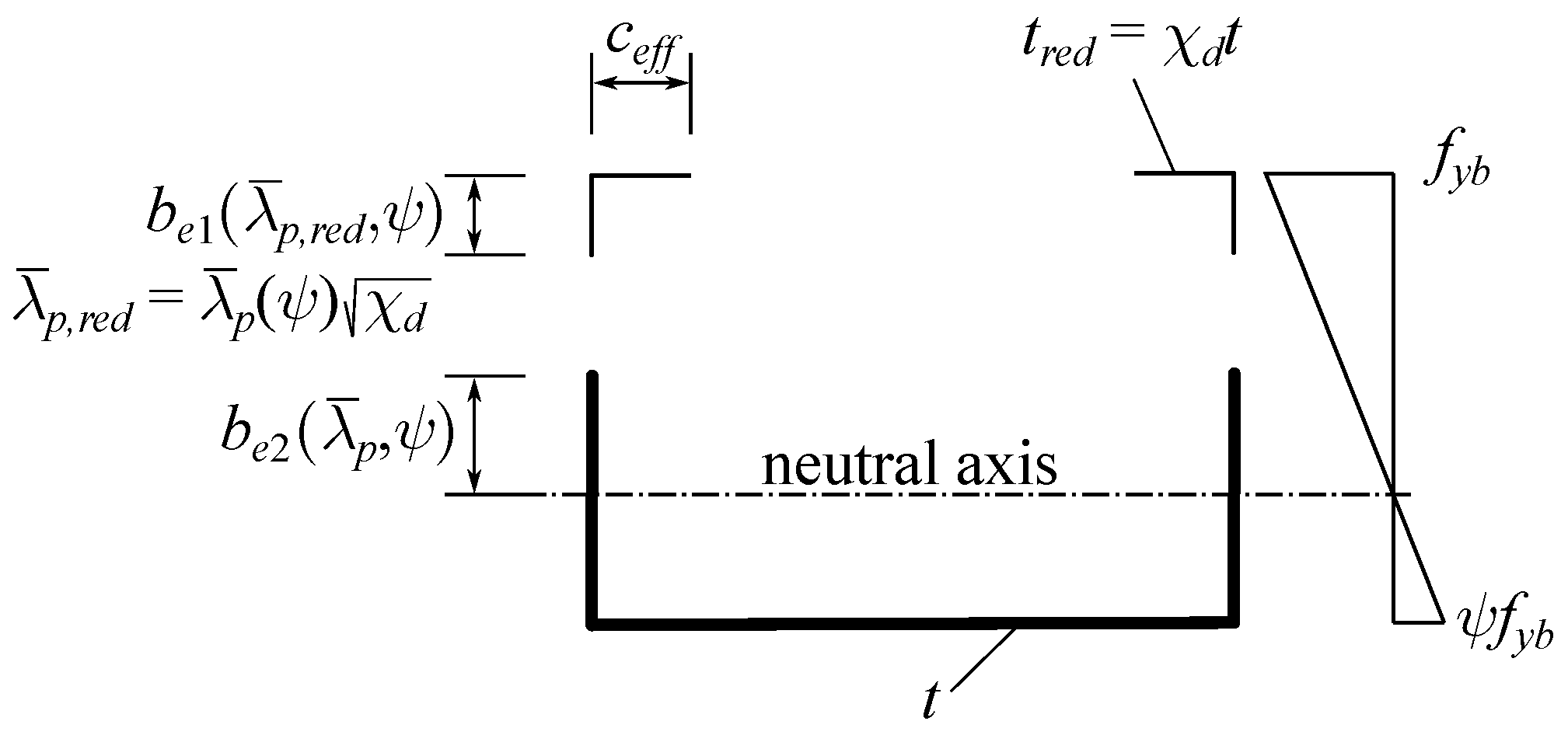
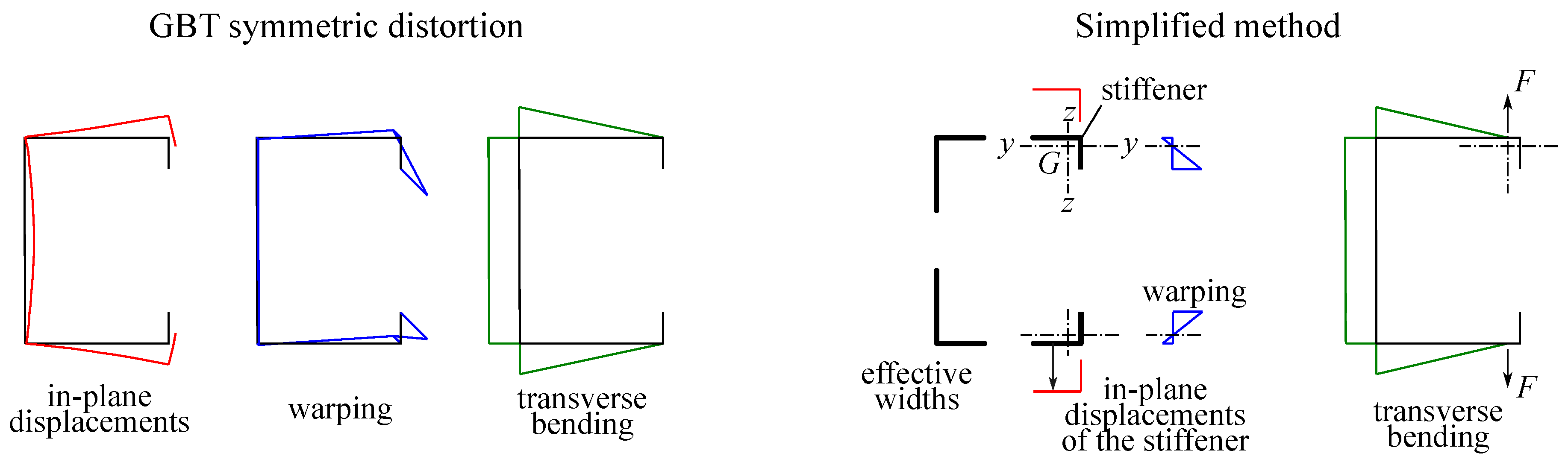
2.2. Simplified Method

Standard approximate mechanical models for the calculation of the distortional buckling load invariably rely on the analysis of the part of the cross-section undergoing buckling. While early models consider the whole flange and lip [3], the simplified method of EN 1993-1-3 instead considers a reduced section (the “stiffener”) that also accounts for local buckling. The “strut” cross-section, therefore, involves the effective part of the lip and of the adjacent flange. The calculation procedure is covered well in several textbooks (e.g., [2,23]), and therefore will not be explained in detail here. It is nevertheless worth recalling that the procedure can be either “direct” (without iterations) or “iterative”.
The iterative method is rather straightforward for axial force and major axis bending, and detailed examples concerning lipped channels can be found in [23]. However, the procedure can be quite involved for minor axis bending, and the only example in [23] has fully effective walls due to local buckling, hence no iterations are carried out. The procedure adopted in this paper carries out iterations until the convergence of the effective section, in accordance with Figure 2.
The distortional buckling load is obtained using Equation (1), assuming that the stiffener is a strut undergoing flexural buckling, hence (see [8]) D d = 0 (no plate-like torsion), X d = 1 and C d = E I s (bending stiffness of the strut about its central axis). The transverse bending stiffness B s is designated as K s , and is calculated as explained below. The buckling stress in the stiffener is therefore given by
σ d , s = 2 E I s K s A s .
For illustrative purposes, Figure 3 concerns the uniform compression case, and shows (i) the GBT distortional deformation mode in-plane (left) and out-of-plane (center) displacements, as well as the associated transverse bending moment diagram (right), and (ii) the EN 1993-1-3 simplified method effective section for the calculation of the stiffener (left), together with the assumed in-plane/out-of-plane displacements of the stiffener, and the model used to obtain the transverse bending stiffness K s (right), which consists of lateral forces acting at the stiffener centroid, causing the bending moment diagram shown. Clearly, the displacements and transverse bending of the two approaches agree reasonably well in this case, but it is remarked that the full GBT numerical method includes more deformation modes in the analysis (namely local-plate modes) and, more importantly, the definition of the stiffener cross-section in the simplified method depends on effective widths for local buckling—no such effect is considered in the numerical method. In fact, it is remarked that, since the effective widths depend on the basic yield stress f y b , in the simplified method, the distortional buckling stress becomes dependent on this parameter.

3. Parametric Study

3.1. Scope

The range of parameter values adopted covers common commercial cross-section geometries and materials. This led to the selection of two basic yield stress values— f y b = 200, 700 MPa, extrema values—and three width-to-thickness ratios— b / t = 20, 35, 50. The geometry ranges considered are 1.5 h / b 6.0 and 0.2 c / b 0.5 , which comply with the geometric proportion limits defined in EN 1993-1-3, clause 5.2. The corner radii are neglected.
For all combinations of the selected values, isoline maps are presented for the error
ϵ = σ d , s N σ d , s S σ d , s N ,
where S and N designate the simplified and numerical methods, respectively. For the simplified method, both direct and iterative calculations are carried out. For the numerical method, the distortional buckling stress is calculated at the stiffener centroid, a procedure that requires the determination of the stiffener effective section using either the direct or iterative simplified methods (depending which one is being assessed with Equation (4)). Error maps are also reported when the stress for the numerical method is calculated at the most compressed fiber (a considerably simpler task). For visualization purposes, the 10 % ϵ 10 % regions in each map are shaded. Each map is generated using the contour function in MATLAB, on the basis of a 20 × 20 even-spaced point grid. A total of 24,000 points are calculated.

3.2. Results and Discussion
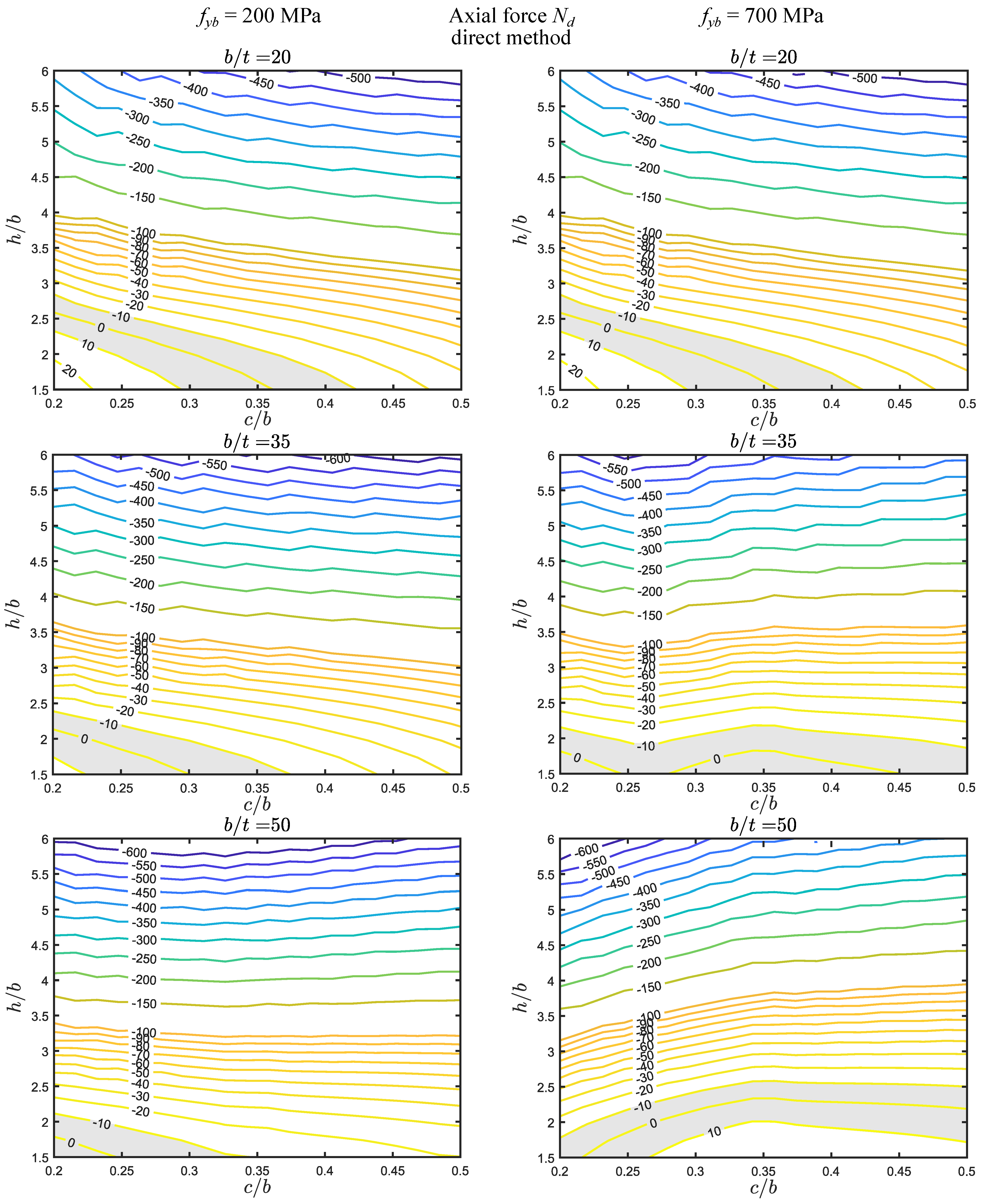
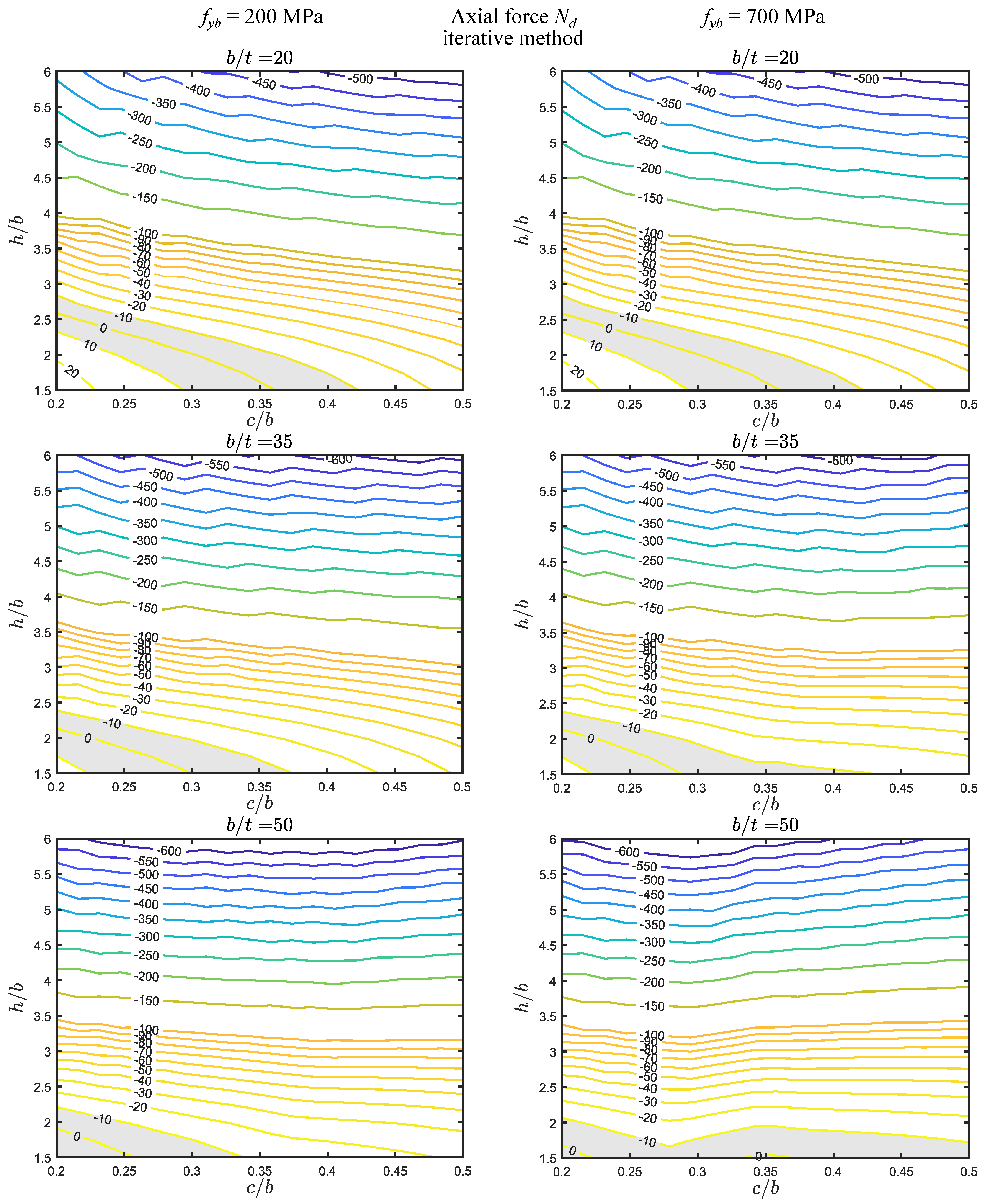
The results for axial force are displayed in Figure 4 and Figure 5, for the direct and iterative methods, respectively. The observation of these results prompts the following remarks:
(i)
The errors are in the approximate range of 600 % < ϵ < 20 % . The shaded ± 10 % regions are located in the lower left corner of the maps—closer to the corner as b / t increases—even if, for some cases, they extend up to the right side. These regions are quite small with respect to the parameter ranges considered.
(ii)
A comparison between the direct and iterative methods reveals that they (I) coincide for b / t = 20 + f y b = 200 , 700 MPa and b / t = 35 + f y b = 200 MPa, (II) are very similar for b / t = 50 + f y b = 200 MPa, and (III) are somewhat different in the two remaining cases ( b / t = 35 , 50 + f y b = 700 MPa), with the shaded ± 10 % regions being quite smaller for the iterative method.
(iii)
The yield stress has no effect for b / t = 20 (and a very small effect for b / t = 35 , iterative method) since, for these cases, there is no reduction in the stiffener wall widths due to local buckling. For the remaining cases, the isoline slopes are slightly changed and the differences observed in the direct method maps can be somewhat significant.
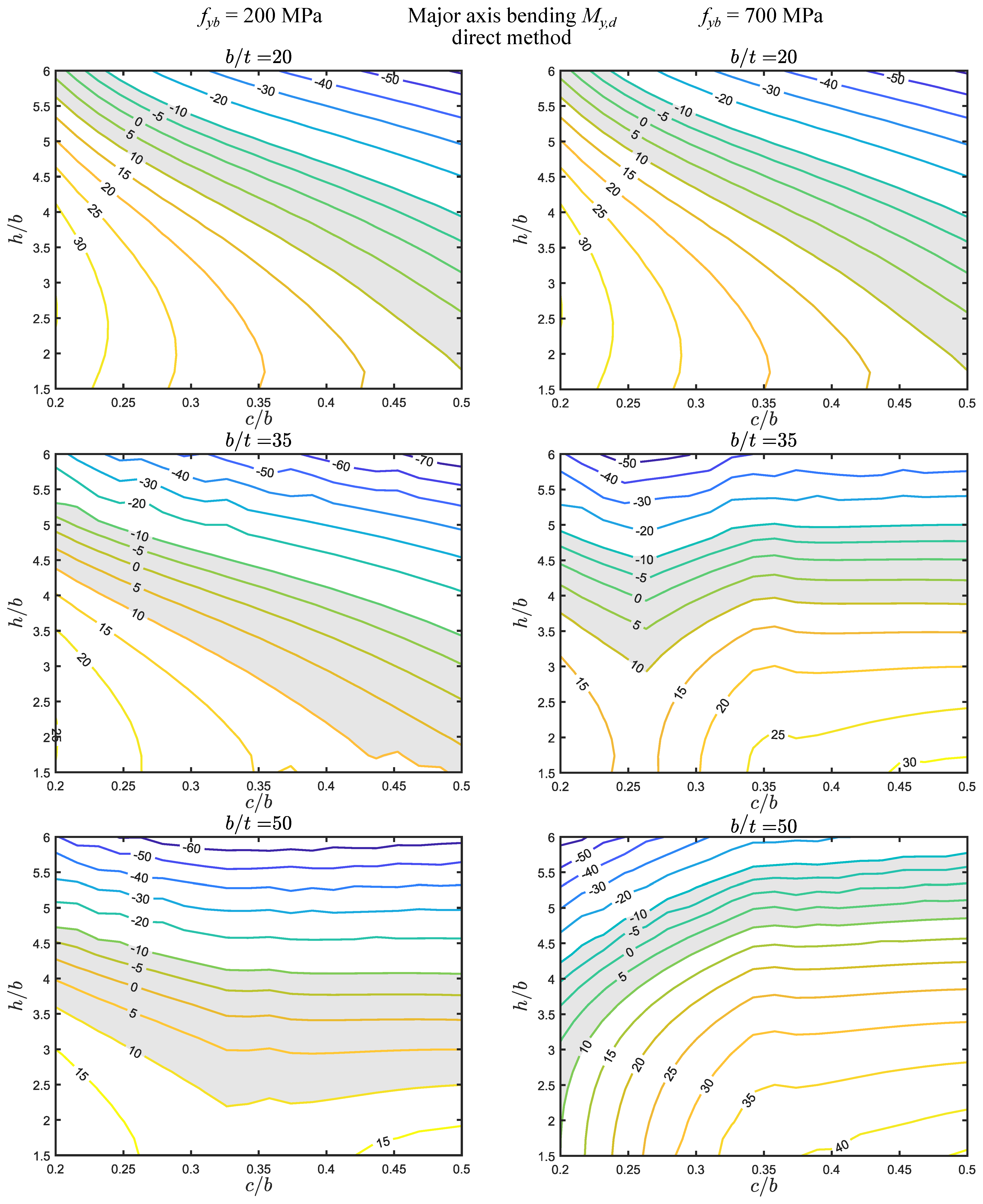
For major axis bending, the results are presented in Figure 6 and Figure 7 (direct and iterative methods, respectively), and deserve the following comments:
(i)
The errors are smaller than for axial force, falling approximately between 70 % and 45 % . The shaded ± 10 % regions are wider than for axial force, and are now located diagonally or horizontally, in the middle of the maps.
(ii)
As for axial force, the direct and iterative methods (I) coincide for b / t = 20 + f y b = 200 , 700 MPa and b / t = 35 + f y b = 200 MPa, and (II) are very similar for b / t = 50 + f y b = 200 MPa. However, they are now remarkably different in the two remaining cases ( b / t = 35 , 50 + f y b = 700 MPa), even if both methods yield shaded ± 10 % regions with similar areas and therefore have a similar accuracy (but obviously for different parameter ranges).
(iii)
Also, as for axial force, the yield stress has no effect for b / t = 20 . For the remaining cases, the changes in the maps can be quite significant, particularly for the direct method.
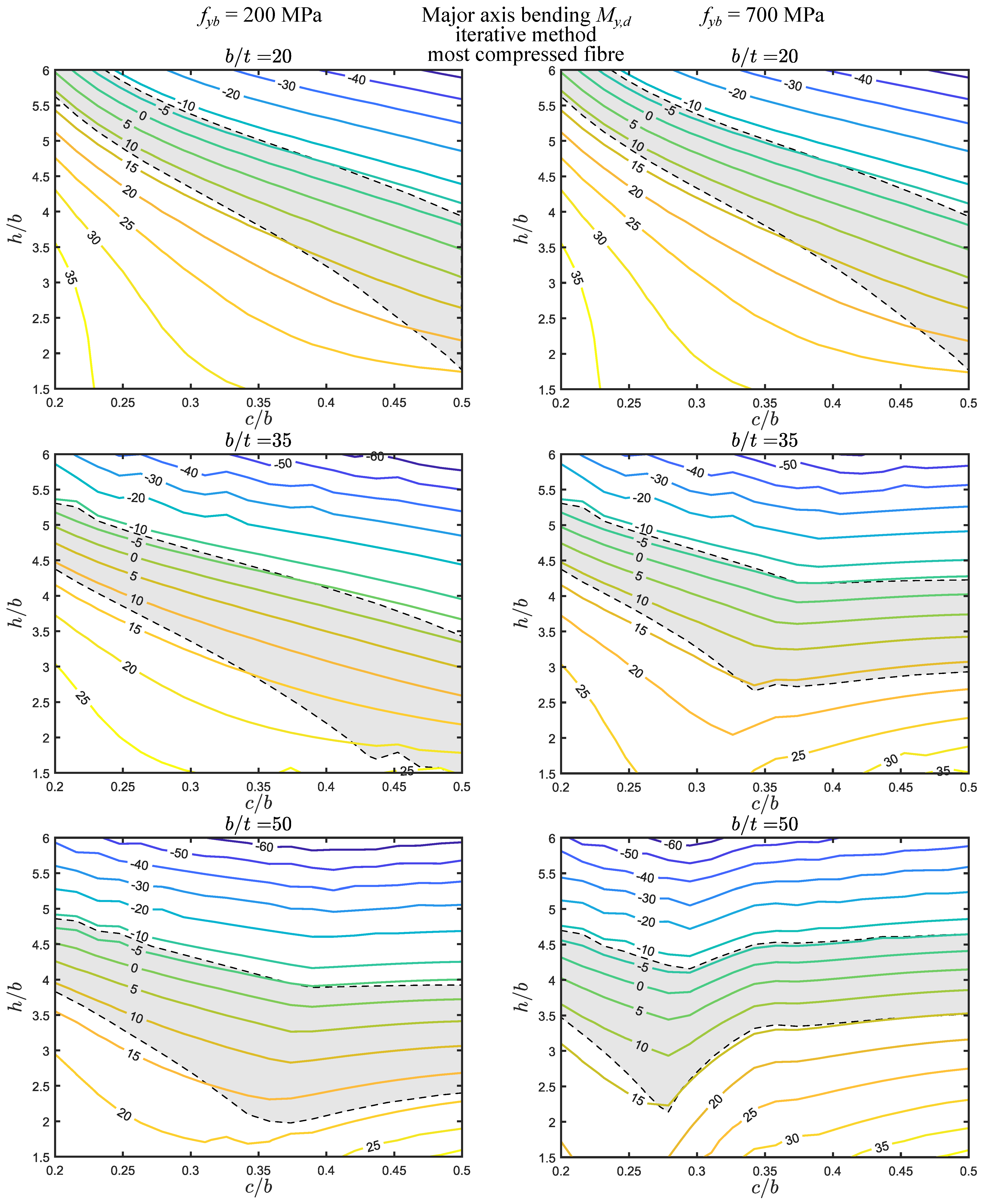
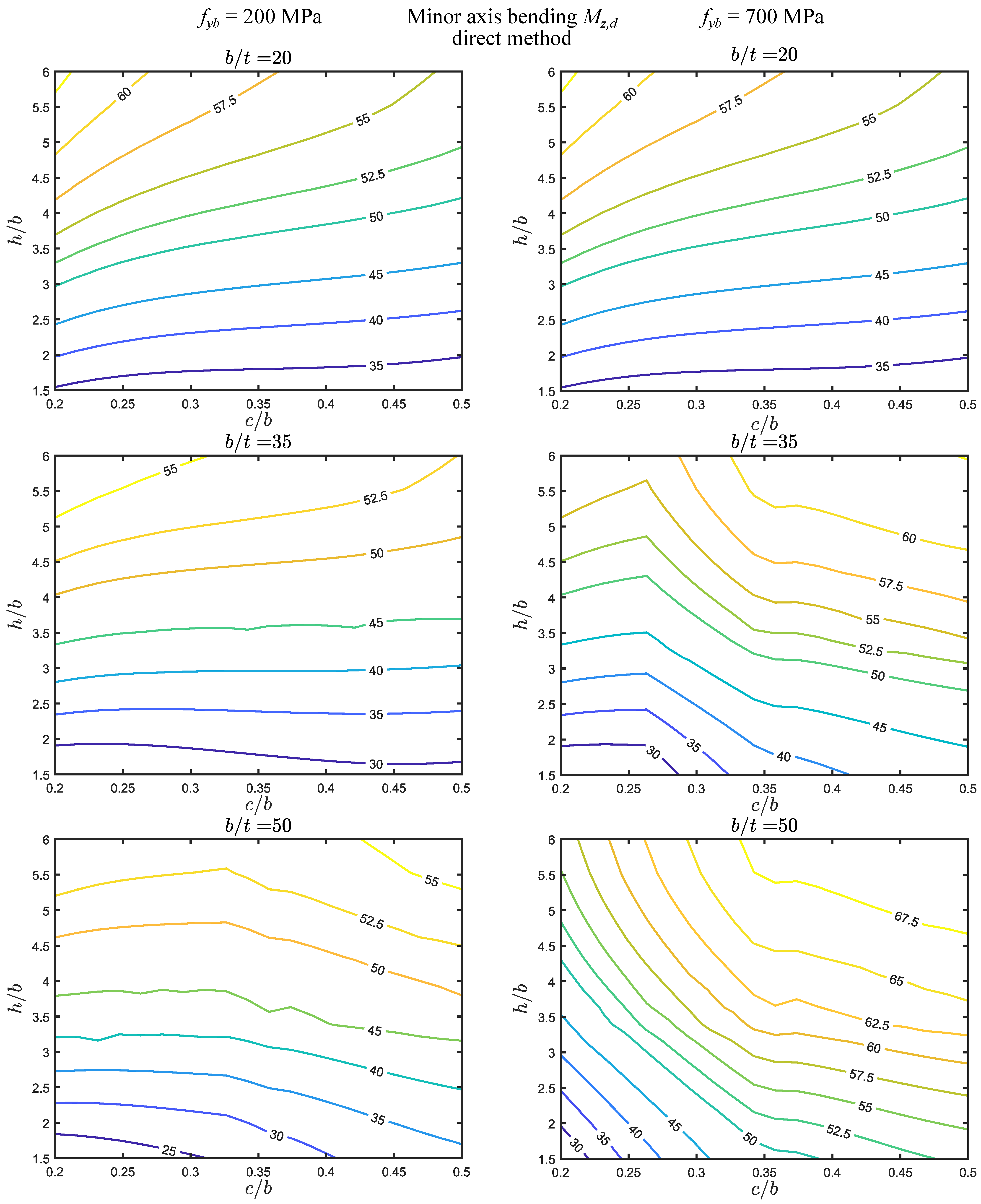
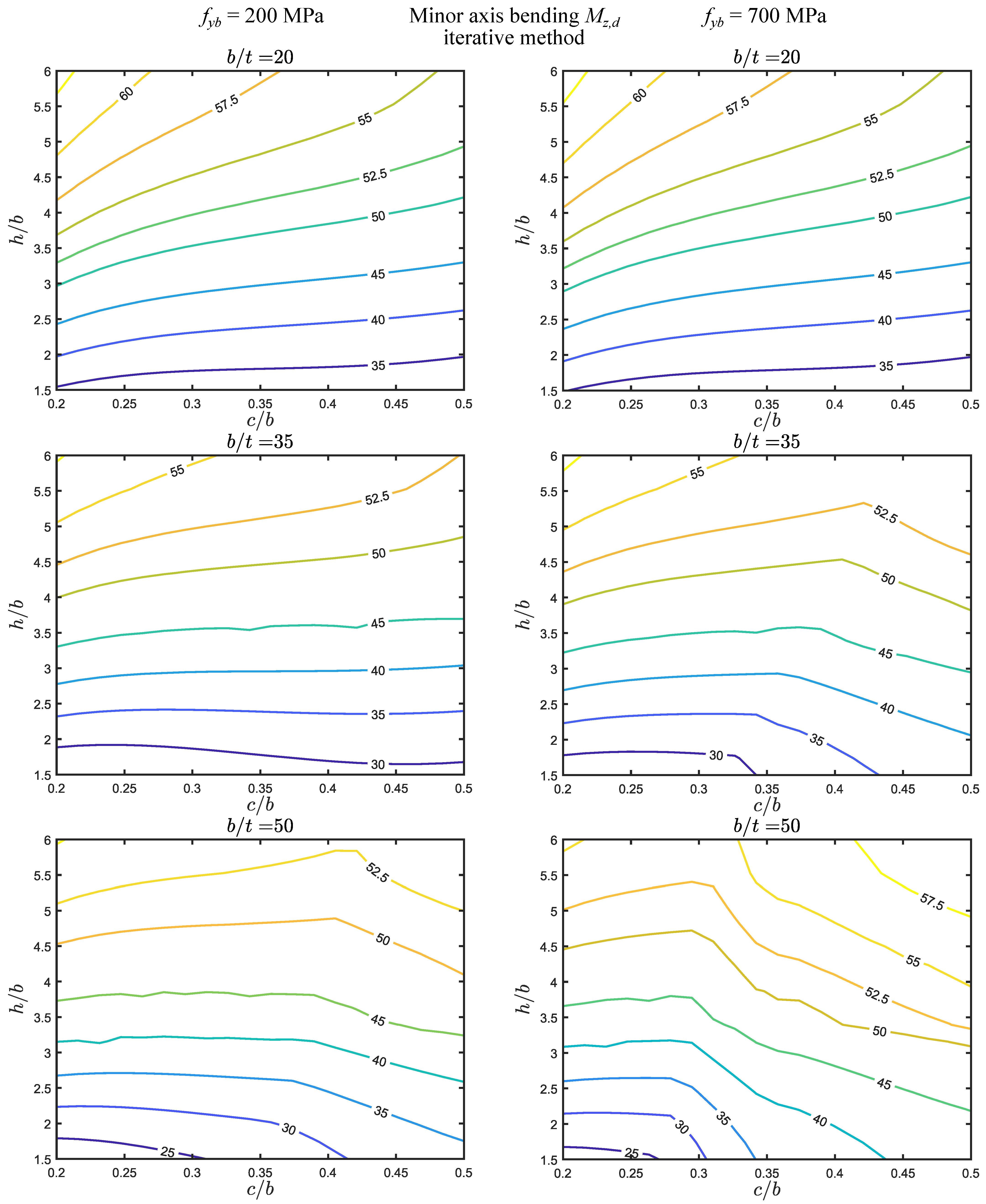
It is of interest to examine the differences in the error maps when the numerical distortional stress is calculated using the distance from the neutral axis to the most compressed fiber ( h / 2 + t / 2 ), instead of the distance to the stiffener centroid, a procedure that avoids the calculation of the stiffener effective section. The results are shown in Figure 8 and Figure 9, where the shaded areas correspond to the ± 10 % regions of the corresponding graphs in Figure 6 and Figure 7, to facilitate the comparison. In general terms, the differences in each map obviously increase as the differences between the two distances become more relevant (i) as h / b decreases, and (ii) as c / b increases. Thus, the differences are lower at the top-left corners and higher at the bottom-right corners, never exceeding 20%—the maximum difference occurs for b / t = 20 , regardless of the method or yield stress considered, and the differences decrease with increasing (i) b / t and (ii) yield stress. Concerning the ± 10 % regions, it is observed that using the most compressed fiber leads to a small decrease in the error on the negative side, but a significant increase in the error on the positive side.
Figure 10 and Figure 11 display the direct and iterative method results for minor axis bending, making it possible to draw the following remarks:
(i)
For this loading, the error range is the smallest, between approximately 25 and 60 % , but it is always above 20% and, therefore, the ± 10 % regions fall outside all maps shown.
(ii)
The comparison between the direct and iterative methods reveals a similar trend to that observed for axial force and major axis bending. Specifically, they (I) coincide for b / t = 20 + f y b = 200 , (II) are virtually coincident for b / t = 20 + 700 MPa and b / t = 35 + f y b = 200 MPa, and (III) are similar for b / t = 50 + f y b = 200 MPa. However, they are remarkably different in the two remaining cases ( b / t = 35 , 50 + f y b = 700 MPa).
(iii)
Regarding the influence of the yield stress, the trend is similar to that observed for the major axis bending case. The yield stress has virtually no effect for b / t = 20 , but the differences in the maps increase in the remaining cases, particularly for the direct method.
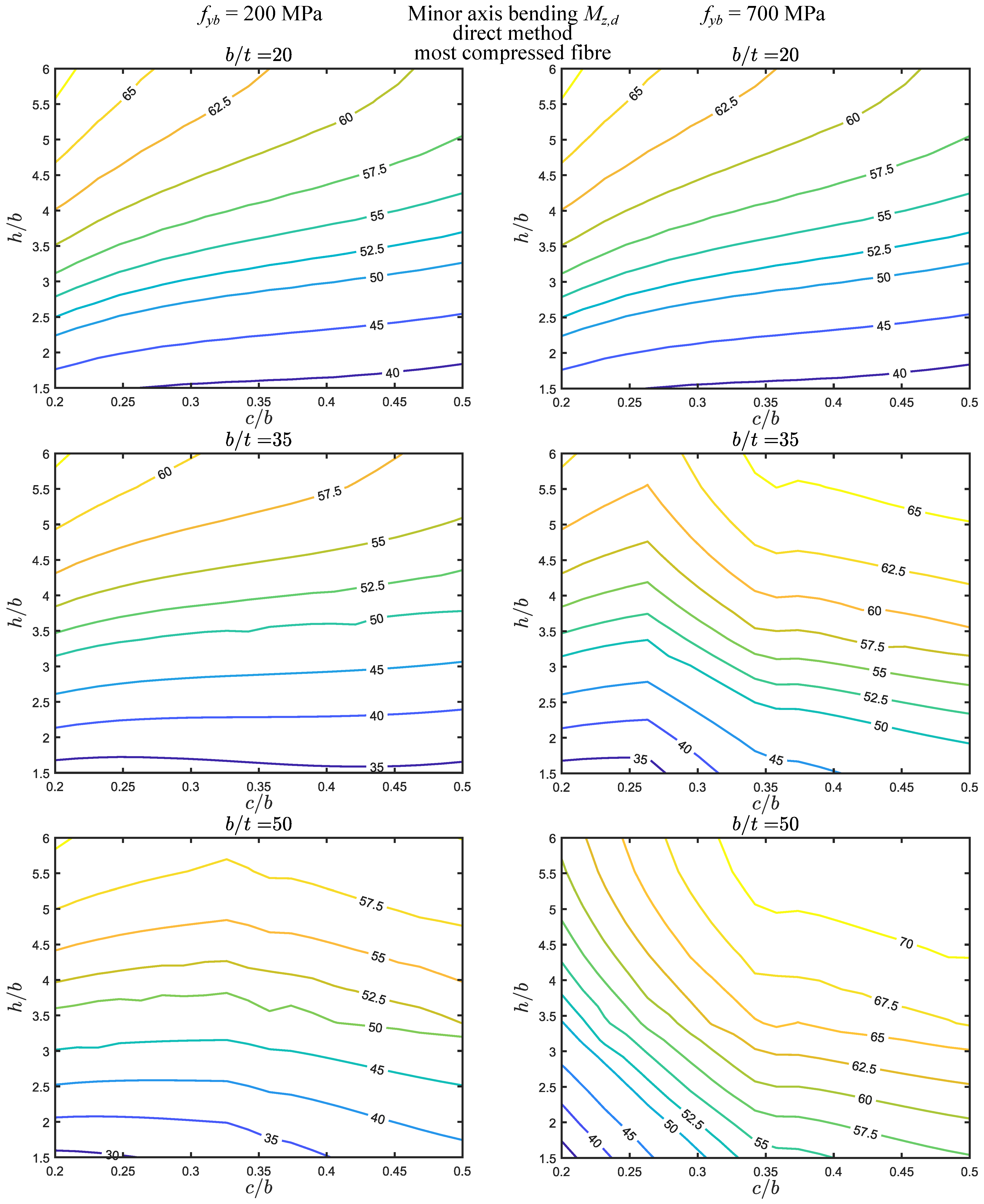
Finally, Figure 12 and Figure 13 display the error maps obtained when the numerical distortional stress is calculated using the distance from the neutral axis to the most compressed fiber, instead of the distance to the stiffener centroid. A comparison with Figure 10 and Figure 11 shows that, for the same parameter values, the error essentially increases 5% and never exceeds 10% (this maximum corresponds to b / t = 50 , iterative method, and f y b = 700 MPa).
Despite the fact that the results obtained for different loadings exhibit noteworthy differences, it is possible to draw the following general remarks for the parameter ranges considered:
(i)
The errors are significantly higher for axial force, followed by major axis bending and then minor axis bending. However, for the latter, the error is never zero, being always above 25%.
(ii)
The parameter ranges for which the error falls within ± 10 % were identified in each map. For axial force, these regions are generally located in the lower left corner ( h / b = 1.5 , c / b = 0.2 ), even if in some cases they extend up to the maximum c / b value considered ( c / b = 0.5 ). For major axis bending, the ± 10 % regions are wider and located in the middle of the maps, whereas for minor axis bending they fall outside the parameter ranges considered.
(iii)
The direct and iterative method results (I) coincide or are virtually coincident for b / t = 20 + f y b = 200 , 700 and b / t = 35 + f y b = 200 MPa, (II) are similar or very similar for b / t = 50 + f y b = 200 MPa, and (III) are different or remarkably different in the two remaining cases ( b / t = 35 , 50 + f y b = 700 MPa).
(iv)
The basic yield stress has virtually no effect for b / t = 20 and a rather small effect for b / t = 35 iterative method. For the remaining cases, the differences can be significant, particularly for the direct method.
(v)
The calculation of the numerical distortional stress using the distance to the most compressed fiber can lead to differences of up to 17.5 % for major axis bending (for low h / b and high c / b ) and 9 % for minor axis bending (for all parameter ranges).

4. Concluding Remarks

This paper presented the results of a significantly wide parametric study that assesses the accuracy of the direct/iterative simplified method in EN 1993-1-3 for the calculation of the distortional buckling (bifurcation) load of cold-formed lipped channels subjected to axial force, major or minor axis bending. The error was measured with respect to values obtained from semi-analytical linearized buckling analyses using Generalized Beam Theory, which are also allowed by the code. The results were presented in the form of isoline error maps (total of 60 maps), using a dataset of more than 24,000 points. These maps made it possible to identify the parameter ranges leading to an acceptable error. Even though the results strongly depend on the loading considered, it was possible to draw general remarks concerning the expected error for the simplified method.

Author Contributions

Investigation, A.D.M., N.P., P.J. and R.G. All authors have read and agreed to the published version of the manuscript.

Funding

This research was funded by Portuguese Foundation for Science and Technology’s (“Fundação para a Ciência e a Tecnologia”, FCT) support through funding (i) UIDB/04625/2020 from the research unit CERIS (DOI: 10.54499/UIDB/04625/2020) and (ii) the project LAETA Base Funding (DOI: 10.54499/UIDB/50022/2020).

Institutional Review Board Statement

Not applicable.

Informed Consent Statement

Not applicable.

Data Availability Statement

The raw data supporting the conclusions of this article will be made available by the authors on request.

Conflicts of Interest

The authors declare no conflict of interest.

References

  1. Ziemian, R. Guide to Stability Design Criteria for Metal Structures; Wiley: Hoboken, NJ, USA, 2010. [Google Scholar] [CrossRef]
  2. Dubina, D.; Ungureanu, V.; Landolfo, R. Design of Cold-Formed Steel Structures: Eurocode 3: Design of Steel Structures. Part 1-3 Design of Cold-Formed Steel Structures; Wiley: Hoboken, NJ, USA, 2012. [Google Scholar] [CrossRef]
  3. Lau, S.C.W.; Hancock, G.J. Distortional Buckling Formulas for Channel Columns. J. Struct. Eng. 1987, 113, 1063–1078. [Google Scholar] [CrossRef]
  4. Buhagiar, D.; Chapman, J.; Dowling, P. Design of C-sections against deformational lip buckling. In Proceedings of the CCFSS Proceedings of International Specialty Conference on Cold-Formed Steel Structures, St. Louis, MO, USA, 20–21 October 1992; University of Missouri: Rolla, MO, USA, 1992; pp. 1971–2018. [Google Scholar]
  5. Teng, J.; Yao, J.; Zhao, Y. Distortional buckling of channel beam-columns. Thin-Walled Struct. 2003, 41, 595–617. [Google Scholar] [CrossRef]
  6. Borges Dinis, P.; Camotim, D.; Silvestre, N. FEM-based analysis of the local-plate/distortional mode interaction in cold-formed steel lipped channel columns. Comput. Struct. 2007, 85, 1461–1474. [Google Scholar] [CrossRef]
  7. Hancock, G.J. Local, Distortional, and Lateral Buckling of I-Beams. J. Struct. Div. 1978, 104, 1787–1798. [Google Scholar] [CrossRef]
  8. Schardt, R. Generalized beam theory—An adequate method for coupled stability problems. Thin-Walled Struct. 1994, 19, 161–180. [Google Scholar] [CrossRef]
  9. EN 1993-1-3:2006; Eurocode 3: Design of Steel Structures—Part 1-3: General Rules—Supplementary Rules for Cold-Formed Members and Sheeting. CEN: Brussels, Belgium, 2009.
  10. Li, Z.; Schafer, B. Application of the finite strip method in cold-formed steel member design. J. Constr. Steel Res. 2010, 66, 971–980. [Google Scholar] [CrossRef]
  11. Bebiano, R.; Camotim, D.; Gonçalves, R. GBTUL 2.0—A second-generation code for the GBT-based buckling and vibration analysis of thin-walled members. Thin-Walled Struct. 2018, 124, 235–257. [Google Scholar] [CrossRef]
  12. AISI. North American Specification for the Design of Cold-Formed Steel Structural Members; American Iron and Steel Institute: Washington, DC, USA, 2016. [Google Scholar]
  13. Carvalho, C.; Prola, L. Cold-Formed Steel Profiles with Multiple Stiffeners Effective Section Calculation Using Alternative Methodology of the EN1993-1-3 Standard. ce/papers 2022, 5, 51–60. [Google Scholar] [CrossRef]
  14. Carvalho, C.; Prola, L. Moment Resistance Analysis of Thin-walled Stiffened Sections by the Alternative Method of EN1993: Part:1-3. ce/papers 2022, 5, 135–142. [Google Scholar] [CrossRef]
  15. Pham, C.; Hancock, G. Experimental Investigation and Direct Strength Complex C-Section in Pure Bending; Technical Report; School of Civil Engineering, The University of Sydney: Sydney, Australia, 2012. [Google Scholar]
  16. Chen, M.T.; Young, B.; Martins, A.D.; Camotim, D.; Dinis, P.B. Experimental investigation on cold-formed steel stiffened lipped channel columns undergoing local-distortional interaction. Thin-Walled Struct. 2020, 150, 106682. [Google Scholar] [CrossRef]
  17. Chen, M.T.; Young, B.; Martins, A.D.; Camotim, D.; Dinis, P.B. Experimental investigation on cold-formed steel lipped channel beams affected by local-distortional interaction under non-uniform bending. Thin-Walled Struct. 2021, 161, 107494. [Google Scholar] [CrossRef]
  18. Schardt, R. Verallgemeinerte Technische Biegetheorie; Springer: Berlin, Germany, 1989. [Google Scholar] [CrossRef]
  19. Schardt, R. Lateral torsional and distortional buckling of channel- and hat-sections. J. Constr. Steel Res. 1994, 31, 243–265. [Google Scholar] [CrossRef]
  20. Silvestre, N.; Camotim, D. Distortional buckling formulae for cold-formed steel C and Z-section members: Part I—Derivation. Thin-Walled Struct. 2004, 42, 1567–1597. [Google Scholar] [CrossRef]
  21. Silvestre, N.; Camotim, D. Distortional buckling formulae for cold-formed steel C- and Z-section members: Part II—Validation and application. Thin-Walled Struct. 2004, 42, 1599–1629. [Google Scholar] [CrossRef]
  22. MATLAB, version 9.4.0 (R2018a); The MathWorks Inc.: Natick, MA, USA, 2018.
  23. Worked examples according to EN 1993-1-3 Eurocode 3, part 1.3. In ECCS TC7 TWG 7.5: Pratical Improvement of Design Procedures; European Convention for Constructional Steelwork: Brussels, Belgium, 2008.
Figure 1. Procedure adopted for the numerical calculation of the distortional buckling load using GBTUL.
Applsci 14 04924 g001
Figure 2. Converged effective section for the application of the iterative method for minor axis bending.
Applsci 14 04924 g002
Figure 3. Comparison of the GBT symmetric distortional deformation mode and the simplified method for uniform compression.
Applsci 14 04924 g003
Figure 4. Error isoline maps for axial force, direct method.
Applsci 14 04924 g004
Figure 5. Error isoline maps for axial force, iterative method.
Applsci 14 04924 g005
Figure 6. Error isoline maps for major axis bending, direct method.
Applsci 14 04924 g006
Figure 7. Error isoline maps for major axis bending, iterative method.
Applsci 14 04924 g007
Figure 8. Error isoline maps for major axis bending, direct method, and calculations for the most compressed fiber.
Applsci 14 04924 g008
Figure 9. Error isoline maps for major axis bending, iterative method, and calculations for the most compressed fiber.
Applsci 14 04924 g009
Figure 10. Error isoline maps for minor axis bending, direct method.
Applsci 14 04924 g010
Figure 11. Error isoline maps for minor axis bending, iterative method.
Applsci 14 04924 g011
Figure 12. Error isoline maps for minor axis bending, direct method, and calculations for the most compressed fiber.
Applsci 14 04924 g012
Figure 13. Error isoline maps for minor axis bending, iterative method, and calculations for the most compressed fiber.
Applsci 14 04924 g013
Disclaimer/Publisher’s Note: The statements, opinions and data contained in all publications are solely those of the individual author(s) and contributor(s) and not of MDPI and/or the editor(s). MDPI and/or the editor(s) disclaim responsibility for any injury to people or property resulting from any ideas, methods, instructions or products referred to in the content.

