
An Alternative Approach to Determine the Dynamic Stiffness of Resilient Materials under Low Prestatic Load

 ,
,  ,
,  ,
,  ,
,  ,
,  and
and 
Abstract
:1. Introduction
2. Materials
2.1. Resilient Materials and Loading Slab
2.2. Measurement Equipment
3. Methods
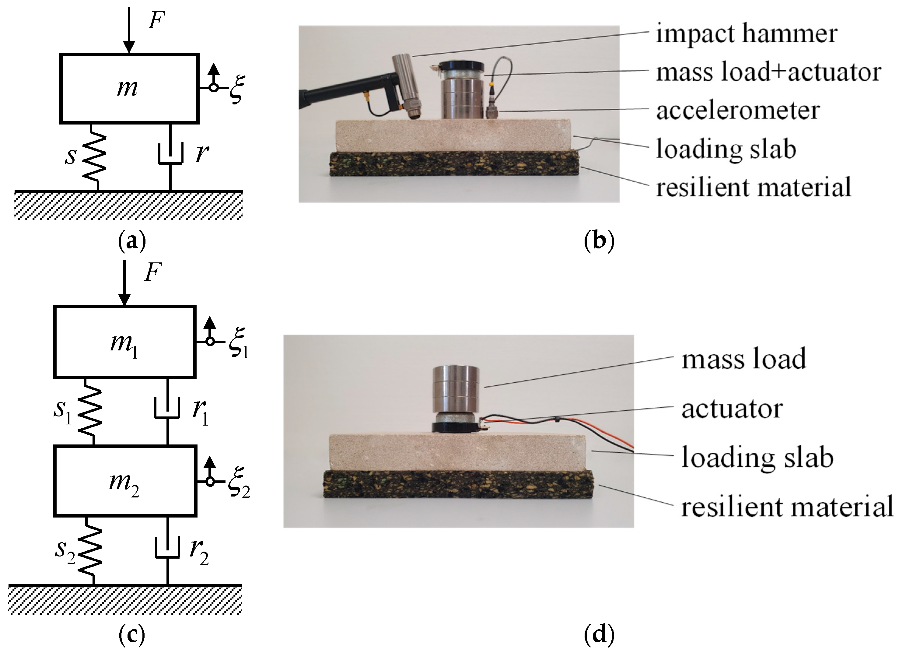
3.1. ISO 9052-1
3.2. Proposed Approach
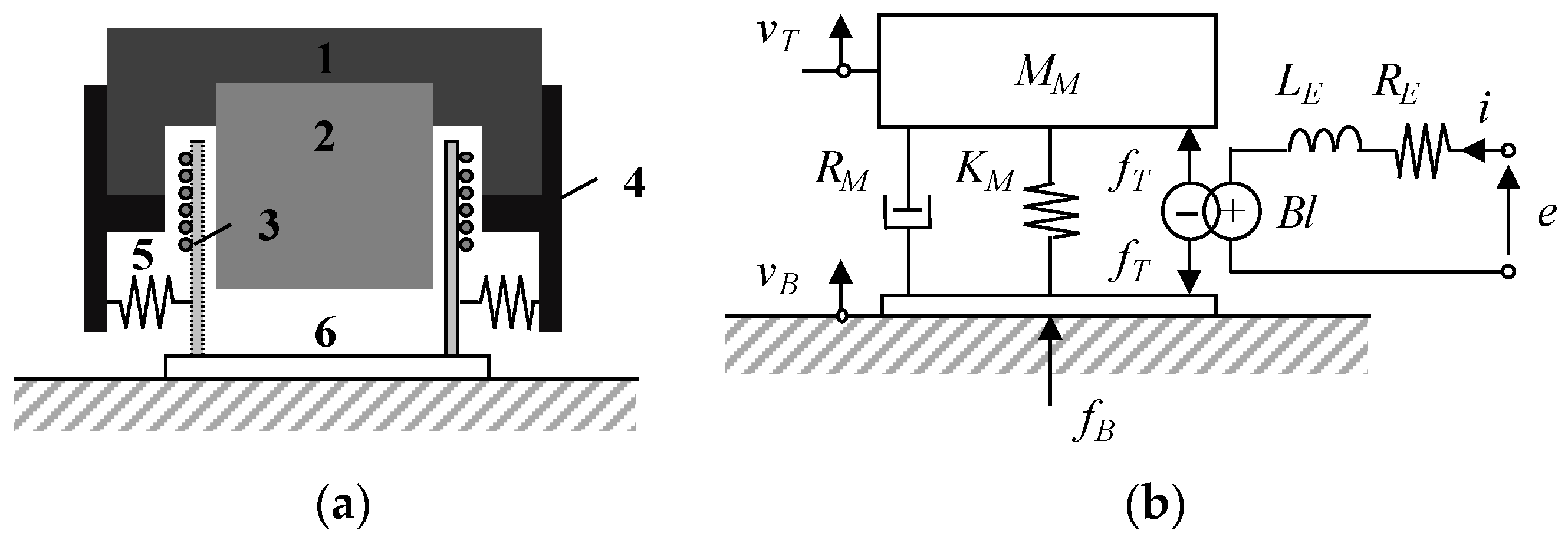
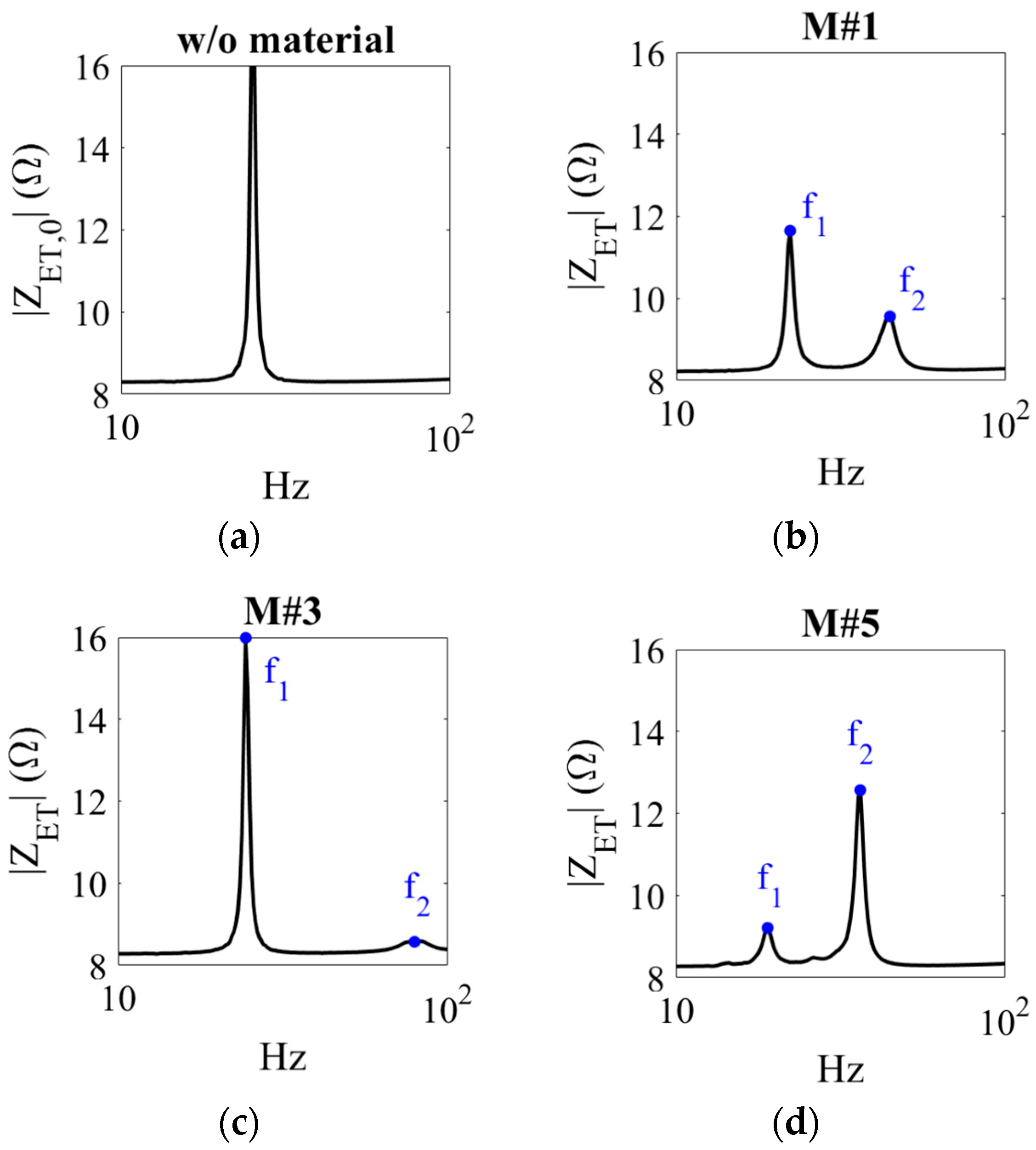
3.3. Electro-Mechanical Circuit Model
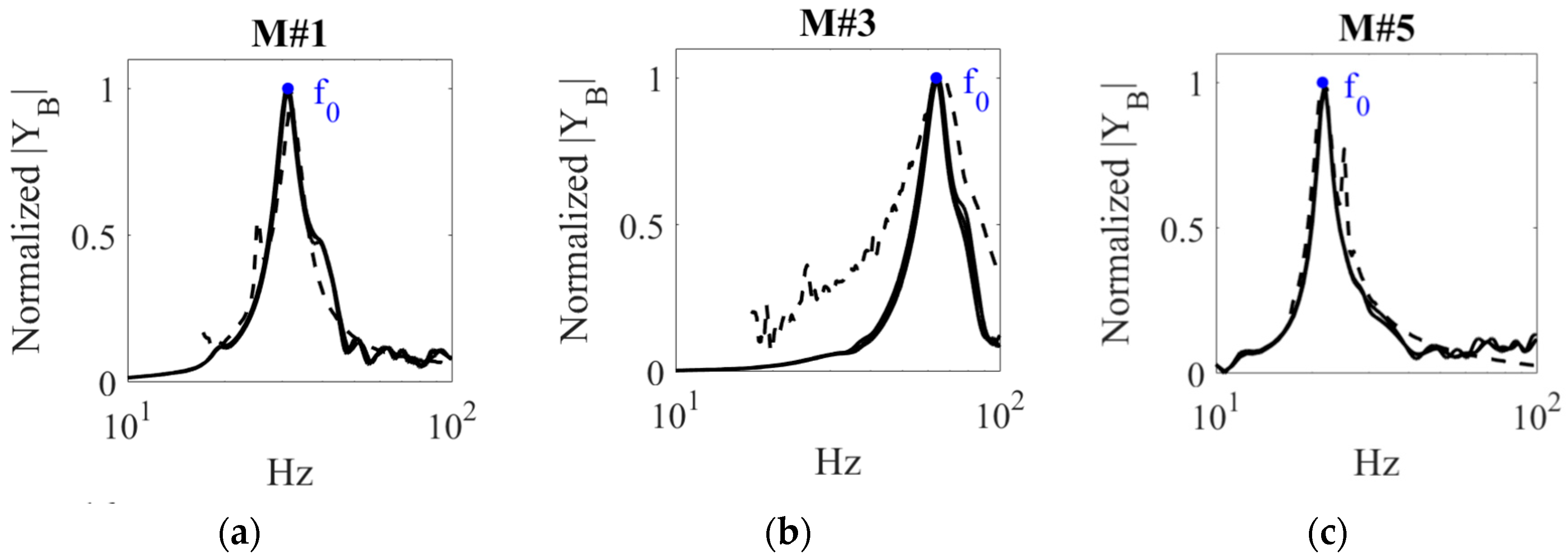
4. Results and Discussion
4.1. Proposed Approach vs. ISO 9052-1
4.2. Remarks on the Applicability of the Proposed Approach
5. Conclusions
Author Contributions
Funding
Institutional Review Board Statement
Informed Consent Statement
Data Availability Statement
Conflicts of Interest
References
- Rindel, J.H. Sound Insulation in Buildings; CRC Press: Boca Raton, FL, USA, 2018. [Google Scholar]
- Schiavi, A.; Pavoni, A.; Russo, F. Estimation of the acoustical performance of floating floors from dynamic stiffness of resilient layers. Build. Acoust. 2005, 12, 99–113. [Google Scholar] [CrossRef]
- ISO 9052-1; Acoustics. Determination of Dynamic Stiffness. Part 1: Materials Used under Floating Floors in Dwellings. International Organization for Standardization: Geneva, Switzerland, 1989.
- Schiavi, A.; Pavoni, A.; Corallo, M.; Russo, F. Acoustical performance characterization of resilient materials used under floating floors dwellings. Acta Acust. United Acust. 2007, 93, 477–485. [Google Scholar]
- Cremer, L.; Heckl, M.; Petersson, B.A.T. Structure Borne Sound; Springer: Berlin/Heidelberg, Germany, 2005. [Google Scholar]
- Urban, D.; Zat’ko, P.; Roozen, N.B.; Muellner, H.; Glorieux, C. On the uncertainty of dynamic stiffness measurements. J. Acoust. Soc. Am. 2017, 141, 3930. [Google Scholar]
- New Transducers Ltd. NXT Technology Review; New Transducers Ltd.: Cambridge, UK, 2002. [Google Scholar]
- Fuller, C.R.; Elliott, S.J.; Nelson, P.A. Active Control of Vibration; Academic Press: Cambridge, MA, USA, 1996. [Google Scholar]
- Paulitsch, C.; Gardonio, P.; Elliott, S.J. Active vibration control using an inertial actuator with internal damping. J. Acoust. Soc. Am. 2006, 119, 2131–3140. [Google Scholar] [CrossRef]
- Boulandet, R.; Pelletier, A.; Micheau, P.; Berry, A. Active Vibration Control Using Self-Sensing Actuators: An Experimental Comparison of Piezoelectric and Electromagnetic Technologies. In Proceedings of the ASME 2014 IMECE, Montreal, QC, Canada, 14–30 November 2014. [Google Scholar]
- Robin, O.; Chazot, J.D.; Boulandet, R.; Michau, M.; Berry, A.; Atalla, N. A plane and thin panel with representative simply supported boundary conditions for laboratory vibroacoustic tests. Acta Acust. United Acust. 2016, 102, 170–182. [Google Scholar] [CrossRef]
- Carbajo, J.; Poveda, P.; Segovia, E.; Rincón, E.; Ramis, J. Determination of dynamic elastic modulus of materials under a state of simple stresses by using electrodynamic actuators in beam-type mechanical elements. Mater. Lett. 2022, 320, 132383. [Google Scholar] [CrossRef]
- Alba, J.; Arenas, J.P.; del Rey, R.; Rodríguez, J.C. An electroacoustic method for measuring airflow resistivity of porous sound-absorbing materials. Appl. Acoust. 2019, 150, 132–137. [Google Scholar] [CrossRef]
- Marmaroli, P.; Allado, M.; Boulandet, R. Towards the detection and classification of indoor events using a loudspeaker. Appl. Acoust. 2023, 202, 109161. [Google Scholar] [CrossRef]
- Li, S.; Xu, G.; Jiang, C.; Hu, H. Determination of the dynamic modulus of elasticity of pine based on the PZT Transducer. Forests 2024, 15, 459. [Google Scholar] [CrossRef]
- Guidorzi, P.; Barbaresi, L.; Garai, M. Measuring the dynamic stiffness of resilient materials using EES and MLS signals. Appl. Acoust. 2018, 138, 92–100. [Google Scholar] [CrossRef]
- Leach, W.M., Jr. Impedance compensation networks for lossy voice-coil inductance of loudspeaker drivers. J. Audio Eng. Soc. 2004, 52, 358–365. [Google Scholar]
- Fahy, F.; Gardonio, P. Sound and Structural Vibration: Radiation, Transmission and Response; Academic Press: Cambridge, MA, USA, 2007. [Google Scholar]
- Beranek, L.L.; Mellow, T.J. Acoustics: Sound Fields and Transducers; Academic Press: Cambridge, MA, USA, 2012. [Google Scholar]
- ISO 7626-2; Mechanical Vibration and Shock. Experimental Determination of Mechanical Mobility. Part 2: Measurements Using Single-Point Translation Excitation with an Attached Vibration Exciter. International Organization for Standardization: Geneva, Switzerland, 2015.
- Segovia, E.; Torres, J.; Carbajo, J.; Ramis, J.; Arenas, J.P. Determination of the elastic parameters of a material from a standardized dynamic stiffness testing. J. Sound Vib. 2019, 460, 114885. [Google Scholar] [CrossRef]
- Xia, E.; Cao, Z.; Zhu, X.; Qiu, S.; Xue, Z.; He, H.; Li, L. A modified dynamic stiffness calculation method of rubber isolator considering frequency, amplitude and preload dependency and its application in transfer path analysis of vehicle bodies. Appl. Acoust. 2021, 175, 107780. [Google Scholar] [CrossRef]
- Arenas, J.P.; Sepulveda, L.F. Impact sound insulation of a lightweight laminated floor resting on a thin underlayment material above a concrete slab. J. Build Eng. 2022, 45, 103537. [Google Scholar] [CrossRef]
- Lee, J.-Y. Evaluation of the long-term sound reduction performance of resilient materials in floating floor systems. J. Sound Vib. 2016, 366, 199–210. [Google Scholar] [CrossRef]
- Wu, K.; Kuhlenkoetter, B. Experimental analysis of the dynamic stiffness in industrial robots. Appl. Sci. 2020, 10, 8332. [Google Scholar] [CrossRef]

| Sample ID | h (mm) | ρ (kg/m3) |
|---|---|---|
| M#1 | 20.16 | 97.97 |
| M#2 | 31.34 | 96.52 |
| M#3 | 20.96 | 156.25 |
| M#4 | 10.41 | 206.53 |
| M#5 | 40.62 | 59.70 |
| Parameter | Description | Value | Units |
|---|---|---|---|
| LE | Coil inductance | 1.0 | mH |
| MM | Mass of the actuator | 133 | g |
| RE | Coil resistance | 8.2 | ohms |
| Sample ID | SISO 9052-1 (MN/m3) | Sapproach (MN/m3) | Relative Error (%) |
|---|---|---|---|
| M#1 | 3.33 | 3.43 | 3.00 |
| M#2 | 3.20 | 3.25 | 1.56 |
| M#3 | 14.10 | 14.70 | 4.26 |
| M#4 | 29.93 | 29.28 | 2.17 |
| M#5 | 1.63 | 1.60 | 1.84 |
Disclaimer/Publisher’s Note: The statements, opinions and data contained in all publications are solely those of the individual author(s) and contributor(s) and not of MDPI and/or the editor(s). MDPI and/or the editor(s) disclaim responsibility for any injury to people or property resulting from any ideas, methods, instructions or products referred to in the content. |
© 2024 by the authors. Licensee MDPI, Basel, Switzerland. This article is an open access article distributed under the terms and conditions of the Creative Commons Attribution (CC BY) license (https://creativecommons.org/licenses/by/4.0/).
Share and Cite
Carbajo, J.; Poveda, P.; Segovia, E.; Prieto, A.; Río-Martín, L.; Pastor, J.D.; Ramis, J. An Alternative Approach to Determine the Dynamic Stiffness of Resilient Materials under Low Prestatic Load. Appl. Sci. 2024, 14, 4925. https://doi.org/10.3390/app14114925
Carbajo J, Poveda P, Segovia E, Prieto A, Río-Martín L, Pastor JD, Ramis J. An Alternative Approach to Determine the Dynamic Stiffness of Resilient Materials under Low Prestatic Load. Applied Sciences. 2024; 14(11):4925. https://doi.org/10.3390/app14114925
Chicago/Turabian StyleCarbajo, Jesús, Pedro Poveda, Enrique Segovia, Andrés Prieto, Laura Río-Martín, José Daniel Pastor, and Jaime Ramis. 2024. "An Alternative Approach to Determine the Dynamic Stiffness of Resilient Materials under Low Prestatic Load" Applied Sciences 14, no. 11: 4925. https://doi.org/10.3390/app14114925
APA StyleCarbajo, J., Poveda, P., Segovia, E., Prieto, A., Río-Martín, L., Pastor, J. D., & Ramis, J. (2024). An Alternative Approach to Determine the Dynamic Stiffness of Resilient Materials under Low Prestatic Load. Applied Sciences, 14(11), 4925. https://doi.org/10.3390/app14114925