1. Introduction
In maritime navigation, ships face a complex and variable physical environment, particularly the inevitable threat from various external impact loads such as waves, collisions, and explosions. With the continuous development of ship engineering technology and the diversification of ship missions, higher demands are placed on the ship’s impact resistance capabilities. The propulsion shaft system, as an essential component of the power system, plays a crucial role [
1]. When a ship is subjected to impact loads, the normal operation of the propulsion shaft system and its related components is vital to the reliability of the ship’s power system. The displacement response under impact loads and the vibration stress generated at the bearing supports are directly related to the survivability of the ship’s power system. The high-elasticity coupling is the most important vibration isolation and torque transmission device in the propulsion shaft system, and its impact resistance performance has a significant impact on the overall impact resistance performance of the ship’s propulsion shaft system. Currently, the standards for impact resistance calculations primarily refer to the United States Navy’s specifications for the impact resistance of shipborne equipment [
2] and the German Navy’s construction standards. Many research institutions and scholars are highly focused on the impact resistance research of propulsion equipment [
3]. Conducting simulation research on the impact resistance performance of the propulsion shafting system and high-elasticity couplings is of significant importance for evaluating the strength performance of the propulsion shafting system and for the optimization and improvement of the ship’s power system.
In the area of impact response analysis for ship propulsion shafting systems, extensive research has been conducted by scholars both domestically and internationally, yielding several research outcomes. There are three main methods for impact resistance analysis, namely equivalent statics, frequency-domain analysis, and time-domain analysis [
4,
5,
6].
The equivalent static method simplifies calculations by translating impact loads into equivalent static loads. This approach is often used to assess the response of structures under impact loads, especially when it is difficult to conduct actual dynamic load testing. However, this method only yields maximum stress and deformation results and is less commonly used in practical applications [
7].
The frequency-domain analysis method transforms the impact load into a frequency-domain representation to calculate the spectral distribution of the impact load at different frequencies. Based on modal analysis, it solves the dynamic response characteristics of the system at various frequencies. He et al. [
8] established a non-parametric dynamic model based on a test rig, and through experiments and numerical calculations, obtained the shaft system’s displacement response, thereby concluding that uncertainty has a significant impact on the dynamic characteristics of the shaft system. Liang et al. [
9], based on the response spectrum analysis method, combined with the design impact spectrum used by the U.S. Navy’s DDAM method, calculated and analyzed the impact response spectrum for the research objective of the article. They used the finite element method for calculation and analysis and took the cantilever beam explosion impact as an example to verify the reliability of the numerical method. Camargo F. [
10] systematically summarized various numerical simulation methods in the computational modeling of underwater explosions, focusing primarily on the characteristics of Eulerian and Lagrangian fluid descriptions, Johnson–Cook and Gurson constitutive materials for naval panels, and solving methods such as the Finite Element Method, Finite Volume Method, Boundary Element Method, and Smooth Particle Hydrodynamics. These methods were applied to assess different ship hull materials, with various mathematical approaches and experimental tests conducted for validation. Pang et al. [
11] took a certain launching ship as an example and proposed a test method for evaluating the response of the launching platform, as well as tested the maximum structural impact response under the launcher, which gradually attenuated to the bow and stern of the ship. The test analysis showed that the vibration acceleration response was different in different directions, with the highest response in the vertical direction and the lowest in the longitudinal direction. The test results were then verified through finite element numerical analysis. Zhu et al. [
12] established a coupled model of longitudinal vibration of the thrust shaft system, bearing lubrication, and shaft misalignment, and analyzed the dynamic characteristics of the stern bearing under explosive impact by solving the Reynolds equation and explosive impact equation. Liang et al. [
13] studied the impact of waves impacts on the water-lubricated bearings in the propulsion shaft system. By establishing a water-lubricated bearing model that combines the wave impact function, Reynolds equation, and Euler equation, they analyzed the impact of wave impact magnitude, direction, and entry time on the starting performance of the bearing. Long et al. [
14] employed the discrete element method to study the interaction between sea ice and offshore wind turbines, analyzing factors of brittle and ductile failure, and confirmed a strong correlation between self-excited vibration and the brittle–ductile failure of sea ice. Huang et al. [
15] investigated the response characteristics of the outer hull of a ship’s double-layer panel after being penetrated by an energetic metal jet and subjected to a secondary near-field explosion, using the Coupled Eulerian–Lagrangian method for numerical calculations and validated the analysis through experimental verification. Ley et al. [
16], based on strip theory, boundary element methods, and unsteady Reynolds-averaged Navier–Stokes equations, analyzed the wave load results obtained for different ship types under extreme wave motion using various computational methods. They systematically compared the results with experimental data, indicating that numerical methods based on potential theory are consistent with experimental results in small and moderate waves, but exhibit significant discrepancies with measurements in higher waves. Mannacio et al. [
17] took a specific simplified basic structure of a ship as an example and conducted numerical simulation calculations using the dynamic implicit finite element analysis method. Then, based on the MIL-S-901D medium-weight impact standard, they conducted impact tests on three different models. The test data obtained from the medium-weight, high-impact impact machine were compared with the test results to verify the effectiveness of the calculation method. Liu et al. [
18] used a nonlinear explicit dynamic analysis method, established a three-dimensional free-field impact wave numerical model, and studied the fatigue damage state of the plate-type explosion-proof door under the action of underwater explosion impact spectrum through finite element numerical simulation. Ni et al. [
19] utilized a one-way coupled Computational Fluid Dynamics–Discrete Element Method approach to construct a finite element model of a polar vessel, observing the propagation of ice cracks and analyzing the comparison between simulation results and previous experimental data. This study validated that during the ice-breaking process, the ice load excitation is significantly greater than the hydrodynamic resistance excitation. Cao et al. [
20] established an impact resistance numerical model of the hydraulic coupling, conducted impact response calculations on it using the DDAM method, analyzed the performance characteristics of the main components under different impact loads, and used orthogonal experiments to analyze the influencing factors. Paul et al. [
21] designed the isolation system for the U.S. Navy’s auxiliary turbine generator sets on ships. They used different simplified and complete system finite element models, selected specific elastic isolation installation seats, adjusted them through impact resistance test tests, and met the design requirements of the isolation system under the action of impact loads. Hu et al. [
22], based on typical multi/single-cargo hold asymmetric damage models, studied the water flooding characteristics of the compartment under dynamic explosion and conducted explosive impact calculations under time-domain conditions. Kwak et al. [
23] proposed a method for analyzing the degree of structural fatigue damage under explosive impact, calculated the structural damage degree based on physical design parameters and accurate analysis results, and used it for the design structure configuration assessment of naval ships. The FLACS commercial program was used for verification. Xie et al. [
24], based on the dynamic design analysis method, conducted impact response calculations for a gas turbine simplified to a system with two degrees of freedom and analyzed the impact displacement response and impact stress response of key components such as the flexible bracket. Rakotomalala et al. [
25] established a semi-analytical model of the ship impact system and used the model to calculate the dynamic response of the submarine hull under the action of underwater explosion-induced pressure, derived simple mathematical expressions, and thus obtained the impact of non-contact explosions on the ship’s hull and equipment. Cui et al. [
26] took the propulsion shaft system with an elastic coupling as an example, established its finite element model, and conducted impact calculations on the propulsion shaft system and high-elasticity coupling based on the DDAM method and time-history method, and analyzed its impact resistance performance.
The time-domain analysis method investigates the dynamic response of a system as it changes over time under the influence of impact loads. It is suitable for calculating the dynamic characteristics of complex structures, such as propulsion shafting systems, under transient load conditions. However, compared to the frequency-domain method, it consumes more computational resources and is more complex than both the frequency-domain method and the equivalent static method. Kim et al. [
27], based on the German Navy standard, used numerical analysis methods to conduct time-domain transient response calculations on gas turbine units under non-contact underwater explosions and analyzed the impact load on key components for structural safety performance assessment. Yang et al. [
28] established a finite element model of the propulsion shaft system with or without coupling in the longitudinal and torsional directions, applied a double triangular wave impact load in the longitudinal and torsional directions using the time-domain simulation method, and the coupled system of torsion and longitudinal displacement made the longitudinal displacement increase rapidly and then gradually decrease to 0 under the action of damping, and the torque vibration of the shaft section was consistent with the displacement form. Wang et al. [
29], based on the transfer matrix-Newmark step-by-step integration method, used the transfer vector instead of the traditional vector, analyzed the time-domain dynamic response of the propulsion shaft system under impact loads, and studied the impact of initial stress on the response. Küçükarslan S. [
30] used the mixed boundary element method, modeled the pile with finite elements, solved the control equation using the implicit integration method, and applied the displacement balance condition at each time analysis step to conduct time-domain transient analysis of the pile under impact loads. Liu et al. [
31] employed a bidirectional coupling approach to discuss the impact of structural flexibility on the slamming phenomenon of wedge-shaped bodies and ship models. The effectiveness of the numerical method used was validated through the consistency between the simulation results and experimental data. Zhao et al. [
32] proposed a time-domain decomposition method for multiple impact signals of the crankshaft impact as an example, adjusted the design parameters to make it adaptively adjustable, and accurately identified the impact number and impact effect of the vibration signal. Zhu et al. [
33] have developed an analytical approach to forecast the elastic dynamic response of a rectangular plate subjected to the influence of moving pressure impact loads. The methodology incorporates a dynamic load coefficient to scrutinize the influence of moving velocity on dynamic loads. After the model-based analysis, the authors delineated the expression for the DMLC and advanced an empirical formula for the conversion of moving impact loads into an equivalent static load representation. Piscopo et al. [
34] based on a nonlinear time-domain hydrodynamic model, compared the results obtained through the time-domain analysis method and the spectral analysis under the Welch and Thomson method. The results indicated that spectral analysis is conducive to enhancing the assessment of the fatigue life of mooring lines. Wang et al. [
35] used the seakeeping method, computational fluid dynamics method, and the finite element method to simulate the slamming pressure and local structural response of a large container ship and analyzed the dynamic characteristics of the bow-shaped structure under slamming load. Zhang et al. [
36] employed the time-domain method to study the interaction between sea ice and the cable tunnel structure of offshore substations, analyzing the failure patterns of sea ice and the variation rules of ice force amplitudes under ice loads. Zhao et al. [
37] proposed a model for an icebreaker colliding with an ice ridge, determined the ice-induced forces on the hull based on numerical simulation, applied ice impact loads to the hull using a triangular pulse, and calculated the response characteristics of the structural model. Wang et al. [
38] proposed a numerical simulation method for calculating the ice resistance of cylindrical structures based on the discrete element method. By comparing the structural resistance results of model simulation under experimental conditions with the results of model experiments, the effectiveness of the numerical method was validated. Chung et al. [
39] took a high-speed catamaran as an example, conducted impact modeling of the catamaran ship type and fluid model based on the finite element method, proposed an impact resistance analysis method for high-speed catamaran ship types and discussed related influencing parameters, and finally compared the simulation results with empirical data for analysis. Sigrist et al. [
40] proposed a universal method for analyzing the dynamic response of underwater impact loads on ship equipment without the need for ‘coupled calculations’. Based on the calculation of transfer functions of fluid, structure, and structure coupling, the impact resistance performance of the ship’s hull and equipment was analyzed. Iakovlev et al. [
41,
42] studied a system composed of a fluid-filled underwater cylindrical shell and a rigid cylinder, where the fluid dynamic field was affected by an external shock wave, analyzed various phenomena of shock wave propagation and reflection, and the impact of the mass size of the core on the interaction between fluid and structure.
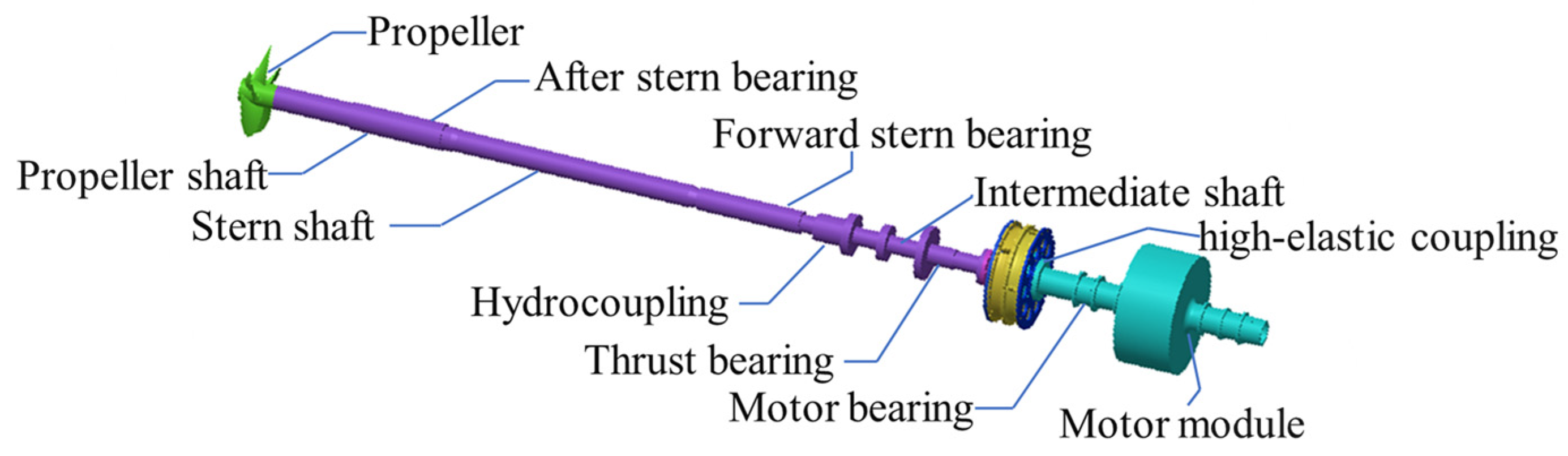
From the current state of research, it is evident that the impact resistance calculations for marine propulsion shafting systems primarily focus on calculations from the propeller to the thrust bearing, with almost no attention given to impact calculations for shafting systems containing high-elasticity couplings. Additionally, current research on high-elasticity couplings mainly revolves around the simulation and experimental computation of the couplings’ performance parameters, including radial stiffness and torsional stiffness. There is a notable lack of research and calculations on the impact characteristics simulation models of high-elasticity couplings. This paper aims to address the existing issues in the impact calculation and analysis of propulsion shafting systems containing high-elasticity couplings, thereby further perfecting the modeling methods for impact calculations, analysis of influencing factors, and other related theoretical issues. The arrangement of the research content of this paper is as follows:
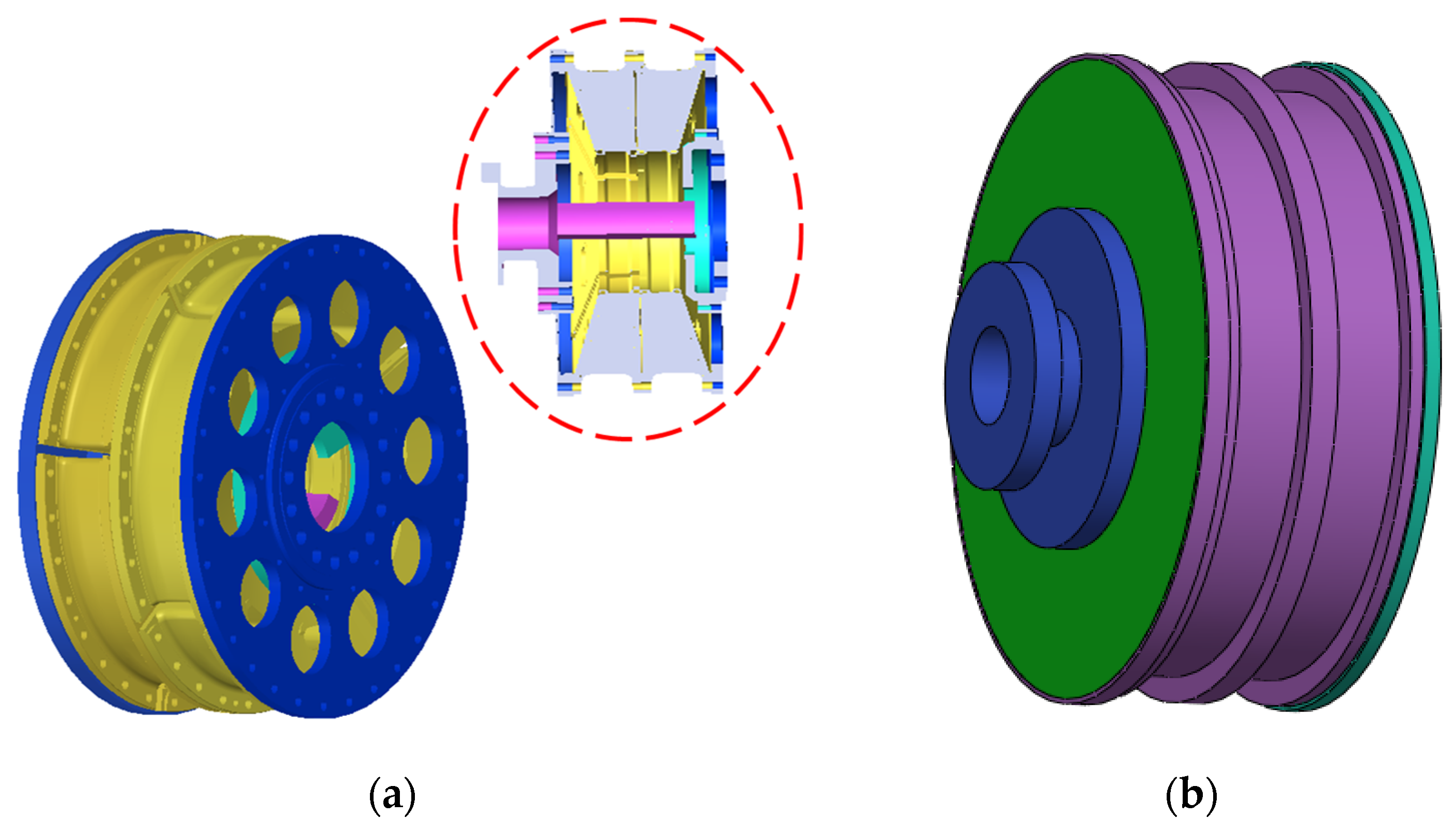
Section 2 will conduct a model study on the electric propulsion shafting system and high-elasticity coupling, providing a detailed description of the mechanical properties of the rubber material of the high-elasticity coupling, and performing static and modal analysis based on the established model of the electric propulsion shafting system;
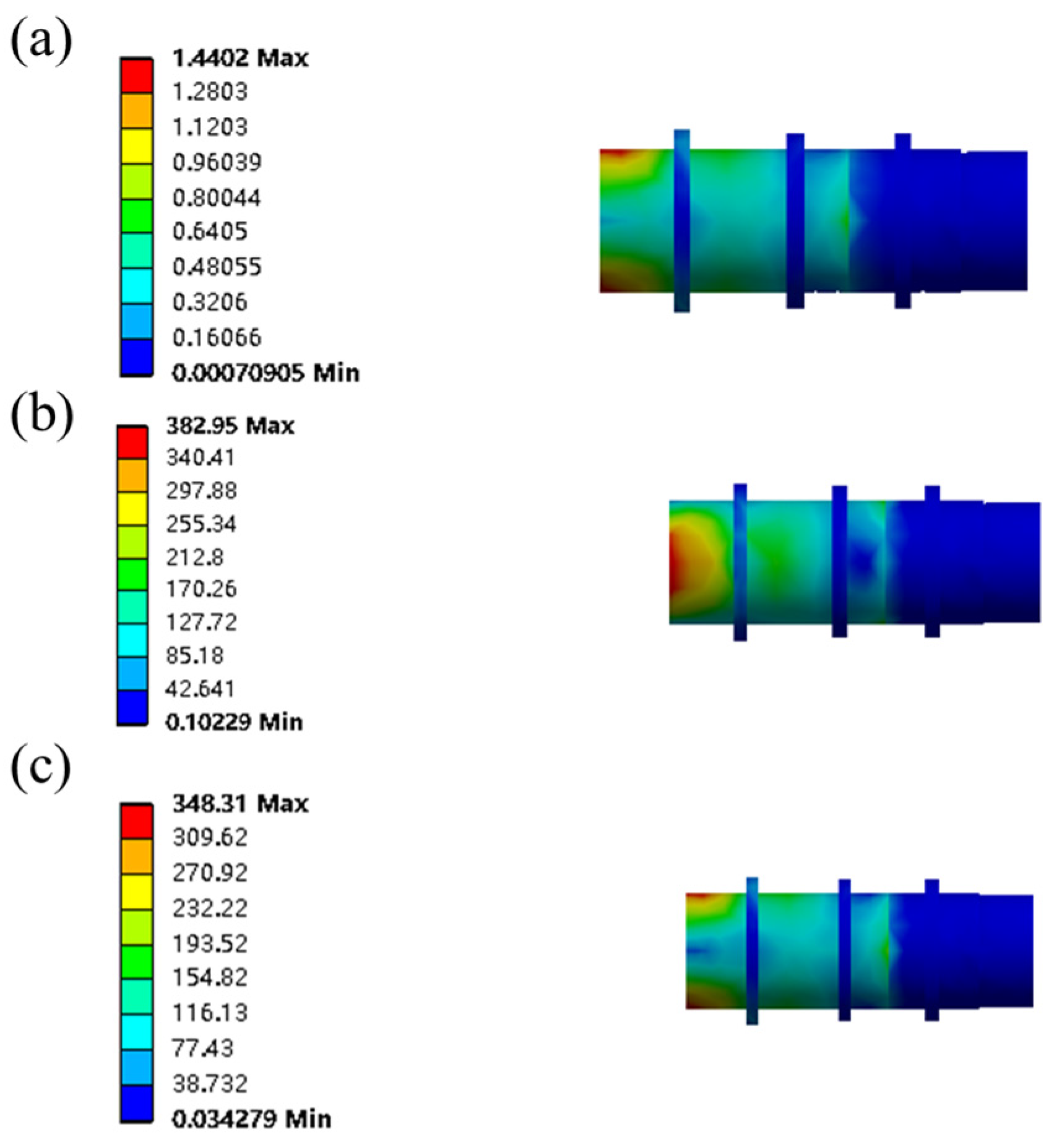
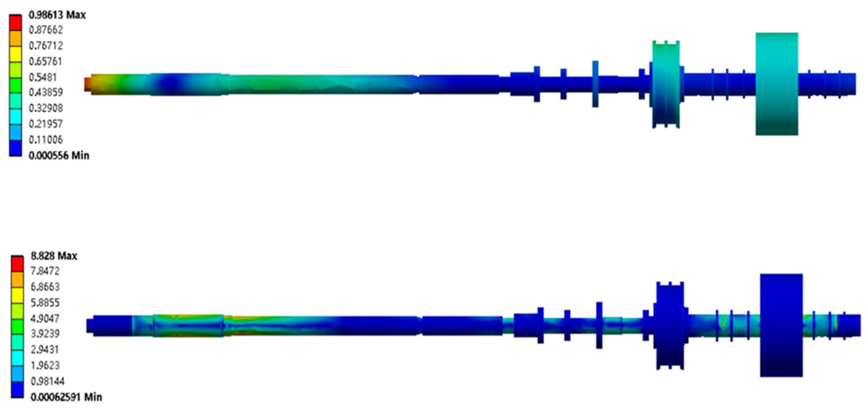
Section 3 will calculate the design impact acceleration based on the Dynamic Design Analysis Method (DDAM), and then analyze the impact response of the shafting system shaft segments and critical cross-sections under the action of impact loads;
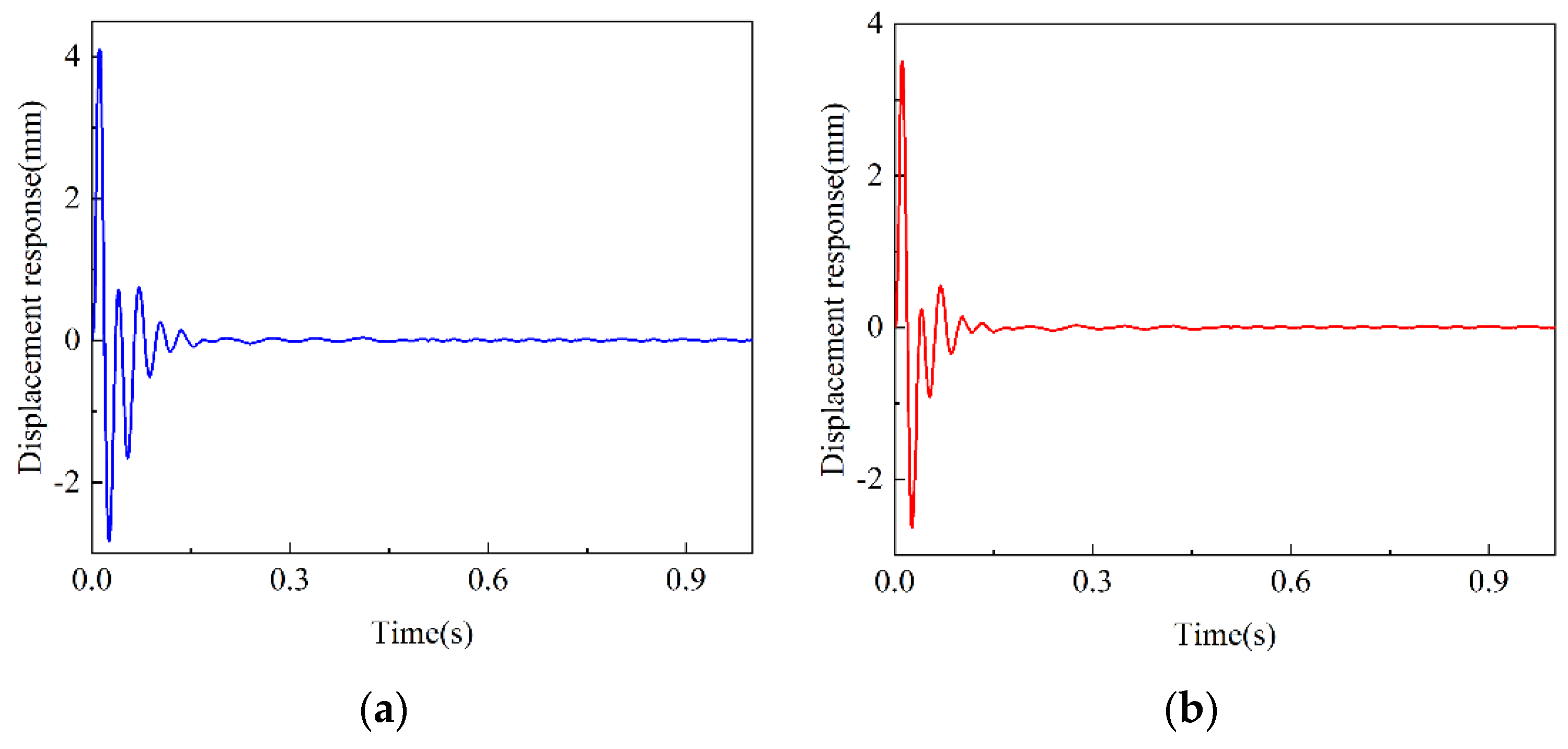
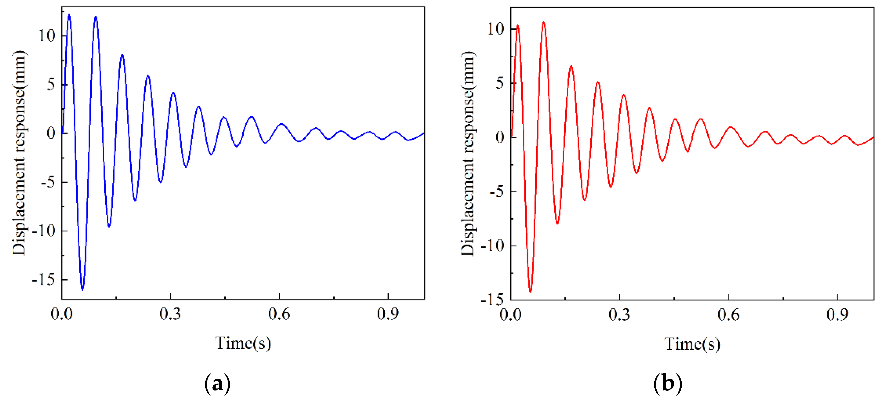
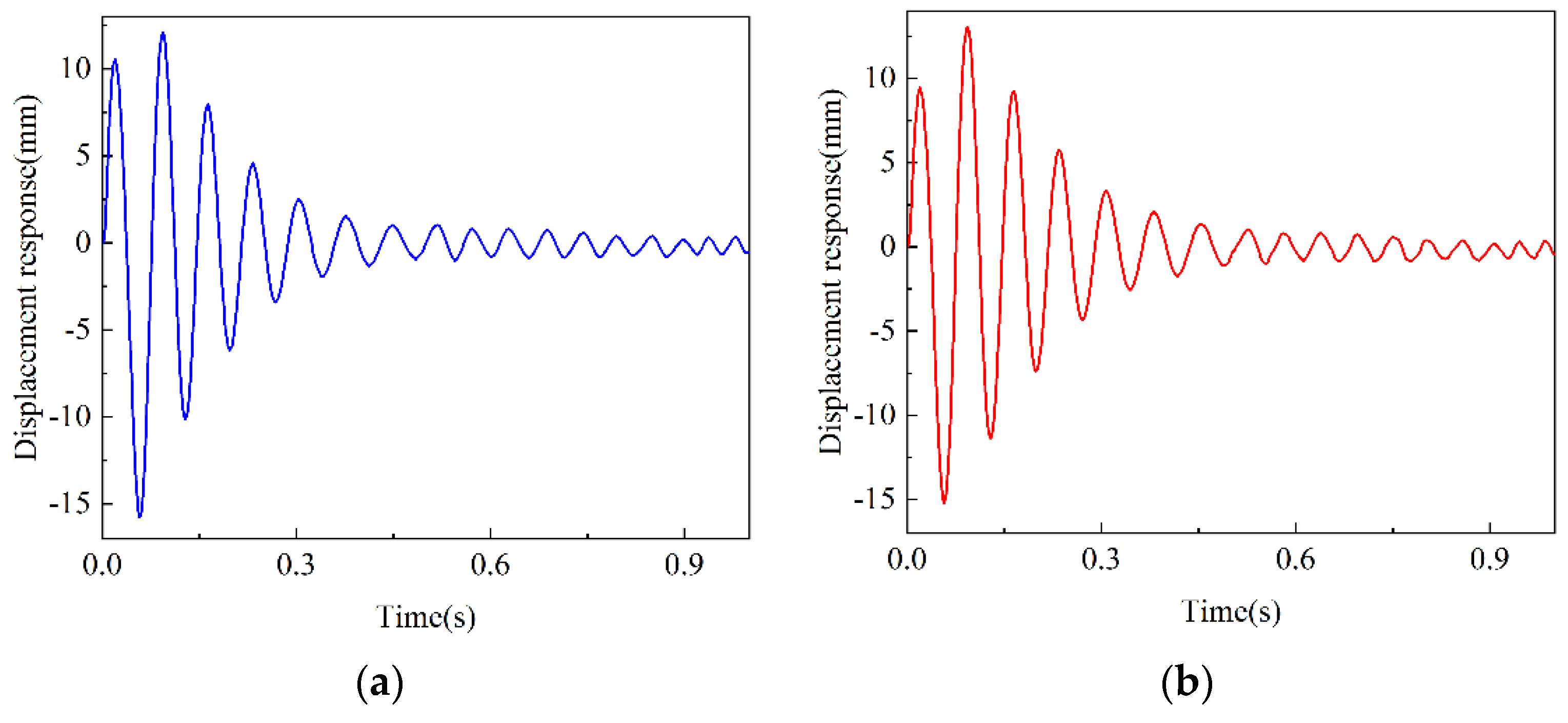
Section 4 will use the time-history method to calculate the impact spectrum, focusing on the analysis of the impact displacement response at the cross-section; Finally, in
Section 5, the conclusions will be drawn based on the aforementioned analyses.
6. Conclusions
This paper presents a case study of an electric propulsion shaft system, establishing a finite element model that includes an equivalent model of a high-elasticity coupling for the propulsion shaft system. The impact resistance performance is simulated using both the DDAM method and the time-history method. Through the analysis of the computational results, the following conclusions are drawn:
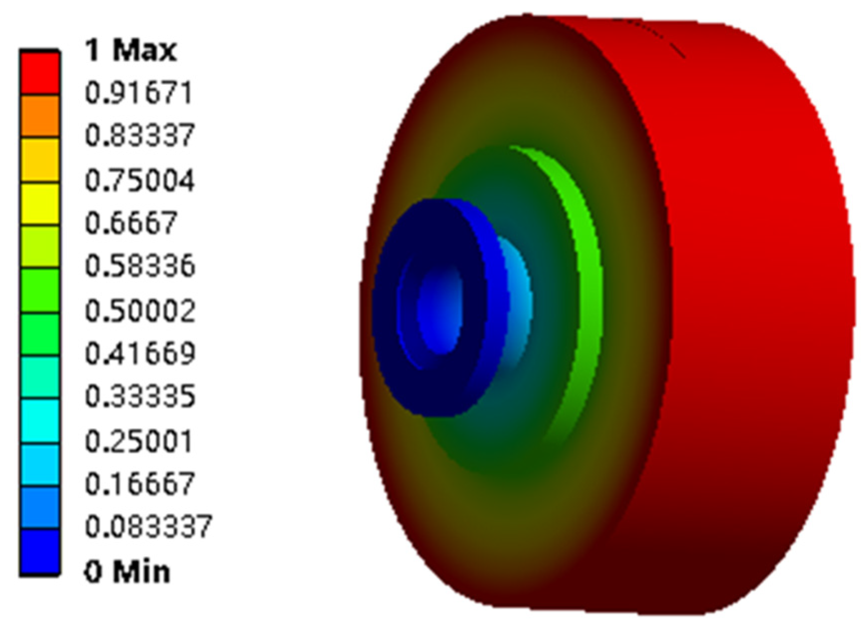
(a) Simulation calculations of the impact resistance for a finite element model of a propulsion shafting system containing an equivalent model of a high-elasticity coupling using different computational methods indicate that the equivalent model is convenient for modeling and has a higher computational speed, which allows for rapid forecasting of the impact resistance characteristics of a propulsion shafting system containing a high-elasticity coupling.
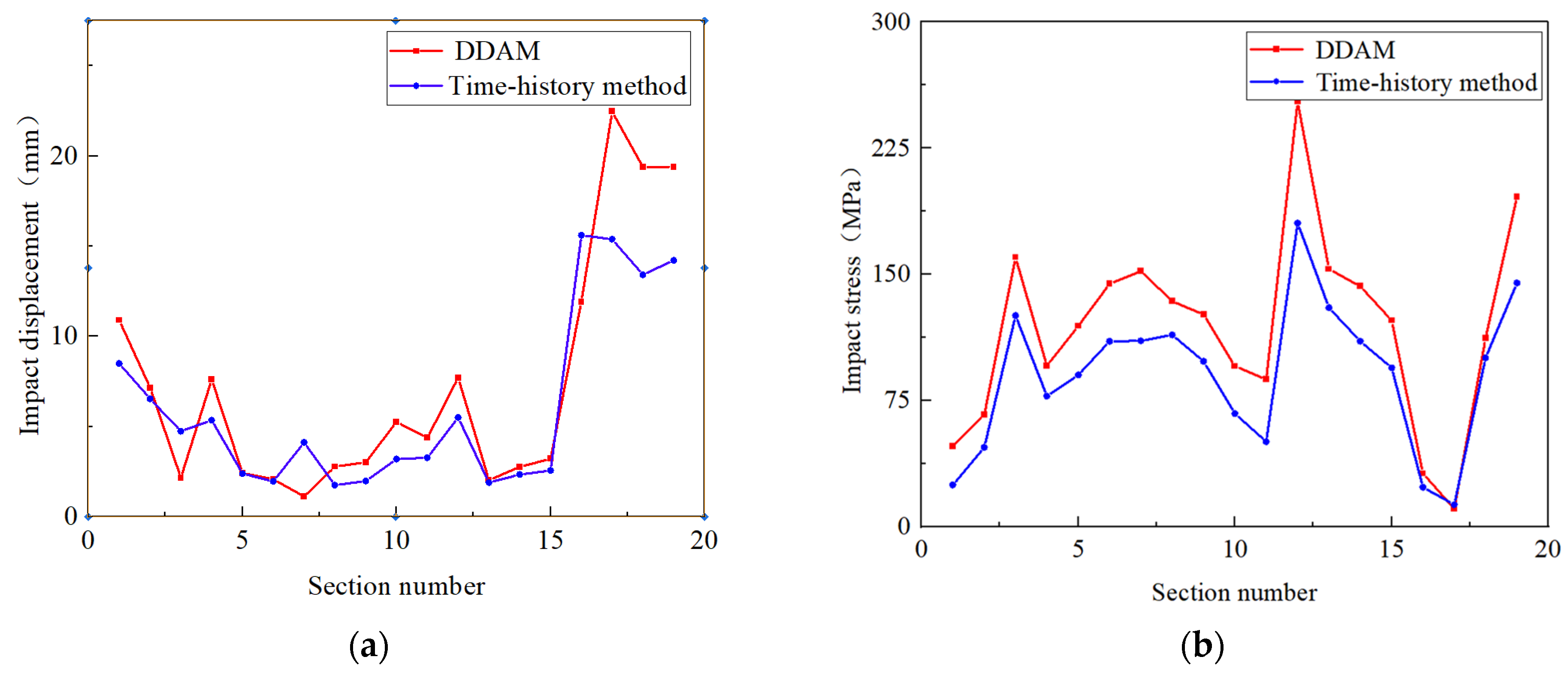
(b) Comparative analysis of the impact resistance simulation results for a ship’s electric propulsion shafting system containing a high-elasticity coupling using the Dynamic Design Analysis Method (DDAM) and the time-history method demonstrates the accuracy of the established equivalent model of the high-elasticity coupling.
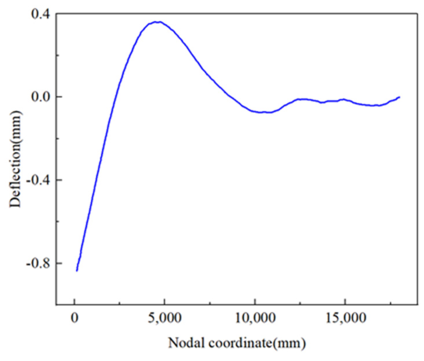
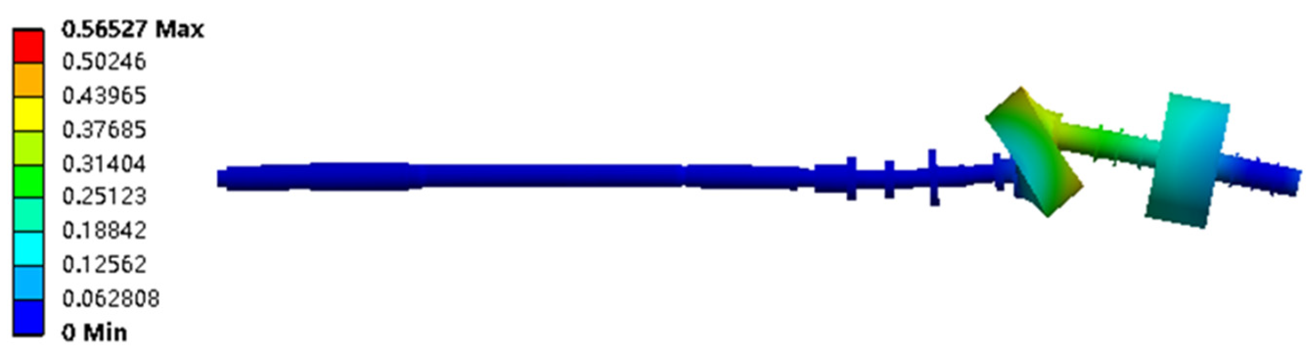
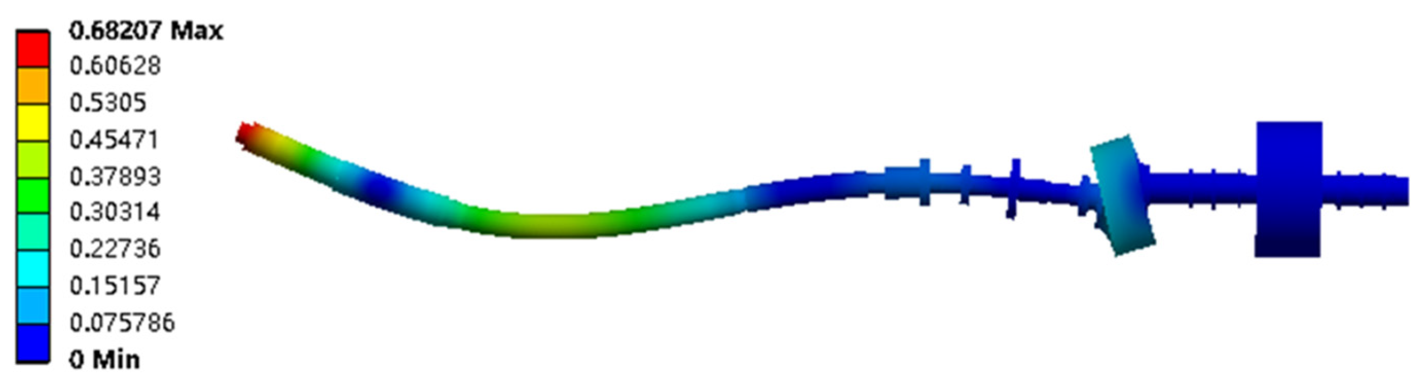
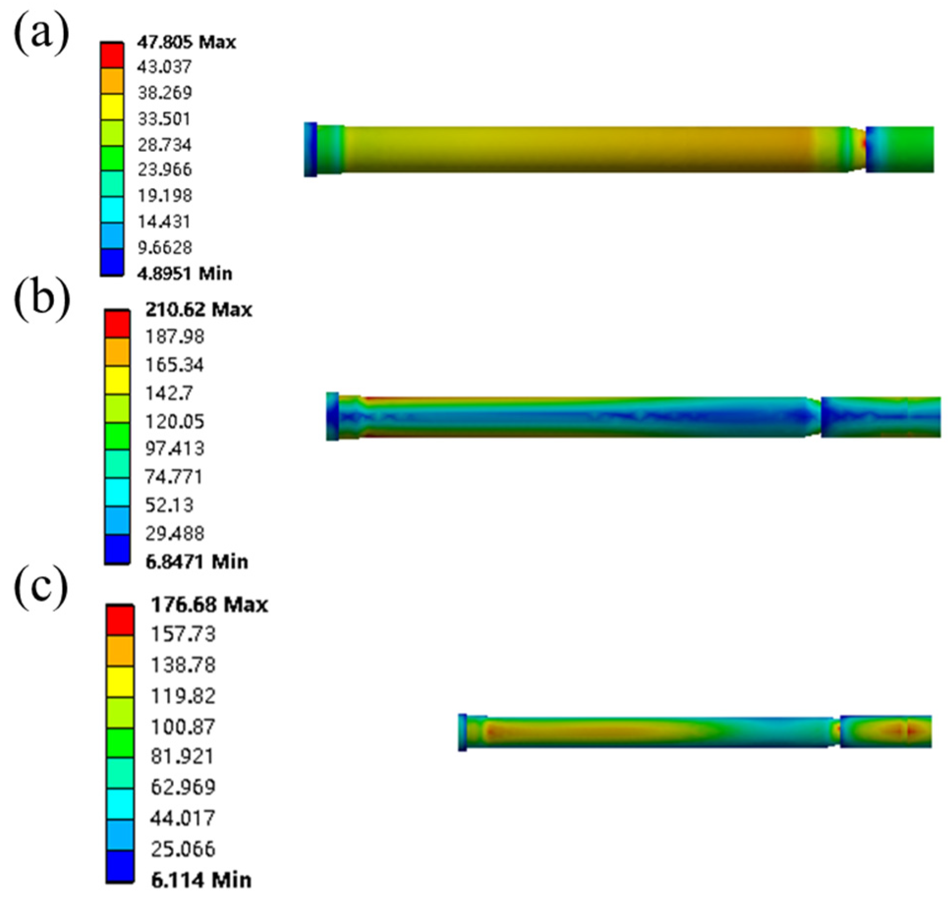
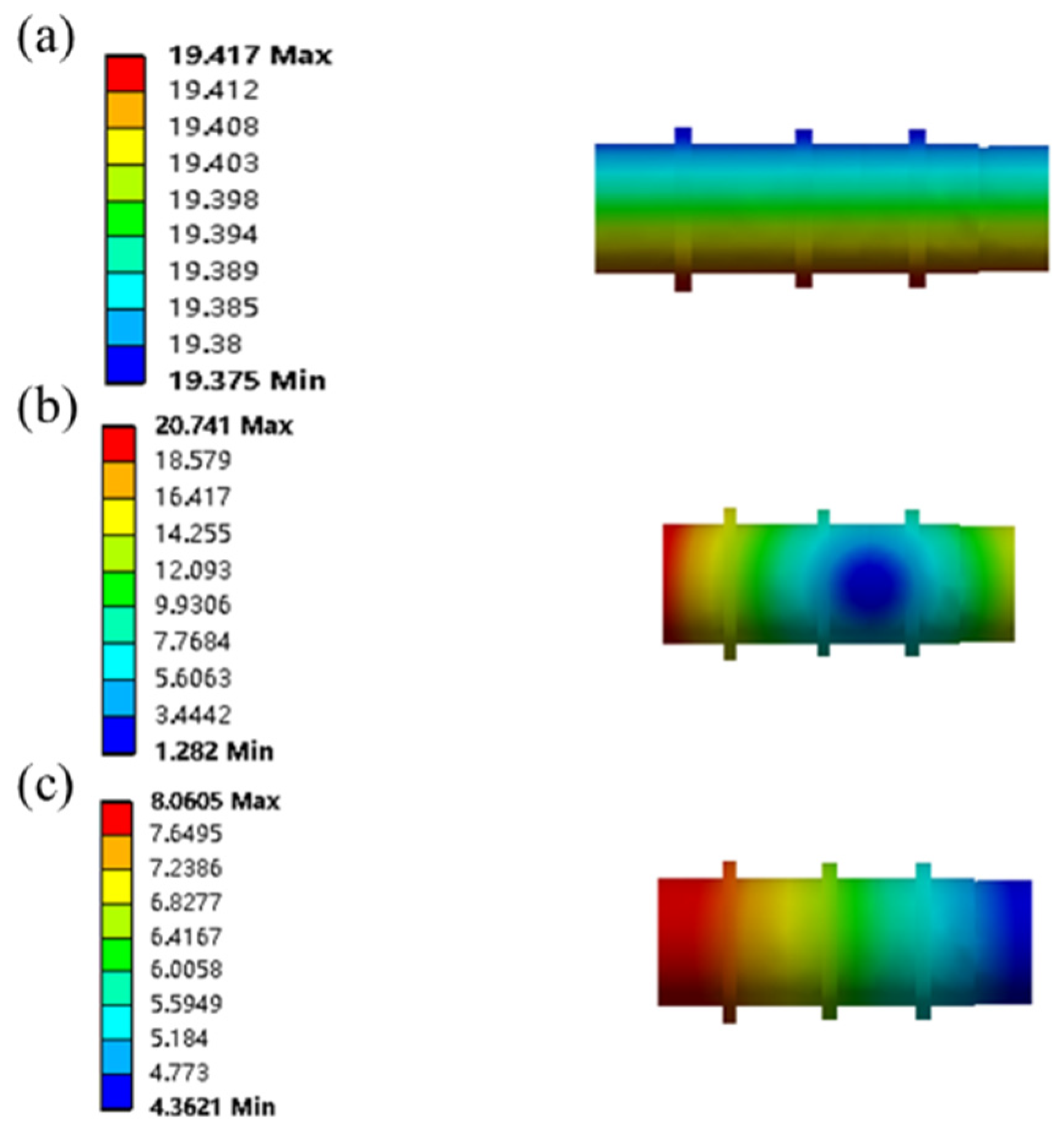
(c) Comparison of the impact resistance calculation results between DDAM and the time-history method reveals that the maximum impact displacement calculated by DDAM is 22.47 mm, occurring at the driven end of the high-elasticity coupling, and the maximum impact stress is 252.67 MPa, occurring at the thrust bearing support point. The time-history method calculates a maximum impact displacement of 15.61 mm, also at the driven end of the high-elasticity coupling, while the maximum impact stress is 180.45 MPa, occurring at the thrust bearing support point. The impact response results from the DDAM method are relatively larger, and the calculations tend to be conservative.
(d) Based on the impact resistance calculations for the propulsion shafting system using DDAM and the time-history method, the impact displacement of the high-elasticity coupling is less than its radial displacement compensation range (±24 mm); the impact stress of each shaft section is much lower than the allowable stress of the shaft section, which is 530 MPa. This indicates that the electric propulsion shafting system containing the high-elasticity coupling can safely operate under this impact load.
(e) Through the application of diverse methodologies in the investigation of the impact resistance performance of electric propulsion shaft systems incorporating high-elastic couplings, this research has furnished both the empirical data and theoretical underpinnings for the future design selection and predictive modeling of impact resistance for a variety of shaft systems and high-elastic couplings with distinct structural configurations.


