Article

Optimization of Uplift Piles for a Base Plate Considering Local Anti-Floating Stability

1
The Third Construction Engineering Company LTD. of China Construction Second Engineering Bureau, Beijing 100070, China
2
Key Laboratory of Urban Security and Disaster Engineering, Ministry of Education, Beijing University of Technology, Beijing 100124, China
*
Author to whom correspondence should be addressed.
Appl. Sci. 2024, 14(12), 5000; https://doi.org/10.3390/app14125000
Submission received: 10 April 2024 / Revised: 1 June 2024 / Accepted: 3 June 2024 / Published: 7 June 2024

Abstract

:
This paper focuses on the optimization of uplift piles for a base plate considering local anti-floating stability. According to the force characteristics of the base plate subjected to buoyancy, a bi-directional evolutionary structural optimization (BESO) process is proposed. The optimization process takes the pile length as the design variable and the pile end displacement as the sensitive coefficient. The proposed process is conducted with FLAC3D to optimize the length of each uplift pile, including two cases with different pile diameters and spacing. The optimization process shows that the deformation degree of the base plate is significantly reduced when the piles are adopted with large diameters and sparse spacing, and oscillates at a low level when the piles are adopted with small diameters and dense spacing. Consequently, the design method of uplift piles considering the local anti-floating stability is proposed by referring to the optimization results of two cases. Finally, the proposed design method is applied to a practical project, and the original design of the uplift piles is optimized. The comparison results show that the deformation degree of the base plate of optimization designs is significantly lower than the original design.

1. Introduction

With the development of underground space due to human activity, many underground structures have been buried increasingly deeper. Moreover, increasing groundwater levels have been observed in major cities all around the world due to water resources conservation policies. Many underground structures are subjected to high buoyancy nowadays, and the issue of anti-floating should be considered seriously in structure design and project construction [1,2,3,4,5,6,7,8,9]. Usually, anti-floating measures are divided into active anti-floating measures and passive anti-floating measures. Active anti-floating measures reduce the hydraulic head at the base plate by means of drainage. Passive anti-floating measures resist buoyancy by increasing the weight of structures or setting uplift piles (anchors) [1,10]. Among those anti-floating measures, uplift piles are widely used in various structures due to their advantages of convenient construction, long service life, and good economic benefits [11,12,13]. Figure 1 shows uplift piles used as anti-floating measures for an underground structure. Uplift piles provide pulling forces to offset buoyancy. In order to improve the mechanical performance of the uplift piles, most researchers focus on enhancing the ultimate pulling force of the pile by changing the pile structure. These piles include root piles, screw piles, belled piles, etc. [13,14,15,16,17,18,19,20,21]. Higher buoyancy can be resisted by setting these special piles. Most of the abovementioned research focuses on the overall anti-floating stability of underground structures. However, under the influence of multiple forces (buoyancy, pulling force, and column loads), the base plate will generate a large deformation and increase the risk of failure, which is the issue of local anti-floating stability. The design parameters of uplift piles include pile length, pile diameter, and pile spacing. Most of the current designs use the overall anti-floating stability as the verification condition, and arranged the pile according to equal length, equal diameter, and uniform distribution. It is clear that, this design method ignores the local anti-floating stability.
For the anti-floating design of the structure, in addition to satisfying the overall stability, the local anti-floating stability of the base plate should also be considered. Therefore, it is necessary to study the reasonable design parameters of uplift piles, so that the deformation degree of the base plate can be reduced under the premise of satisfying the overall anti-floating stability. In recent years, with the development of a soft computing technique, topology optimization theory has been widely used in geotechnical engineering, which provides new ways to solve traditional problems and provides the reference for structural design [22,23,24,25]. Topological optimization theory refers to finding the optimal distribution form of materials in the design domain under specific constraints. The bi-direction evolutionary structural optimization (BESO) method is one of the topological optimization methods. The basic principle of the BESO method is to discretize the structures into finite elements, add materials to the elements with high sensitivity, and remove materials from the elements with low sensitivity. Due to its concise theory and high efficiency combined with numerical calculation, the BESO method has been widely used in searching for the optimal layouts of structures. Liu et al. [17] combined the method with the limit equilibrium method to predict the critical failure surface of the anti-dip bedding rock slope. Nguyen et al. [19] used this method for reinforcement design around the tunnel. Tang [26] used finite element software ANSYS and wrote a BESO topology optimization program using APDL language to propose a bridge shape that satisfies functionality, economy, environmental protection, and aesthetics. Jing [27] used the topology optimization function that came with the ANSYS software to design the layout of the internal support of the foundation pit row piles by writing a program, which successfully realized the application of topology optimization to the optimal design of the foundation pit. Wang et al. [28] proposed a design method combining topology optimization and conceptual design of steel frame structures, which was verified to be highly efficient through the case studies examined. Zhang et al. [29] conducted a study on topology optimization algorithms applied to the design of concrete structural engineering to address the difficulties of design methods for reinforced concrete components. Liu et al. [30] optimized the design of H-beam web sections based on the continuum structure topology optimization variable density method with structural strain energy minimization as the optimization objective. Fang [31] established a mathematical model with material cost as the objective function, based on the topology optimization method of BESO algorithm, and proposed a set of economical design methods for the internal support of foundation pit row piles. Similar to the optimal layouts of structures, the purpose of optimizing the uplift piles is to minimize the deformation degree of the base plate by changing the distribution form of piles, including the pile length, pile diameter, and pile spacing.
In summary, it is feasible to use the BESO method to study the optimization of uplift piles for the base plate considering local anti-floating stability. In the present work, a BESO process with the pile length as the design variable and the pile end displacement as the sensitive coefficient is proposed. It is used for optimizing the distribution of pile lengths and reducing the deformation degree of the base plate. Two cases with different pile diameters and spacing are optimized, respectively. By comparing the optimization results of two cases, a design method of uplift piles considering the local anti-floating stability for the base plate is proposed. Finally, the proposed design is applied to an actual project, and the original design is optimized.

2. Optimization Method

2.1. Problem Description

Figure 2 shows the force analysis of the base plate. Water buoyancy and earth pressures are Pw and Ps, respectively. The pulling force provided by each uplift pile is Fpi. The column loads of the superstructure is FN. The base plate will generate differential deformation under multiple forces. The deformation degree of the base plate can be measured by its total strain energy C. Strain energy is the energy stored due to deformation, and it is potential energy that reflects the degree of deformation. From the aspect of improving the local anti-floating stability of the base plate, the optimization goal is as follows: under the constraint conditions, strain energy C is as small as possible by changing the design parameters of the uplift piles. Therefore, strain energy C can be used as the optimization objective function in the BESO method and expressed as follows:
C = f int d u
where fint is the internal force vector acting on the base plate element, and u is the displacement vector of the base plate element.
The BESO process in this study is based on the following assumptions. The soil is homogeneous and isotropic. Liquid–solid coupling is not considered. The pile is assumed to be a rigid body. The frictional resistance on the pile side varies linearly with the length of the pile.

2.2. Design Variable and Sensitivity Coefficient

In the BESO method, the design variable affects the change of the objective function. Therefore, it is necessary to use an appropriate design variable to minimize the objective function.
The pulling force Fpi is mainly provided by the lateral friction resistance of the pile side and the pile weight. Under the assumption that friction resistance varies linearly with the pile length, Fpi can be expressed as follows:
F p i = 2 π r 2 L i ρ g + λ q s k π D L i
where r is the radius of the pile, ρ is the material density, D is the pile diameter, Li is the pile length, λ is the reduction coefficient, and qsk is the standard value of the limited lateral resistance of the pile. According to Equation (2), under the conditions of the same soil layer and the pile diameter, Fpi can be expressed as a single-valued function of Li, namely
F p i = f 1 L i
According to Figure 2, under the specific site condition, the pulling force Fpi and earth pressure ps change with the different design parameters of uplift piles among the multiple forces. Furthermore, ps varies with i = 1 n F p i . Therefore, Fpi is the only variable that affects the external force of the base plate element, namely
f = i = 1 n f 2 F p i
where f is the external force vector acting on the base plate element. The numerical calculation is a process that the internal force and external force of the base plate elements are gradually balanced, and the residual force tends to zero, namely
R = f f int = 0
where R is the residual force vector. Combining with Equations (1) and (3)–(5), we obtain
C = i = 1 n f L i d u
It is inferred from Equation (6) that Li affects the strain energy C. Therefore, when other parameters are kept unchanged, Li can be used as the design variable of the BESO method to reduce the deformation degree of the base plate.
In the BESO method, the sensitivity coefficient α needs to be introduced, which controls the variation in the design variable (i.e., Li in this paper). In order to minimize the deformation of the base plate, which is subjected to buoyancy, each uplift pile under the base plate is required to generate approximately the same vertical displacements. If the vertical displacement of some piles is large, it is implied that the anti-floating force provided by these piles is relatively insufficient (i.e., Fpi is relatively insufficient). On the contrary, if the vertical displacement of some piles is much smaller than other piles, the Fpi of these piles should be reduced. Therefore, the vertical displacement of the single pile can be used as the indicator to determine whether the Fpi provided by this pile is reasonable. At the same time, Equation (2) shows that Fpi is only related to Li, and Li is the design variable in this paper. Therefore, the vertical displacement of the single pile can be used as the indicator to determine whether the pile length Li is reasonable, that is, as the sensitivity coefficient to control the variation in Li. Furthermore, according to the assumption that the pile is a rigid body, the displacement of the pile end can be regarded as the displacement of the pile and can be used as the sensitivity coefficient α.

2.3. BESO Process

Initially, the BESO process takes all uplift piles as the design domain and discretizes the piles into pile elements, which is the step of establishing the numerical model and meshing the model. Pile length Li is taken as the design variable, and the displacement of the pile end is the sensitivity coefficient. The constraints are considered in two aspects, as follows. i. Stability constraints: The structure meets the overall anti-floating stability requirements. ii. Volume constraints: The target total volume of piles after the final optimization is V*. The BESO process gradually reduces the total volume of pile elements until the volume constraints are met. The total volume of pile elements changed in a single iteration step is controlled by the volume evolution rate e and is calculated as follows:
V k + 1 = V k 1 e
where Vk and Vk+1 are the target volume in a single iteration step that needs to be reached for the kth iteration and the k + 1th iteration, respectively. The replacement and addition process of pile elements in each iteration step is as follows: Suppose the current iteration step is kth. Firstly, traverse the vertical displacement uei of each pile end element in the numerical calculation result, and preliminarily determine the α threshold as follows:
α t h = u e m a x + u e m i n / 2
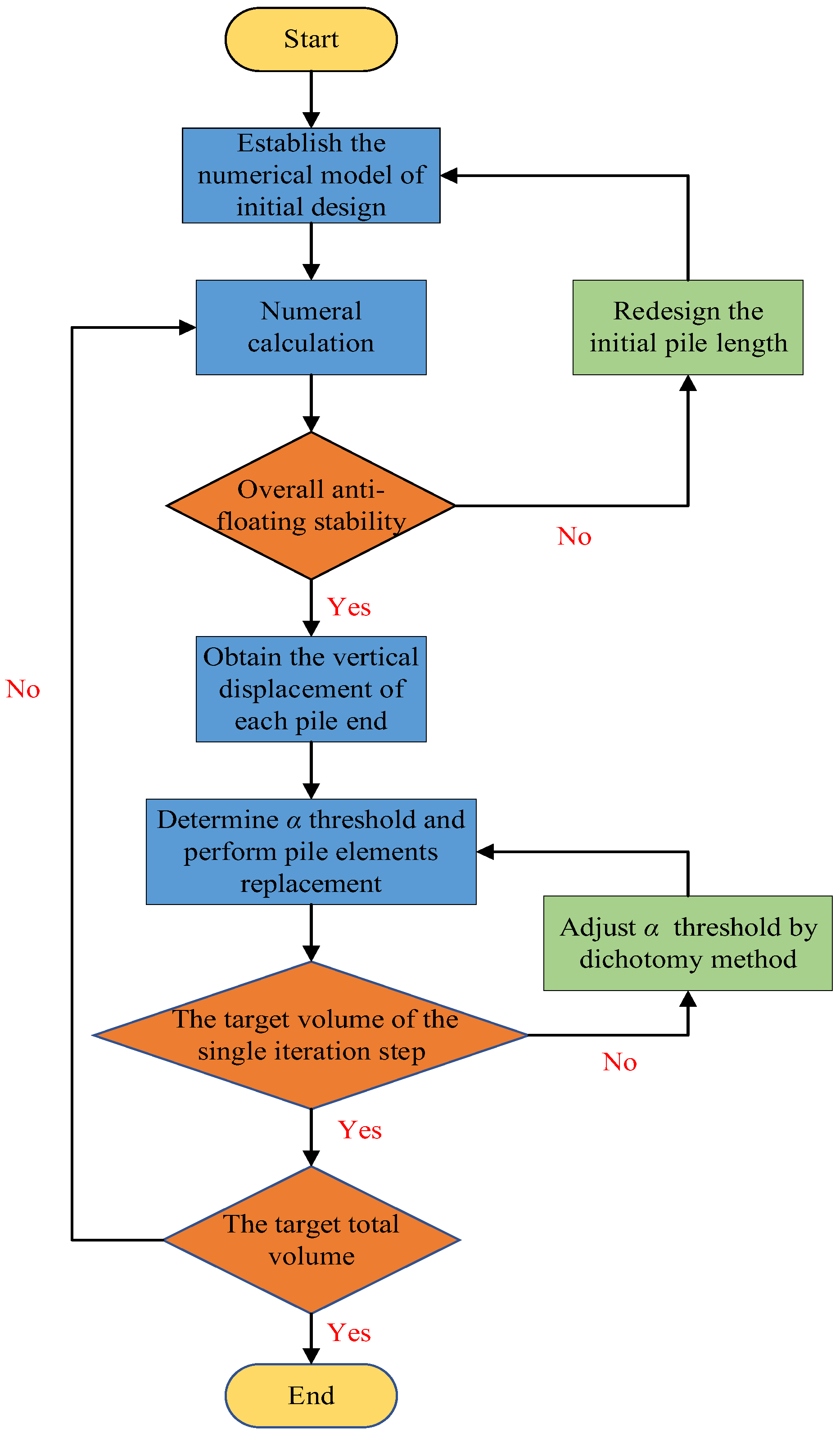
where uemax and uemin are the maximum and minimum values of the pile end displacement, respectively. Secondly, comparing uei with αth, the pile end elements with uei < αth are regarded as inefficient elements and replaced with soil elements; that is, the pile elements are replaced. The pile end elements with uei > αth are regarded as effective elements, and the soil elements below them are replaced with pile elements; that is, pile element are added. Thirdly, calculate the current pile elements volume Vk, and judge whether it meets the target volume requirement of the single iteration step, namely, comparing Vk with Vk. Before entering the next iteration step, the current pile elements volume Vk must be equal to the target volume of this iteration step (i.e., Vk = Vk), otherwise, αth will be updated based on the dichotomy method. For example, if Vk > Vk, then by substituting uemin = αth into Equation (8), a new αth can be obtained. This increases the threshold; thus, more pile elements are replaced by soil elements, and the total volume of pile elements is reduced. On the contrary, uemax = αth can be substituted into Equation (8) to reduce the threshold and increase the amounts of pile elements. The above three steps are the process of increasing the length of the piles with insufficient pulling force and reducing the length of the piles with excessive pulling force. It should be noted that before each iteration, it is necessary to verify whether the current design meets the requirements of the overall anti-floating stability of the structure. If the requirements are not met, the initial pile length should be redesigned. However, the verification can be directly implemented in numerical calculation. If the buoyancy is greater than the total anti-floating force, the numerical calculation will not converge, and the vertical displacement of the base plate will become increasingly larger. Figure 3 shows the flow chart of the BESO process.

3. Verification Analysis

In this section, the proposed process is conducted with numeral calculations to optimize the pile lengths, including two cases with different pile diameters and spacing. The BESO program is compiled with Python. FLAC3D is used for numerical calculation, because it has a connection with Python, which can realize secondary development. The total strain energy is directly obtained by the FISH function.

3.1. Numerical Models

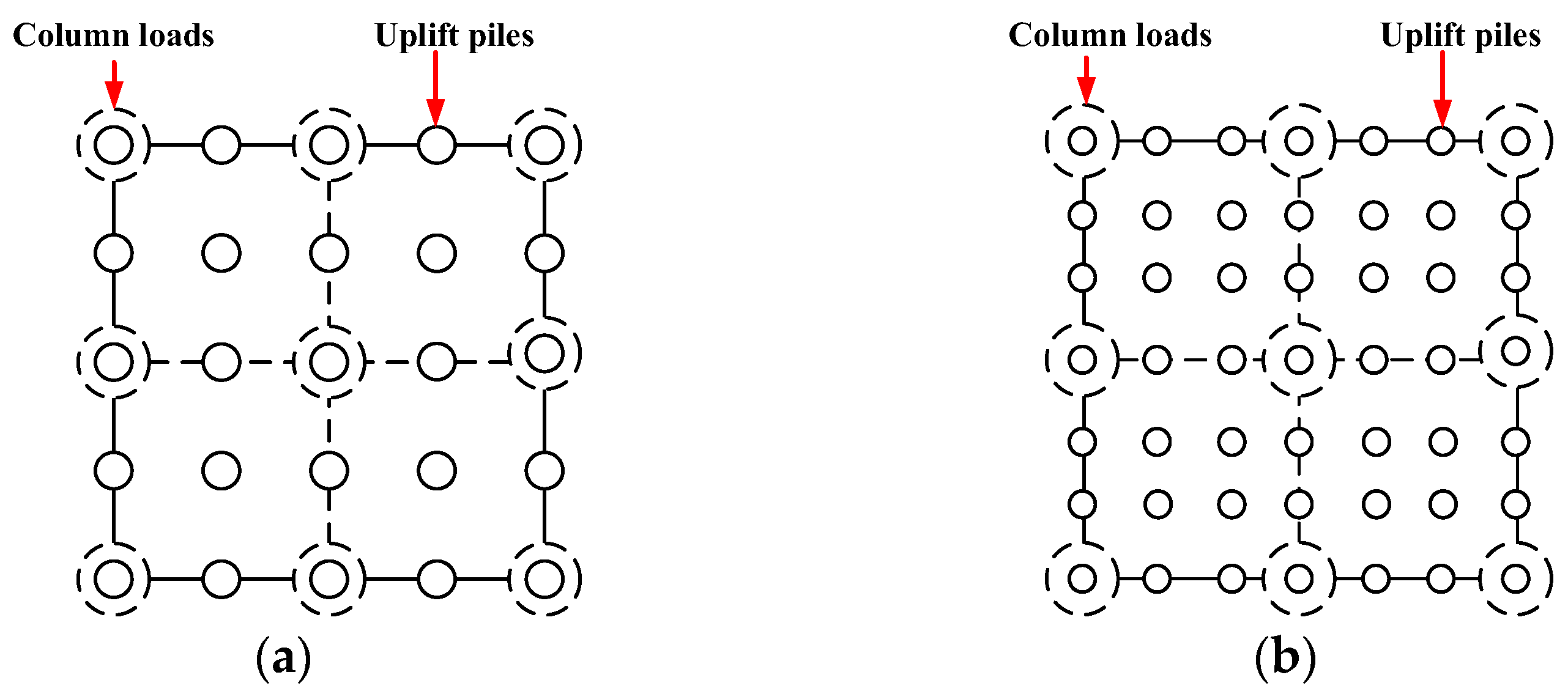
The frame structure with a base plate of 46 m × 30 m × 0.5 m is selected as an example. The drawback of the BESO process is that the optimization result will be affected by the initial design, and the local optimal solution may be obtained. The proposed process takes the pile length as the design variable. However, for the design parameters of the piles, in addition to the pile lengths, the pile diameters and the pile spacings should also be considered. Therefore, based on the same initial pile lengths and pile elements volume, two designs with different pile diameters and pile spacings are selected for optimization. The positions of piles and column loads in the two cases are shown in Figure 4.
For Case 1, the uplift piles are designed with large diameter and sparse distribution (LS). The pile spacing is 4.2 m, which is 1/2 column load net spacing. The pile diameter is 0.7 m. For Case 2, the uplift piles are designed with small diameter and dense distribution (SD). The pile spacing is 2.8 m, which is 1/3 column load net spacing. The pile diameter is 0.486 m. The initial pile length for both cases is 16 m. Two three-dimensional numerical models are established as shown in Figure 5. The concentrated force of 8400 kN is applied to the base plate instead of the single column load. The radial mesh system is used for both cases. Due to mesh size having a significant impact on the variation in the pile length in the proposed process, meshes are equally divided in the vertical direction, and the vertical size of each mesh is 0.5 m.
The Mohr–Coulomb constitutive model is used for the soil, and the linear elastic constitutive model is used for the base plate and piles. The interface element is used to simulate the slip between the pile and soil. The constitutive parameters of the soil, base plate, and uplift piles are presented in detail in Table 1. Parameters of the interface element are derived from the user manual in the FLAC3D help document. A uniform load of 120 kPa upwards is applied to the base plate instead of water pressure (i.e., hydraulic head = 12 m).

3.2. Variation of Total Strain Energy and Maximum Differential Deformation

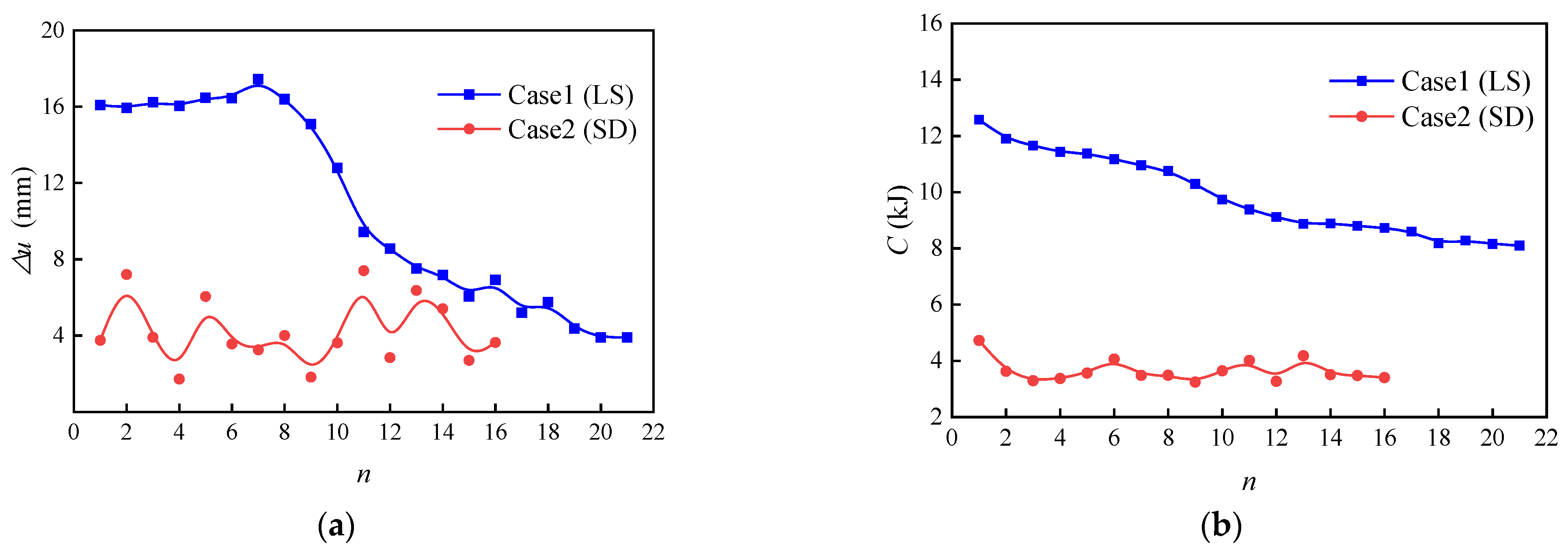
By conducting the BESO program and the numerical calculation, the pile lengths of Case 1 and Case 2 are optimized, respectively. Figure 6a,b are the varied history of the maximum differential deformation and the total strain energy of the base plate, respectively. When n is the number of iterations, Δu is the maximum differential deformation, and C is the total strain energy. Initially, the total volume of pile elements in both cases is V0. For Case 1, the residual volume of pile elements is 0.9 V0 after 12 iterations (i.e., 10% total volume of the pile elements is reduced). After 21 iterations, the residual volume is 0.8 V0 (i.e., 20% total volume of the pile elements is reduced). The total strain energy C of Case 1 gradually decreases and becomes stable as the iterations increase. Eventually, the iterative process converges. The maximum differential deformation Δu oscillates in the initial iterations, then decreases rapidly and eventually stable as the iterations increase. For Case 2, the residual volume of pile elements is 0.9 V0 after 7 iterations and 0.8 V0 after 16 iterations. However, for Case 2, the variation characteristics of C and Δu are different from those in Case 1. The value of C and Δu are small and oscillate as the iterations increase. It is indicated that although the BESO process reduces the total volume of the pile elements in Case 2, C and Δu do not decrease significantly with the iteration process and remain oscillating at a low level.
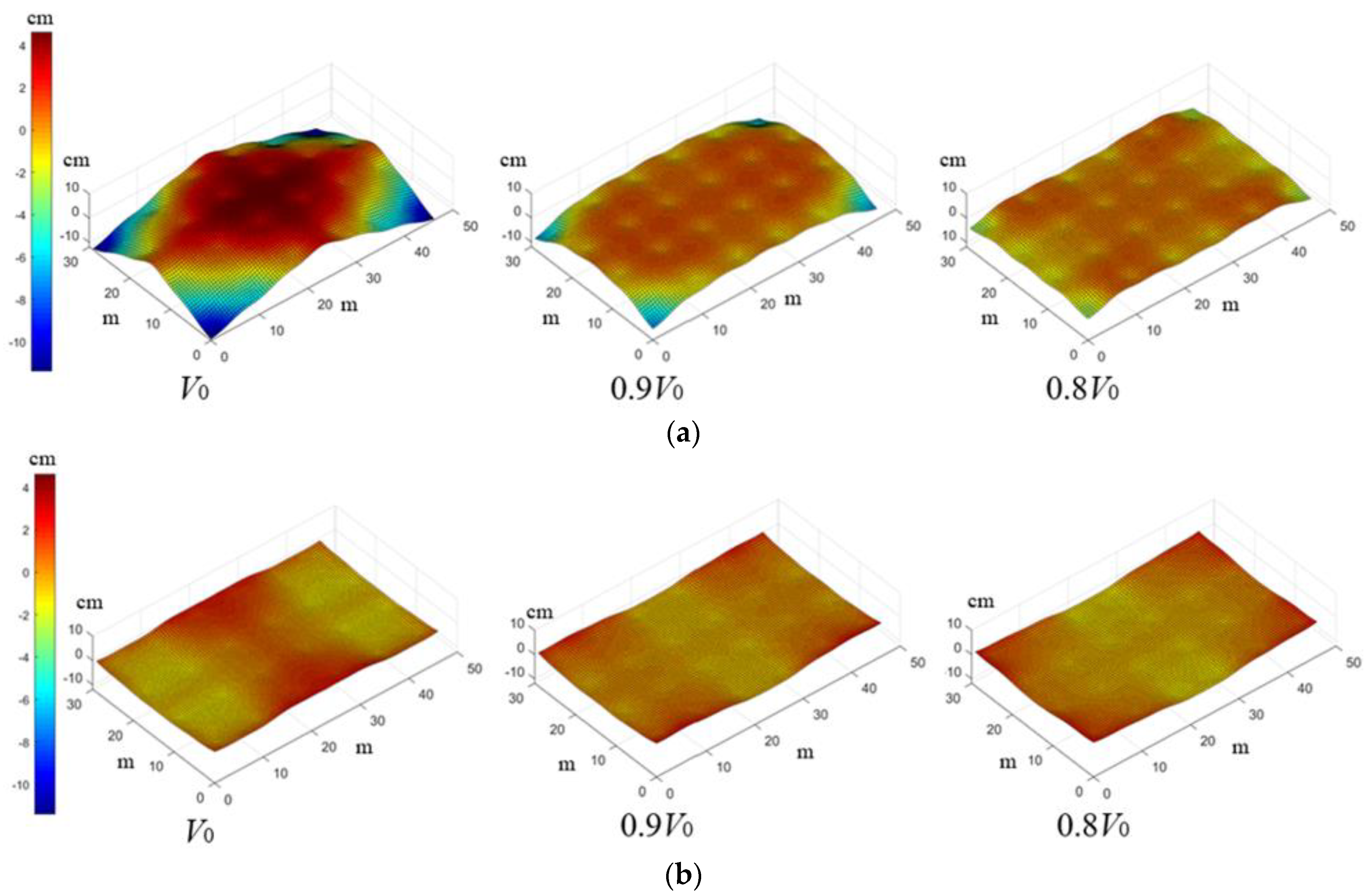
Figure 7 shows the vertical deformation contour of the base plate with different residual pile elements volumes in the two cases. Figure 7 has been standardized; the average deformation value of the base plate is used as the origin of the ordinate in each residual volume condition. For Case 1, when it is not optimized (i.e., residual volume is V0), the vertical deformation of the base plate is large in the middle and small in the periphery. As the iterations increase and the residual volume decreases, the maximum deformation in the middle gradually decreases, and minimum deformation in the periphery gradually increases, and the base plate gradually becomes flat. However, the positions of the maximum and minimum vertical deformation are basically fixed and do not change with the iterative process. Under the three residual volume conditions, the maximum differential deformation Δu is 16.09 mm, 8.56 mm, and 3.90 mm, respectively. The total strain energy C is 1.26 × 10⁴ J, 9.12 × 10³ J, and 8.08 × 10³ J, respectively. It indicates that the BESO process can significantly reduce the deformation degree of the base plate in that case by optimizing the distribution of pile lengths. However, for Case 2, the base plates are relatively flat under the three residual volume conditions; the positions of the maximum and minimum vertical deformation will change with the iteration process. It confirms that the deformation of the base plate maintains a relatively flat level and oscillates during the iteration process in that case.
In general, under the same residual volume conditions, the total strain energy C and maximum differential deformation Δu of the base plate in Case 2 are smaller than that in Case 1. From the comparison of the two cases in Figure 7, it can be seen intuitively that the base plate of Case 2 is much flatter than Case 1.

3.3. The Pile Length Distribution

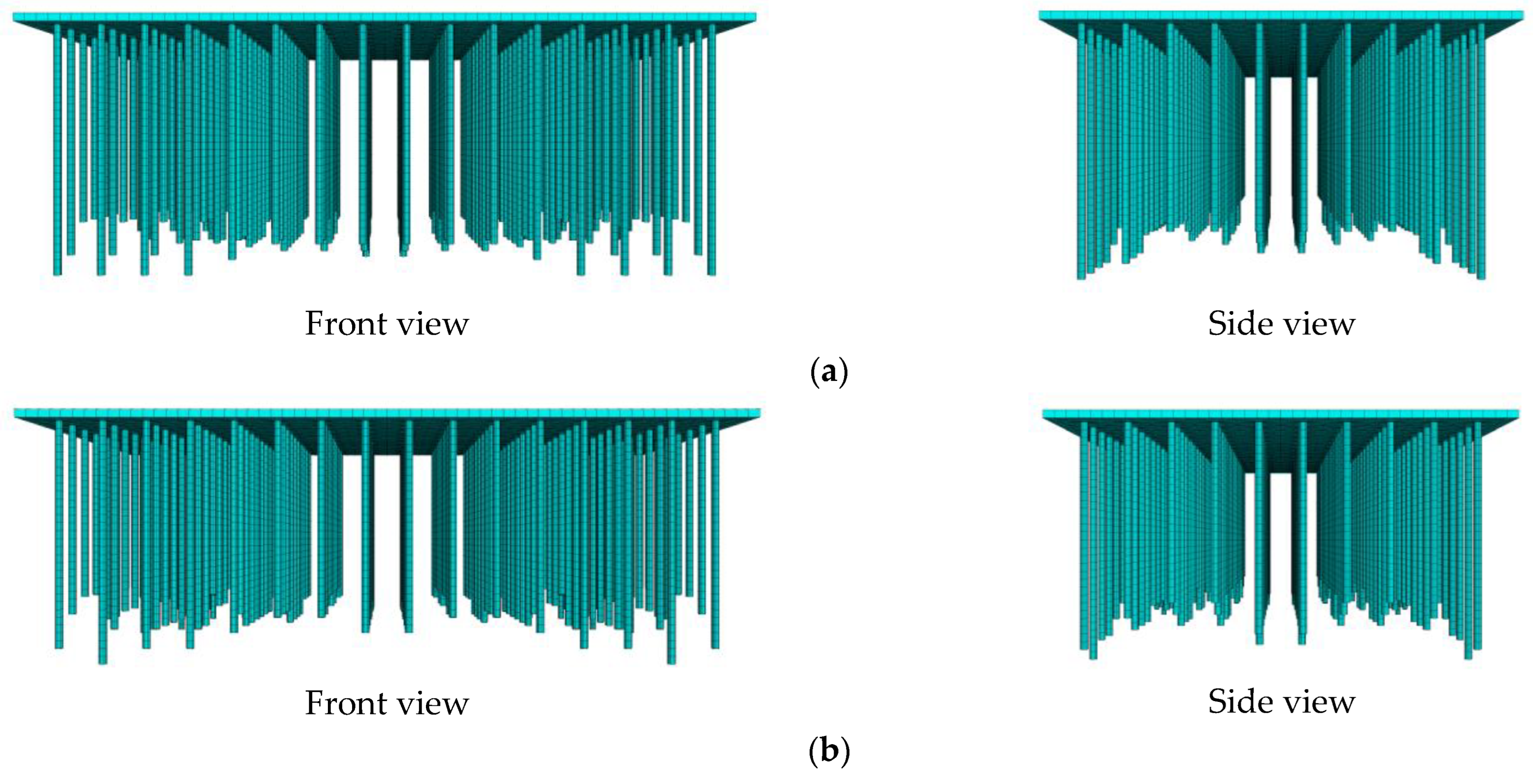
Figure 8a,b show the pile length distributions of Case 1 when the residual volume is 0.9 V0 and 0.8 V0, respectively. The distribution characteristics of the pile lengths under the two residual volume conditions are basically the same. The piles are longer in the center and gradually shorten from the center to the periphery. The column loads are beneficial to the anti-floating stability; thus, piles under the column loads are significantly smaller than the others. Figure 9a,b are the pile length distributions of Case 2 when the residual volume is 0.9 V0 and 0.8 V0, respectively. The lengths of each pile are basically the same. By comparing the distribution characteristics of pile lengths (Figure 8 and Figure 9) with the deformation characteristics of the base plate (Figure 7), it can be found that the distribution law of pile lengths is consistent with the deformation law of the base plate under the same residual volume conditions. It indicates that by optimizing the pile length, the distribution of the pile lengths and the deformation of the base plate can achieve the best consistency, so that the deformation degree of the base plate can be reduced.

3.4. Analysis

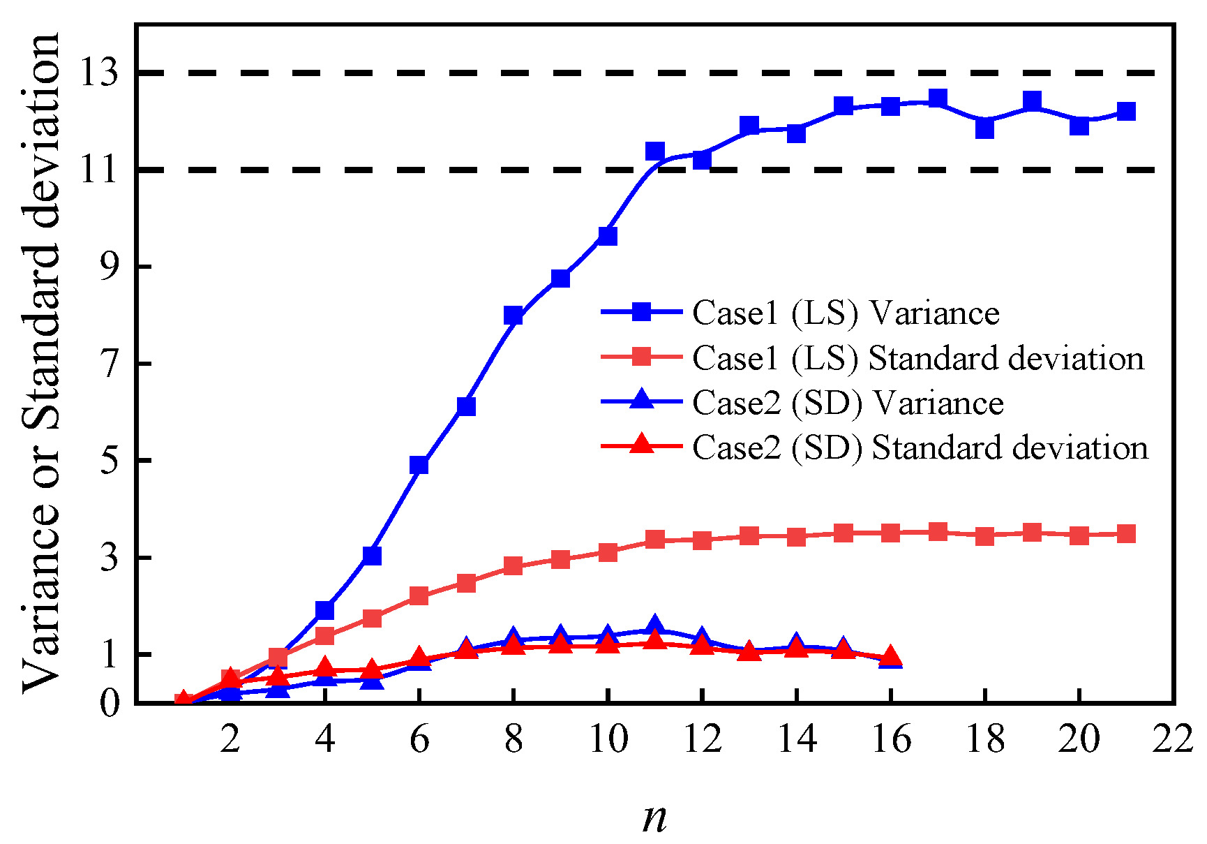
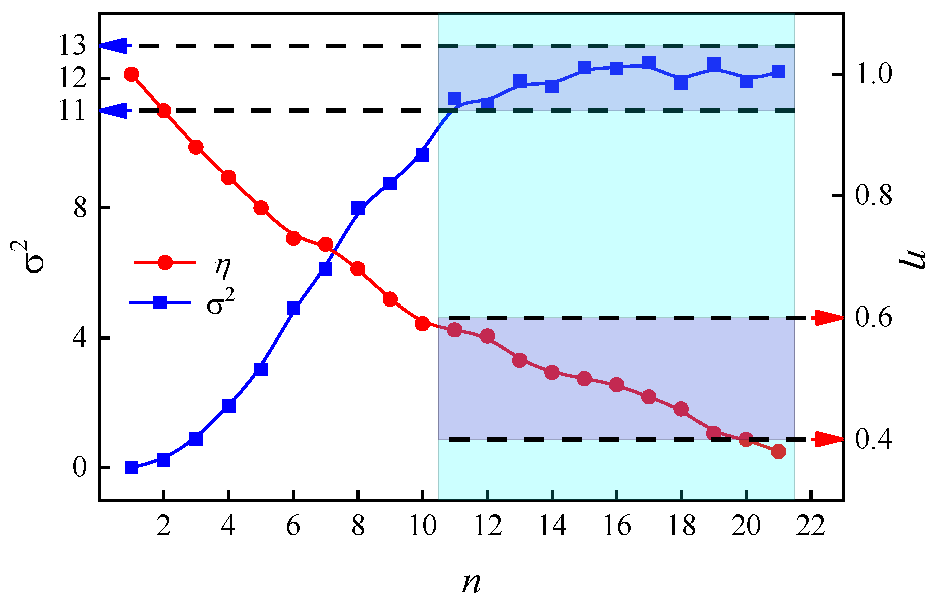
Figure 10 shows the history of the variance in and standard deviation of the pile lengths for the two cases. For Case 1, after 11 iterations, the variance in pile lengths no longer changes significantly and is close to the interval [6,16]. It indicates that with the increase in iterations and the decrease in C and Δu, the dispersion degree of the pile lengths remains constant. The ratio of the shortest pile length to the longest pile length in each iteration step of Case 1 is defined as η. Figure 11 shows the comparison of η and the variance. When the variance in pile lengths remains constant, η is in the range of 0.4~0.6; that is, the shortest pile length at the edge of the base plate is about 0.4 to 0.6 times the longest pile length in the center. However, for Case 2, the variance in and standard deviation of the pile lengths have no significant change with the increase in iterations, and they are much smaller than those in Case 1. The dispersion degree of the pile lengths is small, and each pile is close to the same length. Due to the oscillation variation characteristics of C and Δu in this case (shown in Figure 6), it implies that when the design of the uplift piles adopts small pile diameters and dense spacing, the optimization of the pile length has no significant effect on reducing the deformation degree of the base plate.
Based on the optimization results of the two cases, the following conclusion can be drawn: In order to reduce the risk of local anti-floating instability of the base plate, the design of dense pile spacing (i.e., pile spacing less than 1/2 column net spacing) and a small pile diameter should be preferred; that is, two or more small diameter uplift piles should be arranged between the column loads. However, if there are special situations that must be considered. For example, when the pile is also used as a pressure-bearing pile, a large-diameter pile body should be used to meet the bearing capacity requirements. Moreover, there are dense pipelines below the base plate, and sufficient spacing between the uplift piles is required. In these situations, only the sparse pile spacing (i.e., pile spacing is greater than or equal to 1/2 column net spacing) and large pile diameters can be used; that is, a single large diameter uplift pile is arranged between the column loads. Thus, it is necessary to lengthen the piles at the center of the base plate and shorten the piles at the edge and under the column loads. In addition, the dispersion degree of the pile lengths should be controlled; the pile length ratio of the short pile to the long pile is about 0.4~0.6.

4. Case Study

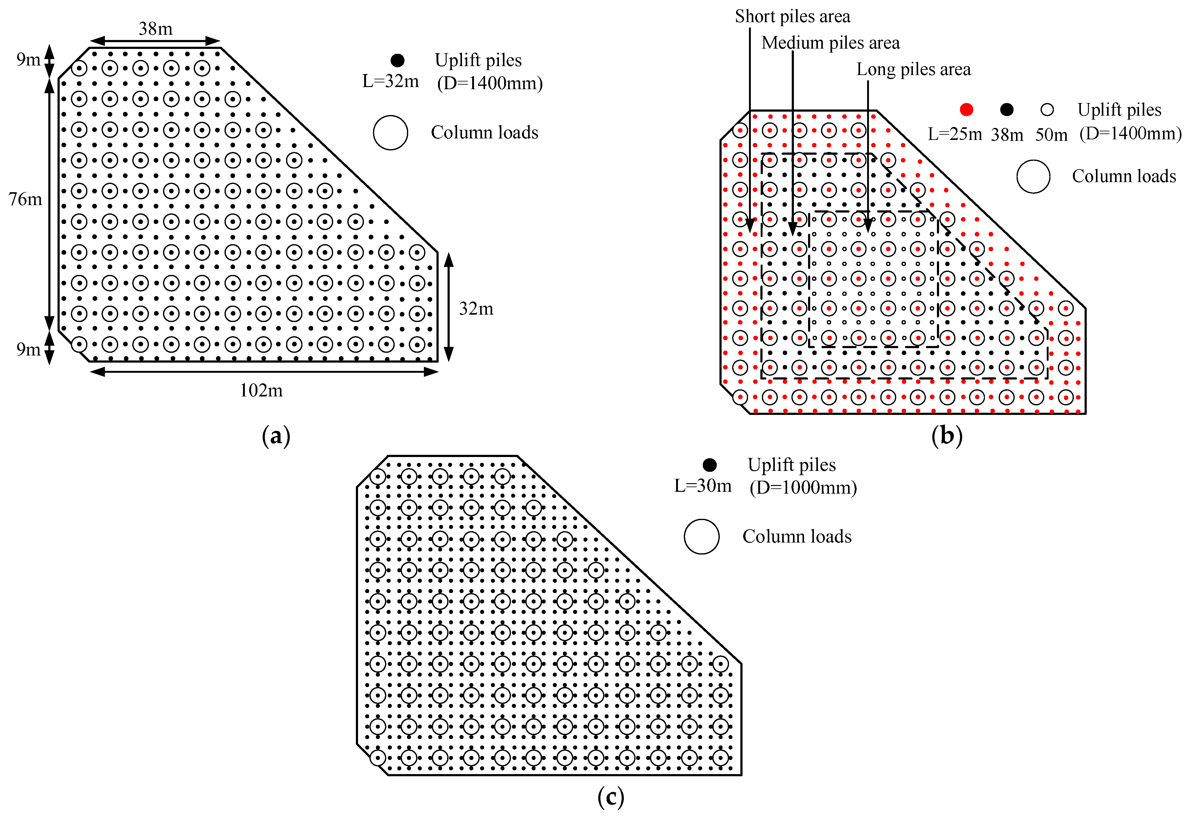
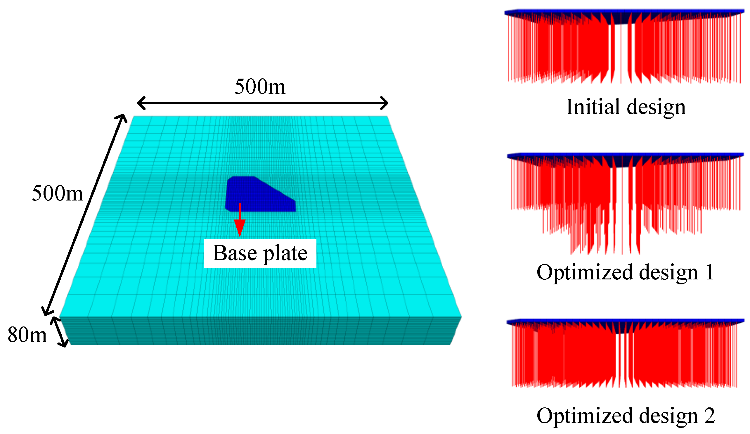
In this section, the design methods of uplift piles proposed in Section 3.4 are applied to practical projects. A foundation pit of the Beijing sub-center transportation hub was selected to investigate. Most of the structures in this project are underground stations and underground commercial areas near the North Canal, so the structures have high requirements for anti-floating stability. The bottom of this pit has no structures such as crossing tunnels or shield wells, and the base elevation is the same. The layout and design parameters of the uplift piles of the original design and the two optimized designs are shown in Figure 12 and Table 2:
In the original design, the piles are designed with the large diameter and sparse spacing. Based on the same total volume of piles, the same pile diameters and the same pile spacings, the pile lengths is dispersion in optimization design 1. Although the BESO process can significantly reduce the deformation of the base plate by optimizing the distribution of pile lengths, the pile lengths after optimization are extremely uneven, which is inconvenient for engineering construction. Therefore, only three different pile lengths are selected for optimization design 1. The piles in the center area of the base plate are the longest, the piles at the edge area and under the column loads are the shortest. The shortest pile length is half of the longest pile length. There is a transition area between the long pile area and the short pile area, and the pile lengths in that area are selected at 1.5 times the shortest pile length. For optimization design 2, the total volume of the piles remains unchanged; the piles are designed with a small diameter and dense spacing. The numerical models shown in Figure 13 are established based on the three designs, and the parameters of the models are shown in Table 3.
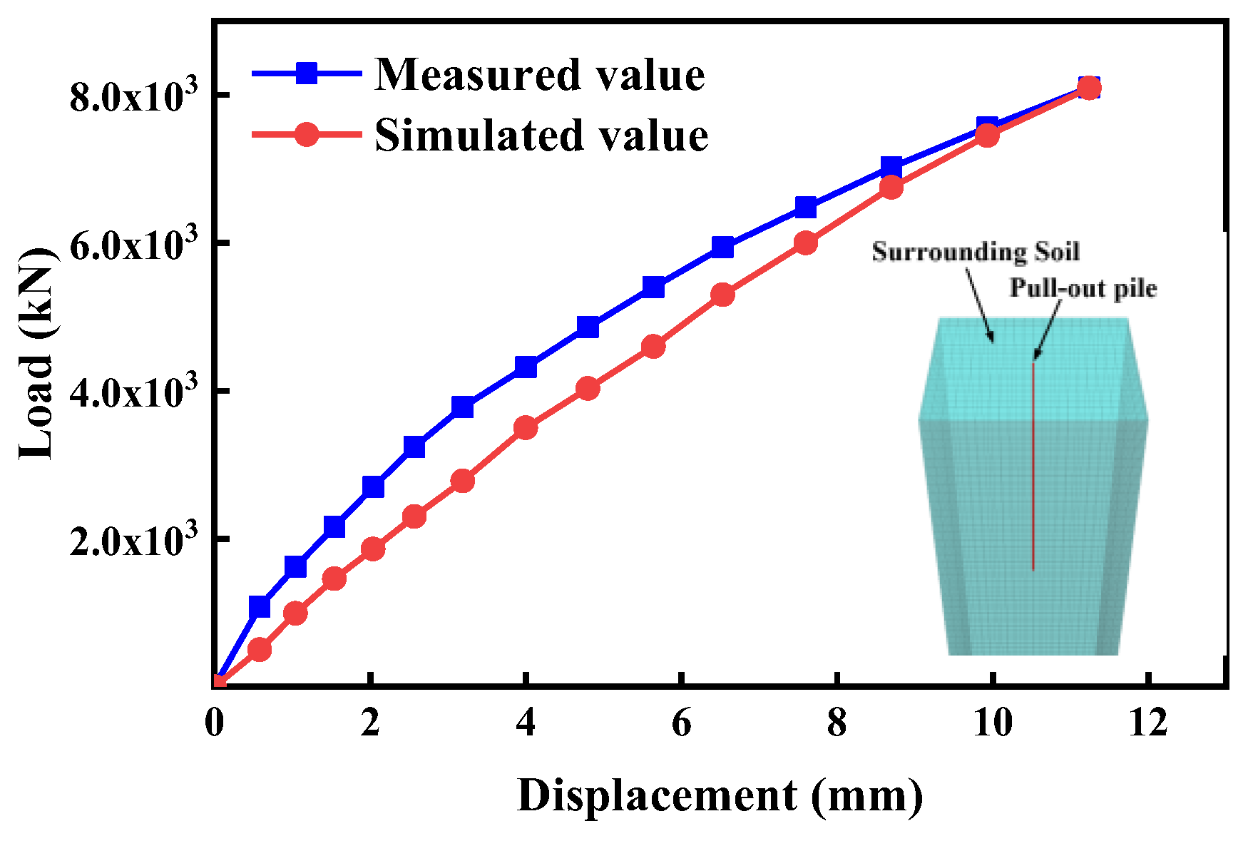
Due to a large number of piles in this model, the pile elements are used to replace solid elements of piles to improve calculation efficiency, and column loads are replaced by concentrated forces (8000 kN). The measured data of the single-pile pulling experiment are used to determine the parameters of the pile element. The diameter of the pile is 1000 mm, and the length of the pile is 30 m in the experiment. The corresponding numerical model is established; by adjusting the parameters of the pile element, the load–displacement curve of the pile crown is fitted with the measured data (Figure 14). The parameters of the pile element are shown in Table 4.
The numerical results of the maximum uplift, maximum differential deformation, and total strain energy for the base plate are shown in Table 5, and the vertical deformation contours are shown in Figure 15. Compared with the original design, the three indicators in optimization design 1 are reduced by 34.4%, 55.8%, and 19.24%, respectively, and those in optimization design 2 are reduced by 25.2%, 35.5%, and 26.0%, respectively. Optimization design 2 (small pile diameter and dense spacing) has the smallest total strain energy, which proves that the deformation degree of the base plate in this design is the smallest among the three designs. Compared with the original design, the maximum uplift is significantly reduced, the deformation is more uniform, and the differential deformation is smaller in the two optimization designs. It proves that the design method of uplift piles proposed in Section 3.4 has good engineering applicability.

5. Conclusions

In this paper, the optimization of uplift piles for the base plate is investigated considering local anti-floating stability. An optimization process is proposed based on the BESO method, with the pile length as the design variable and the pile end displacement as the sensitive coefficient. Consequently, a series of numerical simulations are conducted by using FLAC3D. The key findings are as follows.
  • When the uplift piles for the base plate adopts large pile diameter and sparse spacing, the initial deformation degree of the base plate is large. The BESO process can greatly reduce the maximum differential deformation and total strain energy of the base plate. After optimization, the dispersion degree of pile lengths distribution is large.
  • When the uplift piles for the base plate adopts small pile diameter and dense spacing, the initial deformation degree of the base plate is small. During the optimization process, the maximum differential deformation and total strain energy are small and oscillated. After optimization, the pile lengths are close.
  • To consider the local anti-floating stability of the base plate, the uplift piles should be preferably designed with small pile diameters, dense spacing, and equal pile lengths. If only the design of large pile diameter and sparse spacing can be adopted, long piles should be arranged at the center area of the base plate; short piles should be arranged at the edge area and under the column loads. The length ratio of the short piles to the long piles should be about 0.4~0.6.
  • The deformation degree of the base plate of optimization design 1 (large pile diameter and sparse spacing, unequal pile lengths) and optimization design 2 (small pile diameter and dense spacing, equal pile lengths) are significantly lower than the original design. It proves that the two optimization designs can effectively increase the local anti-floating stability for the base plate.
  • In the numerical calculation related to the pile resistance, if the model has a large area of the base plate and a large number of piles, in order to improve the computational efficiency, the solid unit of the pile has to be replaced by the built-in pile unit in the numerical software, and it is still necessary to study and develop the topology optimization methods and procedures applicable to the pile unit, so as to promote the application in the actual engineering.

Author Contributions

Methodology, M.Y.; writing—original draft, M.Y.; funding acquisition, M.Y. and P.L.; visualization, J.W.; writing—review & editing, J.W.; software, Q.L.; formal analysis, Q.L.; investigation, Q.L.; data curation, J.W.; supervision, P.L. All authors have read and agreed to the published version of the manuscript.

Funding

This research was funded by the Natural Science Foundation of China under Grant No. 51978018, Supported by Science and Technology Funding Scheme for the Third Construction Engineering Company LTD. of China Construction Second Engineering Bureau No. CSCEC2b3c-2021-K-65.

Institutional Review Board Statement

Not applicable.

Informed Consent Statement

Not applicable.

Data Availability Statement

The original contributions presented in the study are included in the article, further inquiries can be directed to the corresponding author.

Acknowledgments

The authors greatly appreciate the financial support from funding bodies and would be grateful to the reviewers for their valuable comments and suggestions to improve the quality of the paper.

Conflicts of Interest

Author Meng Yang was employed by the company The Third Construction Engineering Company LTD. of China Construction Second Engineering Bureau. The remaining authors declare that the research was conducted in the absence of any commercial or financial relationships that could be construed as a potential conflict of interest. The authors declare that they have no known competing financial interests or personal relationships that could have appeared to influence the work reported in this paper. Meng Yang is employee of The Third Construction Engineering Company LTD. of China Construction Second Engineering Bureau, who provided funding and teachnical support for the work. The funder had no role in the design of the study; in the collection, analysis, or interpretation of data, in the writing of the manuscript, or in the decision to publish the results.

References

  1. Wong, I. Methods of resisting hydrostatic uplift in substructures. Tunn. Undergr. Space Technol. 2001, 16, 77–86. [Google Scholar] [CrossRef]
  2. Foster, S.; Chilton, J.; Nijsten, G.-J.; Richts, A. Groundwater—A global focus on the ‘local resource’. Curr. Opin. Environ. Sustain. 2013, 5, 685–695. [Google Scholar] [CrossRef]
  3. Li, H.-Q.; Parriaux, A.; Thalmann, P.; Li, X.-Z. An integrated planning concept for the emerging underground urbanism: Deep City Method Part 1 concept, process and application. Tunn. Undergr. Space Technol. 2013, 38, 559–568. [Google Scholar] [CrossRef]
  4. Attard, G.; Winiarski, T.; Rossier, Y.; Eisenlohr, L. Review: Impact of underground structures on the flow of urban groundwater. Hydrogeol. J. 2015, 24, 5–19. [Google Scholar] [CrossRef]
  5. Kou, H.-l.; Guo, W.; Zhang, M.-Y. Pullout performance of GFRP anti-floating anchor in weathered soil. Tunn. Undergr. Space Technol. 2015, 49, 408–416. [Google Scholar] [CrossRef]
  6. Gattinoni, P.; Scesi, L. The groundwater rise in the urban area of Milan (Italy) and its interactions with underground structures and infrastructures. Tunn. Undergr. Space Technol. 2017, 62, 103–114. [Google Scholar] [CrossRef]
  7. Chheng, C.; Likitlersuang, S. Underground excavation behaviour in Bangkok using three-dimensional finite element method. Comput. Geotech. 2018, 95, 68–81. [Google Scholar] [CrossRef]
  8. Pujades, E.; Jurado, A. Groundwater-related aspects during the development of deep excavations below the water table: A short review. Undergr. Space 2021, 6, 35–45. [Google Scholar] [CrossRef]
  9. Sun, W.; Han, F.; Liu, H.; Zhang, W.; Zhang, Y.; Su, W.; Liu, S. Determination of minimum overburden depth for underwater shield tunnel in sands: Comparison between circular and rectangular tunnels. J. Rock Mech. Geotech. Eng. 2022, 15, 1671–1686. [Google Scholar] [CrossRef]
  10. Ni, P.; Mei, G.; Zhao, Y. Antiflotation design for water tank using pressure relief technique. Mar. Georesources Geotechnol. 2017, 36, 471–483. [Google Scholar] [CrossRef]
  11. Chattopadhyay, B.C.; Pise, P.J. Uplift capacity of piles in sand. J. Geotech. Eng. 1986, 112, 888–904. [Google Scholar] [CrossRef]
  12. Emirler, B.; Tolun, M.; Yildiz, A. Investigation on determining uplift capacity and failure mechanism of the pile groups in sand. Ocean. Eng. 2020, 218, 108145. [Google Scholar] [CrossRef]
  13. Liu, B.; Jiang, C.; Li, G.; Huang, X. Topology optimization of structures considering local material uncertainties in additive manufacturing. Comput. Methods Appl. Mech. Eng. 2020, 360, 112786. [Google Scholar] [CrossRef]
  14. Alawneh, A.S. Modelling load–displacement response of driven piles in cohesionless soils under tensile loading. Comput. Geotech. 2005, 32, 578–586. [Google Scholar] [CrossRef]
  15. Moayedi, H.; Mosallanezhad, M. Uplift resistance of belled and multi-belled piles in loose sand. Measurement 2017, 109, 346–353. [Google Scholar] [CrossRef]
  16. Kong, G.Q.; Zhou, L.D.; Gu, H.W.; Qin, H.Y. An Approach for Capacity Calculation of Shaped Pile Group Under Uplift Load. Soil Mech. Found. Eng. 2018, 55, 270–276. [Google Scholar] [CrossRef]
  17. Zhang, M.; Xu, P.; Cui, W.; Gao, Y. Bearing behavior and failure mechanism of squeezed branch piles. J. Rock Mech. Geotech. Eng. 2018, 10, 935–946. [Google Scholar] [CrossRef]
  18. Chen, Y.; Deng, A.; Lu, F.; Sun, H. Failure mechanism and bearing capacity of vertically loaded pile with partially-screwed shaft: Experiment and simulations. Comput. Geotech. 2020, 118, 103337. [Google Scholar] [CrossRef]
  19. Dos Santos, J.; Tsuha, C. Uplift performance of helical piles with cement injection in residual soils. Can. Geotech. J. 2020, 57, 1335–1355. [Google Scholar] [CrossRef]
  20. Yang, Y.S.; Qiu, L.C. MPM simulation of uplift resistance of enlarged base piles in sand. Soils Found. 2020, 60, 1322–1330. [Google Scholar] [CrossRef]
  21. Zhou, J.; Huang, X.; Zhang, J.; Wei, L.; Yuan, J. Experimental Investigation of the Uplift and Lateral Bearing Capacity of Root Piles. Soil Mech. Found. Eng. 2021, 57, 473–479. [Google Scholar] [CrossRef]
  22. Nguyen, T.; Ghabraie, K.; Tran-Cong, T. Applying bi-directional evolutionary structural optimisation method for tunnel reinforcement design considering nonlinear material behaviour. Comput. Geotech. 2014, 55, 57–66. [Google Scholar] [CrossRef]
  23. Ren, G.; Zuo, Z.H.; Xie, Y.M.; Smith, J.V. Underground excavation shape optimization considering material nonlinearities. Comput. Geotech. 2014, 58, 81–87. [Google Scholar] [CrossRef]
  24. Zhang, W.; Zhang, R.; Wu, C.; Goh, A.T.C.; Lacasse, S.; Liu, Z.; Liu, H. State-of-the-art review of soft computing applications in underground excavations. Geosci. Front. 2020, 11, 1095–1106. [Google Scholar] [CrossRef]
  25. Liu, T.; Ding, L.; Meng, F.; Li, X.; Zheng, Y. Stability analysis of anti-dip bedding rock slopes using a limit equilibrium model combined with bi-directional evolutionary structural optimization (BESO) method. Comput. Geotech. 2021, 134, 104116.1–104116.13. [Google Scholar] [CrossRef]
  26. Tang, C.Y. Research on Bridge Modelling Design and Optimisation; Changsha University of Technology: Changsha, China, 2015. [Google Scholar]
  27. Jing, H.Z. Research on the Analysis and Topology Optimisation Method of Deep Foundation Pit Row Pile Internal Support Support System; Liaoning University of Science and Technology: Anshan, China, 2018. [Google Scholar]
  28. Wang, X.D.; Zhu, J.; Liu, H.b.; Chen, Z.H. Automated implementation of conceptual design and topology optimisation of steel frames for residential steel structures. Build. Struct. 2020, 50 (Suppl. S2), 566–573. [Google Scholar]
  29. Zhang, B.Z.; Yin, B.; Chen, Y.J.; Liu, X.; Fang, Y.M. A review of research on design methods for reinforced concrete members based on topology optimisation. J. Wuhan Univ. Eng. Ed. 2022, 55, 462–473. [Google Scholar]
  30. Liu, J.L.; Zhu, N.H. Lightweight design of H-beam web section based on topology optimisation. J. Appl. Mech. 2021, 38, 2275–2283. [Google Scholar]
  31. Fang, T.H. Research on Topology Optimisation Method of Foundation Pit Internal Support Based on BESO Algorithm; Liaoning University of Science and Technology: Anshan, China, 2023. [Google Scholar]
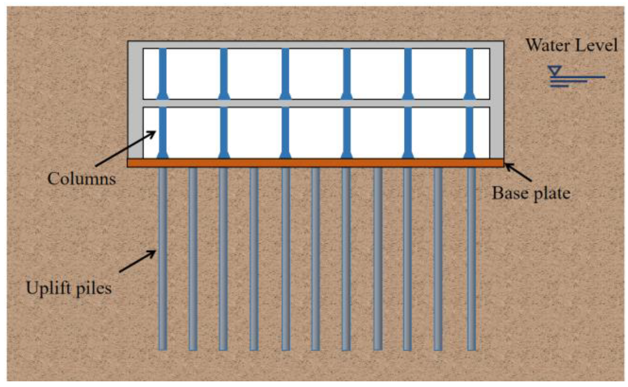
Figure 1. Uplift piles for an underground structure.
Applsci 14 05000 g001
Figure 2. Force analysis of a base plate.
Applsci 14 05000 g002
Figure 3. The flow chart of the BESO process.
Applsci 14 05000 g003
Figure 4. Initial designs of uplift piles: (a) Case 1: large, sparse (LS); (b) Case 2: small, dense (SD).
Applsci 14 05000 g004
Figure 5. Numerical model: (a) Case 1 (LS); (b) Case 2 (SD); (c) A’-A sectional view.
Applsci 14 05000 g005
Figure 6. The varied history: (a) maximum differential deformation; (b) total strain energy.
Applsci 14 05000 g006
Figure 7. The vertical deformation contour of the base plate: (a) Case 1 (LS); (b) Case 2 (SD).
Applsci 14 05000 g007
Figure 8. The pile length distribution of Case1 (LS): (a) residual volume is 0.9 V0; (b) residual volume is 0.8 V0.
Applsci 14 05000 g008
Figure 9. The pile length distribution of Case2 (SD): (a) residual volume is 0.9 V0; (b) residual volume is 0.8 V0.
Applsci 14 05000 g009
Figure 10. Variation in variance and standard deviation.
Applsci 14 05000 g010
Figure 11. Variance and η in Case 1.
Applsci 14 05000 g011
Figure 12. The layout of the uplift piles: (a) original design; (b) optimization design 1; (c) optimization design 2.
Applsci 14 05000 g012
Figure 13. Numerical models.
Applsci 14 05000 g013
Figure 14. The pile crown load–displacement curve.
Applsci 14 05000 g014
Figure 15. The vertical deformation contour.
Applsci 14 05000 g015
Table 1. Parameters of numerical model.
Material PropertiesPileBase PlateSoilInterface Element
Elastic modulus (GPa)25250.1/
Poisson’s ratio0.20.20.3/
Friction angle (°)//2020
Cohesion (kPa)//3030
Tangential stiffness (kN/m)///1 × 105
Normal stiffness (kN/m)///1 × 105
Table 2. Parameters of uplift piles.
DesignPile Spacing
(m)
Plie Diameter
(mm)
Pile Length
(m)
Column Spacing
(m)
Original design4.51400329
Optimization design 14.5140050, 38, 259
Optimization design 231000309
Table 3. Parameters of numerical model.
Model PropertiesValue
Length × Width × Height (m)500 × 500 × 80
Young’s modulus of soil (GPa)0.13
Poisson’s ratio of soil0.3
Friction angle of the soil (°)20
Cohesion of soil (kPa)30
Hydraulic head (m)20
Thickness of the base plate (m)1.5
Bulk modulus of the base plate (GPa)13.9
Shear modulus of the base plate (GPa)10.4
Table 4. The parameters of the pile element.
Pile Element PropertiesValue
Young’s modulus (GPa)60
Poisson’s ratio0.3
Tangential stiffness (KN/m)2 × 108
Normal stiffness (KN/m)2 × 108
Tangential friction angle (°)28
Tangential cohesion (KPa)30
Normal friction angle (°)0
Normal cohesion (KPa)0
Table 5. Numerical calculation results.
DesignMaximum Uplift
(mm)
Maximum Differential Deformation (mm)Total Strain Energy
(J)
Original design25.3417.7145,864
Optimization design 116.637.8337,039
Optimization design 218.9511.4233,955
Disclaimer/Publisher’s Note: The statements, opinions and data contained in all publications are solely those of the individual author(s) and contributor(s) and not of MDPI and/or the editor(s). MDPI and/or the editor(s) disclaim responsibility for any injury to people or property resulting from any ideas, methods, instructions or products referred to in the content.