Abstract
Earthquakes and floods in Albania are devastating, but combining these two different hazards in terms of action on bridge structures may lead the bridge to collapse. This article presents a seismic risk assessment of a code-conforming precast reinforced concrete bridge located in a region prone to earthquakes and where local scour induced by floods is a significant concern. The seismic action is considered using a group of ground motion accelerograms generated by matching the accelerogram of the 29 November 2019 earthquake in Durres (M = 6.4), Albania, to the target response spectrum. The scouring effects on the bents of the bridge are characterized by the scour depths. A set of non-linear time-history analyses of the bridge are performed to assess the bridge’s performance. The bridge fragility curves are generated and analyzed for multi-hazard scenarios at both element and system levels for different flow discharge values and PGA levels. The result shows a low seismic risk of the bridge with bearings when considering the local scour induced by flood events in the seismic analysis due to their flexibility to adapt to changes in structure geometry and significant foundation stiffness. This research also emphasizes the significance of choosing the right foundation type and depth for bridges located in areas prone to local scour induced by floods.
1. Introduction
Every nation relies on its infrastructure as a cornerstone, with bridges playing vital roles in highway and railway transportation networks. Bridges are critical in supporting first responders during the aftermath of destructive earthquakes and facilitating post-disaster rescue operations, particularly in remote areas. Bridges are susceptible to various natural hazards, including earthquakes, high winds, landslides, floods, and other hazards like explosions and vehicle collisions at bridge bents and abutments. Studying the causes that have led to damage up to the collapse of bridges throughout history, mainly under strong seismic actions and flood-induced scours, has significantly improved design codes and structural health monitoring techniques.
Combining two different natural hazards of earthquakes and floods in terms of action on bridge structures may lead a bridge to collapse. Albania is identified as a region with significant seismic activity resulting from the interaction of the Adriatic and Aegean Seas’ multiple tectonic plates and complex tectonic processes in the Carpathian region [1]. The damage potential of active seismic faults has been evident in numerous earthquakes, such as the 30 November 1967 earthquake measuring M = 6.6 in Dibra and Librazhd, the 15 April 1979 earthquake measuring M = 6.9 in Montenegro, and the earthquakes on 21 September and 26 November 2019, registering magnitudes of M = 5.8 and M = 6.4, respectively, in Durres, Albania. Floods in Albania happen more frequently, and the sum of the impact of every single one of them may cause a substantial loss. Bridge flood-induced scour is a significant concern in areas prone to earthquakes and can be compounded by climate change. Hydraulic events are the primary cause of bridge failures globally, with flood-induced scour representing a significant factor in hydraulic-related failures [2]. Scouring results from the erosive force exerted by flowing water, which removes and transports sediment from the streambed and banks and the surrounding areas near the bents and abutments of the bridge [3]. As a result, the restraining conditions of bents at the foundation may be modified. Consequently, the lateral capacity of bents might decrease. This additional flexibility leads to varying dynamic characteristics of the structure, which can exacerbate the detrimental impact of seismic ground motions on structure performance [4].
Avşar (2009) [5] meticulously formulated a fragility analysis for road bridges in Turkey built and constructed post-1990s, a crucial step in understanding their vulnerability. These fragility curves address three levels of damage states (DS), primarily influenced by the relative movement of the deck. In 2015, Yilmaz [6] conducted a comprehensive investigation on two actual river-crossing highway bridges and two representative examples, providing invaluable insights into regional multi-hazard scenarios, including earthquakes and floods, across diverse regions in California. These bridges were built at varying points in time, making the study’s findings even more significant. The study involved the generation of fragility curves and surfaces in predicting the probability of bridge failures under different levels of earthquakes and floods, a crucial tool for risk assessment.
European design codes currently lack guidelines to guarantee adequate bridge foundations that are resistant to scouring and subjected to earthquake lateral loading. This gap in our knowledge and practices is a call to action for all of us, as Eurocodes do not cover the scour and flood effects approach in bridge foundation design. The Italian Code for Construction (NTC 2018, 17 January 2018, 5.1.2.3) for new bridges suggests avoiding, where possible, bents placed in the riverbed. If necessary, the distance between consecutive bents or between a bent and bridge abutment must be at least 40 m measured perpendicular to the mainstream [7]. Much research revolves around analyzing the risk and reliability of bridges during specific extreme occurrences like earthquakes, storm surges, winds, floods, and collisions, typically relying on proprietary computational models. Recent findings underscore the reality that bridges are exposed to extreme events over their operational duration. Albania faces multiple sources of hazards. Hence, it is imperative to reevaluate the design criteria that have traditionally been formulated using a single-hazard approach. Clarke and Obrin (2016) [8] implemented a stress testing approach focused on assessing the combined risk posed to critical infrastructure networks by various severe hazard events, including earthquakes, landslides, and floods, and to assess how effectively the entire network can endure highly unlikely yet severe natural hazard events. This framework offers a valuable tool for transport infrastructure owners and managers to address the challenges posed by extreme natural hazards and enhance the resilience of transportation networks. Crespi et al. (2020) [9] and Crespi et al. (2022) [10] emphasized the importance of evaluating the impact of the corrosion effects caused by the carbonation phenomenon (for three different levels) on the seismic performance of existing concrete and precast bridges. The corrosion effects are applied by reducing the cross-section of steel rebars. The proposed procedure identifies the first structural component reaching failure providing valuable insights into retrofitting strategies.
Compared with current research on continuous concrete bridges, the study work carried out by Wang et al. (2014) [11] shows that the multi-span, simply supported bridge is more sensitive to flood hazards than a continuous concrete bridge. Also, both bridges benefit from scouring due to longer modal periods. This paper suggests enhancing the stiffness of foundations to mitigate the seismic risk of bridges with a scoured foundation, which leads to the same conclusion as the results achieved by this study.
The aim of this work is to assess the bridge’s performance using a probabilistic-based approach under multi-hazard scenarios involving seismic action and local scour induced by floods to the bridge by utilizing fragility functions. This study examines how the bridge responds when facing the sequential and combined effect of local scour and an earthquake, assessing its performance under these circumstances. Moreover, the study area is situated in a region with a notably elevated annual likelihood of experiencing floods. Fragility analyses are developed, and the probabilities of bridge failure considering different earthquake levels and local scour depths are calculated. These tools are valuable for determining the likelihood of bridge failure across various potential damage scenarios, correlating ground motion intensity with local scour depths [12,13,14]. This article emphasizes the importance of making bridges more resilient by adapting their structural capacities to the combined effect of natural hazards compounded by climate change.
2. Methodology
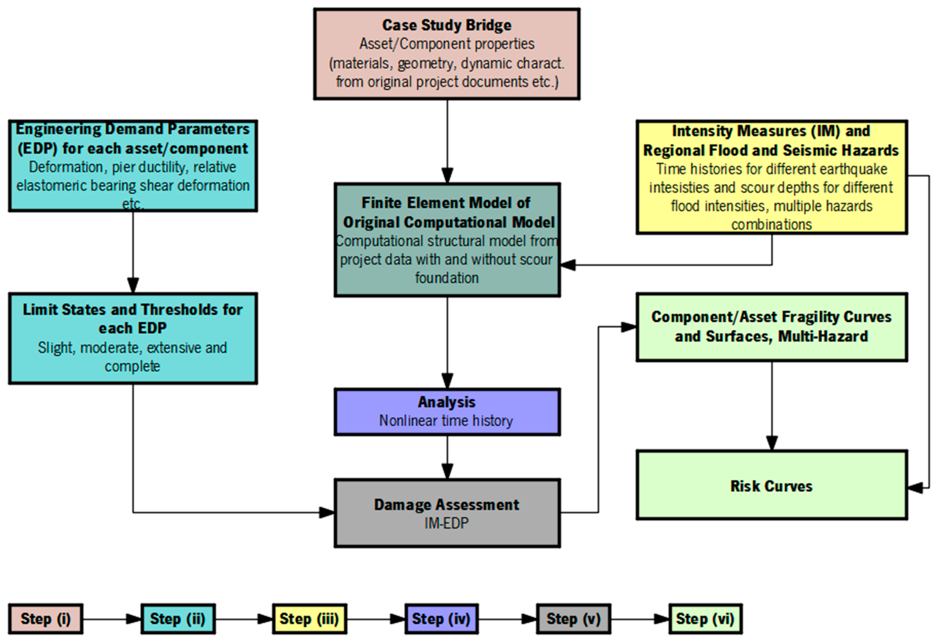
A comprehensive multi-hazard framework is developed to evaluate the reliability of a bridge situated in a region in Albania prone to seismic activity and flooding. This framework aims to measure the risk confronting the bridge when affected by both earthquake activity and local scour simultaneously. At the outset, a case study is initiated, and information is compiled from existing research sources. Subsequently, an FE model is built using the collected information. In parallel, earthquake accelerograms are generated and scour depths are calculated. Four damage limit states (DLS) are delineated, and fragility curves for its components and the system are developed. The outcomes are depicted through curves and surfaces of fragility function and risk evaluation, illustrating different multi-hazard scenarios.
The methodology outlined below consists of six steps and is visually depicted in a flowchart (Figure 1).

Figure 1.
Framework for assessment of bridge under earthquake and flood hazards.
2.1. Case Study Bridge and Numerical Model
As a case study, a road bridge is considered for the bridge assessment under seismic action and local scour. The bridge is situated in Urake, Diber and spans the Kurvajt River. All the information is gathered from the original project and other studies, and an FEM is built on CSIBridge v25.0.0. software considering time history accelerograms and scour depths for different probabilities of exceedance.
2.2. Engineering Demand Parameters
Defining damage limit states and aligning them with meaningful parameters for evaluating bridge conditions is vital to ensure the reliability of analytical fragility curves. These definitions, specific to various bridge components, are determined through the input of experts, empirical data, or analytical models. The meticulous definition of damage limit states plays a pivotal role in shaping the resulting fragility curves, making it a critical element in the overall process of developing analytical fragility curves and surfaces. No particular method establishes a direct correlation between the damage to the bridge and the different damage states. Threshold limits for different component damage states have been derived from earlier studies and are succinctly outlined in Table 1 for three Engineering Demand Parameters (EDP).

Table 1.
Damage threshold limits.
There is no indication of shear failure in any bents under the specific ground motions. The evaluation of bridge bents is based on their capacity to withstand bending, with curvature ductility μϕ, to assess flexural damage. The threshold values for curvature ductility are sourced from Ramanthan’s research (2012) [15] for post-1990 ductile columns. For abutment damage, the longitudinal deformation is considered (Δa,long). Threshold limits are taken from Stefanidou (2016) [16]. The condition of elastomeric bearings is assessed according to their horizontal longitudinal deformation. For moderate damage and complete failure, the threshold limits are established based on longitudinal deformation. In particular, a moderate damage state is characterized by the initiation of sliding at the interface between concrete and elastomer. At the same time, complete failure occurs when the bridge superstructure becomes detached from the pads. The threshold limit for extensive DS is computed by arithmetic mean between the thresholds associated with moderate damage and complete state [6].
When any bridge element reaches or exceeds a DLS, the entire bridge system is categorized into the same DS, regardless of the conditions of other bridge elements.
2.3. Intensity Measures (IM) and Flood and Earthquake Hazards
The expected strong and ground motion characteristics are delineated to generate fragility curves derived from real accelerograms and spectrum-matching techniques. A group of real earthquake accelerograms matched to the target response spectrum employing the wavelets algorithm introduced by Al Atik and Abrahamson [17] are generated and reflect seismic properties specific to the area of the bridge ensuring alignment with the soil conditions prevalent in the locality. Spectral matching adjusts the selected time history record to align with the target response spectrum. The spectrum functions as a reference point as the produced accelerograms will undergo refinement to align with its response spectrum. Eurocode 8 target response spectrum will be defined to produce the necessary adjusted records for each seismic level (agR = 0.05 g, 0.10 g, 0.20 g, and up to 0.5 g).
The impact of scouring on the bridge will be assessed based on the depths of the scour. Various equations have been proposed to forecast local scour depth under different riverbed conditions. Drawing from model-scale experiments, two commonly utilized equations are tailored for sand and clay bed streams. Since sand is the most susceptible to erosion, this study will concentrate on a bridge in a sand-bed stream.
This study addresses scour, which arises from the erosive impact of the river, by assessing the maximum depth of local scour induced by floods at the bent and abutment foundations. Scour can manifest in three forms: long-term riverbed degradation, local scour at bents and abutments foundations, and contraction scour at the bridge [3]. This study primarily examines the scouring of bents and abutment foundations caused by flowing water. The scour depths (ys) at bents and abutments are determined with the expression of HEC-18 [3]:
Correction factor K1 accounts for the nose shape of the bents, K2 accounts for the angle of the flow direction, and K3 accounts for the riverbed condition, y1 is the flow depth, a is the width of the bent, and Fr1 is the number of Froude. The equation provided is suitable for assessing local bent scour for a live bed and clear water. However, for this particular case study, the focus is on evaluating live-bed bent scour. Bridge scour depths calculated from Expression (1) will be incorporated into finite element analyses.
2.4. Analysis of Numerical Model
A 3D FEM was developed on CSIBridge v25.0.0 software using data related to bridge dimensions and materials gathered from the original project.
2.5. Damage Assessment
The damage assessment for the selected bridge components is conducted for each earthquake and scour scenario.
2.6. Fragility Curves and Surfaces Development
In the case of the studied bridge, each point along the fragility curve indicates the probability of achieving/surpassing a specific damage threshold due to seismic action at various scour depths. IM represents this motion on the fragility curve.
2.6.1. Fragility Curves at the Component Level
A two-parameter log-normal distribution (log-ND) characterizes the seismic fragility curve and is defined as follows [18]:
The function of fragility function F(xj;θk,βk) gives the probability of a seismic action with IM (PGA) = xj will lead to bridge element failure at DS k (slight, moderate, major, and complete). The function Φ( ) represents the cumulative distribution (CDF) with fragility parameters, θk (median) and βk (standard deviation), of the log-ND at damage state k, respectively. Given the logical presumption that xj for each seismic level operates independently, the fragility parameters are evaluated with the maximum likelihood method for truncated incremental dynamic analysis (IDA) [12]:
For n seismic levels used, there will be m seismic levels that cause failure at xj levels less than xmax, and n−m seismic levels that result in failure prior to the termination of the analyses.
2.6.2. System-Level Fragility Curves
The overall damage condition of the bridge, under a particular seismic level and scour depth induced by flood events, is established by pinpointing the most severe damage across all critical bridge elements. The parameters that characterize the fragility curve at the system level are computed utilizing the maximum likelihood approach.
2.6.3. Fragility Surfaces
Fragility surfaces illustrate the cumulative impact of seismic action in the presence of local scour on the likelihood of bridge failure across different damage states. Statistical independence is assumed among random variables of the intensity measures, which depict flood and earthquake hazards. The joint CDF of seismic action and local scour induced by flood yields the structural failure probability in a combined-effect scenario. Fragility surfaces are derived using the maximum likelihood method of bivariate log-normal distribution.
In this expression, the random variables of x1,j and x2,j denote peak ground acceleration and the annual peak flow discharge, respectively. The values of medians θ1,k and θ2,k and log-standard deviations β1,k and β2,k are given for damage state k. The bivariate log-normal distribution’s probability density function is derived using the Jacobian of the transformation and can be articulated as follows:
2.7. Risk Evaluation
The expected risk associated with earthquake and flood hazards concerning the bridge is delineated through risk curves. These curves present the annual probabilities of exceedance across different types of bridge rehabilitation expenses within the multiple impacts of seismic action and local scour induced by flood context. In the multi-hazard scenario denoted as m, the bridge rehabilitation cost for repair or replacement, designated as CRPm, is explicitly defined as follows [19]:
The probability pm(DS=k|am, dm) signifies the likelihood for which the examined structure can endure DS k given seismic level am (PGA), derived from the bridge’s fragility data, occurring alongside local scour dm. Cn denotes the replacement cost of the bridge. The values of damage ratios, rk, associated with damage k, as outlined in Table 2 and recommended in HAZUS (2022) [20], are employed.
Table 2.
Different damage ratios of bridge element.
In this research, the cost of repairing the bridge is determined in relation to its replacement value, with the damage ratio serving as the proportionality factor.
3. Case Study
Most Albanian bridges have short spans consisting of simply supported single-span or multiple-span with reinforced concrete or precast pre-stressed girders. This bridge class is of interest to assess the vulnerability and estimate the performance. Most of them are supported by pile foundations, offering protection against additional seismic action stemming from local scour induced by floods. Nevertheless, local scour can amplify the fragility of bridges, particularly at slight and moderate DS, as scouring adversely affects elements of the bridge superstructure. These insights will streamline bridge design considerations within the specified effect of combining earthquake and flood hazards.
3.1. Study Bridge
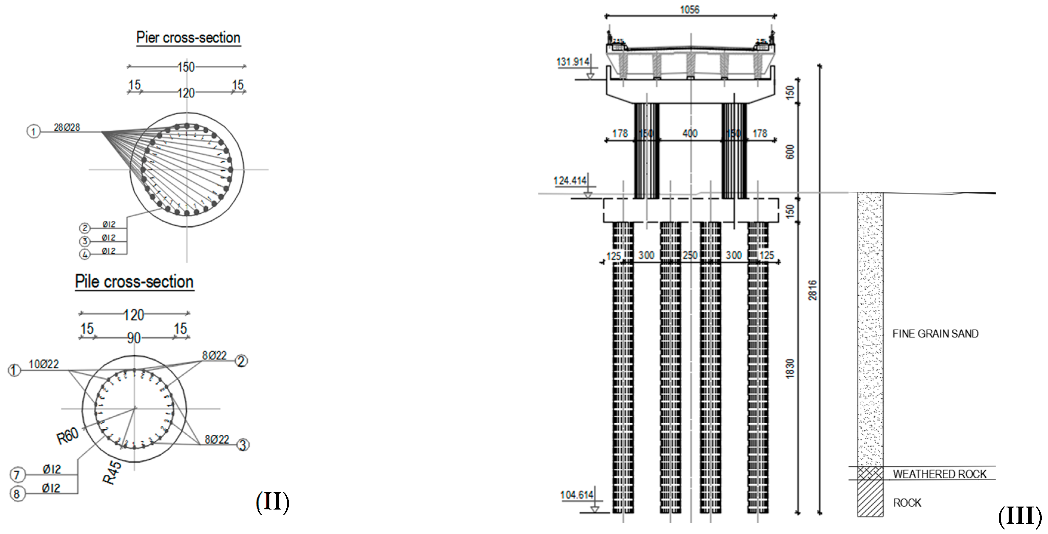
The bridge is on the segment of the “Urake—Ura e Shoshajve” road, crosses the Kurvajt River, and has six simply supported spans. The bridge was built in 2013, and drawings and details are given in Figure 2. The length of the bridge is 178.65 m. The foundation of the bridge is on a fine sandy layer. The bridge’s superstructure is constructed from precast post-stressed concrete I-girders and reinforced concrete slab connected monolithically with girders. The bridge’s superstructure relies on elastomeric bearings to support its I-girders. Each bridge bent consists of two reinforced concrete columns, each with a diameter of 1.50 m, interconnected with a monolithic bent cap. All bents exhibit identical cross-sectional dimensions and material characteristics. Each group of bents is supported by a set of reinforced concrete piles, each with a diameter of 1.2 m, capped with reinforced concrete pile caps. Expansion joints are installed at abutments and bents numbers 2 and 4 of the bridge. These joints create a separation of 50 mm within the bridge structure.
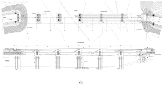

Figure 2.
Bridge details: (I) plan and longitudinal view; (II) cross-section of bents and piles; (III) cross-section of bridge at bent.
3.2. Flood and Earthquake Hazards
3.2.1. Earthquake Hazard
In conducting this study, the earthquake hazard is evaluated by referring to the seismic hazard map of Albania (PGA, 10% probability of exceedance in 50 years, and VS30 site condition of 800 m/s) [21], which provides information about peak ground acceleration for a 475-year RP and ground motion of the 26 November 2019 earthquake in Durres, Albania. The time history analysis focuses on the horizontal orthogonal directions of the earthquake. The bents are not subjected to high bending moments due to vertical permanent loads of superstructure, and so the vertical component of seismic action is not considered [22]. The time history acceleration chosen from a location near the bridge site is adjusted to align with the response spectrum outlined in Eurocode 8-1 [23], and the matched records for each seismic level (agR = 0.05 g, 0.10 g, 0.20 g, and up to 0.5 g) are generated. The defined target spectrum is Type 1 of the horizontal elastic response spectrum with a damping ratio of 5% and C-ground type. The importance factor for the bridge is equal to γI = 1.0 (importance class II, average importance).
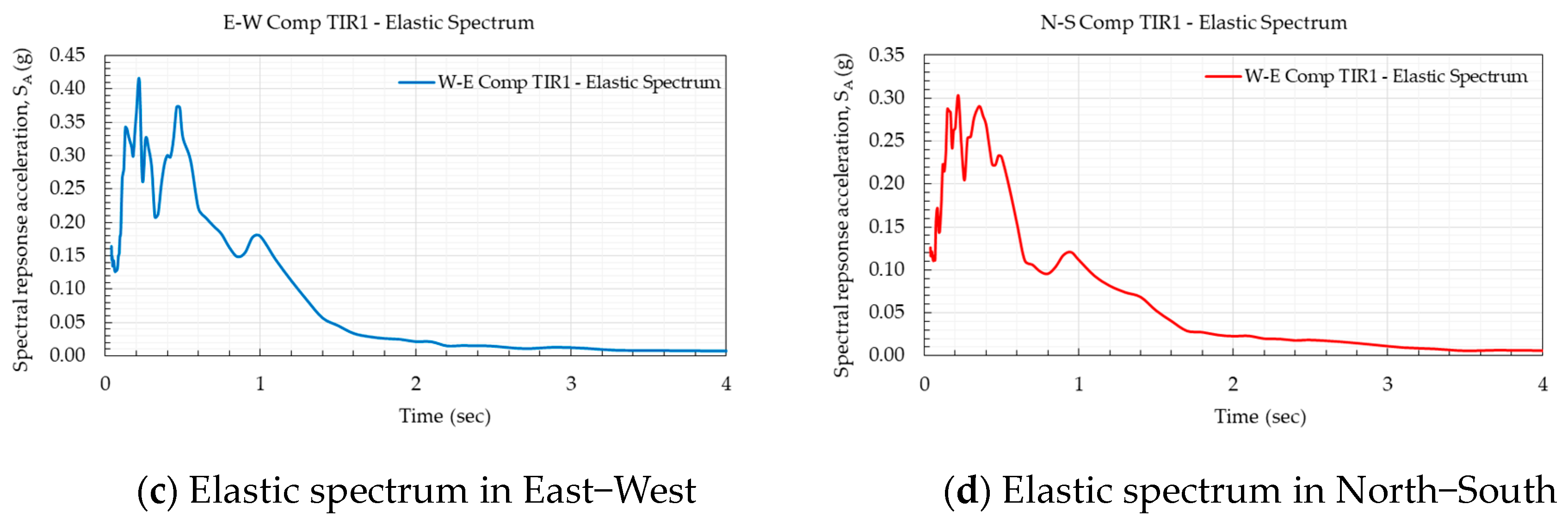
Seven monitoring stations (www.geo.edu.al (accessed on 8 January 2024)) detected a significant earthquake on 26 November 2019 (M = 6.4), spanning an epicentral distance range of 15 to 130 km [24]. Figure 3 illustrates the recorded ground motions in Tirana, displaying both the (N-S) and (E-W) directions (accelerometric station TIR1, 33.7 km from the epicenter). As shown in Figure 3, the horizontal peak ground acceleration is approximately 0.12 g, and in Durres, near the epicenter, this value was approximately 0.2 g [25].
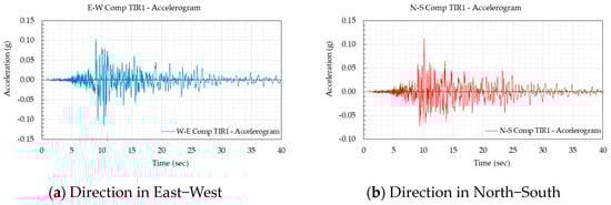

Figure 3.
Accelerograms and elastic spectra obtained from the earthquake that took place on November 26 (M = 6.4), 2019, as observed by the accelerometric station located in Tirana.
3.2.2. Flood Hazard
Table 3 presents the peak flow discharges observed at the bridge site for flood events characterized by different annual exceedance probabilities [26]. The annual peak discharge data are obtained from original studies of the project.
Table 3.
Local scour depths at bent foundations.
3.2.3. Local Scour at Bents Foundations Induced by Flood
In conducting an assessment of the multiple impacts of the case study bridge, flood occurrences for annual probabilities of exceedance of 20%, 10%, 5%, 2%, and 1% are studied. Bridge bent foundation scour depths, denoted as ys, are estimated using Equation (1). Table 3 gives the resulting values at all bent foundations. The slopes on both abutments have river protection, and no local scour is expected.
3.3. FE Modeling of Elements
The structure of the bridge is analyzed using CSIBridge v25.0.0 software. The effectiveness of the analytical model for the bridge relies on its elements’ functionality and interconnectivity. The FE model of the bridge shown in Figure 4 includes some assumptions and idealization, as described below. Characteristic values of materials are used as given in the project details. Concrete class C30/37 is used for reinforced concrete components and C45/55 for precast girders. The increment of existing concrete strength due to the aging of concrete is not considered. The steel class of B500C is used for reinforcing rebars. In the seismic analysis, the permanent masses of self-weight of structural elements, wearing surfaces, sidewalks, and barriers are considered, and the moving loads are excluded (EN1998-2) [22]. Also, referring to the research works carried out by Pietro et al. (2020, 2022) [9,10], the bridge is visually inspected, and it is concluded that the reinforced concrete elements and precast girders have adequate concrete cover and no exposed steel rebars are observed. So, the influence of corrosion induced by the carbonation phenomenon is not considered in the analysis.

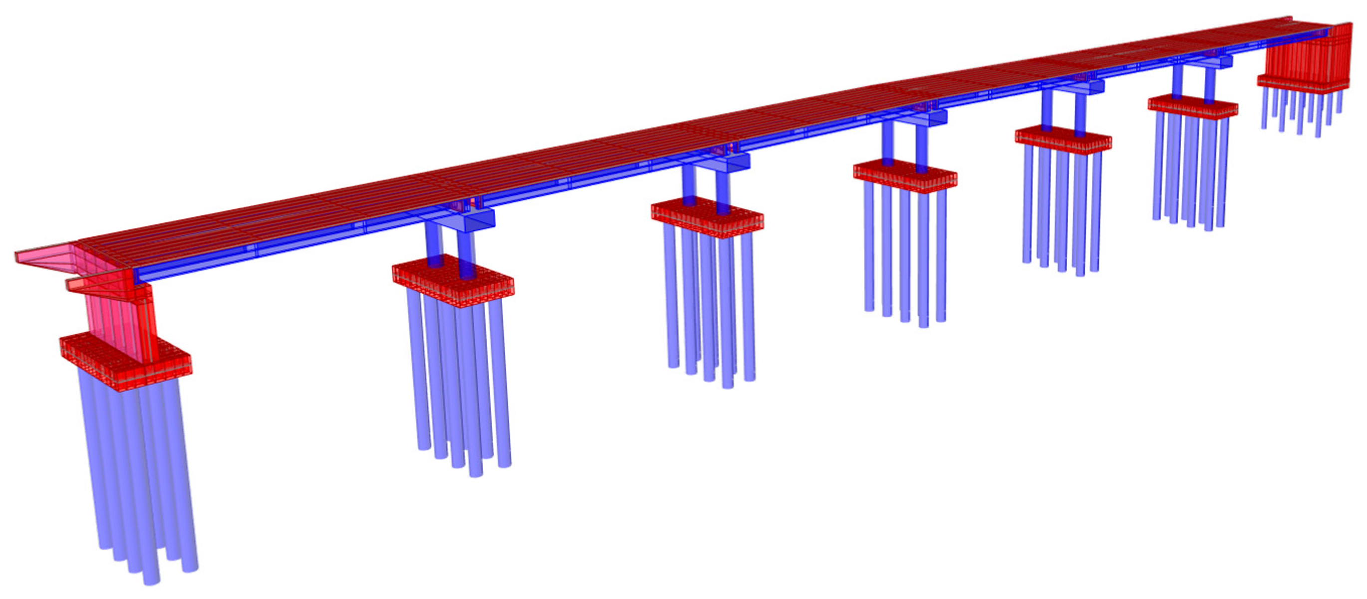
Figure 4.
3D FE model of bridge built in CSIBridge v25.0.0 Software.
3.3.1. Superstructure
The superstructure comprises a composite section incorporating a cast-in-place reinforced concrete slab and precast post-tensioned girders, synergistically operating as a unified entity. The superstructure is anticipated to maintain its elasticity and remain undamaged during seismic events. The girders are linked to bent caps or abutments through spring elements. The modulus of elasticity of concrete is estimated according to Section 3.1 of EN 1992-1-1:2004 [27]. For the composite section of the superstructure, no stiffness reduction is applied. An ideal bond between steel rebars and concrete, ensuring that the structural components retain their planar configuration following the application of loads, is considered.
3.3.2. Bents
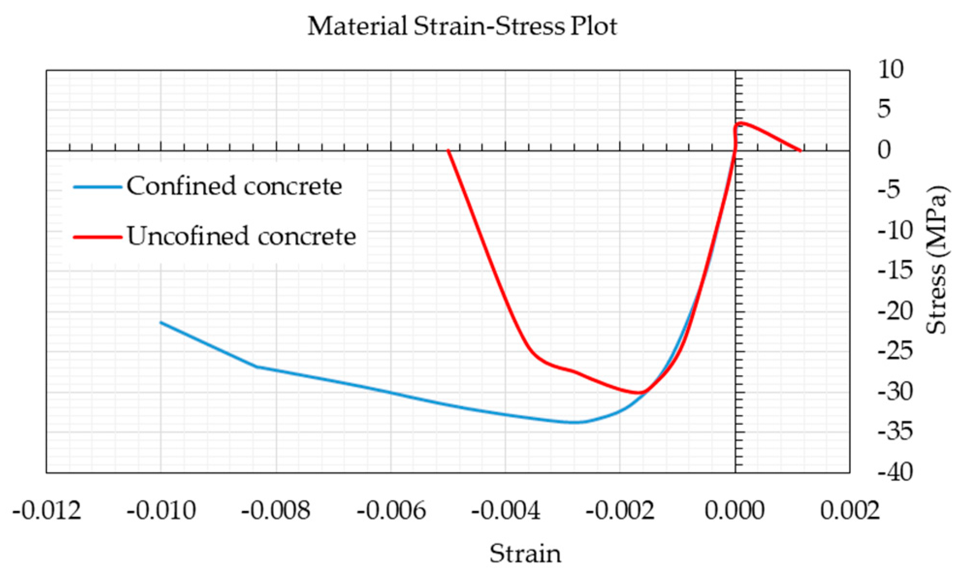
The bridge bents are made up of columns and cap beams. The orientation of the bents’ strong axes aligns with the bent’s transverse direction, attributed to the stiffness contributed by the cap beam with multiple column bents. Finite element discretization-based displacement is employed to perform nonlinear modeling of both bents and cap beams. The concrete material model proposed by Mander et al. (1988) [28] is utilized to define the stress–strain relations for unconfined and confined sections, shown in Figure 5.

Figure 5.
Material stress–strain plot for unconfined and confined concrete.
3.3.3. Abutments
The abutments interact with the earthfill behind the back wall. Therefore, soil structure is considered in abutment modeling. The space between the abutment wall and girders is represented utilizing elastic-perfectly plastic gap components. The backfill soil on the abutment wall is modeled as suggested by Caltrans (2013) [29], and for dynamic loading, the passive pressure will be raised by 50%. The abutment resistance in the bridge axis direction does not incorporate the influence of active soil pressure. Therefore, in the active direction, piles are the only resisting components. Spring elements are arranged in parallel along the bridge axis direction. The stiffness of the abutment wall is calculated using Equation (7).
Given the parameters, w represents the width and h signifies the height of the backwall. The backfill soil stiffness is taken as Ki = 14.35 kN/mm/m as proposed by Caltrans. The maximum passive pressure of 239 kPa given by Caltrans is increased by 50%, and 368 kPa of soil pressure is utilized for dynamic and earthquake loads. This pressure is utilized to calculate the passive pressure force opposing movement at the abutment:
3.3.4. Elastomeric Bearings
Under each precast post-tensioned girder of the superstructure, elastomeric bearings have been positioned and are considered free to move. The schematic models of the bridge components are shown in Figure 6. The horizontal stiffness of the elastomeric bearings is significantly lower when compared to the adjacent substructure and superstructure. In both horizontal directions, the elastomeric bearings demonstrate a behavior that can be accurately described using non-linear elements (elastic-perfectly plastic model). At the same time, the yield force aligns with the frictional force that arises at the interface between the concrete surface and the bearings. The bridge elastomeric bearings have a shear modulus of Gbearing = 0.90 N/mm2 with a friction coefficient set at 0.4 [30]. For this type of bridge, bearings are deemed sacrificial components, requiring inspection for damage and subsequent replacement in the aftermath of a significant seismic event.

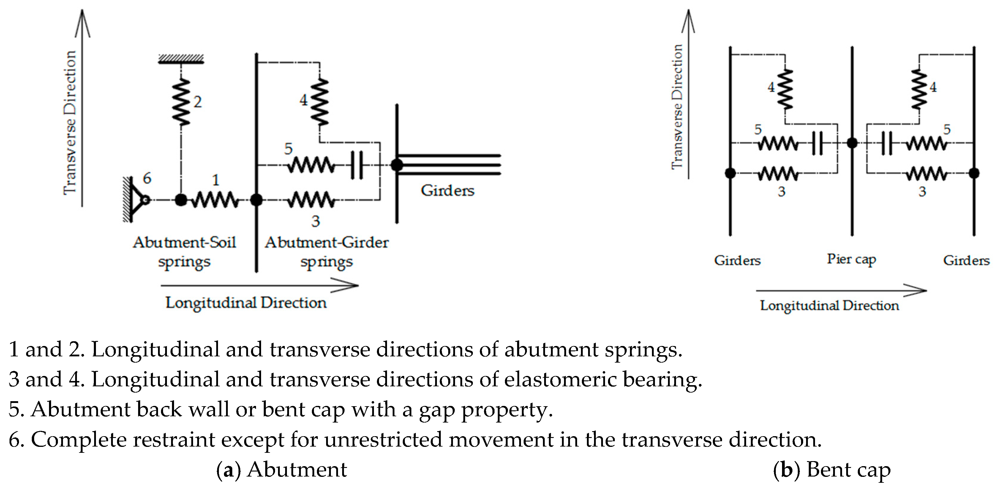
Figure 6.
Analytical model of the bridge components: (a) modeling of abutment; (b) modeling of bent cap (schematic model referring to details in original drawings).
3.3.5. Pounding Elements
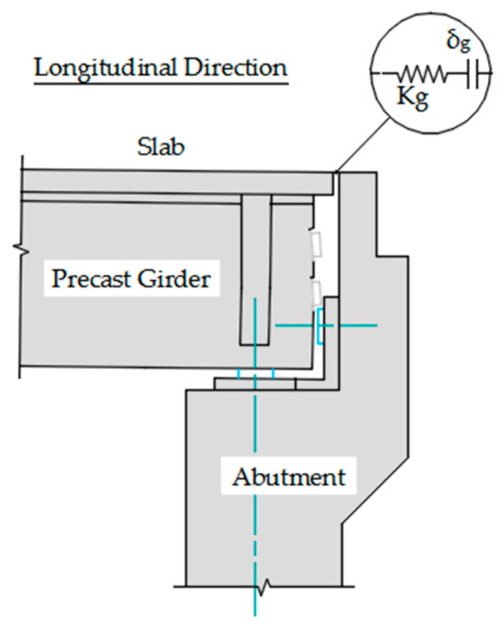
Pounded elements are utilized to simulate the collision among neighboring bridge superstructures or the bridge superstructure and the wall of abutments and piers in the bridge axis direction. For the lateral direction, pounding arises as the superstructure interacts with the concrete shear keys. The space distances for the pounding elements in both directions are set at 50 mm. Figure 7 illustrates the possible pounding location considered in the FE model analytically, taking into account the bridge’s amplified response due to the potential impact of structural elements (e.g., slab and back wall of abutment).

Figure 7.
Pounding location at the abutment under seismic actions (schematic model referring to the original drawings used in the FE model).
3.3.6. Foundations
The connection points between the soil and structure are depicted using a collection of non-linear soil springs distributed along the foundation piles and modeled using p-y spring elements for both horizontal directions. In contrast, the pile’s bottoms are fixed.
3.4. Non-Linear Time History Analysis
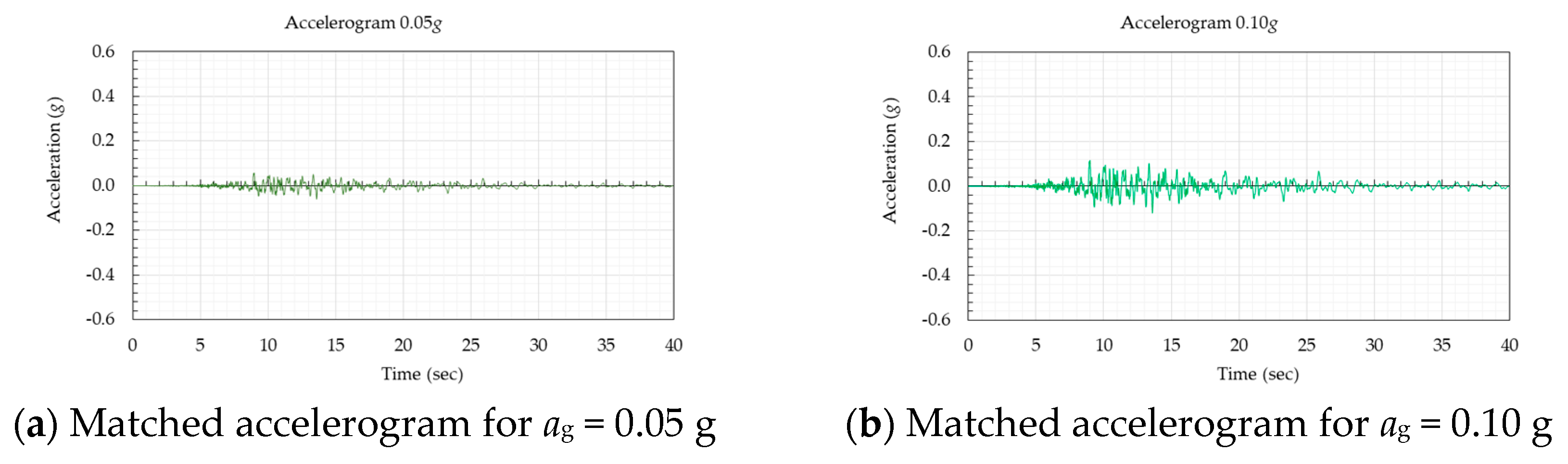
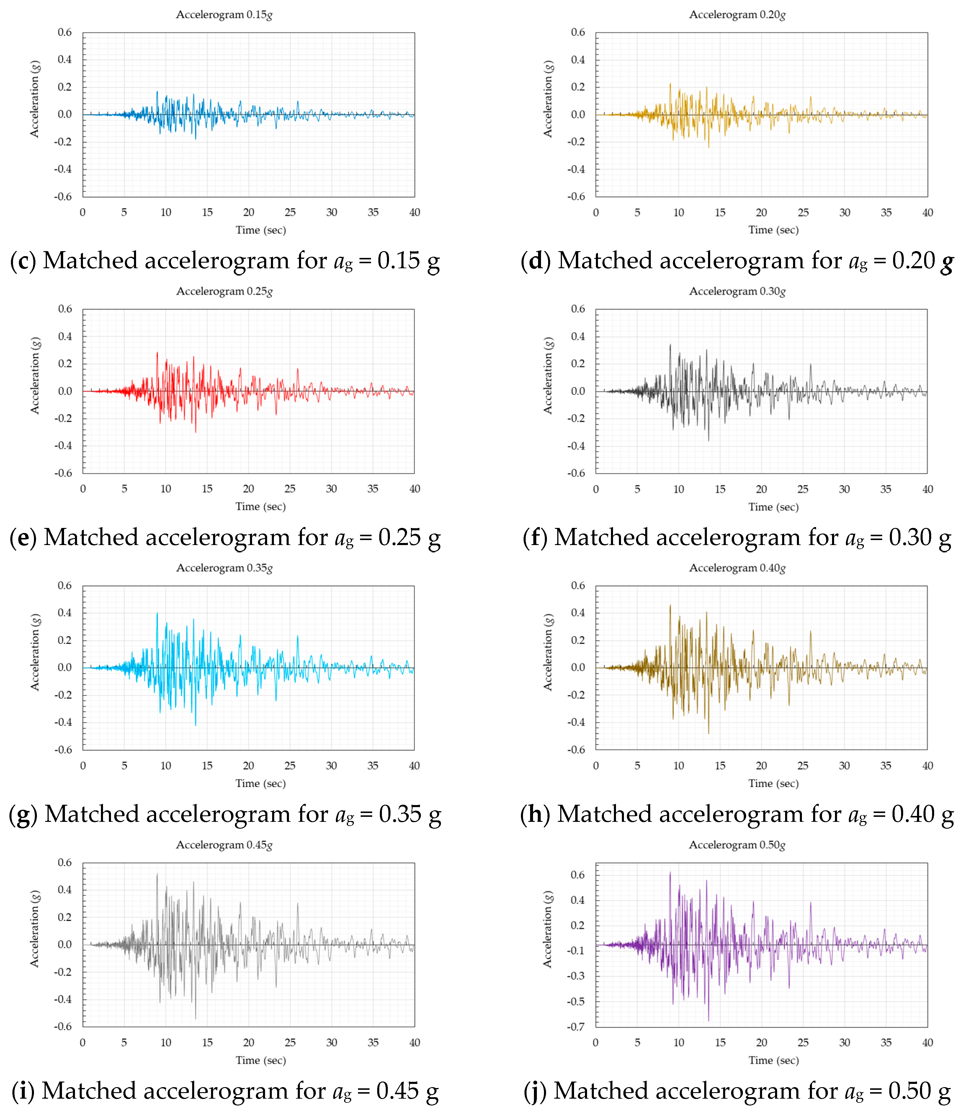
The bridge undergoes nonlinear time history analyses to assess its behavior under the ground motions generated as described above for different seismic levels by matching the real accelerogram of the Durres earthquake of Mw 6.4 to the target response spectrum with different seismic levels of Eurocode 8, as presented in Appendix A.
4. Results
In this paper, a multi-span, simply supported concrete girder bridge, which is the most common bridge type in Albania, is analyzed. The bridge is modeled with finite elements in CSIBridge v25.0.0 software and considers soil–structure interactions for different local scour depths and seismic levels. Then, the fragility curves are generated by utilizing the gathered analysis output data for the key elements.
4.1. Modal Analysis of Bridge
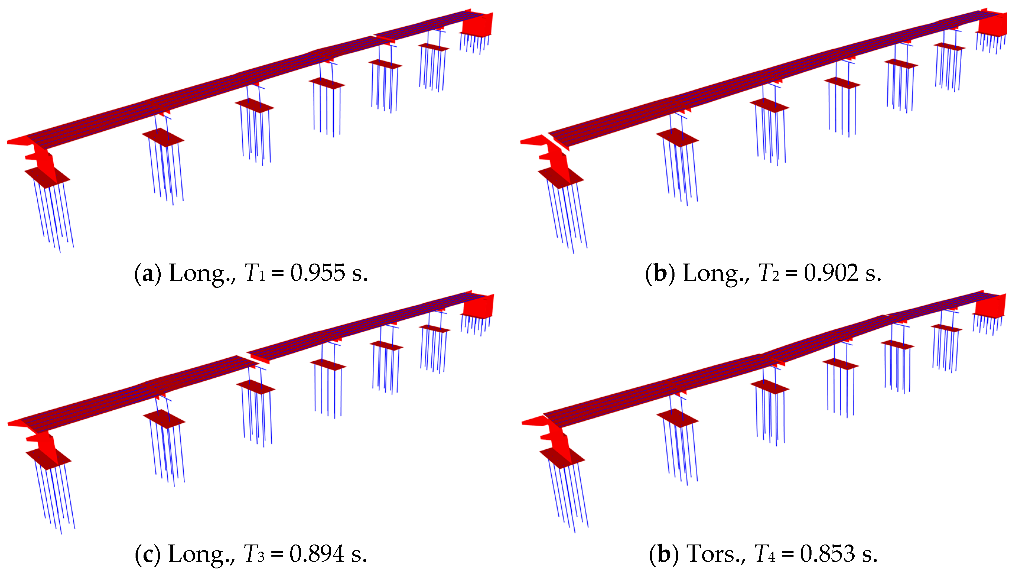
The bridge is analyzed in its original state. Figure 8 illustrates the fundamental mode shapes in the actual condition. Table 4 gives the fundamental modal periods for all levels of flood probabilities of exceedance. The permanent masses of self-weight of structural elements, wearing surfaces, sidewalks, and barriers are considered. The bridge is assessed with normal traffic, and the quasi-permanent values of variable actions are taken to be equal to zero.

Figure 8.
Fundamental periods of bridge.
Table 4.
Fundamental modal periods.
Figure 8 shows that the bridge is dominated by a fundamental mode of vibration in the longitudinal direction due to the smaller stiffness of bent columns in this axis.
As the local scour depths increase, the modal periods also exhibit a corresponding slight increase. The pile foundations of the bridge have larger stiffness values than the bent columns, and the vibration modes show low sensitivity to increasing the local scour depths.
4.2. Generation of Fragility
4.2.1. Element-Level Fragility
Critical elements of the structure are subjected to seismic assessments at various depths of local scour to develop fragility curves, utilizing specific engineering demand parameters. Bents, abutments, and bearings are recognized as elements with a high damage potential. The threshold limits specified in Table 1 are utilized to compare the structural response of elements, aiding in determining the damage states of the bridge. The results of non-linear response history analyses, conducted under the influence of generated accelerograms at various seismic levels, are utilized to develop fragility curves at the element level. The maximum structural response for each ground motion of the bridge element is determined by identifying the absolute maximum from the response non-linear time history analysis for each ground motion, considering the relevant engineering demand parameters. In this research work, truncated incremental dynamic analysis is performed only up to the maximum intensity measure IMmax = 0.5 g, above which no further analyses are performed [12]. In the analysis of the bridge, n = 10 ground motions were applied, among which m motions led to collapse at IM (xj) values less than IMmax (xmax). Meanwhile, the remaining n − m ground motions did not result in collapse before the end of the analysis. The given data are assessed using the maximum likelihood method. Equation (9) provides the mathematical expression for estimating the fragility function parameters for a specific damage limit state.
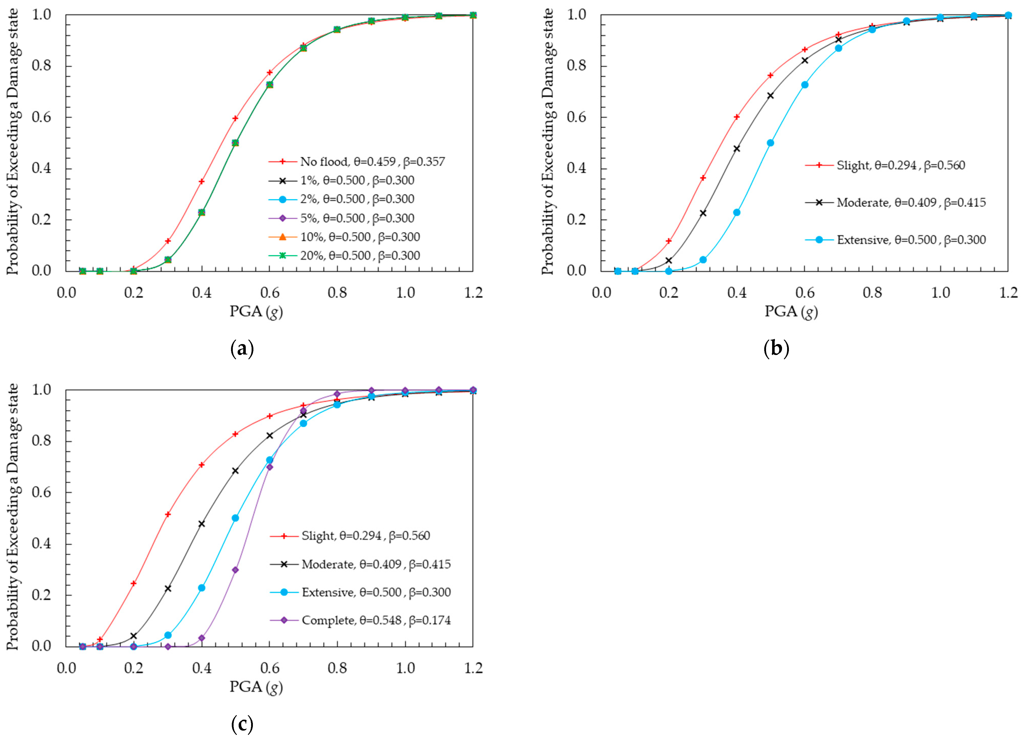
Figure 9 illustrates the fragility curves of structural elements at different local scour depths. The parameters, including median and log-normal values, are provided in these figures.

Figure 9.
Element-level fragility curve: (a) flexural damage of bent at complete state, (b) deformation of abutment wall, and (c) deformation of elastomeric bearing at longitudinal direction.
This figure highlights that bents are the sole elements of the bridge affected by seismic activity, regardless of the local scour depths, which could potentially lead to complete collapse. Variations in the fragility of the element are noted in the scenario without local scour compared to bents with varying scour depths at different flood hazard levels. The heightened bents with scour depths enhance the flexibility of bridge bents, consequently decreasing vulnerability to seismic actions in this bridge’s case.
4.2.2. System-Level Fragility Curves
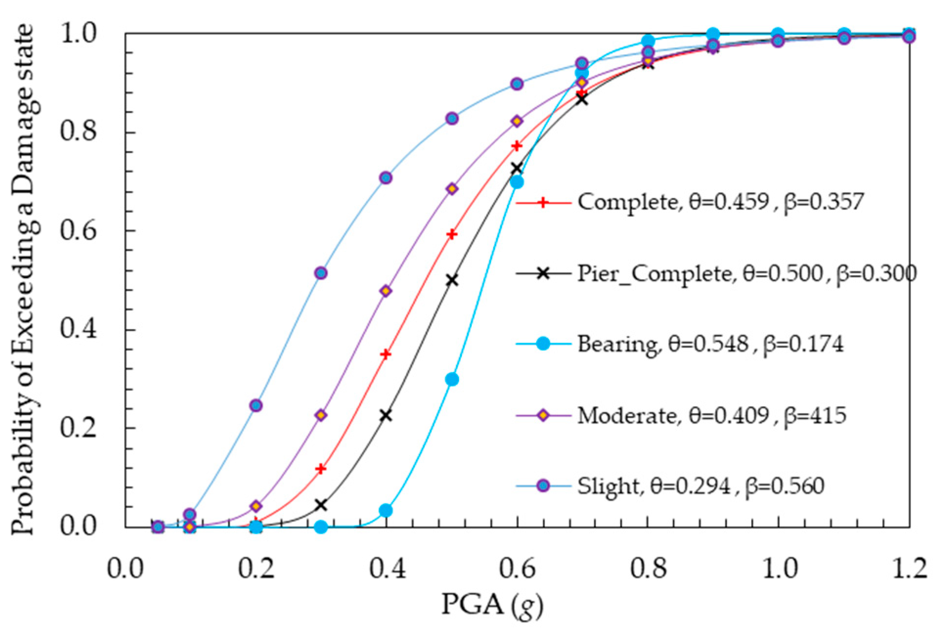
If a damage threshold is reached or exceeded by any individual part of the bridge, the entire structure is deemed to be in the same DS, irrespective of the conditions of other bridge elements. Figure 10 illustrates the bridge’s system-level fragility curves. Bent damage determines the complete damage state, while elastomeric bearings and abutments influence the extensive, moderate, and slight states. Additionally, increased local scour depth induced by flood events does not alter bridge seismic fragility.

Figure 10.
Fragility curves of bridge at the system level.
This paper emphasizes the importance of providing proper foundation stiffness and depth to reduce the possibility of bridge failure due to local scour induced by flood events in areas prone to earthquakes.
4.2.3. Fragility Surfaces
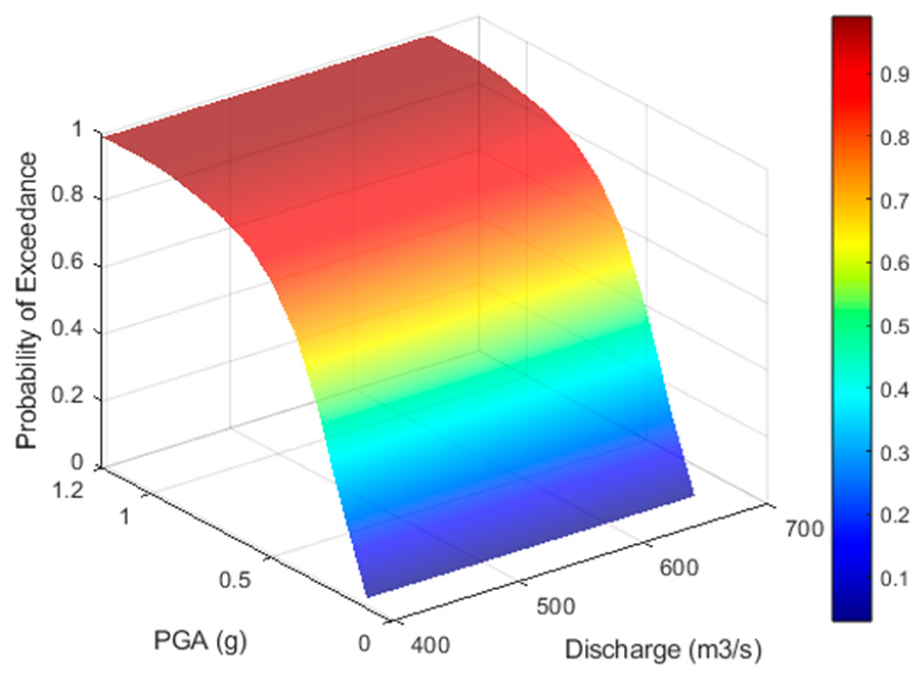
Figure 11 shows the fragility surfaces of the multiple impacts of seismic actions and floods treated as statistically independent random variables. The fragility surfaces are generated using the parameters outlined in Table 5 and mathematically estimated according to Equation (4). The formation of the fragility surface occurs exclusively when there is slight damage. Conversely, in the remaining three DS, no changes in the θ values of fragility curves are noted with increasing local scour depths induced by flood events. Consequently, the surfaces at these three DS extend linearly and represent the intensity measure of floods, following the respective fragility curves.

Figure 11.
Fragility surface of bridge at slight DS.
Table 5.
Values of θ and β at DS k.
The slight DS has notably small values of θ of flood hazard. This suggests a minimal impact of the multiple impacts of seismic actions and local scour induced by floods. The fragility analysis developed at the same damage conditions further supports this observation, demonstrating only small variations in bridge fragility characteristics.
4.3. Risk Evaluation
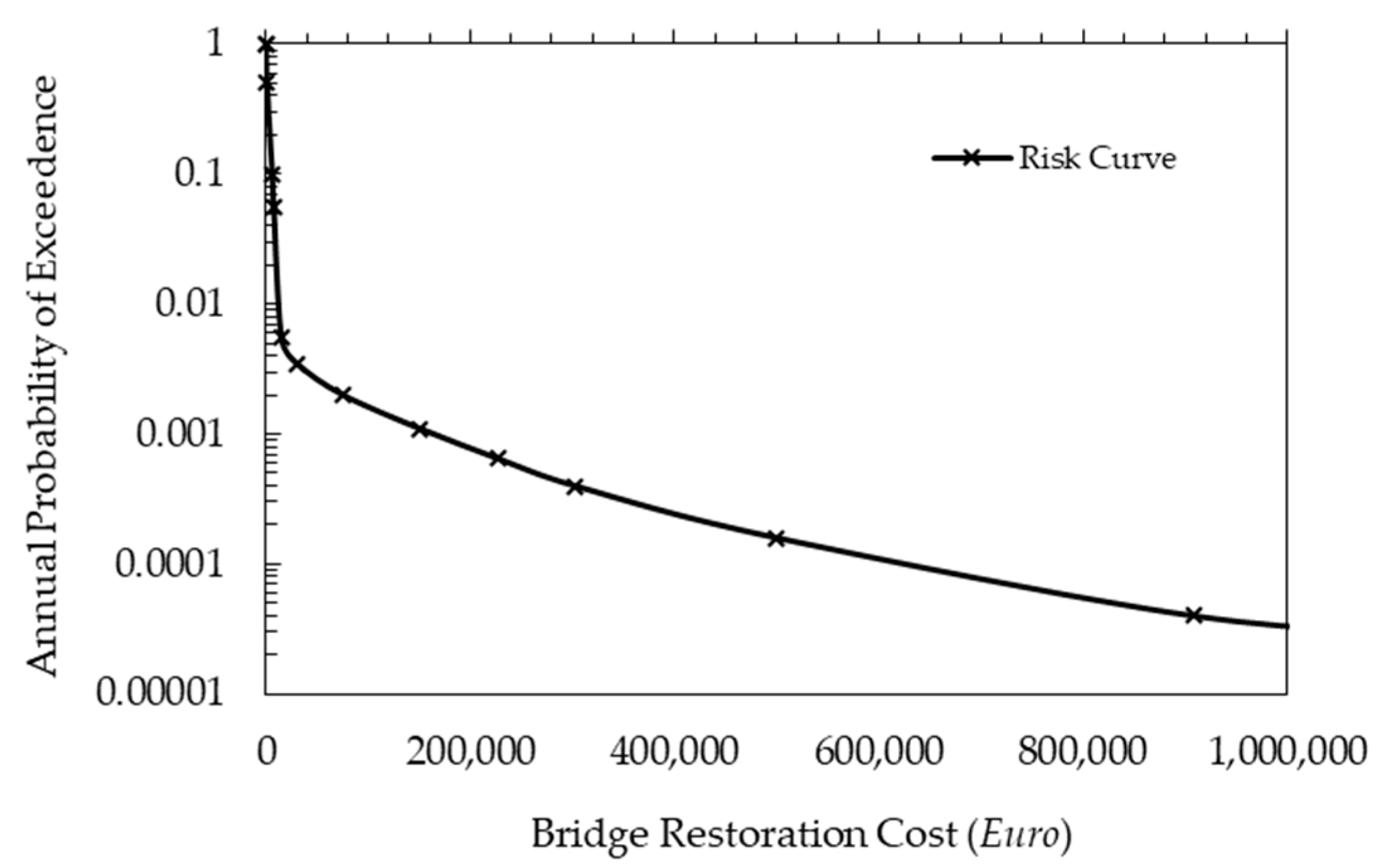
The average cost per unit area for construction of a new bridge of this type is 1150 Euro/m2. This is the average cost of constructing bridges at current prices for the same type of structure. Also, the real cost of the bridge built in 2013 is used as a reference. Figure 12 shows the risk curve for multi-hazard scenarios. The risk curve is generated using the information gathered from the fragility surface and curves and seismic hazard curves.

Figure 12.
Seismic risk curves of bridge.
In the case of the study bridge, there is no noticeable shift in the bridge risk curve as the local scour depth induced by floods increases. This lack of change is expected, as the bridge’s seismic fragility displays minimal sensitivity to scour induced by floods. In the case of slight DS, minor changes in the fragility curves of the bridge are noted for different scour depths. However, these changes are deemed insufficient to significantly alter the overall bridge risk curve.
5. Discussion
The presence of local scour induced by flood events can heighten the vulnerability of bridges imposed by later loads, such as that caused by an earthquake. Conversely, bridge flexibility might increase and help reduce earthquake load. However, the design philosophy and criteria used in the project could influence the overall safety of the bridge in scenarios involving local scour caused by flood hazards. In the last decade, several bridges in Albania, similar to the bridge under study, have had their foundations with piles uncovered by several meters due to the increase in flood events and, therefore, the increase in the risk of local scour. This situation significantly affects the structural stability of the bridge by causing a loss of lateral support at the foundations. Therefore, assessing the performance of the bridge for different local scour depths resulting from various annual peak flow discharges is crucial.
The results show that the fundamental periods of the bridge do not increase significantly with the scour depth, and this is due to the considerable stiffness of piles. The fragility curves of the study bridge for element and overall system levels, developed for multi-hazard scenarios, exhibit minor sensitivity to regional flood hazards. The bridge collapse is governed by the flexural failure of the bent (comprised of two columns each) due to seismic actions regardless of the local scour depths. A similar observation is also made by analyzing the graph of surface fragility and seismic curves. Also, the bridge is outfitted with elastomeric bearings, demonstrating reduced vulnerability to the harmful consequences of local scour. This is due to the damping characteristics and flexibility inherent in elastomeric materials. Additionally, the elastomeric bearings allow for greater adaptability to variations in load and movement. However, the increase in the local scour depth increases the probability of unseating the bridge superstructure in strong seismic activity.
The results are summarized as follows:
- The multi-span simply supported concrete bridge comprising elastomeric bearings and stiff foundations has low sensitivity to flood hazards.
- The seismic risk of a scoured bridge can be reduced by increasing the stiffness and depth of the foundations.
This study increases the attention of research communities and government agencies for the importance of studying bridges in areas prone to local scour induced by floods and earthquakes, which can be compounded by climate change. It will also serve as a basis for future research on implementing comprehensive bridge design that accounts for the potential impacts of earthquakes and changing climate conditions in multi-hazard scenarios, including the increased frequency and intensity of extreme weather events. Further research should focus on the impact of local scour induced by flood events on the seismic risk of these bridges (i.e., supported single or multi-span concrete bridges) and compare them with integral or continuous bridges. For the same type of bridge, the impact of foundation types on the bridge fragility will be of interest. It should also compare the components of the bridge that affect their functionality.
Author Contributions
Conceptualization, T.K. and J.C.M.; data curation, T.K., J.C.M. and N.-S.D.; formal analysis, T.K.; funding acquisition, T.K.; investigation, T.K.; methodology, T.K., J.C.M. and N.-S.D.; project administration, J.C.M.; resources, T.K.; software, T.K.; supervision, J.C.M.; validation, T.K.; visualization, T.K.; writing—original draft, T.K.; writing—review and editing, J.C.M., N.-S.D. and Y.X. All authors have read and agreed to the published version of the manuscript.
Funding
The paper is supported by the Project to Attract Foreign Experts (G2023133018L) from the Ministry of Science and Technology of China.
Institutional Review Board Statement
Not applicable.
Informed Consent Statement
Not applicable.
Data Availability Statement
The data presented in this study are available upon request from the corresponding author.
Conflicts of Interest
The authors declare no conflicts of interest.
Appendix A
Generated accelerograms used in time history analysis.
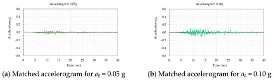

Figure A1.
Matched acceleration time histories.
Figure A1.
Matched acceleration time histories.
References
- Aliaj, S.; Koçiu, S.; Muço, B.; Sulstarova, E. Seismicity, Seismotectonics and Seismic Hazard Assessment in Albania; Academy of Sciences: Tirana, Albania, 2010. [Google Scholar]
- Nemry, F.; Demirel, H. Transport and Climate Change: A Focus on Road and Rail Transport Infrastructures. JRC72217 2012, EUR 25553 EN. Available online: https://publications.jrc.ec.europa.eu/repository/handle/JRC72217 (accessed on 27 January 2024).
- Arneson, L.A.M.; Zevenbergen, L.W.; Lagasse, P.F.; Clopper, P.E. Evaluating Scour at Bridges. Hydraulic Engineering Circular (HEC) No.18; Publication No. FHWA-HIF-12-003; Federal Highway Administration, U.S. Department of Transportation: Washington, DC, USA, 2012. Available online: https://www.fhwa.dot.gov/engineering/hydraulics/pubs/hif12003.pdf (accessed on 17 December 2023).
- Bennett, C.R.; Lin, C.; Parsons, R.; Han, J. Evaluation of behavior of a laterally loaded bridge pile group under scour conditions. In Proceedings of the SEI 2009 Structures Congress, Austin, TX, USA, 30 April–2 May 2009; pp. 290–299. [Google Scholar] [CrossRef]
- Avşar, Ö. Fragility Based Seismic Vulnerability Assessment of Ordinary Highway Bridges in Turkey. Ph.D. Thesis, Middle East Technical University, Ankara, Turkey, 2009. Available online: https://open.metu.edu.tr/handle/11511/18754 (accessed on 26 November 2023).
- Yilmaz, T. Risk Assessment of Higway Bridges under Multi-Hazard Effect of Flood-Induced Scour and Earthquake. Ph.D. Thesis, The Pennsylvania State University, University Park, PA, USA, 2015. Available online: https://etda.libraries.psu.edu/files/final_submisssions/10677 (accessed on 22 November 2023).
- NTC, Norme Tecniche per le Costruzioni, DM 17/01/2018 (In Italian). 2018. Available online: https://www.gazzettaufficciale.it/eli/gu/2018/02/20/42/so/8/sg/pdf (accessed on 1 December 2023).
- Clarke, J.; O’Brien, E. A multi-hazard risk assessment methodology, stress test framework and decision support tool for resilient critical infrastructure. Transp. Res. Procedia 2019, 14, 1355–1363. [Google Scholar] [CrossRef]
- Crespi, P.; Zucca, M.; Valente, M. On the collapse evaluation of existing RC bridges exposed to corrosion under horizontal loads. Eng. Fail. Anal. 2020, 116, 104727. [Google Scholar] [CrossRef]
- Crespi, P.; Zucca, M.; Valente, M.; Longarini, N. Influence of corrosion effect on the seismic capacity of existing RC bridges. Eng. Fail. Anal. 2022, 140, 106546. [Google Scholar] [CrossRef]
- Wang, Z.; Dueñas-Osorio, L.; Padgett, J.E. Influence of scour effects on the seismic response of reinforced concrete bridges. Eng. Struct. 2014, 76, 202–214. [Google Scholar] [CrossRef]
- Baker, J.W. Efficient analytical fragility function fitting using dynamic structural analysis. Earthq. Spectra 2015, 31, 579–599. [Google Scholar] [CrossRef]
- Nielson, B.; DesRoches, R. Analytical seismic fragility curves for typical bridges in the central and southeastern united states. Earthq. Spectra 2007, 23, 615–633. [Google Scholar] [CrossRef]
- Argyroudis, S.; Mitoulis, S.; Winter, M.; Kaynia, A. Fragility of transport assets exposed to multiple hazards: State-of-the-art review toward infrastructural resilience. Reliab. Eng. Syst. Saf. 2019, 191, 106567. [Google Scholar] [CrossRef]
- Ramanathan, K.N. Next Generation Seismic Fragility Curves for California Bridges Incorporating the Evolution in Seismic Design Philosophy. Ph.D. Thesis, Georgia Institute of Technology, Atlanta, GA, USA, 2012. Available online: https://repository.gatech.edu/server/api/core/bitstreams/1ec64ecb-b5e2-435d-ace3-e5ff0d3c0560/content (accessed on 6 January 2024).
- Stefanidou, S.; Kappos, A. Methodology for the development of bridge-specific fragility curves. Earthq. Eng. Struct. Dyn. 2017, 46, 73–93. [Google Scholar] [CrossRef]
- Atik, L.; Abrahamson, N. An improved method for nonstationary spectral matching. Earthq. Spectra 2010, 26, 601–617. [Google Scholar] [CrossRef]
- Shinozuka, M.; Feng, M.Q.; Lee, J.; Naganuma, T. Statistical analysis of fragility curves. J. Eng. Mech. 2000, 126, 1287–1296. [Google Scholar] [CrossRef]
- Zhou, Y.; Banerjee, S.; Shinozuka, M. Socio-economic effect of seismic retrofit of bridges for highway transportation networks: A pilot study. Struct. Infrastruct. Eng. 2010, 6, 145–157. [Google Scholar] [CrossRef]
- Federal Emergency Management Agency (FEMA). Hazus Earthquake Model Technical Manual: HAZUS 5.1. Washington, DC, USA. 2022. Available online: https://www.fema.gov/sites/default/files/documents/fema_hazus-earthquake-model-technicalmanual-5-1.pdf (accessed on 15 December 2023).
- Kuka, N.; Duni, L.; Koçi, R.; Dushi, E.; Xhahysa, A. Probabilistic Seismic Hazard Assessment of Albania; Department of Seismology, Institute of Geosciences: Tirana, Albania, 2020; Available online: https://www.geo.edu.al/rc/doc/New_PSHA_for_Albania_5460.pdf (accessed on 15 December 2023).
- EN 1998-2:2005; Eurocode 8—Design of Structures for Earthquake Resistance—Part 2: Bridges. European Committee for Standardization: Brussels, Belgium, 2005; pp. 44, 50.
- EN 1998-1:2004; Eurocode 8—Design of Structures for Earthquake Resistance—Part 1: General Rules, Seismic Actions and Rules for Buildings. European Committee for Standardization: Brussels, Belgium, 2004; p. 37.
- Duni, L.; Theodoulidis, N. Short Note on the November 26, 2019, Durres (Albania) M6. 4 Earthquake: Strong Ground Motion with Emphasis in Durrës City. EMSC Online Rep. 2019. Available online: https://www.ssis.org.al/wp-content/uploads/2020/01/Short-Note_EMSC_Duni-Theodoulidis-1.pdf (accessed on 2 December 2023).
- Freddi, F.; Novelli, V.; Gentrile, R.; Veliu, E.; Andreev, S.; Andonov, A.; Greco, F.; Zhuleku, E. Observations from the 26th November 2019 Albania earthquake: The earthquake engineering field investigation team (EEFIT) mission. Bull. Earthq. Eng. 2021, 19, 2013–2044. [Google Scholar] [CrossRef]
- Kolaneci, M.; Jegeni, T. Climatic and hidrological conditions of road “Urake to Ura e Shoshajve”. Tirana, Albania. 2009. [Google Scholar]
- EN 1992-1-1:2004; Eurocode 2—Design of Concrete Structures—Part 1-1: General rules and Rules for Buildings. European Committee for Standardization: Brussels, Belgium, 2004; p. 29.
- Mander, J.B.; Priestley, M.J.N.; Park, R. Theoretical stress-strain model for confined concrete. J. Struct. Eng. 1988, 114, 1804–1826. [Google Scholar] [CrossRef]
- Caltrans, California Department of Transportation. Seismic Design Criteria Version 1.7. Sacramento, CA; 2013. Available online: https://dot.ca.gov/-/media/dot-media/programs/engineering/documents/seismicdesigncriteria-sdc/f0007585seismicdesigncriteriasdc17fullversionoeereleasea11y.pdf (accessed on 26 November 2023).
- Caltrans, California Department of Transportation. Seismic Design Criteria Version 2.0. Sacramento, CA; 2019. Available online: https://dot.ca.gov/-/media/dot-media/programs/engineering/documents/seismicdesigncriteria-sdc/202007-seismicdesigncriteria-v2-a11y.pdf (accessed on 26 November 2023).


Disclaimer/Publisher’s Note: The statements, opinions and data contained in all publications are solely those of the individual author(s) and contributor(s) and not of MDPI and/or the editor(s). MDPI and/or the editor(s) disclaim responsibility for any injury to people or property resulting from any ideas, methods, instructions or products referred to in the content. |
© 2024 by the authors. Licensee MDPI, Basel, Switzerland. This article is an open access article distributed under the terms and conditions of the Creative Commons Attribution (CC BY) license (https://creativecommons.org/licenses/by/4.0/).