Article

Pathway to Carbon Neutrality in the Cement Industry: CO2 Uptake by Recycled Aggregates from Construction and Demolition Waste

by
David Bastos
1,
Catarina Brazão Farinha
2,*,
Cinthia Maia Pederneiras
1,2,3,
Rosário Veiga
2,
José Alexandre Bogas
3,
Ricardo Infante Gomes
2,3 and
António Santos Silva
2
1
c5Lab–Sustainable Construction Materials Association, Edifício Central Park, Rua Central Park 6, 2795-242 Linda-a-Velha, Portugal
2
LNEC–National Laboratory for Civil Engineering, Av. do Brasil 101, 1700-066 Lisbon, Portugal
3
CERIS–Instituto Superior Técnico, University of Lisbon, Av. Rovisco Pais 1, 1049-001 Lisbon, Portugal
*
Author to whom correspondence should be addressed.
Appl. Sci. 2024, 14(12), 5224; https://doi.org/10.3390/app14125224
Submission received: 15 May 2024 / Revised: 9 June 2024 / Accepted: 14 June 2024 / Published: 16 June 2024
(This article belongs to the Special Issue Recent Advances in Construction and Demolition Waste Recycling)

Abstract

:
Cementitious materials can capture CO2 through carbonation reaction during their service life and post-demolition. Indeed, construction and demolition waste (CDW) still have some potential for carbonation as they contain concrete and cement-based mortars. This research consists of an experimental programme to evaluate the CO2 capture of recycling aggregates (RAs) from CDW. Two types of CDW were studied, namely mixed recycled aggregates (MRAs) and recycled concrete aggregates (RCAs). The recycled aggregates were submitted to forced and accelerated carbonation at 23 °C, 60% relative humidity and 25% of CO2 concentration. This study contributes to the existing literature by investigating more realistic RA sources that have already absorbed atmospheric CO2 during their service life. From the experimental campaign, the results show that RCAs have higher carbonation potential when compared to MRAs due to the higher cementitious material content (Rc) and to the degree of natural carbonation. The recycled aggregates’ maximum CO2 capture was assessed by thermogravimetric analysis (TGA) at different CO2 exposure times. It was verified that the maximum CO2 capture, respectively, for MRAs and RCAs, occurred after 5 h and 12 h of exposition. In short, CDW captured from 5 wt.% to 35 wt.% of CO2 per tonne of cement paste, which corresponds to 0.6% to 4.1% per tonne of aggregate. It was concluded that the carbonation process of CDW has the potential to sequester from 123 kg to 225 kg of CO2 per tonne of cement paste for MRAs and 52 up to 491 kg of CO2 per tonne of cement paste for RCAs.

1. Introduction

The cement industry is a major contributor to high emissions of CO2 to the atmosphere, mainly due to the calcination of limestone to produce clinker. According to the International Energy Agency (International Energy Agency, 2024), the cement industry is the second most significant producer of global CO2 emissions. In addition, with the continuous growth of the human population, the demand for cement is set to rise between 12 and 23% by 2025 and it is expected that carbon emissions from the cement rise around 4%. To mitigate the CO2 emissions, different strategies can be considered, such as the use of alternative fuels (like biomass derivates of wastes), incorporation of different raw materials [1,2] and/or different manufacturing processes, as well as approaches to capture the released CO2 [3].
In this context, the carbonation of lime and cement-based materials is a promising strategy for capturing CO2. The carbonation of portlandite (Ca(OH)2) with the formation of calcium carbonate is dominant in these materials (Equation (1)), and it is an exothermic reaction [4]. The formation of CaCO3 within the pores of the cement matrix causes an increase in density and a decrease in water absorption [5,6]. In the presence of water and CO2, carbonic acid is formed (Equation (2)), decreasing the pH of the interstitial solution and causing the release of Ca2+ ions from hydrated cement compounds, leading to the formation of CaCO3 (Equation (3)). The reaction with CO2 also occurs with other hydrated phases of the cementitious material. At the limit, the carbonation of calcium silicate hydrate (C-S-H) leads to the formation of calcium carbonate and amorphous silica gel (Equation (4)). Other hydrated compounds like ettringite and calcium aluminates can be carbonated as well (Equations (5)–(9)) [7,8,9,10,11,12,13,14,15]. Ettringite in contact with CO2 forms calcium carbonate, gypsum and alumina gel. In addition, anhydrous compounds, like tricalcium silicate (alite) and dicalcium silicate (belite), can also be carbonated, producing calcium carbonate and, at the limit, silica gel.
C a ( O H ) 2 + C O 2 C a C O 3 + H 2 O
H 2 O + C O 2 H 2 C O 3  
H 2 C O 3 + C a ( O H ) 2 C a C O 3 + 2 H 2 O
C S H + C O 2 C a C O 3 + S i O 2 · α H 2 O
3 C a O . A l 2 O 3 . C a S O 4 .32 H 2 O + 32 H 2 C O 3 3 C a C O 3 + 2 A l 2 ( O H ) 3 . + 3 C a S O 4 .2 H 2 O + 23 H 2 O
C A H 10 + C O 2   C a C O 3 + A H 3 + 7 H 2 O
C 3 A H 6 + 3 C O 2   3 C a C O 3 + A H 3 + 3 H 2 O
3 C a O . S i O 2 + H 2 O + 3 C O 2 3 C a C O 3 + S i O 2 + H 2 O
2 C a O . S i O 2 + H 2 O + 2 C O 2 3 C a C O 3 + S i O 2 + H 2 O
Utilizing Construction and Demolition Waste (CDW) for CO2 sequestration can contribute to mitigating greenhouse gas emissions from the cement industry and also enhance the RA properties. This research aims to investigate the carbonation of several types of recycled aggregates (RAs) from different sources: recycling plants, in situ demolitions, and concrete industries (waste). An extensive experimental campaign was carried out, the methodology involves subjecting the selected RAs to a rich CO2 concentration environment promoting forced carbonation under determined reaction conditions (including temperature, humidity, and CO2 concentration), followed by the analysis of CO2 uptake exhibited by each RA at different exposure times. In most of the studies in the literature review, carbonated recycled aggregates come from concrete produced in a laboratory. Therefore, they do not represent the real CO2 capture of cementitious materials after their service life. This study complements the literature since it investigates other more realistic sources of RAs that have already been subjected to atmospheric CO2 during their service life. To achieve zero emissions in the cement sector, several strategies to mitigate the CO2 emissions have been investigated, and one of the alternatives is a process known as (re)carbonation, which permanently stores the CO2, providing a stable long-term solution. Therefore, this paper investigates the CO2 uptake of recycled aggregates from diverse sources of construction and demolition waste.

2. Research Significance

2.1. Environmental Parameters Affecting Carbonation Reaction

The carbonation of RCAs is mainly affected by relative humidity, temperature, CO2 concentration and CO2 pressure. In the carbonation reaction, the CO2 is first dissolved (solvation) in water, forming carbonic acid. Then, the carbonic acid is dissociated into hydrogen ions and bicarbonate ions, which will react with calcium cations forming calcium carbonate [13,14]. However, a high water content leads to the saturation of capillary pores, reducing the diffusion rate of CO2 and, hence, the degree of carbonation [14]. Therefore, there is an optimal range of relative humidity (RH) in which the carbonation rate is maximized.
From the literature, the maximum carbonation rate of concrete is reported at 50–70% RH [16,17,18]. In fact, various studies point to circa 60% of relative humidity as an ideal value [19,20]. Below 50% RH, the carbonation reaction is unlikely to occur [21], and above 70%, the small pores are likely to be filled with water, preventing carbonation from occurring [22,23].
Taking into account a wide range of concrete strength classes, Liu et al. [20] and Elsalamawy et al. [18] found that maximum carbonation rates are obtained at 65–70% RH. According to the results of Liu et al. [20], this optimal range was independent of the strength class of concrete. The maximum carbonation depths were achieved at 70% RH, for a temperature of 20 °C and a CO2 concentration of 20%. Naturally, concretes of lower strength classes, with higher porosity and less carbonatable products, presented the highest carbonation depth [20]. A similar trend was reported by Elsalamawy et al. [18], for concretes with CEM I 42.5 N and CEM III/A 42.5 N, with and without silica fume.
Fang et al. [24] evaluated the forced carbonation of RCAs under 5%, 50% and 95% relative humidity (RH) and 100% CO2 concentration. It was found that the highest CO2 capture of RCAs was obtained at 50% RH. In this case, the CO2 capture after 24 h was around 12 kg per 1 tonne of RCAs. The authors have evidenced that the carbonation reaction did not occur at 5% nor at 95% relative humidity.
Temperature affects carbonation and hydration reactions. In the work of Liu et al. [20], the effect of temperature was investigated between 10 °C and 30 °C on the carbonation process of cement pastes. The authors reported that the carbonation depth of concrete increased with temperature, i.e., a higher carbonation rate as temperature increases [25].
Hyvert et al. [26] developed an elementary model to predict the carbonation of mortars under various CO2 partial atmospheric pressures, namely 0.03%, 10%, 25% and 50%. Three types of normalized mortars at seven exposure times were considered. The results of the X-ray diffraction (XRD) analysis indicated that the carbonation of portlandite, ettringite and hydrated calcium aluminates were extensively carbonated at low CO2 pressure. However, it was found a significant reduction in the porosity of the carbonated zone when higher pressures were implemented, meaning a higher carbonation degree. It was also found that the C-S-H carbonation rate is widely dependent on the pressure. Ye et al. [27] studied the C-S-H and cement paste carbonation at different air pressure (0.1, 0.15 and 0.2 MPa). It was concluded that, under the same carbonation time, the carbonation depth increased with the air pressure.
Lyubomirskiy et al. [28] studied the influence of temperature on the forced carbonation speed of lime, considering the effect of different CO2 pressures (above atmospheric values). It was concluded that with the increase in pressure the effect of temperature in the carbonation reaction becomes less relevant. Nevertheless, the carbonation rate increased with temperature. This effect can be explained by the fact that at high pressure, the volume of CO2 adsorbed in the surface of the material is much higher than the volume at lower pressures, promoting a faster interaction between the compounds that can carbonate. As mentioned, a higher carbonation rate can lead to the formation of carbonated “barriers” on the surface of the materials, decreasing CO2 diffusion and the speed of carbonation.
The use of high concentrations allows more CO2 to diffuse into concrete, increasing the carbonation depth and the respective carbonation rate. However, at high concentrations of CO2, pore clogging can occur more easily due to the formation of more carbonates, affecting CO2 diffusion. According to some authors, the ideal CO2 concentration to maximize the carbonation process is around 20–30% [29,30]. Cui et al. [31] studied three different concretes exposed to different CO2 concentrations, namely 2%, 10%, 20%, 50% and 100%, at different periods of time (7, 14, 28 and 56 days). The results indicate that the carbonation depth increased until 20% of CO2 concentrations. Above 20%, the “clogging” effect affected the microstructure, reducing the CO2 diffusion into concrete.
Castellote et al. [32] studied the chemical changes and phase analysis of Portland cement pastes exposed to different CO2 concentrations (3%, 10% and 100%) and compared it with natural carbonation (0.03%) after a specified carbonation time. For 3% of CO2 concentration, the formed phases were similar to those from natural carbonation. This conclusion was obtained by comparing the Ca/Si ratio of the C-S-H gel of the uncarbonated sample (Ca/Si = 1.87), with that of C-S-H after 0.03% and 3% CO2 concentration. The Ca/Si of C-S-H was lower for 0.03% CO2, but this compound was not totally consumed by carbonation (Ca/Si = 1.23 and 1.18 for 0.03% and 3% CO2, respectively). However, at 10% and 100% concentration of CO2, the C-S-H gel decomposed due to the progressive depolymerization of C-S-H (that increases with CO2 concentration) and the formation of Ca-modified silica gel and calcium carbonate. Moreover, when carbonating at 0.03% and 3% CO2, there was still some evidence of ettringite content, which means that it did not fully react during carbonation. However, at 10% and 100% concentrations of CO2, no ettringite content was detected, suggesting that it was fully consumed after carbonation.

2.2. Effect of Carbonation on RCA Properties

Carbonation is reported to modify the microstructure of recycled concrete aggregates (RCAs), porosity and related properties. In well-hydrated cement-based materials, CO2 reacts with calcium hydroxide, as well as with calcium silicate and calcium aluminate hydrates, precipitating calcite in the pores [33]. This decreases the total porosity of RCAs [14,34,35], by reducing the pores diameter. The influence of carbonation in RCA microstructure varies according to the initial porosity of the aggregates. Chen et al. [34] investigated the carbonation of two samples with low and high porosity, respectively. From XRD analysis, the high-porosity samples showed a higher amount of CaCO3 formed than the low-porosity samples. In those with low porosity, a dense CaCO3 layer was formed near the surface and the CO2 could not penetrate the sample in depth. On the other hand, the carbonation in high-porosity specimens also occurred in deeper pores, because CO2 easily flowed through the pore system, forming a CaCO3 film along open pores. In this case, the porosity decreases and makes the CO2 diffusion more difficult, slowing down the carbonation reaction [34].
Some studies found in the literature point out a reduction of porosity with carbonation in cement-based materials. The reduction of porosity due to carbonation naturally increases the density of RCAs [14,16,17,35,36,37,38,39,40,41]. The increase in density depends on the initial characteristics of RCAs, namely porosity and carbonation potential. About 5–8% increase is reported when compared to the density of uncarbonated RCAs [42,43]. The increase in density will lead to lower absorption and higher mechanical strength of RCAs, bringing them closer to the characteristics of natural aggregates (NA).
In fact, usual RCAs are more porous than NA, which leads to higher water absorptions [44,45]. However, as mentioned, the porosity and water absorption of RCAs are reduced after carbonation [35,42,43,46,47]. Depending on the initial characteristics of RCAs, some researchers report a reduction of 20–28% in water absorption, after carbonation [17,42,43]. This reduction allows to reduce the amount of mixing water in cement-based materials and better control of their fresh properties.
Zhang et al. [36] studied the carbonation of RCAs with different-sized particles under 2.5 mm. The authors verified that the smaller particles carbonated faster than the larger ones due to the higher surface area of the aggregate. Additionally, it was reported that after carbonation, both CaCO3 and silica gel were formed, which increased the density of the RCAs and reduced their water absorption. In this work, the carbonation potential was not measured since the purpose of the study was to enhance the mechanical properties of RCAs.
Tam et al. [48] also investigated the carbonation of RCAs, aiming to improve their mechanical properties. Again, these authors did not focus on the CO2 uptake of the RCAs, but on improving RCA performance.
In the study of Xuan et al. [41], an accelerated carbonation technique was used to enhance the quality of recycled concrete aggregate. The authors studied the CO2 capture of two RCAs, one produced in the laboratory and another one from demolition concrete debris. The RCAs from the laboratory with particle sizes between 5 mm and 20 mm captured on average 7.9 kg of CO2 per tonne of aggregate. The RCAs from crushing debris sequestrated 5.2 kg of CO2 per tonne of aggregate. This reduction of RCA CO2 uptake was attributed to their previous natural carbonation during their service life.
The interfacial transition zone (ITZ) between the natural aggregates and the cement paste is a weak region of the RCAs. When the adhered old mortar shrinks may introduce microcracking in this ITZ [49], which reduces the mechanical strength of RCAs compared with natural aggregates. In this context, according to Lu et al. [42], carbonation can improve the ITZ of RCAs. The authors compared backscattered electron (BSE) images of uncarbonated and carbonated RCAs and concluded that uncarbonated RCAs presented a less compact ITZ than carbonated RCAs [42].
Li et al. [50] studied the ITZ of carbonated coarse RCAs, considering different particle sizes: 10–20, 20–30 and 30–40 mm. The samples were subjected to carbonation for periods of 7, 14 and 28 days. The authors concluded that the carbonation improved the physical properties of RCAs by modifying their morphology. Moreover, Li et al. [51] also found that the carbonation process enhanced both the original interfacial transition zone and the attached mortar in the RCAs, although the former experienced more significant enhancement than the latter. In both studies, the CO2 uptake was not measured.
The durability of the concrete produced with carbonated coarse RCAs was assessed by Russo et al. [52]. The authors reported that carbonated RCAs and the concrete produced with them performed better than noncarbonated ones.
To ensure structural longevity and to mitigate environmental consequences in construction practices, it is important to understand the carbonation potential of RAs and identify the minimum period in which maximum CO2 absorption occurs (optimal carbonation period). Gomes et al. [53] presented a review of all the variables that affect the carbonation process of CDW, namely temperature, relative humidity, CO2 concentration, exposition time and particle size of CDW. Based on several published works optimal conditions for the carbonation of CDW aggregates were defined.
This research aims to elucidate these aspects by studying various types of RAs with different sources. The approach used in this study consists of subjecting them to forced carbonation at different conditions (temperature, humidity and CO2 concentration) and carefully analysing the respective CO2 uptake of each RA. The existing literature is essentially focused on the carbonation of RCAs, aiming to improve its performance. In this work, however, the aim is to determine the CO2 uptake by recycled aggregate from construction and demolition waste to mitigate the CO2 emissions of the cement sector. In order for the study to be more comprehensive, mix–recycle aggregates (MRAs) are analysed in addition to RCAs, as they are the most common in the construction industry.

3. Materials and Methods

3.1. Materials

According to the legislation of the European Union concerning CDW management, CDW must be sent to recycling plants that are responsible for its treatment (Waste Framework Directive 2008/98/EC). In this study, 7 types of recycled aggregates (RAs) were collected directly from recycling plants, in situ demolitions and concrete industry wastes (Table 1). Concrete aggregates, with well-known compositions, were also produced in a laboratory to be compared with other recycled aggregates. The selected RAs were divided into the following categories: mixed recycled aggregates (based on a miscellany of rubble); recycled concrete aggregates (mainly composed of concrete and mortar waste); RAs from concrete samples produced in a laboratory (control concrete, CA-L).
In CA-L, the binder used was a cement type CEM II/A-L 42.5 R according to the EN 197-1 [54], having around 15% limestone filer. The concrete specimens produced with this cement were kept underwater to prevent natural carbonation. At about 3 months of age, the specimens were dried at 40 °C until constant mass; afterwards, the samples were grinded and sieved in order to produce a representative sample based on a granulometric curve to be analysed before and after CO2 exposure.
The constituents of RAs were classified based on the European standards EN 933-11 [55] and EN 13242 [56]. The procedure involves an initial separation of the floating parcels from the non-floating ones. Once the non-floating portion is obtained, the remaining portion is separated and classified into various constituents as stated in the standards.
The classification of RAs according to EN 933-11 [55] is also presented in Table 2. The CA-L is composed of 260 kg/m3 cement, 50 kg/m3 limestone filler and 1900 kg of coarse and fine aggregate. The cementitious fraction (Rc—concrete, concrete products, mortar and concrete masonry units) is the major component of the recycled aggregates, with emphasis on RCAs. This fraction has a direct influence on the carbonation effectiveness of the RAs from CDW. Therefore, it is expected that the greater the amount of Rc, the higher the carbonation potential of the sample. However, this potential is also affected by other factors, such as age, exposure and type of binder, which can reduce the fraction of carbonatable compounds in Rc. The recycled aggregates collected in recycling plants were in stockpiles exposed to the air, and it is not known where the material came from.
The test results of water absorption, particle density and apparent bulk density are shown in Table 3. It must be noted that, as expected by the results found in the literature, the recycled aggregates presented lower particle density and higher water absorption than natural aggregate.

3.2. Methods

The aggregates were selected and dried at 60 °C. Then, recycled aggregates were ground and sieved (according to the European Standard EN 1015-1 [57]) and only particles under 2 mm were subjected to forced carbonation. In fact, it was found that below 2 mm the amount of carbonatable substances is greater, improving the rate of CO2 uptake. Moreover, the recycled aggregates were aimed to be incorporated into cement mortars, and aggregates under 2 mm are the most adequate for this purpose. Finally, samples were divided in an automatic separator. Once the sampling process was completed, the samples were subjected to forced carbonation. The samples were placed individually in the respective sample holder (according to their assigned exposure time) with 8–10 g of sample and with a sample thickness of 1 cm or less in order to promote greater contact between the sample and the CO2 rich-environment. The samples were then placed in an ARALAB Fitoclima 300 EP carbonation chamber with the following test conditions: 23 °C, 60% RH and 25% CO2. After carbonation, the samples were sealed in plastic and stored in a desiccator until the post-carbonation analysis was carried out. The adopted CO2 concentration, temperature and relative humidity were based on a literature review, namely in the parameters suggested by Gomes et al. [53] regarding the best conditions optimize the CO2 uptake of CDW. The CO2 used presented 99.7% of purity. Different carbonation periods were tested, namely 3 h, 5 h, 8 h, 12 h and 24 h, in order to define the maximum CO2 capture of the RAs.
The aggregates were characterized through XRD and TGA, before and after each carbonation period, to determine the impact of carbonation on the mineralogy of RAs and the amount of CO2 uptake.

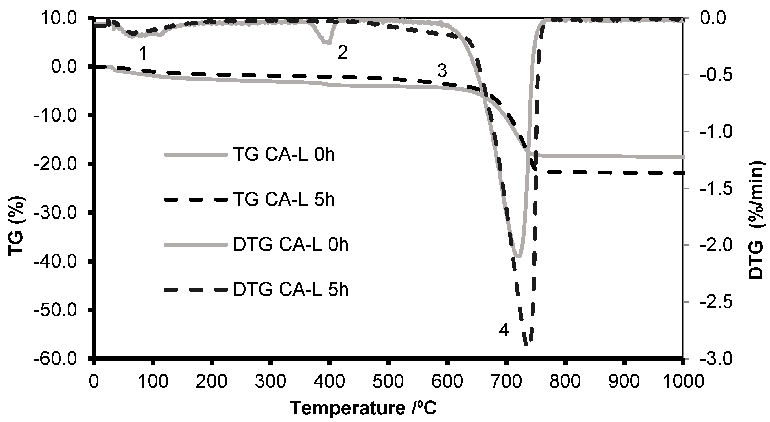
3.2.1. Thermogravimetric Analysis

The carbonation potential of recycled aggregates was assessed by TGA, using a SETARAM TGA92 simultaneous DTA-TGA thermal analyser and a HITACHI STA7200 apparatus. This test measures the mass loss of the samples while they are heated continuously from 25 to 1000 °C at a uniform rate of 10 °C min−1, with an argon atmosphere (3 L/h). The test conditions used, namely heating rate and temperature range, as well as the type of gas and flow rate, are those commonly used for the study of cementitious materials [58].
From the mass losses obtained during the test at different temperature ranges, it is possible to quantify the calcium hydroxide and calcite content of the sample and evaluate the degree of carbonation in cement-based materials. The calculation of the first derivative of the mass loss curve (DTG) for this specific type of material, usually shows peaks in three different temperature ranges (Z1, Z2 and Z3) [10,13]. Each range represents the mass loss due to certain compound’s decomposition:
  • Z1, [20–400 °C]: temperature range that corresponds to release of moisture and dehydration of hydrated calcium silicate (C-S-H) and calcium aluminate hydrates (AFt and AFm phases);
  • Z2, [400–500 °C]: temperature range that corresponds essentially to the dihydroxylation of portlandite (CH); allows to estimate the content of free portlandite, that can be used to estimate the carbonation potential of a cementitious material;
  • Z3, [500–900 °C]: temperature range that corresponds to carbonates decarbonation, allowing to estimate CaCO3 content.
Due to the high heterogeneity of RAs, samples of about 100 g were separated using an automatic rotary sample splitter apparatus. Subsequently, each sample was crushed in a mechanical grinding device until fine powders with particle size <106 μm were obtained.
TGA was used to evaluate the amount of CaCO3 formed and Ca(OH)2 remaining. The maximum CO2 uptake is determined by the difference between the calcium carbonate content of the noncarbonated samples (0 h) and the calcium carbonate content after the “ideal” carbonation period (Equations (10) and (11)).
C a C O 3 = ( C a C O 3   f i n a l C a C O 3 i n i t i a l )
% C O 2 u p t a k e = C a C O 3 × M M C O 2 M M C a C O 3
CaCO3initial is the CaCO3 content of uncarbonated samples and the CaCO3final corresponds to the maximum CaCO3 content obtained after carbonation, being M M C O 2 and MMCaCO3 the molecular weight of CO2 and CaCO3, respectively.

3.2.2. X-ray Diffraction Analysis

The XRD characterization was performed in complement to TGA to detect any alterations in cementitious compounds after carbonation, including the formation of different CaCO3 polymorphs. The XRD test was performed with an AERIS Malvern Panalytical X-ray diffractometer with 40 kV and 15 mA, using Copper Kα radiation (λ = 1.5406 Å). Diffractograms were recorded in the range of 5–85°2θ, at a step size of 0.20°/s. The XRD was made according to an internal procedure based on LNEC specification E 403:1993 [59] and using the HighScore Plus software version 4.0 from Malvern Panalytical and the Crystallography Open Database (COD) for the peak identification [60,61,62,63,64,65,66,67].

3.2.3. pH Evaluation

The pH of the recycled aggregates was measured to check whether there was an acid attack during the forced carbonation, which would cause a decrease in the calcium carbonate content. The analysis was performed using a METRIA portable pH meter model M21. This test involves placing the sample in a container with distillate water in a proportion of 1:1 (water: recycled aggregate) under magnetic agitation for 24 h. Afterwards, the pH probe is placed in the solution (water more sample), and its value is recorded.

4. CO2 Capture of RAs

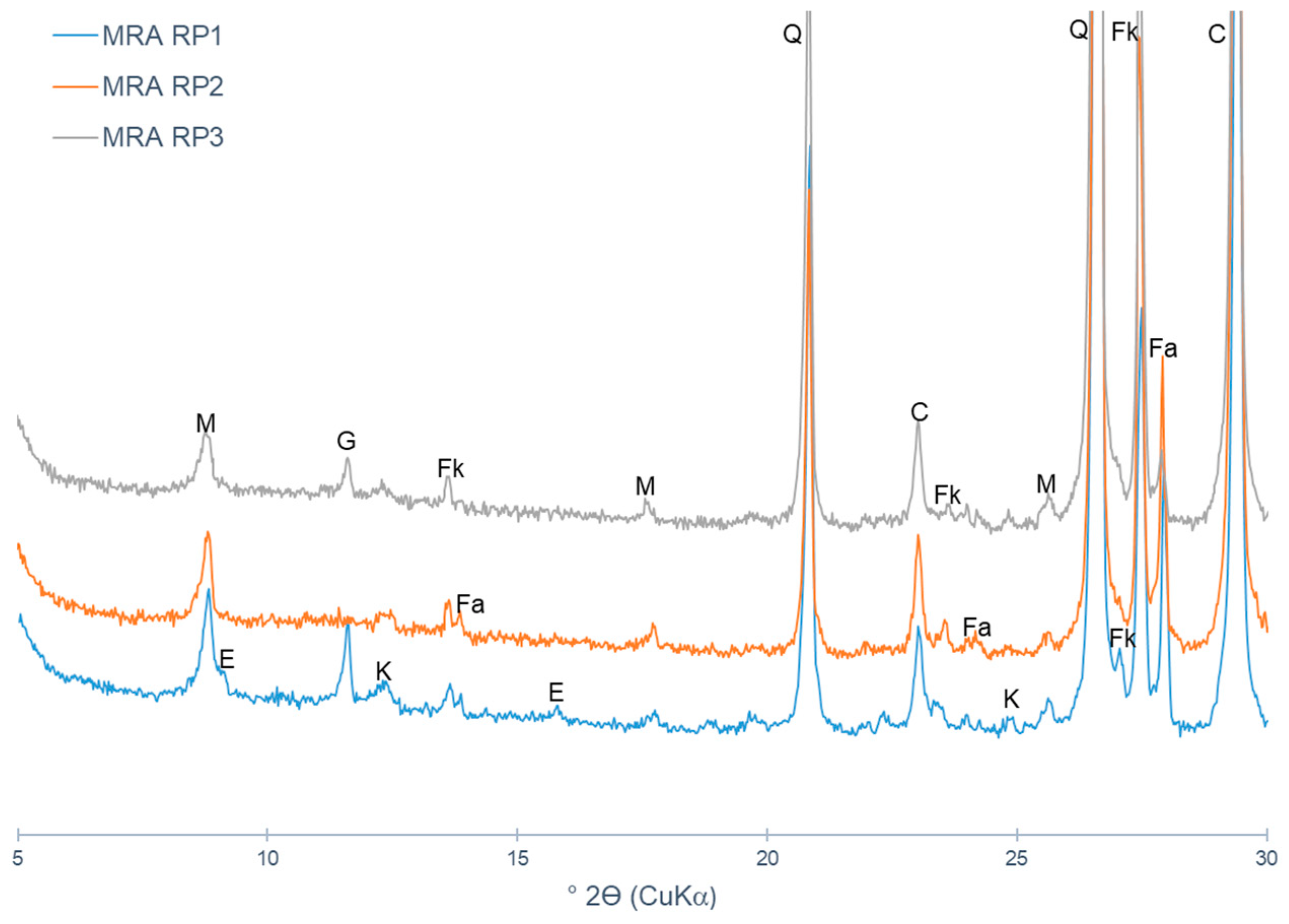
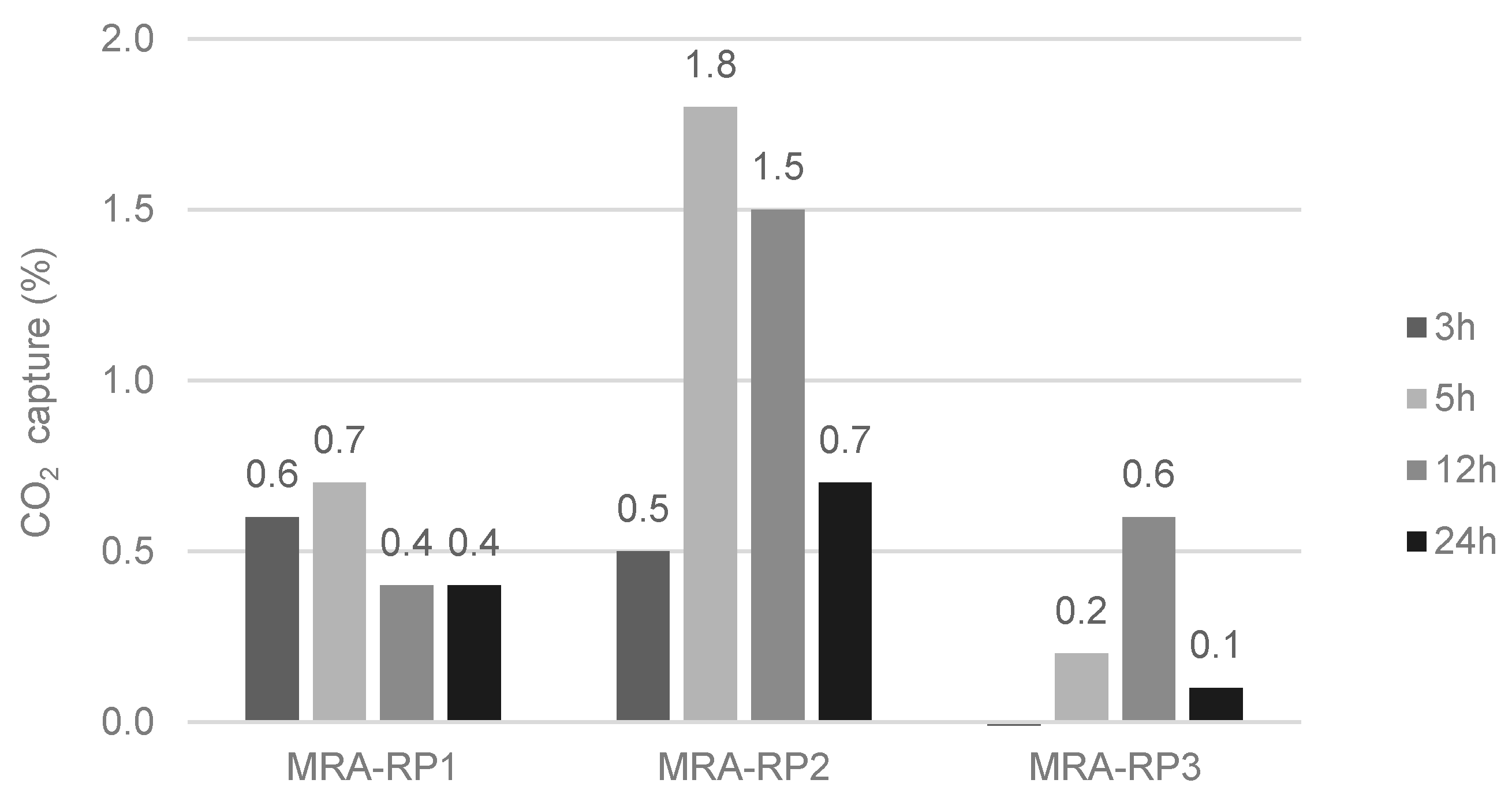
4.1. Mixed Recycled Aggregates

The XRD diffractograms of three mixed recycled aggregates collected directly in recycling plants (MRA-RP1, MRA-RP2 and MRA-RP3) are presented in Figure 1. The main minerals detected are quartz, muscovite, microcline, albite and calcite. No portlandite was detected under the detection limits of XRD analysis, which indicates a low carbonation potential of these MRAs.
MRA-RP1, MRA-RP2 and MRA-RP3 were subjected to forced carbonation for 3, 5, 12 and 24 h (Figure 2). MRA-RP1 and MRA-RP2 both registered the highest CO2 content at 5 h, while for MRA-RP3 the maximum CO2 content was reached at 12 h of carbonation. It was found that after the maximum CO2 was achieved, the CO2 uptake decreased. This phenomenon could be related to the acid attack, which promotes the dissolution of part of the calcium carbonate with CO2 liberation. In addition, it is well known that the formation of calcium carbonates at the surface restricts the diffusion of CO2 into the sample, which limits the CO2 absorption after the initial CO2 uptake. Fang et al. [68] also reported that the rate of CO2 uptake by RAs decreased with the carbonation time.
The CO2 uptake by MRA-RP1 was 0.7% after 5 h, which corresponds to 7.0 kg of CO2 captured per tonne of aggregate. A similar value was obtained for MRA-RP3 (0.6%) and slightly higher for MRA-RP2 (1.8%). Due to the insignificant amount of portlandite, it is likely that other calcium-hydrated products were carbonated. MRAs are composed of several materials, but only part of the Rc fraction contributes to carbonation (between 11 and 16% of Rc, which corresponds to the cement paste). Just considering the cement paste, MRA-RP1, MRA-RP2 and MRA-RP3 can capture, on average, 12.6%, 22.5% and 12.3% of CO2, respectively. This corresponds to 126 kg, 225 kg and 123 kg of CO2 per 1 tonne of cement paste presented in these aggregates, respectively.

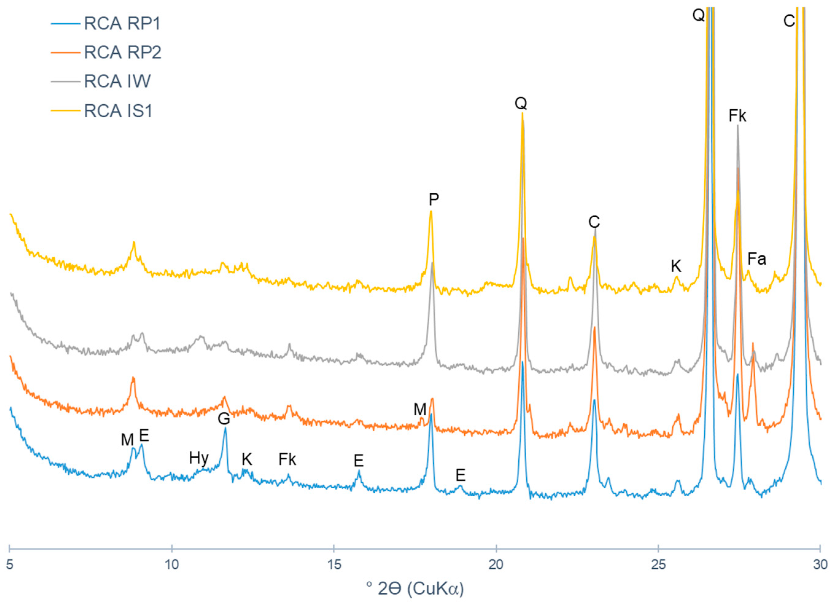
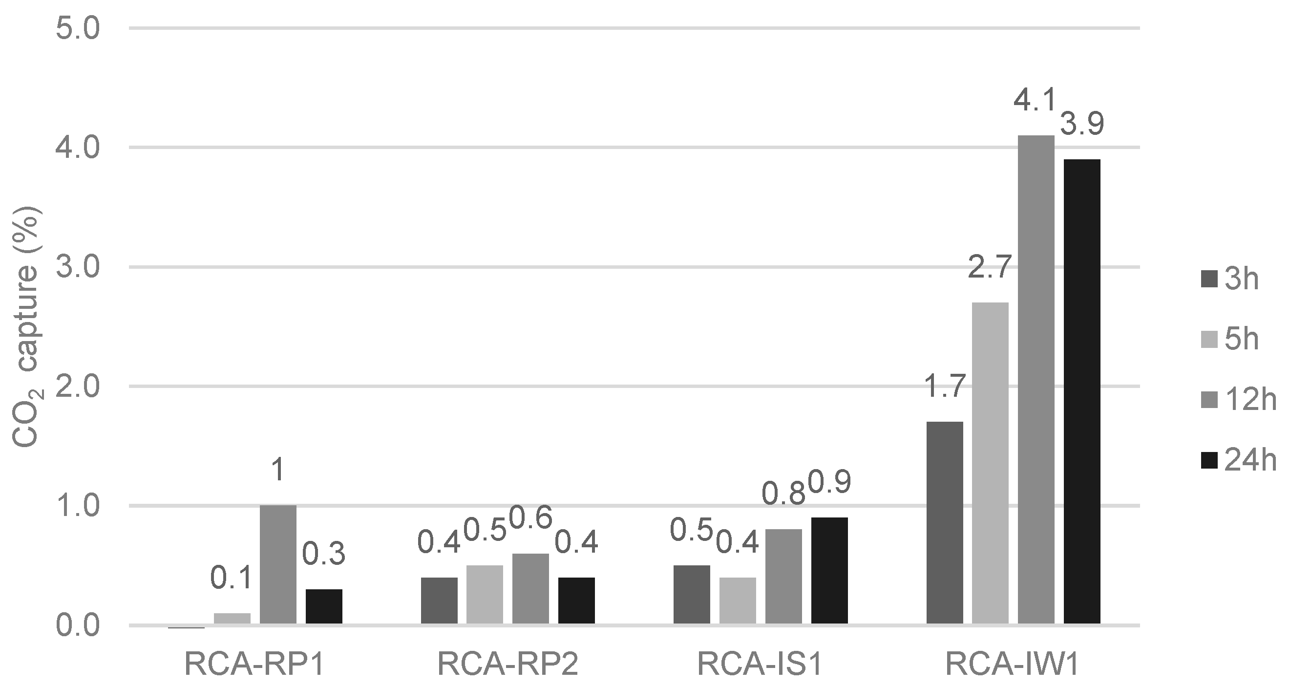
4.2. Recycled Concrete Aggregates from Recycling Plants

The XRD diffractograms of RCAs collected from recycling plants are presented in Figure 3. Due to the higher amount of cement fraction, the presence of portlandite is evident in these RCAs. The other main mineralogical compounds identified are calcite, quartz, microcline, ettringite, gypsum, muscovite, hydrocalumite, kaolinite and albite. In general, the RCA is mostly composed of calcite and quartz, as well as gypsum, sanidine and albite [69], which are not likely to carbonate. However, Garach et al. [70] found unhydrated cement remaining in RCAs and also MRAs, which are prone to carbonate. Another research [71] also characterized RCAs through XRD and verified that, besides the presence of carbonation products, such as calcite, aragonite and vaterite, unhydrated cement compounds, such as ettringite and calcium hydroxide, were not yet carbonated. Therefore, it shows that recycled aggregates contain compounds that can carbonate.
The evolution of the CO2 content of the RCAs at different carbonation periods (3 h, 5 h, 12 h, 24 h) is presented in Figure 4. It was observed that the maximum CO2 capture by RCAs occurred at 12 h of carbonation.
The maximum CO2 captured was 1.0%, 0.6%, 0.9% and 4.1%, for RCA-RP1, RCA-RP2, RCA-IS1 and RCA-IW1, respectively. The uptake of RCA-IW1 stands out from the other RCAs, indicating a higher carbonation potential, due to its higher cement content and not having been subject to previous natural carbonation.
As in MRAs, in RCAs, only part of the Rc fraction contributes to carbonation. Considering that Rc is 57.8%, 89.0%, 62.1% and 90.4% of RCA-RP1, RCA-RP2, RCA-IS1 and RCA-IW1, respectively, and taking into account that only 11%–16% of Rc contributes to carbonation, these aggregates can capture between 5.2% and 34.8% of CO2, per fraction of cement paste. This corresponds to an absorption between 52 kg and 348 kg of CO2 per tonne of cement paste.
Other studies also quantified the CO2 capture of RCAs. Kikuchi and Kuroda [72], reported that RCAs from recycling plants could capture approximately 11 kg of CO2 by 1 tonne of aggregate. In another study, RCAs from recycling plants showed a CO2 uptake capacity of 50 kg per tonne of aggregate [73]. Zhang et al. [33] state values of CO2 uptake up to 56% for smaller particles with larger specific surfaces. Such high values of CO2 uptake may be due to carrying out forced carbonation of RCAs under 100% of CO2. Xuan et al. [41] also quantified the CO2 uptake of RCAs from recycling plants. On average, the RCAs captured 5.2 kg of CO2 per tonne of aggregate.

4.3. Concrete Aggregate from Lab Specimens

To evaluate the maximum CO2 capture potential without previous carbonation, laboratory concrete samples (CA-L) were analysed. From XRD, CA-L contains portlandite and other major mineralogical compounds, namely gypsum, quartz, calcite and microcline (Figure 5).
The TG/DTG curves before carbonation and after 5 h of carbonation are presented in Figure 6. After 5 h of carbonation no mass loss due to portlandite decomposition is observed, with the corresponding increase in mass loss between 500 and 900 °C, attributed to the decarbonation of calcium carbonate.
The CA-L was able to capture 4.9% of CO2 per tonne of RA. As this aggregate contains 11% cement by weight, the cement paste captured 49 kg of CO2 captured per tonne of aggregate, which corresponds to 491.1 kg of CO2 per tonne of cement.
As expected, this sample was the one with the highest uptake of CO2, as it corresponds to a noncarbonated RCAs. It can be considered a reference recycled aggregate to evaluate the potential amount of CO2 that a common concrete can capture. However, this recycled aggregate is not common, unless it comes from concrete elements protected from the external environment.
Xuan et al. [41] also analysed the CO2 capture of laboratory-made CA. The authors concluded that CA sequestrated around 7.9 kg of CO2 by 1 tonne of aggregate.

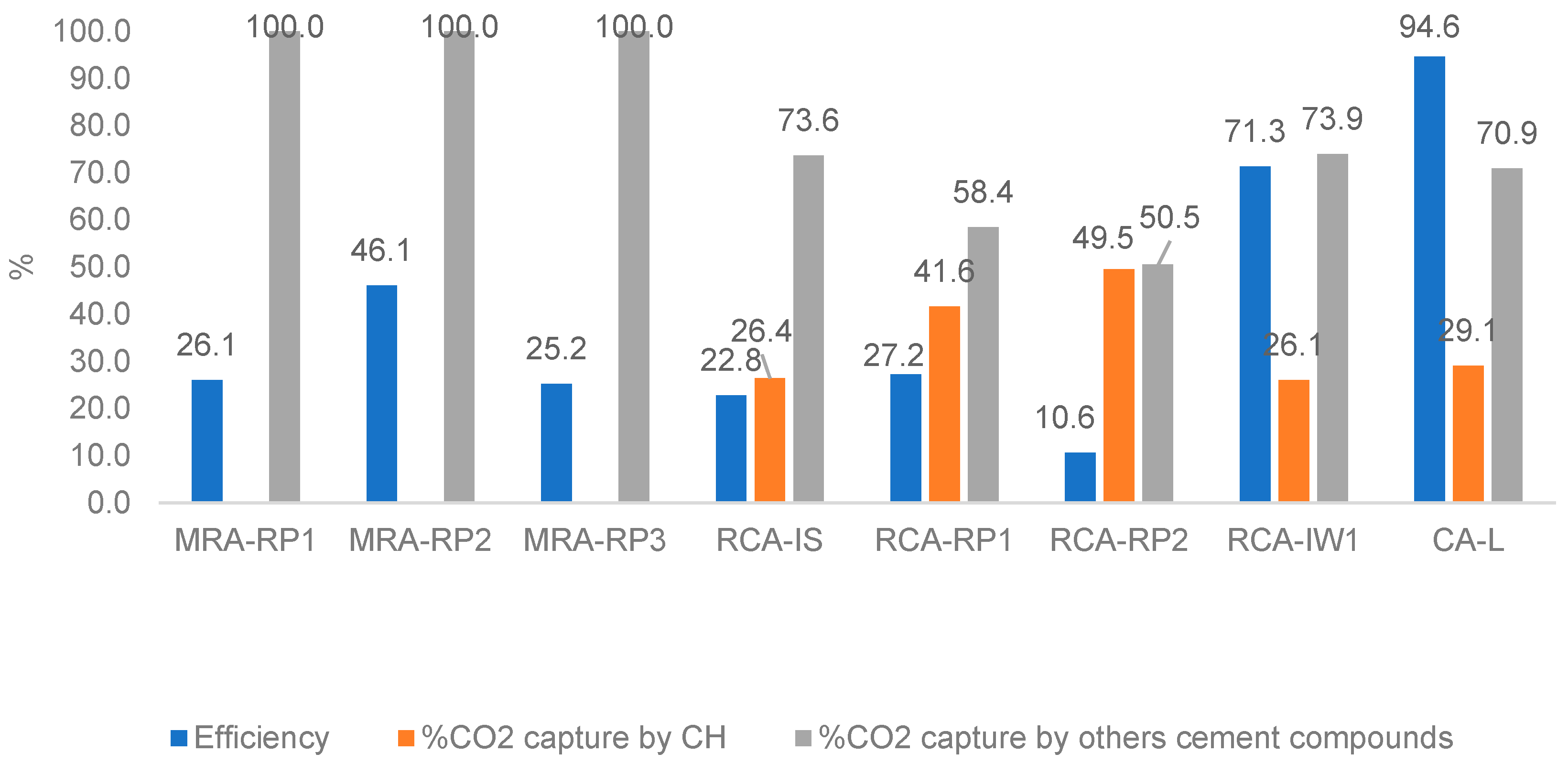
4.4. CO2 Uptake Efficiency of RAs and Calculation of Contribution of Cementitious Compounds for CO2 Capture

Figure 7 presents a summary of the CO2 uptake efficiency (Equation (7)) of each RA analysed in this study. The samples RCA-IW1 and CA-L differ from the remaining essentially because they are samples that had very low exposure to atmospheric CO2 and higher carbonation potential.
The CO2 uptake efficiency was calculated according to Equation (10). To obtain the maximum theoretical CO2 capture, it was assumed that all the cement paste presented in the aggregates is composed of CEM type I with, at least, 95% of Portland clinker. It was also considered that cement is composed of 60% CaO [74,75] and that all the calcium compounds present in the cement paste can react with CO2. Taking into account these assumptions, the maximum theoretical CO2 capture was calculated based on Rc values (Table 2) and considering an average value of 14% for the cement content in all RAs [76], with the exception of CA-L where its composition is known (11% cement). For example, for MRA-RP1, with 42.5% of Rc, the estimated CaO content is 3.5%, which corresponds, according to the stoichiometry, to a maximum theoretical CO2 capture of 2.8% (Equation (13)).
The maximum experimental CO2 capture was determined by TGA and corresponds to the maximum value obtained for each RA under forced carbonation conditions.
C O 2   u p t a k e   e f f i c i e n c y   o f   R A ( % ) = M a x i m u m   e x p e r i m e n t a l   C O 2   c a p t u r e M a x i m u m   t h e o r e t i c a l   C O 2   c a p t u r e × 100
M a x t h e o r e e t i c a l     C O 2   c a p t u r e = R c ( % ) × C e m e n t   c o n t e n t   ( % ) × % C a O   c e m e n t × M M C O 2 M M C a O
Figure 8 presents the values of efficiency obtained by forced carbonation and the respective contribution of remaining cement compounds in the RAs (portlandite and other cementitious compounds). The calculated efficiency value does not demonstrate the real susceptibility of the aggregate to carbonate, because the aggregates were already exposed to environmental conditions, but rather the efficiency of the method to achieve a totally carbonated aggregate.
The highest efficiency was obtained in the carbonation of CA-L and RCA-IW1, with 94.6% and 71.3%, respectively. These aggregates have the highest Rc fraction and are also the ones that had less exposure to the atmospheric environment (suffered less natural carbonation). It can be concluded that the reduction in carbonation efficiency is directly influenced by the cement content and the level of previous carbonation (during building the environment and after demolition).
Unlike MRAs, before carbonation RCAs present a significant portlandite content in their matrix, as well as other hydrated cementitious compounds (e.g., CSH and ettringite). The portlandite was totally consumed during the carbonation of RCA-RP1, RCA-RP2 and CA-L. In RCA-RP1 and RCA-RP2, about 42% and 50% of the produced CaCO3, respectively, was due to the carbonation of remaining portlandite. In this case, the CO2 uptake efficiency was 27.2% and 10.6%, respectively. RCA-IW1 and RCA-IS1 have a higher content of portlandite in their initial composition when compared with RCA-RP1 and RCA-RP2. In the case of RCA-IW1 there was a large decrease in portlandite content after carbonation, suggesting that it was completely consumed. The carbonation of portlandite was responsible for 26.1% of the CaCO3 content formed and the other 73.9% by carbonation of other hydrated cementitious compounds.
Based on the results obtained, and the test conditions employed, the carbonation of the RAs was mainly due to the hydrated calcium silicates and hydrated calcium aluminates of the cement.
The investigation of CO2 capture capacity of CDW was carried out in this paper for further application. It aims to use carbonated RAs in mortars and concrete as a substitute for natural aggregates. Note that aggregates represent a high proportion of mortars and concrete constituents, thus the replacement of natural aggregate by recycled aggregates means a high volume of RCA incorporation. Therefore, the percentage presented in this study is much higher if considered the incorporation proportion in mortars and concrete.
Additionally, an assessment of life cycle carbon impact was carried out. Mortars with carbonated recycled aggregates were compared with mortars with noncarbonated recycled aggregates and with reference mortars with natural aggregates.
The incorporation of recycled aggregates in mortars contribute to the reduction of CO2 when compared to the use of natural aggregates, depending on the type, origin and proposition of incorporation. Moreover, accelerated carbonation of recycled aggregates reduces even more the CO2 balance by capturing the CO2 emissions present.

5. Acid Attack of RAs during Forced Carbonation

Forced carbonation exposes recycled aggregates (RAs) to high concentrations of CO2, leading to the formation of carbonic acid within the pore sample. This carbonic acid can initiate an acid attack on the RA components, modifying the sample composition [77,78]. Calcium carbonate in natural environmental conditions (at constant pressure and temperature) is controlled primarily by the equilibrium reactions in Equations (2) and (14).
C a C O 3 + H 2 C O 3 C a 2 + + 2 H C O 3   ( Dissolution   of   calcium   carbonate )
Considering Equation (14), the equilibrium is shifted to the left with the increase in CO2 concentration (due to the continuous flow inside the chamber), favouring the formation of carbonic acid (H2CO3). The increase in H2CO3 will then cause a shift in the equilibrium of Equation (14) to the right, causing existent CaCO3 in the samples to dissolve. If the amount of CO2 is reduced in the system, the equilibrium in Equation (14) is then shifted to the left, promoting the precipitation of calcium carbonate. This proposed mechanism can justify the reduction of the calcium carbonate content after long periods of carbonation, as found in MRAs and RCAs.
This raised the question of whether an acid attack had occurred, promoting the partial dissolution of the calcium carbonate formed in the carbonation reaction and the consequent increase in pH of the RA interstitial solution. To validate this hypothesis, the pH was measured in three samples. The selected samples were MRA-RP1, which showed a reduction in CO2 content after 5 h of carbonation and RCA-IW1 and RCA-RP1, which showed the same behaviour, but after 12 h.
For MRA-RP1 the initial pH value (before carbonation, 0 h) was 9.5, decreasing to 9.1 after 5 h of carbonation (maximum capture of CO2). The decrease in the pH value is coherent with the increase in calcium carbonate content, meaning that more CO2 was captured by the RAs. After 12 h of carbonation, the pH value increased slightly from 9.1 to 9.2, which is consistent with an acid attack of CaCO3 and the consequent release of CO2.
The same behaviour was found in RCA-IW1 and RCA-RP1 at different carbonation ages: noncarbonated (0 h), at the age of highest CO2 capture (12 h) and after 24 h. Up to 12 h, the pH decreased, 12.6 to 12.1 and 11.5 to 10.5 (for RCA-IW1 and RCA-RP1, respectively), with the consequent increase in CO2 content from the formation of calcium carbonate. Then, the pH increased after 12 h as found in MRA-RP1, RCA-IW1 increased to 12.2 and RCA-RP1 to 10.8. This confirms the hypothesis of an acid attack, promoting the dissolution of part of the calcium carbonate with CO2 liberation.

6. Conclusions

Recycled aggregates from construction and demolition waste have been submitted to forced carbonation. Several types of RAs were investigated at different periods of carbonation. The quantification of CO2 uptake of RAs was carried out through thermogravimetric analysis. The following conclusions are drawn:
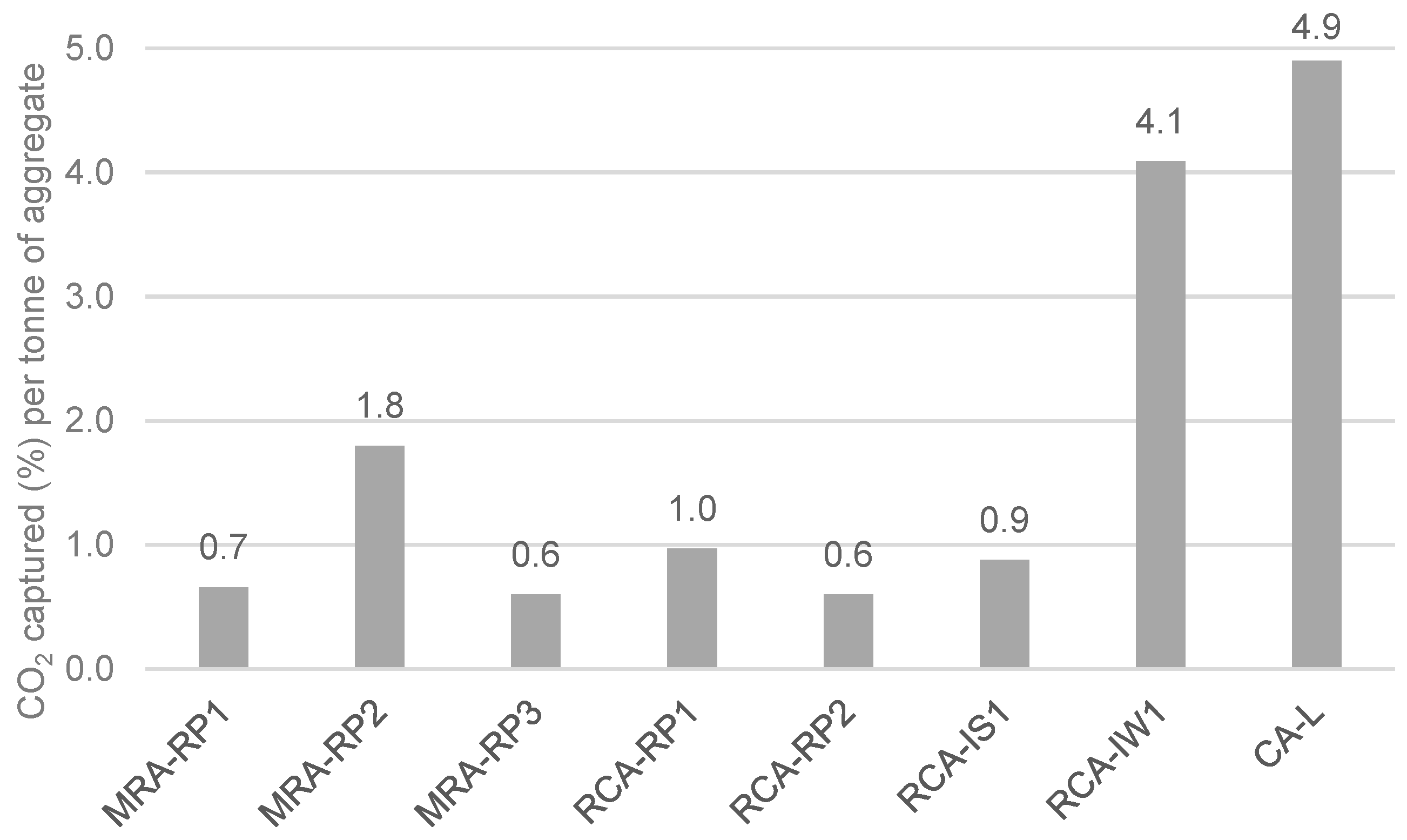
  • CO2 capture depends on the type of CDW (mixed or mainly concrete). Indeed, the maximum CO2 uptake is related to the cementitious materials content and to the degree of natural carbonation. In short, CDW captured from 5 wt.% to 35 wt.% of CO2 per tonne of cement paste, which corresponds to 0.6% to 4.1% per tonne of aggregate.
  • The lowest-captured CO2 value was 0.6% for MRA-RP3 and RCA-RP2 (corresponding to 6.0 kg per tonne of aggregate) and the highest was obtained in CA-L concrete produced in the laboratory with 4.9% (49 kg per tonne of aggregate). Considering that the MRAs did not present portlandite content, it was verified that the carbonation occurred by the reaction of CO2 and C-S-H.
  • Taking into account that only 13% to 16% of Rc fraction is composed of cement paste, forced carbonation allowed the aggregates to absorb between 20% and 27% of cement process emissions (the ones that refer to decarbonisation of calcium carbonate).
  • Forced carbonation does not continuously increase or stabilize over time. It reaches a maximum value of captured CO2 and then it goes down. After a given time, an acid attack occurs that reduces the calcium carbonate in the sample. The tested MRAs reached the maximum capture value after 5 h and the RCAs after 12 h.
  • It was also verified that long periods of exposure to CO2 do not contribute to the increase in CO2 capture by RAs. An acid attack occurs at longer carbonation periods. This attack promotes the dissolution of CaCO3, decreasing the potential for CO2 capture for long carbonation periods.
  • It was concluded that RAs, when submitted to forced carbonation, capture from 52 to 491 kg of CO2 per tonne of cement paste. Therefore, the forced carbonation of RAs, independently of the building life cycle (time and conditions of environmental exposure) and demolition carbonation phases, still has the potential to capture CO2.
  • The forced carbonation of recycled aggregates has a great influence on their characteristics. The characterization of the aggregates before and after their carbonation made it possible to analyse the modification in their physical properties, namely water absorption and particle density. During the carbonation, the precipitation of calcium carbonate inside the pores causes an increment in the density of the aggregate and decreases the water absorption. The physical properties are related to the carbonation potential of the aggregate.
Overall, this research highlights that recycled aggregates from construction and demolition wastes can be seen as sources of CO2 capture and storage. This contribution leads to the reduction of the carbon footprint of the cement industry and the more effective reuse of CDW.

Author Contributions

D.B.: Conceptualization, Investigation, Formal analysis, Writing—Original draft C.B.F.: Conceptualization, Supervision, Formal analysis, Writing- Reviewing and Editing C.M.P.: Supervision, Formal analysis, Writing—Reviewing and Editing R.V.: Supervision, Writing—Reviewing and Editing J.A.B.: Writing—Reviewing and Editing R.I.G.: Investigation A.S.S.: Supervision, Writing—Reviewing and Editing. All authors have read and agreed to the published version of the manuscript.

Funding

This research was funded within the research project AL7.1 by c5Lab (Interface Mission 01/C05-i02/2022.P264).

Institutional Review Board Statement

Not applicable.

Informed Consent Statement

Not applicable.

Data Availability Statement

Data is contained within the article.

Acknowledgments

The authors acknowledge for the financial support provided by the Interface Program, which plays a crucial role in sustaining the operations and research initiatives of c5Lab—Sustainable Construction Materials Association. The authors also acknowledge the National Laboratory for Civil Engineering (LNEC), and the research unit CERIS—Civil Engineering Research and Innovation for Sustainability (UIDB/04378/2020) for the support given to this research.

Conflicts of Interest

The authors declare no conflict of interest.

References

  1. Holban, E.; Deák, G.Y.; Daescu, V.; Diacu, E.; Daescu, A.I.; Tanase, G.S.; Marinescu, P.; Sirbu, C.; Paceagiu, J. Ways to reduce CO2 emissions and energetic consumption at clinker producing under Romanian specific conditions. J. Environ. Prot. Ecol. 2015, 16, 479–488. [Google Scholar]
  2. Nganga, G.; Alexander, M.; Beushausen, H. The design of concrete mixes with reduced clinker content. In Proceedings of the 34th Cement and Concrete Science Conference, Sheffield, UK, 14–16 September 2014. [Google Scholar]
  3. Imbabi, M.S.; Carrigan, C.; McKenna, S. Trends and developments in green cement and concrete technology. Int. J. Sustain. Built Environ. 2012, 1, 194–216. [Google Scholar] [CrossRef]
  4. Stanmore, B.R.; Gilot, P. Review-calcination and carbonation of limestone during thermal cycling for CO2 sequestration. Fuel Process. Technol. 2005, 86, 1707–1743. [Google Scholar] [CrossRef]
  5. Gomes, R.I.; Bastos, D.; Farinha, C.B.; Pederneiras, C.M.; Veiga, R.; de Brito, J.; Faria, P.; Silva, A.S. Mortars with cdw recycled aggregates submitted to high levels of CO2. Infrastructures 2021, 6, 159. [Google Scholar] [CrossRef]
  6. Zhang, N.; Duan, H.; Miller, T.R.; Tam, V.W.Y.; Liu, G.; Zuo, J. Mitigation of carbon dioxide by accelerated sequestration in concrete debris. Renew. Sustain. Energy Rev. 2020, 117, 109495. [Google Scholar] [CrossRef]
  7. Kashef-Haghighi, S.; Shao, Y.; Ghoshal, S. Mathematical modeling of CO2 uptake by concrete during accelerated carbonation curing. Cem. Concr. Res. 2015, 67, 1–10. [Google Scholar] [CrossRef]
  8. Peter, M.A.; Muntean, A.; Meier, S.A.; Böhm, M. Competition of several carbonation reactions in concrete: A parametric study. Cem. Concr. Res. 2008, 38, 1385–1393. [Google Scholar] [CrossRef]
  9. Thiery, M.; Villain, G.; Dangla, P.; Platret, G. Investigation of the carbonation front shape on cementitious materials: Effects of the chemical kinetics. Cem. Concr. Res. 2007, 37, 1047–1058. [Google Scholar] [CrossRef]
  10. Vogler, N.; Drabetzki, P.; Lindemann, M.; Kühne, H.C. Description of the concrete carbonation process with adjusted depth-resolved thermogravimetric analysis. J. Therm. Anal. Calorim. 2022, 147, 6167–6180. [Google Scholar] [CrossRef]
  11. Šavija, B.; Luković, M. Carbonation of cement paste: Understanding, challenges, and opportunities. Constr. Build. Mater. 2016, 117, 285–301. [Google Scholar] [CrossRef]
  12. Fernández-Carrasco, L.; Rius, J.; Miravitlles, C. Supercritical carbonation of calcium aluminate cement. Cem. Concr. Res. 2008, 38, 1033–1037. [Google Scholar] [CrossRef]
  13. Mitchell, M.J.; Jensen, O.E.; Cliffe, K.A.; Maroto-Valer, M.M. A model of carbon dioxide dissolution and mineral carbonation kinetics. Proc. R. Soc. A Math. Phys. Eng. Sci. 2010, 466, 1265–1290. [Google Scholar] [CrossRef]
  14. Fernández Bertos, M.; Simons, S.J.R.; Hills, C.D.; Carey, P.J. A review of accelerated carbonation technology in the treatment of cement-based materials and sequestration of CO2. J. Hazard. Mater. 2004, 112, 193–205. [Google Scholar] [CrossRef]
  15. Alapati, P.; Kurtis, K.E. Carbonation in Alternative Cementitious Materials: Implications on Durability and Mechanical Properties. In Proceedings of the International Conference on Durability of Concrete Structures, Leeds, UK, 18–20 July 2018; Volume 1. [Google Scholar]
  16. Pu, Y.; Li, L.; Wang, Q.; Shi, X.; Luan, C.; Zhang, G.; Fu, L.; El-Fatah Abomohra, A. Accelerated carbonation technology for enhanced treatment of recycled concrete aggregates: A state-of-the-art review. Constr. Build. Mater. 2021, 282, 122671. [Google Scholar] [CrossRef]
  17. Gholizadeh-Vayghan, A.; Bellinkx, A.; Snellings, R.; Vandoren, B.; Quaghebeur, M. The effects of carbonation conditions on the physical and microstructural properties of recycled concrete coarse aggregates. Constr. Build. Mater. 2020, 257, 119486. [Google Scholar] [CrossRef]
  18. Elsalamawy, M.; Mohamed, A.R.; Kamal, E.M. The role of relative humidity and cement type on carbonation resistance of concrete. Alexandria Eng. J. 2019, 58, 1257–1264. [Google Scholar] [CrossRef]
  19. Silva, R.V.; Neves, R.; De Brito, J.; Dhir, R.K. Carbonation behaviour of recycled aggregate concrete. Cem. Concr. Compos. 2015, 62, 22–32. [Google Scholar] [CrossRef]
  20. Liu, P.; Chen, Y.; Yu, Z. Effects of temperature, relative humidity and CO2 concentration on concrete carbonation. Mag. Concr. Res. 2020, 72, 936–947. [Google Scholar] [CrossRef]
  21. Shih, S.M.; Ho, C.S.; Song, Y.S.; Lin, J.P. Kinetics of the reaction of Ca(OH)2 with CO2 at low temperature. Ind. Eng. Chem. Res. 1999, 38, 1316–1322. [Google Scholar] [CrossRef]
  22. Leemann, A.; Moro, F. Carbonation of concrete: The role of CO2 concentration, relative humidity and CO2 buffer capacity. Mater. Struct. Constr. 2017, 50, 30. [Google Scholar] [CrossRef]
  23. Wang, D.; Noguchi, T.; Nozaki, T. Increasing efficiency of carbon dioxide sequestration through high temperature carbonation of cement-based materials. J. Clean. Prod. 2019, 238, 117980. [Google Scholar] [CrossRef]
  24. Fang, X.; Xuan, D.; Poon, C.S. Empirical modelling of CO2 uptake by recycled concrete aggregates under accelerated carbonation conditions. Mater. Struct. Constr. 2017, 50, 200. [Google Scholar] [CrossRef]
  25. Humbert, P.S.; Castro-Gomes, J.P.; Savastano, H. Clinker-free CO2 cured steel slag based binder: Optimal conditions and potential applications. Constr. Build. Mater. 2019, 210, 413–421. [Google Scholar] [CrossRef]
  26. Hyvert, N.; Sellier, A.; Duprat, F.; Rougeau, P.; Francisco, P. Dependency of C-S-H carbonation rate on CO2 pressure to explain transition from accelerated tests to natural carbonation. Cem. Concr. Res. 2010, 40, 1582–1589. [Google Scholar] [CrossRef]
  27. Ye, X.; Chen, T.; Chen, J. Carbonation of cement paste under different pressures. Constr. Build. Mater. 2023, 370, 130511. [Google Scholar] [CrossRef]
  28. Lyubomirskiy, N.; Bahtin, A.; Lyubomirskiy, N.; Bahtin, A. Temperature Influence on Forced Carbonation Speed of Half-Dry Pressure Lime Stone. Motrol. Motoryz. Energetyka Rol. 2015, 17, 73–80. [Google Scholar]
  29. Liska, M.; Al-Tabbaa, A. Performance of magnesia cements in pressed masonry units with natural aggregates: Production parameters optimisation. Constr. Build. Mater. 2008, 22, 1789–1797. [Google Scholar] [CrossRef]
  30. Vandeperre, L.J.; Al-Tabbaa, A. Accelerated carbonation of reactive MgO cements. Adv. Cem. Res. 2007, 19, 67–79. [Google Scholar] [CrossRef]
  31. Cui, H.; Tang, W.; Liu, W.; Dong, Z.; Xing, F. Experimental study on effects of CO2 concentrations on concrete carbonation and diffusion mechanisms. Constr. Build. Mater. 2015, 93, 522–527. [Google Scholar] [CrossRef]
  32. Castellote, M.; Fernandez, L.; Andrade, C.; Alonso, C. Chemical changes and phase analysis of OPC pastes carbonated at different CO2 concentrations. Mater. Struct. Constr. 2009, 42, 515–525. [Google Scholar] [CrossRef]
  33. Zhan, B.; Poon, C.S.; Liu, Q.; Kou, S.; Shi, C. Experimental study on CO2 curing for enhancement of recycled aggregate properties. Constr. Build. Mater. 2014, 67, 3–7. [Google Scholar] [CrossRef]
  34. Chen, M.; Wang, N.; Yu, J.; Yamaguchi, A. Effect of porosity on carbonation and hydration resistance of CaO materials. J. Eur. Ceram. Soc. 2007, 27, 1953–1959. [Google Scholar] [CrossRef]
  35. Zhao, Z.; Remond, S.; Damidot, D.; Courard, L.; Michel, F. Improving the properties of recycled concrete aggregates by accelerated carbonation. Proc. Inst. Civ. Eng. Constr. Mater. 2018, 171, 126–132. [Google Scholar] [CrossRef]
  36. Zhang, J.; Shi, C.; Li, Y.; Pan, X.; Poon, C.-S.; Xie, Z. Performance Enhancement of Recycled Concrete Aggregates through Carbonation. J. Mater. Civ. Eng. 2015, 27, 04015029. [Google Scholar] [CrossRef]
  37. Zhang, J.; Shi, C.; Li, Y.; Pan, X.; Poon, C.S.; Xie, Z. Influence of carbonated recycled concrete aggregate on properties of cement mortar. Constr. Build. Mater. 2015, 98, 1–7. [Google Scholar] [CrossRef]
  38. Nakarai, K.; Yoshida, T. Effect of carbonation on strength development of cement-treated Toyoura silica sand. Soils Found. 2015, 55, 857–865. [Google Scholar] [CrossRef]
  39. Tracz, T.; Zdeb, T. Effect of Hydration and Carbonation Progress on the Porosity and Permeability of Cement Pastes. Materials 2019, 12, 192. [Google Scholar] [CrossRef] [PubMed]
  40. Ikumapayi, C.M. Effects of Carbonation on the Properties of Concrete. Sci. Rev. 2019, 5, 205–214. [Google Scholar]
  41. Xuan, D.; Zhan, B.; Poon, C.S. Assessment of mechanical properties of concrete incorporating carbonated recycled concrete aggregates. Cem. Concr. Compos. 2016, 65, 67–74. [Google Scholar] [CrossRef]
  42. Lu, B.; Shi, C.; Cao, Z.; Guo, M.; Zheng, J. Effect of carbonated coarse recycled concrete aggregate on the properties and microstructure of recycled concrete. J. Clean. Prod. 2019, 233, 421–428. [Google Scholar] [CrossRef]
  43. Shi, C.; Li, Y.; Zhang, J.; Li, W.; Chong, L.; Xie, Z. Performance enhancement of recycled concrete aggregate—A review. J. Clean. Prod. 2016, 112, 466–472. [Google Scholar] [CrossRef]
  44. De Brito, J.; Agrela, F.; Silva, R.V. Construction and Demolition Waste; Elsevier Ltd.: Amsterdam, The Netherlands, 2018; ISBN 9780081024805. [Google Scholar]
  45. Rao, A.; Jha, K.N.; Misra, S. Use of aggregates from recycled construction and demolition waste in concrete. Resour. Conserv. Recycl. 2007, 50, 71–81. [Google Scholar] [CrossRef]
  46. Walton, J.C.; Bin-Shafique, S.; Smith, R.W.; Gutierrez, N.; Tarquin, A. Role of carbonation in transient leaching of cementitious wasteforms. Environ. Sci. Technol. 1997, 31, 2345–2349. [Google Scholar] [CrossRef]
  47. Lange, L.C.; Hills, C.D.; Poole, A.B. The effect of accelerated carbonation on the properties of cement- solidified waste forms. Waste Manag. 1996, 16, 757–763. [Google Scholar] [CrossRef]
  48. Tam, V.W.; Butera, A.; Le, K.N.; Li, W. CO2 concrete and its practical value utilising living lab methodologies. Clean. Eng. Technol. 2021, 3, 100131. [Google Scholar] [CrossRef]
  49. Le, H.B.; Bui, Q.B. Recycled aggregate concretes—A state-of-the-art from the microstructure to the structural performance. Constr. Build. Mater. 2020, 257, 119522. [Google Scholar] [CrossRef]
  50. Li, Y.; Fu, T.; Wang, R.; Li, Y. An assessment of microcracks in the interfacial transition zone of recycled concrete aggregates cured by CO2. Constr. Build. Mater. 2020, 236, 117543. [Google Scholar] [CrossRef]
  51. Li, Y.; Zhang, S.; Wang, R.; Zhao, Y.; Men, C. Effects of carbonation treatment on the crushing characteristics of recycled coarse aggregates. Constr. Build. Mater. 2019, 201, 408–420. [Google Scholar] [CrossRef]
  52. Russo, N.; Lollini, F. Effect of carbonated recycled coarse aggregates on the mechanical and durability properties of concrete. J. Build. Eng. 2022, 51, 104290. [Google Scholar] [CrossRef]
  53. Gomes, H.C.; Reis, E.D.; Azevedo, R.C.d.; Rodrigues, C.d.S.; Poggiali, F.S.J. Carbonation of Aggregates from Construction and Demolition Waste Applied to Concrete: A Review. Buildings 2023, 13, 1097. [Google Scholar] [CrossRef]
  54. EN 197-1; Cement Composition, Specifications and Conformity Criteria for Common Cements. British Standards Institution: London, UK, 2011.
  55. EN 933-11; Tests for Geometrical Properties of Aggregates. Part 11: Classification Test for the Constituents of Coarse Recycled Aggregate. British Standards Institution: London, UK, 2009.
  56. EN 13242; Aggregates for Unbound and Hydraulically Bound Materials for Use in Civil Engineering Work and Road Construction. British Standards Institution: London, UK, 2007.
  57. EN 1015-1; Methods of Test for Mortar for Masonry—Part 1: Determination of Particle Size Distribution (by Sieve Analysis). British Standards Institution: London, UK, 1998.
  58. Scrivener, K.; Snellings, R.; Lothenbach, B. A Practical Guide to Microstructural Analysis of Cementitious Materials, 1st ed.; CRC Press: Boca Raton, FL, USA, 2016. [Google Scholar]
  59. LNEC E 403; Análise Mineralógica por Difratometria de Raios X. LNEC: Lisbon, Portugal, 1993.
  60. Vaitkus, A.; Merkys, A.; Grazulis, S. Validation of the Crystallography Open Database using the Crystallographic Information Framework. J. Appl. Crystallogr. 2021, 54, 661–672. [Google Scholar] [CrossRef] [PubMed]
  61. Quirós, M.; Gražulis, S.; Girdzijauskaitė, S.; Merkys, A.; Vaitkus, A. Using SMILES strings for the description of chemical connectivity in the Crystallography Open Database. J. Cheminform. 2018, 10, 23. [Google Scholar] [CrossRef] [PubMed]
  62. Merkys, A.; Vaitkus, A.; Butkus, J.; Okulič-Kazarinas, M.; Kairys, V.; Gražulis, S. COD::CIF::Parser: An error-correcting CIF parser for the Perl language. J. Appl. Crystallogr. 2016, 49, 292–301. [Google Scholar] [CrossRef] [PubMed]
  63. Gražulis, S.; Merkys, A.; Vaitkus, A.; Okulič-Kazarinas, M. Computing stoichiometric molecular composition from crystal structures. J. Appl. Crystallogr. 2015, 48, 85–91. [Google Scholar] [CrossRef] [PubMed]
  64. Gražulis, S.; Daškevič, A.; Merkys, A.; Chateigner, D.; Lutterotti, L.; Quirós, M.; Serebryanaya, N.R.; Moeck, P.; Downs, R.T.; Le Bail, A. Crystallography Open Database (COD): An open-access collection of crystal structures and platform for world-wide collaboration. Nucleic Acids Res. 2012, 40, 420–427. [Google Scholar] [CrossRef]
  65. Graulis, S.; Chateigner, D.; Downs, R.T.; Yokochi, A.F.T.; Quirós, M.; Lutterotti, L.; Manakova, E.; Butkus, J.; Moeck, P.; Le Bail, A. Crystallography Open Database—An open-access collection of crystal structures. J. Appl. Crystallogr. 2009, 42, 726–729. [Google Scholar] [CrossRef]
  66. Downs, R.T.; Hall-Wallace, M. The American Mineralogist crystal structure database. Am. Mineral. 2003, 88, 247–250. [Google Scholar] [CrossRef] [PubMed]
  67. Wang, L.; Zhou, Y.; Shi, W. Random crowd-induced vibration in footbridge and adaptive control using semi-active TMD including crowd-structure interaction. Eng. Struct. 2024, 306, 117839. [Google Scholar] [CrossRef]
  68. Fang, X.; Zhan, B.; Poon, C.S. Enhancement of recycled aggregates and concrete by combined treatment of spraying Ca2+ rich wastewater and flow-through carbonation. Constr. Build. Mater. 2021, 277, 122202. [Google Scholar] [CrossRef]
  69. Saiz-Martínez, P.; Ferrández-Vega, D.; Morón-Fernández, C.; Payán De Tejada-Alonso, A. Comparative study of the influence of three types of fibre in the shrinkage of recycled mortar. Mater. Constr. 2018, 68, e168. [Google Scholar] [CrossRef]
  70. Garach, L.; López, M.; Agrela, F.; Ordóñez, J.; Alegre, J.; Moya, J.A. Improvement of bearing capacity in recycled aggregates suitable for use as unbound road sub-base. Materials 2015, 8, 8804–8816. [Google Scholar] [CrossRef] [PubMed]
  71. Bisciotti, A.; Jiang, D.; Song, Y.; Cruciani, G. Estimating attached mortar paste on the surface of recycled aggregates based on deep learning and mineralogical models. Clean. Mater. 2024, 11, 100215. [Google Scholar] [CrossRef]
  72. Kikuchi, T.; Kuroda, Y. Carbon dioxide uptake in demolished and crushed concrete. J. Adv. Concr. Technol. 2011, 9, 115–124. [Google Scholar] [CrossRef]
  73. Sereng, M.; Djerbi, A.; Metalssi, O.O.; Dangla, P.; Torrenti, J.M. Improvement of recycled aggregates properties by means of CO2 uptake. Appl. Sci. 2021, 11, 6571. [Google Scholar] [CrossRef]
  74. Mahdi, Z.H.; Abbas, W.A.; Abdulhussein, F.K.; Abdulghani, M.R.; Hasan, M.Q. Compressive strength and shrinkage of concrete containing calcium oxide (CaO) powder. IOP Conf. Ser. Mater. Sci. Eng. 2020, 881, 012165. [Google Scholar] [CrossRef]
  75. Shahzadi, P.; Shahnaz, A.; Khan, M.S.; Rana, B.B.; Chaudry, M.Y.; Yasmeen, S. A Short Study to Test the Compliance of Various Pakistani Ordinary Portland Cements with ASTM Composition Standards. Pakistan J. Chem. 2013, 3, 163–169. [Google Scholar] [CrossRef]
  76. Brazão Farinha, C.; Pederneiras, C.M.; Bastos, D.; Infante Gomes, R.; Veiga, R.; Santos Silva, A.; Martins, I. CDW as sources of CO2 absorption. In Proceedings of the V International Conference Progress of Recycling in the Built Environment, Weimar, Germany, 10–12 October 2023; pp. 227–234. [Google Scholar]
  77. Hadigheh, S.A.; Gravina, R.J.; Smith, S.T. Effect of acid attack on FRP-to-concrete bonded interfaces. Constr. Build. Mater. 2017, 152, 285–303. [Google Scholar] [CrossRef]
  78. Lokesh, K.; Reddy, M.; Kotaiah, B. Degradation of Concrete Structures and Protective Measures. Int. J. Eng. Res. Technol. (IJERT) 2014, 3, 1415–1420. [Google Scholar]
Figure 1. XRD pattern of noncarbonated MRA-RP1, MRA-RP2 and MRA-RP3. Notation: M—Muscovite; E—Ettringite; G—Gypsum; K—Kaolinite; Fk—Microcline; Fa—Albite; Q—Quartz; C—Calcite.
Applsci 14 05224 g001
Figure 2. Evolution of CO2 content in the samples MRA-RP1, MRA-RP2 and MRA-RP3 with increasing forced carbonation time.
Applsci 14 05224 g002
Figure 3. XRD pattern of uncarbonated RCAs: RCA-RP1, RCA-RP2, RCA-IS1 and RCA-IW1. Notation: M—Muscovite; E—Ettringite; Hy—Hydrocalumite; G—Gypsum; K—Kaolinite; Fk—Microcline; P—Portlandite; Q—Quartz; Fa—Albite; C—Calcite.
Applsci 14 05224 g003
Figure 4. Evolution of CO2 content in aggregates RCA-RP1, RCA-RP2, RCA-IS1 and RCA-IW1 with time of forced carbonation, determined from TGA.
Applsci 14 05224 g004
Figure 5. XRD pattern of uncarbonated CA-L. Notation: G—Gypsum; P—Portlandite; Q—Quartz; C—Calcite; Fk—Microcline.
Applsci 14 05224 g005
Figure 6. CA-L TGA before (0 h) and after 5 h of forced carbonation. Legend: 1—Dehydration of C-S-H; 2—Dehydroxilation of portlandite; 3—Decarbonation of amorphous calcium carbonate; 4—Decarbonation of crystallized calcium carbonate.
Applsci 14 05224 g006
Figure 7. Maximum amount of CO2 captured by the different RAs.
Applsci 14 05224 g007
Figure 8. Carbonation process efficiency and respective CO2 capture contribution.
Applsci 14 05224 g008
Table 1. Recycled aggregates studied.
Aggregate TypeDesignationOrigin (Collected at)Location
Mixed recycled aggregates (MRAs)MRA-RP1Recycling plant 1Pero Pinheiro, Portugal
MRA-RP2Recycling plant 2Figueira da Foz, Portugal
MRA-RP3Recycling plant 3Seixal, Portugal
Recycled concrete aggregates (RCAs)RCA-IW1Concrete producerAlhanda, Portugal
RCA-IS1Demolished in situ Setúbal, Portugal
RCA-RP1Recycling plant 1Pero Pinheiro, Portugal
RCA-RP2Recycling plant 4Bucelas, Portugal
Control concrete aggregates (CA)CA-LConcrete produced in laboratoryLisbon, Portugal
Table 2. RA classification.
WasteRc
(%)
Ru (%)Rb (%)Ra (%)Rg (%)X (%)Fl
(%)
Classification According to EN 933-11 [55] *
(as Per the Results Obtained in Laboratory)
MRA-RP142.527.521.79.60.20.8Fl5-Rc declared Rcug70 Rb30- Ra10- Rg2- X1- Fl5-
MRA-RP261.526.79.20.20.02.4Fl5-Rc50 Rg2- Rcug70 Rb10- Ra1- X1- Fl5-
MRA-RP337.416.326.66.26.96.7Fl5-Rc declared Rg2- Rcug70 Rb 30- Ra1- X1- Fl5-
RCA-IS62.118.018.40.00.10.5Fl5-Rc50 Rg2- Rcug70 Rb30- Ra1- X1- Fl5-
RCA-RP157.828.412.40.00.20.4Fl5-Rc50 Rg2- Rcug70 Rb30- Ra1- X1- Fl5-
RCA-RP289.010.60.40.00.00.0Fl5-Rc70 Rcug90 Rb10- Ra1- Rg2- X1- Fl5-
RCA-IW90.49.60.00.00.00.0Fl5-Rc90 Rcug90 Rb10- Ra1- Rg2- X1- Fl5-
CA-L90.79.30.00.00.00.0Fl5-Rc90 Rcug90 Rb10- Ra1- Rg2- X1- Fl5-
Note(s): * Classification of CDW-A constituents: concrete, concrete products, mortar and concrete masonry units (Rc); unbound aggregates, natural stone and hydraulically bound aggregates (Ru); clay masonry units (Rb); bituminous materials (Ra); glass (Rg); other materials, including cohesive, metals, plastic, rubber, non-floating wood and gypsum plaster (X); floating materials (F1).
Table 3. RA physical properties.
AggregateWater Absorption (%)Particle Density (kg/m³)
Non-CarbonatedCarbonatedNon-CarbonatedCarbonated
Natural sand0.25 ± 0.06-2627 ± 5-
MRA-RP17.05 ± 0.443.63 ± 0.232424 ± 662556 ± 48
MRA-RP2----
MRA-RP36.89 ± 0.913.90 ± 0.882485 ± 522570 ± 40
RCA-IS7.18 ± 0.204.87 ± 0.202426 ± 282640 ± 264
RCA-RP23.81 ± 0.542.45 ± 0.132636 ± 572694 ± 44
RCA-RP15.58 ± 1.182.48 ± 0.362510 ± 1302514 ± 12
RCA-IW5.01 ± 0.283.25 ± 0.342408 ± 18 2553 ± 5
CA-L4.74 ± 0.160.46 ± 0.042622 ± 72670 ± 9
Disclaimer/Publisher’s Note: The statements, opinions and data contained in all publications are solely those of the individual author(s) and contributor(s) and not of MDPI and/or the editor(s). MDPI and/or the editor(s) disclaim responsibility for any injury to people or property resulting from any ideas, methods, instructions or products referred to in the content.

