Article

The Impact of Inlet Structure on Stratification Performance in Thermal Storage Tanks: A Study through Simulation and Experimental Analysis

by
Yongjie Xing
1,
Xiaofen Zhang
2,
Zilong Zhang
2 and
Fang Liu
2,*
1
Institute of Resource and Environment, Beijing Academy of Science and Technology Senior Engineer, Beijing 100142, China
2
Beijing Key Laboratory of Heating, Gas Supply, Ventilating and Air Conditioning Engineering, Beijing University of Civil Engineering and Architecture, Beijing 100044, China
*
Author to whom correspondence should be addressed.
Appl. Sci. 2024, 14(12), 5248; https://doi.org/10.3390/app14125248
Submission received: 22 April 2024 / Revised: 12 June 2024 / Accepted: 13 June 2024 / Published: 17 June 2024
(This article belongs to the Special Issue Advanced Methodology and Analysis in Fire Protection Science)

Abstract

:

Featured Application

The elbow-type thermal storage tank is an innovative solution for thermal energy storage, with a uniquely designed bent pipe inlet structure that significantly increases hot water output and optimizes thermal stratification. This tank has demonstrated exceptional performance in reducing hot/cold water mixing and improving hot water availability. With its simple manufacturing process and easy installation, it not only meets users’ demands for an efficient hot water energy-saving application but is also in line with modern environmental and energy-saving concepts. The elbow-type storage tank has a wide range of applications in areas such as energy-efficient air conditioning and residential buildings, offering a new approach to energy use.

Abstract

Thermal storage tanks are the most widely used devices for thermodynamic storage. Their stratification performance is a key factor in determining their effectiveness. In this study, a structure was proposed to improve the thermal stratification of an elbow-type thermal storage tank. An experimental study was conducted on its exothermic properties for applications in hot water storage tanks. An experimental analysis was performed to investigate the exothermic properties of the proposed structure, and the results were compared with those obtained from simulations using CFD (ANSYS 19.1) software. To investigate the effect of thermal stratification on the water inlet structure, the Richardson number, hot water output rate, and MIX number of the elbow inlet structure were compared with those of the water distributor inlet structure. The results show that the MIX numbers corresponding to the inlet structures of the two types of tanks, the elbow and water distributor types, are not very different. These values were almost identical to the Richardson numbers. Under the same working conditions, the hot water output rate was 84.90% for the elbow inlet structure and 76.39% for the water distributor inlet structure. In conclusion, elbow-type water inlet structures are easy to install, and the manufacturing process is simplified.

1. Introduction

The continuous development of carbon peaking and carbon neutrality policies has attracted increasing attention to the issue of energy utilization, with energy storage recognized as an important and indispensable component in achieving these goals [1]. Currently, society is facing an “energy crisis”; therefore, the development and use of renewable resources are important for protecting the environment and sustaining a developing society [2,3,4]. Thermal storage is the most widely used form of energy storage, and the structural optimization of heat storage tanks has become a focal point for researchers.
Numerous studies have shown that an increase in water temperature leads to a decrease in water density. Inside the hot water tank, changes in buoyancy and gravity resulting from the varying densities of hot water cause the hot water to float. As the hot water rose to the upper part, the unboiled water sank to the lower part, creating stratification within the tank [5,6,7,8]. The layering effect in thermal storage tanks significantly affects operational efficiency, with well-stratified tanks meeting the heat load demand while improving energy use efficiency [9,10,11]. Parameters such as the Richardson number, MIX number, and hot water output rate have been proposed to describe tank stratification more intuitively [12].
The position and shape of the inlet and outlet, water flow rate, and internal structure of the water tank were factors that affected the temperature distribution inside the water tank. Eames and Norton et al. [13] showed that better thermal stratification in horizontal cylindrical storage tanks can be achieved by setting the inlets at different heights. Gao et al. [14] calculated the temperature and flow field distributions inside tanks using numerical simulations. They found that a central hole-type baffle plate could improve the temperature distribution in heat-storage tanks. Raines et al. [15] found that the stratification of a thermal storage tank improved when the inlet Froude number was less than 2. Wang [16] et al. studied the effect and mixing characteristics of thermal storage tanks under different conditions, finding a 10–15% efficiency improvement in stratified tanks over conventional tanks. Wang et al. [17] concluded that the optimum inlet flow rate of a thermal storage tank for achieving the best thermal stratification of the tank was 3 L/min. They also suggested that the inlet should be located at least two-thirds of the way up the tank. Hollands [18] and Berkel [19] performed experimental and numerical models of a thermal storage tank system by varying the inlet flow rate. They concluded that the thermal storage efficiency of the tank was high at low inlet velocities.
Among these factors, changing the shapes of the inlet and outlet is considered the most effective. Altering the design to reduce mixing between incoming and existing water flows makes it possible to minimize disturbances in temperature layering. Garnier et al. [20] modified the inlet and outlet pipes of a water tank to include multiple small diffusers and conducted simulations using CFD (ANSYS 19.1) software. The results indicate that a reasonable water distributor can reduce the mixing of hot and cold water and improve temperature stratification performance. Wang et al. [21] demonstrated that the inlet shape of a thermal storage tank significantly affects the thermal stratification within a phase change material tank. Through rigorous computational fluid dynamic (CFD) modeling, they concluded that the inlet structure was a crucial factor affecting the performance of thermal storage tanks. Moncho-Esteve et al. [22] utilized CFD tools to simulate the impact of various inlet devices on the thermal energy storage performance of storage tanks and the level of thermal stratification inside the tanks. This study found that sintered bronze conical diffusers outperformed elbow diffusers in terms of achieving better tank stratification. Bahnfleth et al. [23] introduced a slotted diffuser inlet method, which demonstrated that, at lower flow rates, there was less thickness in the slanting temperature layers with improved temperature stratification.
In previous studies, the inlet structure of the water tank [24] was studied for the water distributor type, ring type [23], radial disc type [25], equalizer type [26], and sharp-angled type [27]. In contrast, a curved inlet structure was not included in this study. This study proposes a new type of inlet/outlet structure called the elbow type, as shown in Figure 1. Figure 1a depicts the inlet shape, while Figure 1b illustrates the outlet shape. The fluid enters the system from the lower portion in the state of low-temperature cold water and exits from the upper portion in the state of high-temperature hot water. Water has small variations in pressure and flow rate. The inlet and outlet are located on the side of the heat storage tank, which has a simple structure and is relatively straightforward to process in comparison with other types of inlet and outlet structures. Neither domestic nor foreign researchers have investigated the thermal stratification of elbow-type inlet and outlet structures. Figure 1 shows that the elbow water inlet/outlet structure is easy to fabricate and can reduce damage to the inclined temperature layer in the water tank, resulting in better thermal stratification of the water tank. In terms of cost, the elbow-type inlet and outlet only require tube bending, whereas the distributor type requires more small holes in the inlet and outlet, resulting in a more complex structure. In subsequent operations, it is important to promptly determine the maintenance of water tanks with inlets and outlets. The water cloth type of the inlet and outlet has a complex structure, making cleaning difficult and increasing operating costs. Accordingly, an elbow-type inlet structure was investigated in this study.
In this study, a combination of numerical simulations and experiments was used to obtain the results of the thermal stratification of an elbow-type inlet structure. A comparison was made with a better thermally stratified water elbow-type inlet tank in the literature [28], and the exothermic performance of the tank was analyzed. A schematic of the water distributor-type inlet is shown in Figure 2.

2. Numerical Simulation Study of Thermal Storage Tanks
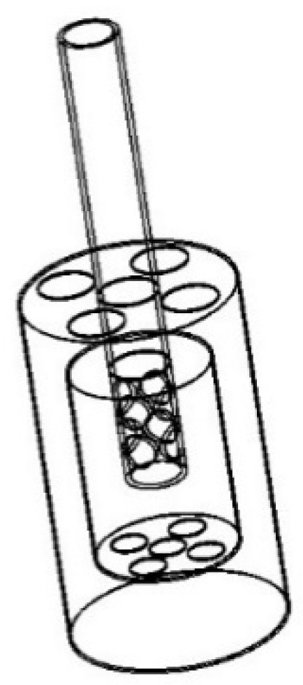
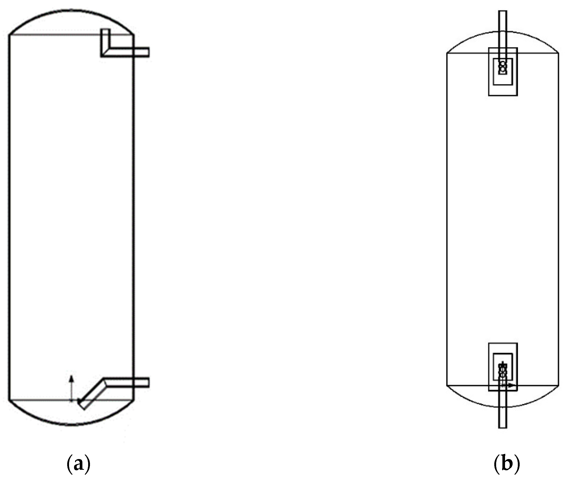
2.1. Physical Model

The use of the SOLIDWORKS v2018 software to establish a three-dimensional model of the water tank is illustrated in Figure 3. During the heat storage state, the water tank was positioned upwards, whereas during the exothermic state, it was positioned downwards. The inlet and outlet pipe diameters of the water tank were 23.2 mm and were imported into the CFD workbench, and the calculation domain was divided into unstructured grids. Grid-independence and time-step independence verification tests were conducted to ensure the accuracy of the calculation results. The model used in this study was tested with grid sizes ranging from 271,781 to 876,692 and time steps between 0.01 s and 0.1 s.

2.2. Mathematical Model

To ensure accurate calculations and simplify the process of analyzing the complex fluid flow and heat exchange during the experiment, the water tank numerical model was based on several assumptions.
The heat storage tank was adiabatic to the outside world. There is no heat exchange with the external environment.
The inlet structure walls were adiabatic, indicating that there was no heat transfer when water flowed from the inlet device into the tank.
The density and dynamic viscosity vary with temperature.
The continuity equation is as follows:
ρ t + ρ · V = 0
The momentum equation is as follows:
ρ u t + ρ u · u = p + · τ ρ β ( T T r e f ) g
The energy equation is as follows:
ρ c p T t + ρ c p u · T = · ( k T )
where ρ is the density of water, kg/m3; t is the time, s; V is the fluid partial velocity in the three directions of x, y, z, m/s; u is the fluid velocity, m/s; p is the pressure, Pa; β is the thermal expansion coefficient, 1/K; cp is the specific heat capacity of the constant pressure, J/(kg·K); k is the heat transfer coefficient of the fluid, W/(m2·K).

2.3. Boundary Conditions and Physical Properties

In this study, considering the effect of gravity, the energy equation and turbulence flow model were selected. The inlet of the tank was selected as the velocity inlet, the profile file was used to define the inlet temperature and velocity, and the outlet was selected as the free outflow. The convergence criterion requires residuals of less than 10−6 for the continuity equation, the momentum equation, and the energy equation and less than 10−3 for k and ε. The medium in the tank was water, and its density and dynamic viscosity varied with temperature. The density and dynamic viscosity values of water at each temperature were obtained using the physical and chemical manuals–Thermophysical Properties of Fluid Systems [29], and the data were taken every 5 °C in the range of 0–100 °C. The equations for the variation in the density and dynamic viscosity of water with temperature were fitted using Origin v2022 software. The density and dynamic viscosity as a function of time were assessed, and the functional relationship is shown in Equations (4) and (5).
Density with temperature change rule is as follows:
ρ = 0.00036 t 2 0.0764 t + 1000.7
The pattern of change of dynamic viscosity with temperature is as follows:
μ = 2.13 × 10 9 t 3 + 5.1 × 10 7 t + 0.02 t 2

3. Experimental Study

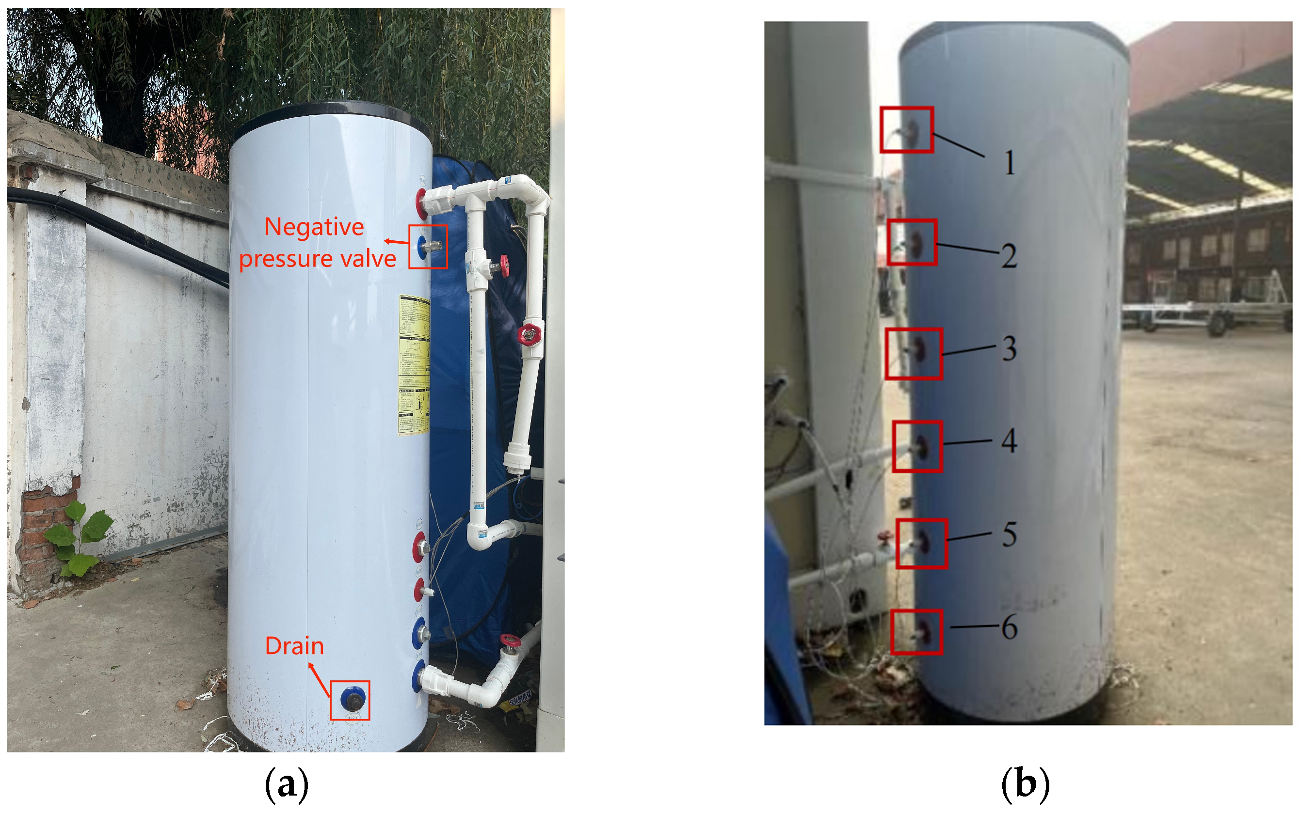
3.1. Experimental Test Platform System

An experimental test platform (a test platform for the stratification characteristics of a hot water storage tank) was set up, consisting mainly of flow meters, temperature sensors, a water pump, a heat storage tank, a heat pump, and a shut-off valve. A schematic of this process is shown in Figure 4. The model numbers and parameters of the equipment used in the experimental setup are presented in Table 1 and Table 2, respectively.
The system includes a heat storage tank, heat pump, circulation pump, shut-off valve, and various pipes (G3, G2, G4, G5) that connect these components. When the heat storage, heat pump, circulation pump, and shut-off valve were opened, tap water flowed through pipe G3 into the heat storage tank, through pipe G2 into the heat pump for heating, and finally through pipe G4 into the hot water tank. Water was then released through pipe G5. It is important to note that during this process, heat storage occurred faster than exothermic release. Once the temperature probe in water tank 6 reaches 45 °C or higher, the heat storage process ends. When the heat was released, the heat pump, circulation pump, and shut-off valve were closed. Tap water enters the lower part of the hot water tank through G3, and high-temperature water is discharged through G5. The inlet water timing started when the inlet water temperature was equal to the outlet water temperature and ended when the temperature and flow were recorded.

3.2. Experimental Process

During the experimental process, tap water was introduced into the system for both heat storage and heat release operations. Throughout the heat storage phase, hot water flowed into the upper portion of the storage tank, whereas cold water entered the lower section. After the heat pump was deactivated, stratification occurred in the water stored in the tank. Slight changes were observed in both the tap water pressure and tank inlet velocity during the heat release phase. In addition, the inlet water temperature underwent temporal variations owing to fluctuations in the outdoor temperature.
The thermal storage tank was designed according to the manufacturer’s specifications, with specific parameters for its internal lining: a diameter (D) of 42 cm and height (H) of 142 cm, giving a height-to-diameter ratio between 3 and 4, which was optimized to maintain excellent stratification [30,31,32]. It had a capacity of 200 L, and the water inlet was positioned 20 cm from the bottom. In addition, the outlet was 20 cm from the top, utilizing bent-pipe configurations for both the entry and exit. A physical drawing of the tank is shown in Figure 5, and a schematic of the internal structure is shown in the physical model below, which is also equipped with a drain and negative pressure valve. To ensure continuous observation of the tank layering phenomenon, six temperature measurement points, labeled points 1 through 6 in descending order from the top to the bottom of the tank, were set up. The measurement points are counted from top to bottom as points 1–6. These points were connected to a control cabinet, which displayed the temperature of each measurement point to monitor the stratification of the water in the tank. A diagram of the flow meter and temperature sensor is shown in Figure 6.

3.3. Theory of Energy Calculation

3.3.1. Richardson Number

According to Hahne et al. [33], the Richardson number (Ri) can be used to qualitatively describe the temperature stratification in a tank, which indicates the importance of natural convection in forced convection. The thermal stratification effect is commonly employed to characterize tank stratification. Specifically, a higher Richardson number indicates more effective stratification within the water storage [34,35]. To quantify this effect, the Richardson number was calculated using Equation (6).
R i = G r R e 2 = g β H 3 ( T t o p T b o t t o m ) v 2 ( u i n H v ) 2 = g β H ( T t o p T b o t t o m ) u i n 2
where Gr is the Grashof number; Re is the Reynolds number; g is the acceleration of gravity, m/s2; T t o p , T b o t t o m is the temperature at the top of the tank and the temperature at the bottom of the tank, °C; H is the height of the tank, m; β is the thermal expansion coefficient, 1/K; υ is the kinematic viscosity, m2/s; u i n is the inlet velocity, m/s.

3.3.2. Hot Water Output Rates

The concept of hot water output rate, originally introduced by Afshin and Lavan [36,37], serves as a metric for quantitatively comparing tank performance in the scientific literature. This metric, which is expressed as the ratio of the volume of hot water discharged from the tank to its total volume over a defined period [38], depends on the stratification characteristics of the tank. Given its significance in assessing the performance of thermal storage systems, Equation (7) can be employed to calculate the hot water output rate for scientific investigations.
η e x t = Q t V
where Q is the inlet flow rate, m3/s; t* is the time spent when the temperature difference between the inlet and outlet water decreases by 10% from the initial temperature difference value. Moreover, 10% is a more subjective value [38], s; V is the tank volume, m3.

3.3.3. MIX Number

Anderson et al. [39] introduced the MIX number, which is a widely used metric for characterizing the stratification effect in tanks. This parameter quantifies the thermal stratification within the tank at a particular instant, ranging from zero to one, indicating different degrees of thermal stratification. In an ideal scenario where hot and cold water are perfectly stratified within the tank, the MIX number approaches zero. Conversely, when hot and cold water within the tank was fully mixed, the MIX number attained a value of 1. A reduction in this value indicates an improvement in stratification associated with a reduction in the thermocline thickness within the stratified layers [40,41]. To calculate the MIX number, the tank was conceptually divided into N horizontally arranged layers, each with an equal volume (V). The energy contained within each tank layer is designated as E, whereas the momentum of this energy is defined as M. Equation (8) provides a mathematical framework for computing the MIX number, drawing upon these fundamental concepts [28].
M I X   n u m b e r = M s t r M e x p M s t r M f u l l m i x e d
M e x p = i = 1 n y i E i
E i = ρ · V i · C p · T i
where M s t r is the momentum of energy when the tank is perfectly stratified, kg·m/s; M e x p is the momentum of energy when the tank is experimented with, kg·m/s; M m i x is the momentum of energy when the tank is completely mixed, kg·m/s. y i is the distance from the center of each water layer to the bottom of the tank (m), and Ei is the energy of each part of the water (J).
E s t r = E e x p
where
E s t r = ρ · C p · V h o t · T h o t + ρ · C p · V c o l d · T c o l d
V t o t a l = V h o t + V c o l d
The position of the oblique temperature layer, y s t r , is determined by Equation (14).
V c o l d = y s t r · π · D 2 4
Based on V h o t and V c o l d , the momentum of the ideal stratified water tank was determined using Equation (15).
M s t r = i = 1 n y i · E s t r
where
E f u l l y m i x e d = ρ · V i · C p · T f u l l y m i x e d
M f u l l y m i x e d = i = 1 n y i E f u l l y m i x e d
This approach offers a scientifically rigorous means of assessing tank stratification, enabling researchers to quantify the performance of thermal storage systems and identify areas for optimization.

3.3.4. Error Analysis

To verify the accuracy of the CFD verification model, the temperature variation with time at each measurement point during the experimental and simulation periods was calculated. The simulated temperatures were compared with the measured experimental temperatures using a Root Mean Square Error (RMSE) model. The RMSE is defined in (18) as follows:
R M S E = i = 0 n ( e i m i ) 2 / N
where e i is the experimental measurement, m i is the simulated measurement, and N is the experimental time.

4. Results and Discussion

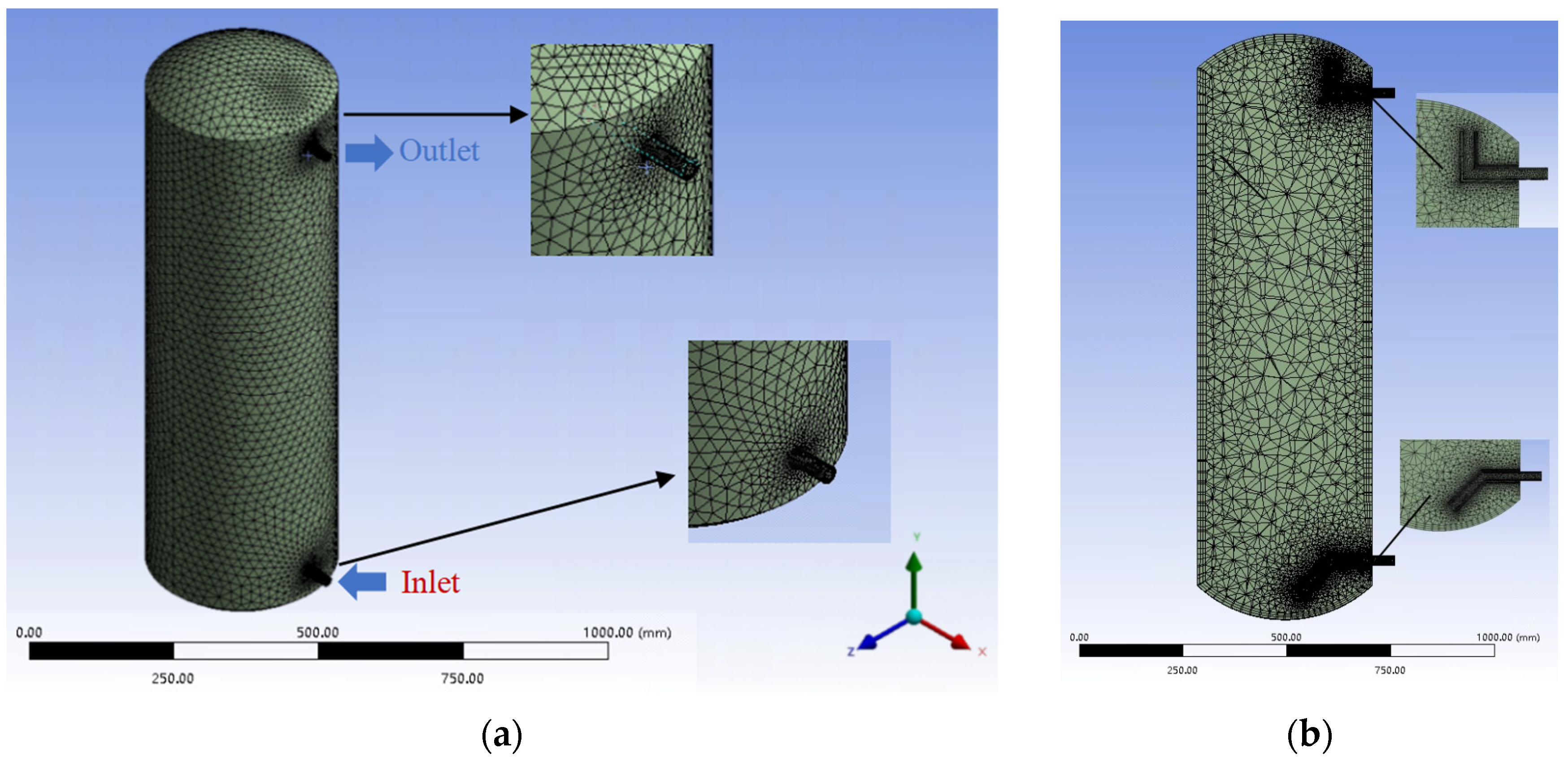
4.1. Grid Independence Verification

The selection of an appropriate meshing level is crucial for accurate and efficient thermal simulation. In this study, three distinct meshing levels were carefully evaluated, with the number of meshes being 271,781 (level 1), 452,629 (level 2), and 876,692 (level 3), respectively. The meshing diagram of the water tank in Figure 7 shows a tetrahedral grid structure and topical encryption. To verify the grid independence of the model, a reference point located 200 mm from the bottom of the tank section was chosen, and its temperature variations over nondimensional time were analyzed. As shown in Figure 8, the temperature curves obtained from the three meshing levels exhibit remarkable consistency, indicating that the choice of grid count minimally impacts the temperature calculation results. Given the need to optimize computational efficiency without compromising accuracy, a model with 271,781 grids was chosen for this study. This selection ensures accurate simulations while minimizing computational time, thereby facilitating efficient and reliable thermal engineering analyses.

4.2. Time Step Independence Verification

When calculating transient states, it is crucial to set the time step appropriately because the accuracy of the simulation results depends on it. In this study, time steps of 0.01 s, 0.05 s, and 0.1 s were used to investigate the effect of different time steps on the convergence of the calculation results. Figure 9 shows the change in temperature for non-dimensional time. Notably, the temperature recorded with a time step of 0.05 s deviated by 0.30% and 0.09% from that obtained with 0.01 s and 0.1 s, respectively. Balancing the need for computational efficiency with the requirement for accuracy, we opted to utilize a time step of 0.05 s for our simulations. This choice ensured that our results were both accurate and computationally efficient, enabling us to conduct reliable transient-state simulations.

4.3. Simulation and Experimental Results Analysis

The experimental and simulated temperature profiles were compared, and the data were found to be consistent, thus verifying the authenticity of the simulation. In the existing literature [34], it has been reported that distributor-type water inlet structures exhibit superior stratification characteristics in water tanks. In this study, we aimed to compare and analyze the experimental outcomes with the simulation results for both elbow and water distributor-type tanks. This study investigated the temperature distributions of two types of tank inlet and outlet structures at t = 200 s, 700 s, 1200 s, and 1700 s to provide a comprehensive visualization of the thermal behavior within the tanks. The cloud diagrams of the temperature distributions at different times for different types of thermal storage tanks are presented in Figure 10 and Figure 11. As shown in Figure 10b and Figure 11b, the temperature stratification effect of the two types was more obvious and consistent at t = 700 s.

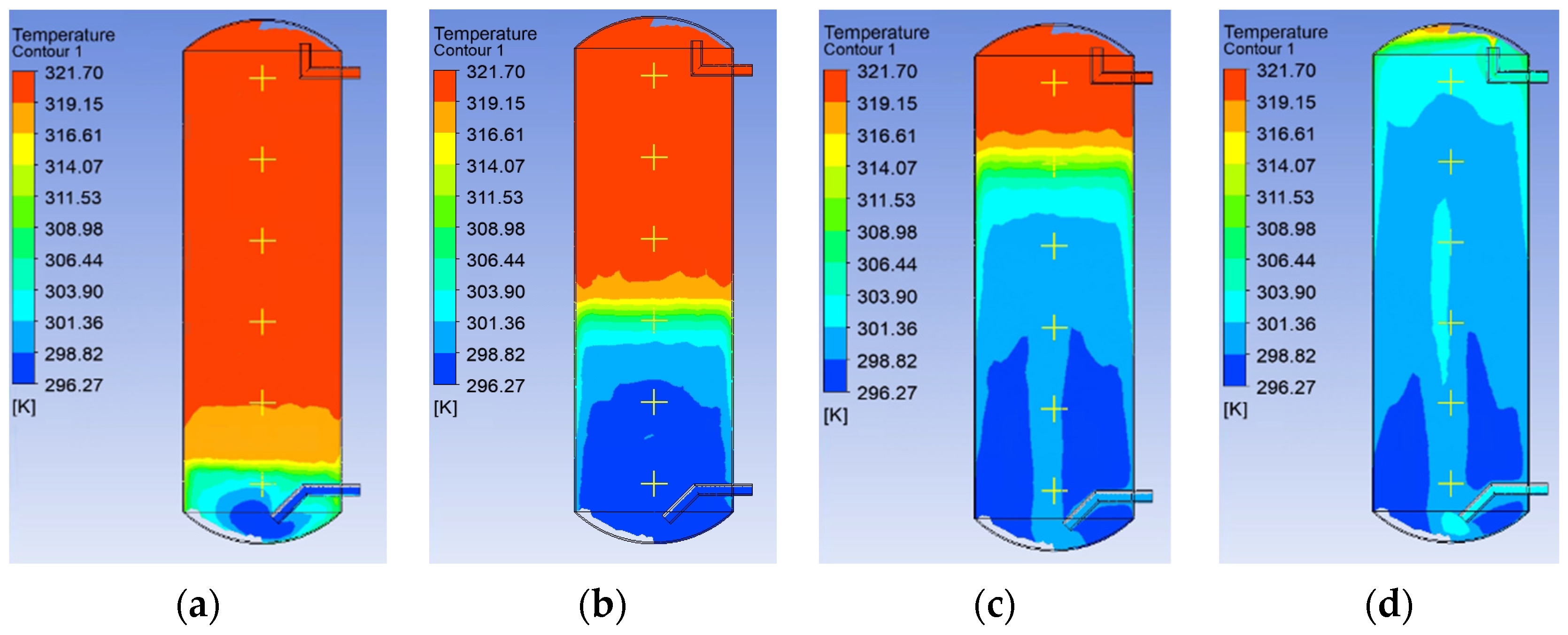
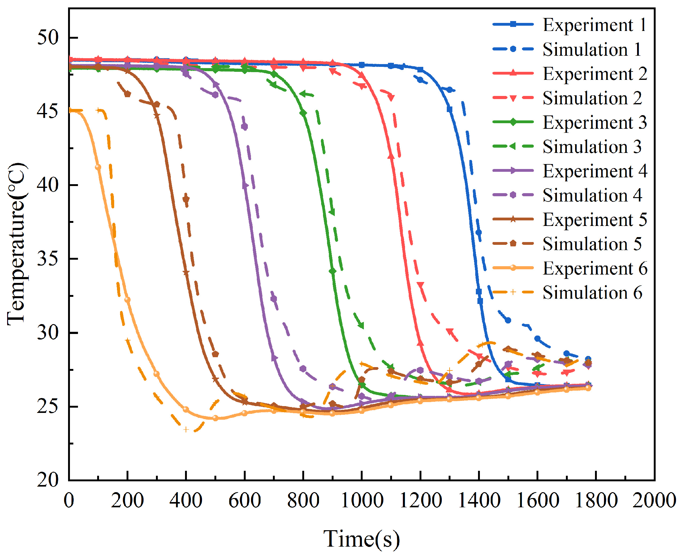
4.3.1. Analysis of Temperature Profiles

To ensure the precision of both the experimental and simulated data for the heat-storage tank with a bending inlet structure, six distinct measurement points were selected. A rigorous comparative analysis of the temperature change curves across various time intervals demonstrated the concordance between the experimental observations and simulation outcomes. This alignment not only validates the precision of our experimental setup but also attests to the accuracy of our simulation model, indicating the accuracy of the simulation and experiment. The temperature curves at each measurement point are shown in Figure 12. Figure 12 shows the temperature curves captured at each measurement point, further corroborating the reliability of our findings.
Figure 13 shows the temperature profiles recorded at each measurement point in the simulation of the water distributor- and elbow-type inlet temperature profiles. Under the initial conditions, the energy in the water tank remained constant. The exothermic conditions, comparison of different structures, the same measurement point, and the tank inlet were in constant contact with cold water, which ensured that the lower measurement point temperature remained consistent. According to the conservation of energy and specific heat capacity formula, a structure with a higher temperature at the measurement point results in better temperature stratification of the tank.
As shown in Figure 13, at 1500 s, the temperature at measurement point 1 of the water distributor inlet was 28.2 °C, while the temperature at measurement point 1 of the curved tube inlet was 34.59 °C. The temperatures at measurement point 6 were identical for all the structures. Given identical inlet conditions and all other initial parameters being equal, it is evident that the elbow-type inlet exhibits superior temperature stratification compared with the water distributor-type inlet.

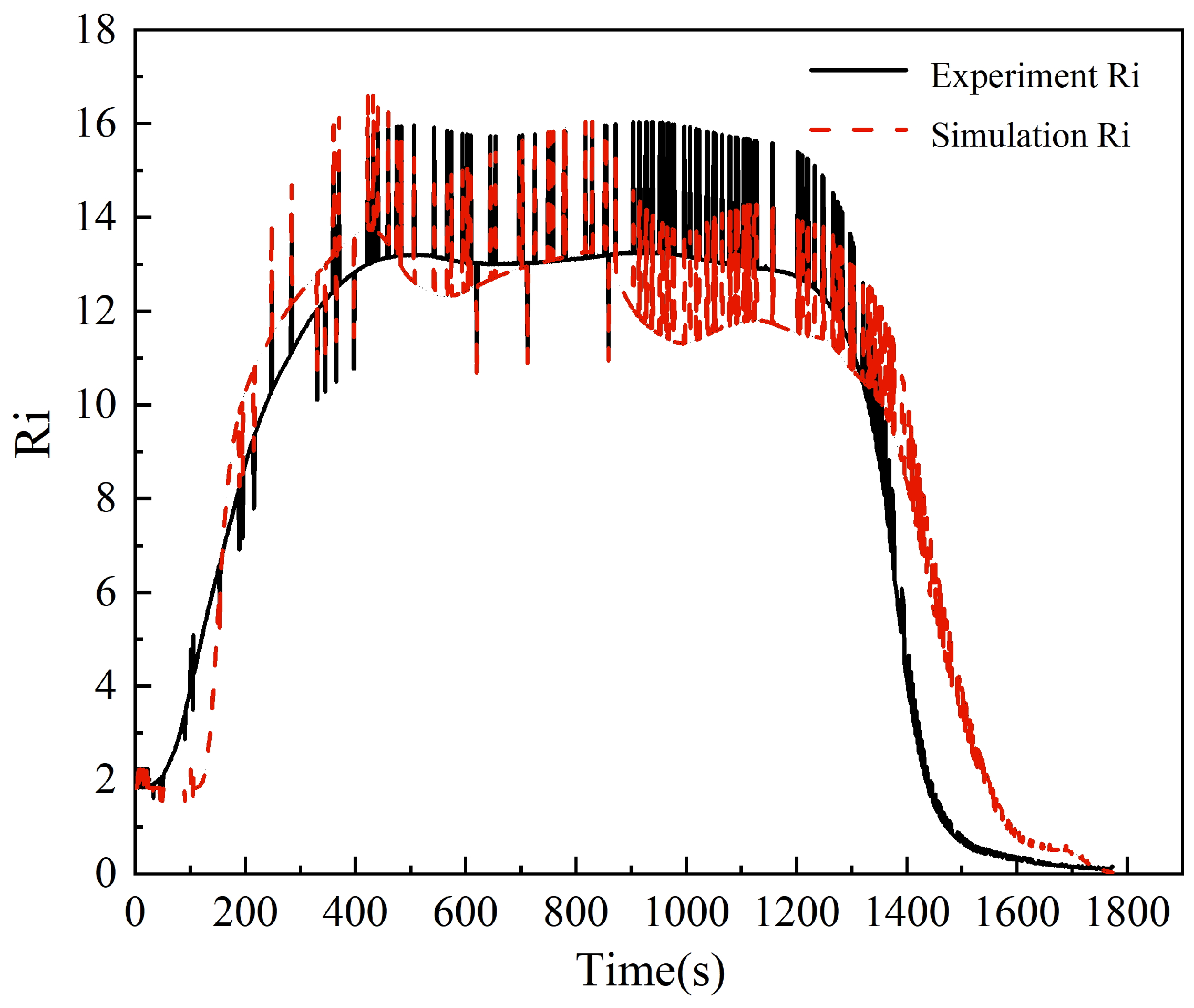
4.3.2. Analysis of Richardson Number

The Richardson number indicates how well the stratification effect performs with the mixing effect. It is the ratio of the levitation effect to the mixing effect.
The experimental and simulated Ri values for the heat-storage water tank utilizing an elbow-type inlet structure aligned closely, as shown in Figure 14. The data indicated an initial growth pattern, followed by a subsequent decline. The main reason for this trend is that the temperature of the water remains constant in the beginning, and as the hot and cold water flow in and out, they cause changes in the buoyancy and mixing forces. However, the temperature distribution within the water tank became more stratified. This stratification is influenced by buoyancy force, which causes warmer water to rise and colder water to sink. Additionally, mixing forces, such as the turbulence generated by water flow, also play a role in determining the temperature distribution. Towards the end of the experiment and simulation, the Richardson number decreased. This decrease can be attributed to the fact that the water temperature in the tank stabilizes around 26 °C, resulting in reduced differences in temperature and, consequently, smaller changes in buoyancy and mixing forces. During the experiment, the maximum Richardson number reached 16.03, whereas in the simulation, it peaked at 16.61, at which time the stratification in the tank was the best. When the Richardson number was high, the buoyancy forces dominated, leading to better temperature stratification within the tank. In this case, the peak values of the Richardson number occurred when the tank was approximately half-filled with hot water and an equivalent amount of cold water was introduced. Under these conditions, hot water occupies the upper part of the tank, whereas cold water settles at the bottom. This temperature stratification led to increased buoyancy forces and, consequently, an increase in the Richardson number. The close agreement between the experimental and simulated data validated the accuracy of the simulation model.
A comparison of the simulation results for the elbow- and water-distributor-type inlets is shown in Figure 15. The maximum Richardson number by calculation for the water distributor-type inlet is 16.9, while for the elbow-type inlet, it is 16.3. It is evident that the Richardson numbers for both inlet types are nearly identical, indicating a similarity in their fluid dynamic behaviors. When the flow rate remained constant, the water entering through the elbow-type inlet directly impacted the top of the tank and did not disturb its layered structure. Conversely, the water distributor-type inlet regulates the flow rate into the tank by dispersing water through small holes in the wall. Upon passing through the distributor, water flows within the tank primarily because of buoyancy.
This comparative analysis provides a comparison of the performance characteristics of different inlet types, which can inform the design and optimization of tank systems for various applications.

4.3.3. Analysis of Hot Water Output Rates

During the experiment, the flow rate was maintained at 441.18 L/h, which corresponded to a velocity of 0.29 m/s. The initial temperature difference was set at 18.66 °C, and it took 1470 seconds for the temperature to drop to 10% of its initial value. Notably, the tank achieved a hot water output rate of 88.42%. The temperature difference between the inlet and outlet showed an initial increase, followed by a decrease during the exothermic period. During the simulation, the simulation results show that the initial temperature difference of the elbow-type inlet is 19.1 °C, and it takes 1412 s to drop to 10%. The hot water output rate of the tank was 84.9%. Comparatively, the water distributor-type inlet had an initial temperature difference of 16.28 °C. The time to reach a 10% temperature drop was 1272 s, and the tank’s hot water output rate was 76.39%. The hot water output rate of the elbow-type inlet structure was improved by 8.51% compared to the water distributor-type inlet structure.
In a previous study [42], a hot water output rate of 74.98% was reported at an inlet flow rate of 253.82 L/h. Although they are consistent with our simulation results, it is evident that the elbow-type inlet and outlet configurations exhibit higher hot water output rates than the water distributor type. This enhancement suggests improved efficiency in the energy utilization of the system.

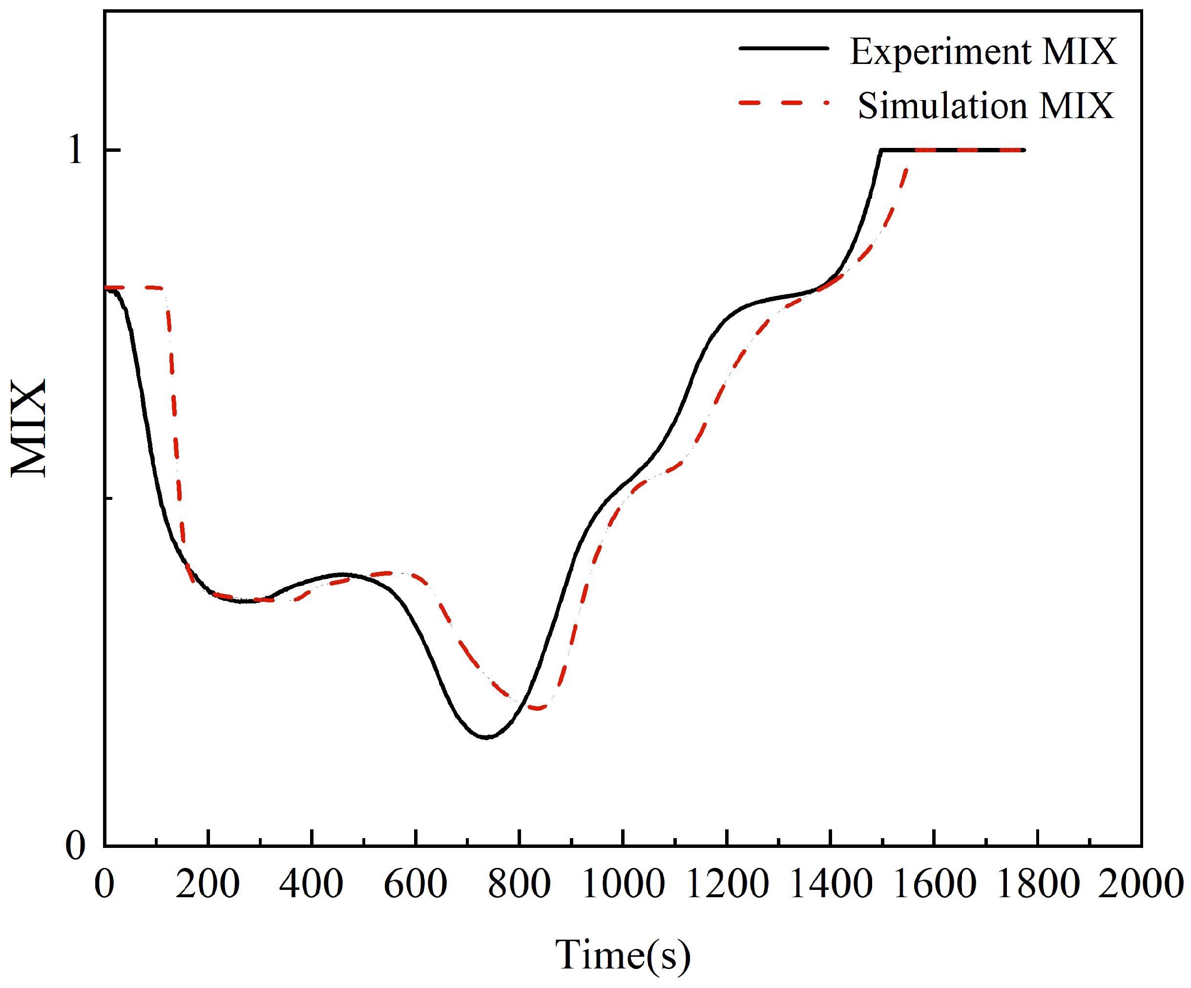
4.3.4. Analysis of MIX Number

The MIX number reflects the degree of mixing between cold and hot water in thermal storage tanks from an energy perspective and provides a more accurate description of their stratification.
As shown in Figure 16, the elbow-type inlet structure of the heat storage tank, with the change in the time MIX number, tended to first decrease and then increase. The experiment demonstrated that the stratification effect of the water tank varied over time. This shows that the water tank stratification effect changes from poor to good and then to poor with time. At the outset of the experiment, the water temperature hovered around 46 °C, resulting in a relatively poor stratification effect. As the tank discharged hot water through its outlet and cold water entered the inlet, the stratification gradually improved, resulting in a higher hot water output rate. However, as the quantity of cold water in the tank increased and the amount of hot water decreased, the MIX number reached its minimum value. This indicates that the tank has a better hot water output rate. In the experiment, this occurred at 737 s, where the minimum value was 0.1549; in the simulation, this occurred at 835 s, where the minimum value was 0.1976. The stratification effect was best at this time, and then the MIX number slowly increased. Subsequently, the MIX number began to rise slowly, indicating a gradual decline in the stratification quality.
A simulated comparison of the MIX number between the distributor inlet and elbow inlet is shown in Figure 17, which shows that the minimum value of the MIX number of the water distributor inlet occurred at 773 s, with a minimum value of 0.2048. There is little difference between the MIX numbers of the elbow-type and water distributor inlets, indicating that the layering effect during the exothermic heat release of the elbow-type and water distributor inlets is comparable to that of their inlets. Notably, there was no significant difference in the MIX numbers between the two inlet types.

5. Conclusions

In this study, a type of elbow intake structure was proposed, and a mathematical model was established to compare and analyze the experimental data with the simulated data and the simulated data of different intake structures. The temperature profiles, Richardson number, hot water output rate, and MIX number, which characterize the performance characteristics of thermal stratification, were used for comparative analysis. The conclusions are as follows:
The mathematical model proposed in this study showed a high degree of agreement between experimental data and simulation results, with a deviation of less than 10%. This confirms the accuracy and reliability of the model.
In the simulation results of the elbow type and water distributor type inlets, the maximum value of the Richardson number of the water distributor-type inlets was 16.9, the maximum value of the elbow type was 16.3, the minimum value of MIX number of the water distributor-type inlets was 0.1976, and the minimum value of MIX number of the elbow type was 0.2048. The deviation of the Richardson number of the two structures and the MIX number is not large, which can be seen as the elbow type and the water distributor type of the water into the tank will not destroy the original stratification structure of the tank; thus, the tank has better thermal stratification performance characteristics.
The hot water output rate of the elbow-type inlet was 84.9%, and the hot water output rate of the water distributor-type inlet was 76.39%. Compared with the water distributor-type inlet, the elbow-type inlet achieved an 8.51% increase in hot water output rate. This translates into providing more hot water to users in practical applications, resulting in the improved operational efficiency of the system.
The design of the elbow-type inlet minimized disturbances within the tank, enabling the preservation of the original thermal stratification structure of the tank, thereby enhancing its thermal stratification performance.
In particular, the elbow-type inlet structure minimizes the disturbances within the tank, allows for natural stratification, and enhances the hot water output rate, thereby effectively optimizing the stratification performance of the tank. This innovative design holds promise for practical applications and enhances overall system efficiency.

Author Contributions

Conceptualization, Y.X. and F.L.; methodology, Y.X.; software, X.Z.; validation, Y.X., F.L. and Z.Z.; formal analysis, X.Z.; investigation, Y.X.; resources, F.L.; data curation, X.Z.; writing—original draft preparation, Y.X.; writing—review and editing, X.Z.; visualization, Y.X.; supervision, F.L.; project administration, Z.Z. All authors have read and agreed to the published version of the manuscript.

Funding

This study received no external funding.

Institutional Review Board Statement

Not applicable.

Informed Consent Statement

Not applicable.

Data Availability Statement

The data presented in this study are available on request from the corresponding author due to privacy.

Conflicts of Interest

The authors declare no conflicts of interest.

References

  1. Liu, Z.; Sun, T.; Yu, Y.; Ke, P.; Deng, Z.; Lu, C.; Huo, D.; Ding, X. Near-Real-Time Carbon Emission Accounting Technology Toward Carbon Neutrality. Engineering 2022, 14, 44–51. [Google Scholar] [CrossRef]
  2. Panwar, N.L.; Kaushik, S.C.; Kothari, S. Role of Renewable Energy Sources in Environmental Protection: A Review. Renew. Sustain. Energy Rev. 2011, 15, 1513–1524. [Google Scholar] [CrossRef]
  3. Kothari, R.; Tyagi, V.V.; Pathak, A. Waste-to-Energy: A Way from Renewable Energy Sources to Sustainable Development. Renew. Sustain. Energy Rev. 2010, 14, 3164–3170. [Google Scholar] [CrossRef]
  4. Pietrosemoli, L.; Rodriguez-Monroy, C. The Venezuelan Energy Crisis: Renewable Energies in the Transition towards Sustainability. Renew. Sust. Energ. Rev. 2019, 105, 415–426. [Google Scholar] [CrossRef]
  5. García-Marí, E.; Gasque, M.; Gutiérrez-Colomer, R.P.; Ibáñez, F.; González-Altozano, P. A New Inlet Device That Enhances Thermal Stratification during Charging in a Hot Water Storage Tank. Appl. Therm. Eng. 2013, 61, 663–669. [Google Scholar] [CrossRef]
  6. Haller, M.Y.; Cruickshank, C.A.; Streicher, W.; Harrison, S.J.; Andersen, E.; Furbo, S. Methods to Determine Stratification Efficiency of Thermal Energy Storage Processes—Review and Theoretical Comparison. Sol. Energy 2009, 83, 1847–1860. [Google Scholar] [CrossRef]
  7. Erdemir, D.; Altuntop, N. Improved Thermal Stratification with Obstacles Placed inside the Vertical Mantled Hot Water Tanks. Appl. Therm. Eng. 2016, 100, 20–29. [Google Scholar] [CrossRef]
  8. Njoku, H.O.; Ekechukwu, O.V.; Onyegegbu, S.O. Analysis of Stratified Thermal Storage Systems: An Overview. Heat Mass Transf. 2014, 50, 1017–1030. [Google Scholar] [CrossRef]
  9. Chandra, Y.P.; Matuska, T. Stratification Analysis of Domestic Hot Water Storage Tanks: A Comprehensive Review. Energy Build. 2019, 187, 110–131. [Google Scholar] [CrossRef]
  10. Lima, J.B.A.; Prado, R.T.A.; Montoro Taborianski, V. Optimization of Tank and Flat-Plate Collector of Solar Water Heating System for Single-Family Households to Assure Economic Efficiency through the TRNSYS Program. Renew. Energy 2006, 31, 1581–1595. [Google Scholar] [CrossRef]
  11. Shafieian, A.; Bahrami, H.-R.; Roostaee, A.; Feyzi, S.S. Effects of Different Inlet Configurations on the Performance of Solar Storage Tanks: A Three-Dimensional Unsteady CFD Simulation. Case Stud. Therm. Eng. 2023, 45, 103019. [Google Scholar] [CrossRef]
  12. Castell, A.; Medrano, M.; Solé, C.; Cabeza, L.F. Dimensionless Numbers Used to Characterize Stratification in Water Tanks for Discharging at Low Flow Rates. Renew. Energy 2010, 35, 2192–2199. [Google Scholar] [CrossRef]
  13. Eames, P.C.; Norton, B. The Effect of Tank Geometry on Thermally Stratified Sensible Heat Storage Subject to Low Reynolds Number Flows. Int. J. Heat Mass Transf. 1998, 41, 2131–2142. [Google Scholar] [CrossRef]
  14. Gao, L.; Lu, H.; Sun, B.; Che, D.; Dong, L. Numerical and Experimental Investigation on Thermal Stratification Characteristics Affected by the Baffle Plate in Thermal Storage Tank. J. Energy Storage 2021, 34, 102117. [Google Scholar] [CrossRef]
  15. Baines, W.D.; Martin, W.W.; Smith, D.M. Development of Stratification in a Rectangular Tank by Horizontal Inflow. J. Fluids Eng. 1983, 105, 59–64. [Google Scholar] [CrossRef]
  16. Wang, D.; Liu, H.; Wang, Y.; Liu, K.; Liu, Y.; Gao, M.; Fan, J. Thermal Performance and Evaluation of a Novel Stratified and Mixed Flexible Transformation Solar Heat Storage Unit. Build. Simul. 2023, 16, 1881–1895. [Google Scholar] [CrossRef]
  17. Wang, Z.; Zhang, H.; Dou, B.; Huang, H.; Wu, W.; Wang, Z. Experimental and Numerical Research of Thermal Stratification with a Novel Inlet in a Dynamic Hot Water Storage Tank. Renew. Energy 2017, 111, 353–371. [Google Scholar] [CrossRef]
  18. Hollands, K.G.T.; Lightstone, M.F. A Review of Low-Flow, Stratified-Tank Solar Water Heating Systems. Sol. Energy 1989, 43, 97–105. [Google Scholar] [CrossRef]
  19. Van Berkel, J. Mixing in Thermally Stratified Energy Stores. Sol. Energy 1996, 58, 203–211. [Google Scholar] [CrossRef]
  20. Garnier, C.; Muneer, T.; Currie, J. Numerical and Empirical Evaluation of a Novel Building Integrated Collector Storage Solar Water Heater. Renew. Energy 2018, 126, 281–295. [Google Scholar] [CrossRef]
  21. Wang, Z.; Zhang, H.; Dou, B.; Zhang, G.; Wu, W. Influence of Inlet Structure on Thermal Stratification in a Heat Storage Tank with PCMs: CFD and Experimental Study. Appl. Therm. Eng. 2019, 162, 114151. [Google Scholar] [CrossRef]
  22. Moncho-Esteve, I.J.; Gasque, M.; González-Altozano, P.; Palau-Salvador, G. Simple Inlet Devices and Their Influence on Thermal Stratification in a Hot Water Storage Tank. Energy Build. 2017, 150, 625–638. [Google Scholar] [CrossRef]
  23. Bahnfleth, W.P.; Song, J. Constant Flow Rate Charging Characteristics of a Full-Scale Stratified Chilled Water Storage Tank with Double-Ring Slotted Pipe Diffusers. Appl. Therm. Eng. 2005, 25, 3067–3082. [Google Scholar] [CrossRef]
  24. Yaïci, W.; Ghorab, M.; Entchev, E.; Hayden, S. Three-Dimensional Unsteady CFD Simulations of a Thermal Storage Tank Performance for Optimum Design. Appl. Therm. Eng. 2013, 60, 152–163. [Google Scholar] [CrossRef]
  25. Chung, J.D.; Cho, S.H.; Tae, C.S.; Yoo, H. The Effect of Diffuser Configuration on Thermal Stratification in a Rectangular Storage Tank. Renew. Energy 2008, 33, 2236–2245. [Google Scholar] [CrossRef]
  26. Qin, Y.; Wang, Z.; Zhang, H.; Dou, B.; Zhang, G.; Wu, W.; Wu, C. The Effect of Phase Change Material Balls on the Thermal Characteristics in Hot Water Tanks: CFD Research. Appl. Therm. Eng. 2020, 178, 115557. [Google Scholar] [CrossRef]
  27. Yang, Z.; Chen, H.; Wang, L.; Sheng, Y.; Wang, Y. Comparative Study of the Influences of Different Water Tank Shapes on Thermal Energy Storage Capacity and Thermal Stratification. Renew. Energy 2016, 85, 31–44. [Google Scholar] [CrossRef]
  28. Wu, F.; Wang, Z.; Zhang, H.; Qin, Y.; You, X.; Lu, J. Experimental and Simulation Analysis on Thermal Stratification Characteristics in Solar Storage Tanks with Phase Change Materials. J. Energy Storage 2022, 46, 103722. [Google Scholar] [CrossRef]
  29. Thermophysical Properties of Fluid Systems. Available online: https://webbook.nist.gov/chemistry/fluid/ (accessed on 26 March 2024).
  30. Fernández-Seara, J.; Uhı’a, F.J.; Sieres, J. Experimental Analysis of a Domestic Electric Hot Water Storage Tank. Part II: Dynamic Mode of Operation. Appl. Therm. Eng. 2007, 27, 137–144. [Google Scholar] [CrossRef]
  31. Kenjo, L.; Inard, C.; Caccavelli, D. Experimental and Numerical Study of Thermal Stratification in a Mantle Tank of a Solar Domestic Hot Water System. Appl. Therm. Eng. 2007, 27, 1986–1995. [Google Scholar] [CrossRef]
  32. Hariharan, K.; Badrinarayana, K.; Srinivasa Murthy, S.; Krishna Murthy, M.V. Temperature Stratification in Hot-Water Storage Tanks. Energy 1991, 16, 977–982. [Google Scholar] [CrossRef]
  33. Hahne, E.; Chen, Y. Numerical Study of Flow and Heat Transfer Characteristics in Hot Water Stores. Sol. Energy 1998, 64, 9–18. [Google Scholar] [CrossRef]
  34. Zurigat, Y.H.; Liche, P.R.; Ghajar, A.J. Influence of Inlet Geometry on Mixing in Thermocline Thermal Energy Storage. Int. J. Heat Mass Transf. 1991, 34, 115–125. [Google Scholar] [CrossRef]
  35. Gerhardt, F.L.C.; Salvo, R.d.V.; de Marchi Neto, I.; de Lima, R.S.; Silva, R.C. da Computational Modeling of a Thermal Energy Storage Tank Coupled to a Water-Cooled Household Refrigerator. J. Energy Storage 2021, 41, 102961. [Google Scholar] [CrossRef]
  36. Lavan, Z.; Thompson, J. Experimental Study of Thermally Stratified Hot Water Storage Tanks. Sol. Energy 1977, 19, 519–524. [Google Scholar] [CrossRef]
  37. Ghajar, A.J.; Zurigat, Y.H. Numerical Study of the Effect of Inlet Geometry on Stratification in Thermal Energy Storage. Numer. Heat Transf. Part A Appl. 1991, 19, 65–83. [Google Scholar] [CrossRef]
  38. Hegazy, A.A. Effect of Inlet Design on the Performance of Storage-Type Domestic Electrical Water Heaters. Appl. Energy 2007, 84, 1338–1355. [Google Scholar] [CrossRef]
  39. Andersen, E.; Furbo, S.; Fan, J. Multilayer Fabric Stratification Pipes for Solar Tanks. Sol. Energy 2007, 81, 1219–1226. [Google Scholar] [CrossRef]
  40. Wang, Z.; Zhang, H.; Dou, B.; Zhang, G.; Wu, W.; Zhou, L. An Experimental Study for the Enhancement of Stratification in Heat-Storage Tank by Equalizer and PCM Module. J. Energy Storage 2020, 27, 101010. [Google Scholar] [CrossRef]
  41. Oró, E.; Castell, A.; Chiu, J.; Martin, V.; Cabeza, L.F. Stratification Analysis in Packed Bed Thermal Energy Storage Systems. Appl. Energy 2013, 109, 476–487. [Google Scholar] [CrossRef]
  42. Huang, Z.; Wang, Z.L.; Zhang, H.; Huang, H.J. Experimental analysis of stratification characteristics of a new water storage tank. Nonferrous Met. Mater. Eng. 2017, 38, 273–279. (In Chinese) [Google Scholar]
Figure 1. Schematic diagram of elbow-type inlet and outlet structure. (a) Inlet structure; (b) outlet structure.
Applsci 14 05248 g001
Figure 2. Schematic diagram of the water distributor-type inlet three-dimensional structure.
Applsci 14 05248 g002
Figure 3. (a) Schematic diagram of the elbow-type water tank; (b) schematic diagram of a water distributor-type tank.
Applsci 14 05248 g003
Figure 4. Experimental schematic diagram. (In the figure: G1—tap water flow; G2—into the heat pump flow; G3—tap water flow into the thermal storage water; G4—into the thermal storage tank hot water flow; G5—out of the thermal storage tank flow).
Applsci 14 05248 g004
Figure 5. (a) Physical water tank drawing; (b) the diagram the six temperature measurement points.
Applsci 14 05248 g005
Figure 6. Physical diagram of experimental equipment. (a) Flowmeter; (b) temperature sensor.
Applsci 14 05248 g006
Figure 7. Grid division of elbow-type thermal storage tanks (with local encryption of inlet and outlet). (a) Overall grid division; (b) center cross-section grid division.
Applsci 14 05248 g007
Figure 8. Grid independence verification (graph of temperature variation for non-dimensional at the reference point).
Applsci 14 05248 g008
Figure 9. Time-step independence validation.
Applsci 14 05248 g009
Figure 10. Clouds of temperature distribution at different moments in the thermal storage tanks of the elbow type. (a) t = 200 s; (b) t = 700 s; (c) t = 1200 s; (d) t = 1700 s.
Applsci 14 05248 g010
Figure 11. Clouds of temperature distribution at different moments in the thermal storage tank of the water distributor type. (a) t = 200 s; (b) t = 700 s; (c) t = 1200 s; (d) t = 1700 s.
Applsci 14 05248 g011
Figure 12. Comparison of experimental and simulation case temperatures at different height measurement points.
Applsci 14 05248 g012
Figure 13. Comparison of temperatures at different heights for different inlet simulation results.
Applsci 14 05248 g013
Figure 14. Comparison of experimental and simulation Richardson number using elbow type.
Applsci 14 05248 g014
Figure 15. Comparison of simulated Richardson number for different inlets.
Applsci 14 05248 g015
Figure 16. Comparison of experimental and simulated MIX numbers for elbow-type inlet.
Applsci 14 05248 g016
Figure 17. Comparison of simulated MIX numbers for different inlet structures.
Applsci 14 05248 g017
Table 1. Description of the experimental equipment.
EquipmentManufacturerModel NumberRangeAccuracy
FlowmeterAnhui Ruiliang Measuring Instrument Manufacturing,
Anhui, China
LWGY-FMT-DN20AL0.8 m3/h to 8 m3/h±0.004 m3/h
Temperature sensorShenzhen Gexinda Technology,
Shenzhen, China
WZPT-035-GK-FY3PF−50 °C to 200 °C±0.1 °C
Table 2. Introduction to the basic parameters of experimental equipment.
EquipmentHeat PumpCirculation Pump
ManufacturerMcQuayZHONGKE CENTURY
Model numberMWW040AR5DC55B-24160PWM
Rated power3.1 kW80 W
Maximum head16 m
Maximum flow2.26 m3/h2.4 m3/h
Rated voltage380 V24 V
Rated frequency50 Hz
Disclaimer/Publisher’s Note: The statements, opinions and data contained in all publications are solely those of the individual author(s) and contributor(s) and not of MDPI and/or the editor(s). MDPI and/or the editor(s) disclaim responsibility for any injury to people or property resulting from any ideas, methods, instructions or products referred to in the content.

