Abstract
Highway guardrails are safety installations set along the sides or center of roads to prevent vehicles from veering off the roadway, thereby protecting pedestrians and vehicles. However, traditional W-beam guardrails have issues such as poor energy absorption, susceptibility to rust, short lifespan, and a high risk of vehicles running off the road during severe collisions. Therefore, this study employs the partial differential equations of the vertical motion of beams to investigate the relationship between the deformation of wave beams and their moment of inertia. The cross-sectional shape of traditional W-beam guardrails was optimized accordingly. Combining this with the high ductility of aluminum alloy Al 6061-T6, a new aluminum alloy W-beam guardrail was proposed. Finite element simulation models of traditional steel guardrails, new steel guardrails, and the new aluminum alloy guardrail were established to evaluate the performance of the three types of guardrails. The results show that the deformation of the wave beam is inversely proportional to the square root of its moment of inertia. Compared to traditional W-beam guardrails, the moment of inertia of the new guardrail’s cross-section increased by 28.6%. In finite element collision simulations, the new guardrail reduced deformation by 12.8%, lowered the risk of vehicles running off the road, and improved safety performance.
1. Introduction
In the event of a traffic accident, W-beam guardrails play a crucial role in effectively reducing vehicle speed, preventing vehicles from veering off the road or into oncoming lanes, thereby significantly reducing the occurrence of secondary accidents [1]. According to statistical data, by the end of 2019, the total length of highway guardrails in China exceeded 570,000 km, with W-beam guardrails being the most widely used [2]. As traffic volume continues to increase, enhancing the protective capability of W-beam guardrails is of paramount importance for ensuring traffic safety.
Currently, the primary material used for steel guardrails is Q235 low-carbon steel, but this material has limitations. The galvanization process for anti-corrosion generates wastewater that poses significant environmental pollution. Furthermore, research [3] indicates that the service life of steel guardrails is relatively short, typically around 15 years under normal conditions, and may be further shortened by adverse weather conditions. Al 6061-T6 aluminum alloy is an Al-Mg-Si series alloy, and studies [4,5,6] have shown that this material is strain rate sensitive, with significant improvements in yield strength and ultimate load-bearing capacity at high strain rates, enhancing its energy absorption capacity against impact loads, making it an ideal material for impact-resistant guardrails.
The safety of highway crash barriers is commonly studied using finite element simulations or full-scale crash tests. Zhong et al. [7] introduced the application of the finite element method (FEM) in analyzing vehicle crashworthiness, demonstrating its effectiveness through case studies. Jaber and colleagues [8] utilized LS-DYNA for finite element simulation, emphasizing that finite element modeling is the best choice for accurately predicting the safety performance of highway steel guardrails. Sun et al. [9] assessed the crashworthiness of basalt-fiber-reinforced polymer beam-column guardrails using LS-DYNA. Subsequently, many scholars [9,10,11,12] have employed the nonlinear finite element software LS-DYNA to evaluate the protective performance of guardrails, considering aspects such as maximum dynamic deformation, three-dimensional acceleration of the vehicle, the energy absorption capacity of the guardrail, and post-collision vehicle guidance. The finite element method provides quantitative indicators for evaluating the safety performance of guardrails with high precision and reliability [13]. This method has been widely applied and has played a significant role in the design, improvement, and optimization of guardrails.
Many studies have made significant progress in optimizing guardrails. Yin et al. [14] investigated the hooking effect of posts on vehicle bodies, using guardrail dimensions as design variables and defining a multi-objective optimization problem. The optimized guardrails significantly enhanced collision safety with vehicle bodies, providing new avenues for similar optimization methods. Another study [15] proposed a novel independent W-beam guardrail called “SWG” and obtained optimal designs satisfying requirements for different vehicle models through multiple simulation tests. During collisions, the SWG guardrail effectively prevented vehicle hooking phenomena and substantially reduced occupant injuries. Additionally, a study [16] designed a new type of guardrail named “η-shaped W-beam guardrail (η-WG)”, with its unique η-shaped posts successfully addressing the tire-hooking issue of traditional guardrails, thus improving safety performance.
The current study explores the factors affecting the deformation of wave guardrails after a collision based on a simplified theoretical model and optimizes the cross-section of traditional guardrails to enhance their moment of inertia. Using the explicit dynamics software LS-DYNA, finite element simulations were conducted to analyze the dynamic deformation, energy absorption, and vehicle centroid acceleration of the new aluminum alloy guardrail during collisions, comparing it with traditional steel guardrails. This research aims to reveal the functional characteristics of the new aluminum alloy guardrail in terms of collision protection, buffering, and energy absorption.
2. Structure Optimization of W-Beam Guardrail
2.1. Theoretical Analysis
W-beam guardrails typically consist of three components, namely, beams, posts, and connectors, with the wave beam serving as the primary load-bearing structure. The performance of the wave beam during vehicle collisions is analogous to the bending deformation of a beam, and its bending stiffness directly affects the extent of deformation the guardrail undergoes upon impact.
Therefore, in the derivation of the theoretical formula, the guardrail is assumed to be a simply supported beam model. The partial differential equation of the vertical motion of the beam is introduced to describe the nonlinear behavior of the wave beam during a collision, as shown in Equation (1).
where m is the mass per unit length of the wave beam, EI is the flexural rigidity of the wave beam, and is the Dirac delta function, representing the impact force on the specimen during the collision.
The wave beam is connected to the supports in a simply supported manner. Therefore, the boundary conditions can be expressed as follows.
Under Boundary Conditions (2), the solution to Equation (1) can be assumed as follows:
where represents the deflection at any point on the wave beam, and is the span of the wave beam. Substituting Equation (3) into Equation (1), multiplying both sides of the equation by and integrating over the span , and then applying the Galerkin method with a three-mode truncation [17], yields the following system of equations:
From the above equations, it is evident that the modes are uncoupled. Therefore, Equation (3) can be simplified to:
where .
Based on the model, the following initial conditions are set
Here, represents the momentum of the colliding object.
According to Equation (5), we obtain:
From Equation (4), we know that >> , so Equation (7) can consider only the first mode shape, as the collision impact point is located at the mid-span (). The midpoint displacement is not related to even mode shapes and is approximately equal to the amplitude of the first mode shape. Therefore,
According to the theoretical formula, the deformation of the corrugated guardrail is inversely proportional to the square root of the moment of inertia of its cross-section. Although this formula is primarily applicable to the elastic stage, this relationship also holds in the elastoplastic stage. Therefore, using the moment of inertia of the cross-section as the basis for optimization offers a simple yet effective approach to enhancing the guardrail’s protective capability. The elastoplastic stage calculations can be referenced from Ref. [18], which developed a comprehensive elastoplastic beam finite element analysis model. During collisions, the guardrail absorbs impact energy through plastic deformation, which is crucial for the guardrail’s durability and impact resistance and will be discussed in detail in the article’s discussion section.
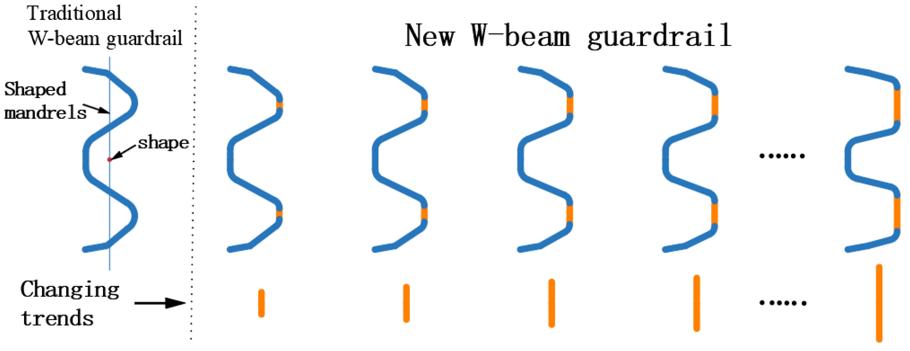
Additionally, the cross-sectional shape of the W-beam guardrail exhibits a wavy contour, similar to a shell structure [19,20,21]. This unique contour shape ensures both structural mechanical performance and lightweight characteristics. In optimizing the structure of the new guardrail beam, the same wavy shell structure is adopted. The area of the sections further from the centroidal axis is gradually increased, with more area distributed farther from the centroidal axis to improve the moment of inertia of the cross-section. The optimization approach for the W-beam guardrail can be referenced in the schematic shown in Figure 1.
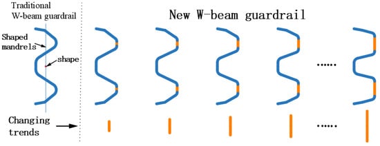
Figure 1.
Optimization strategy for the W-beam guardrail.
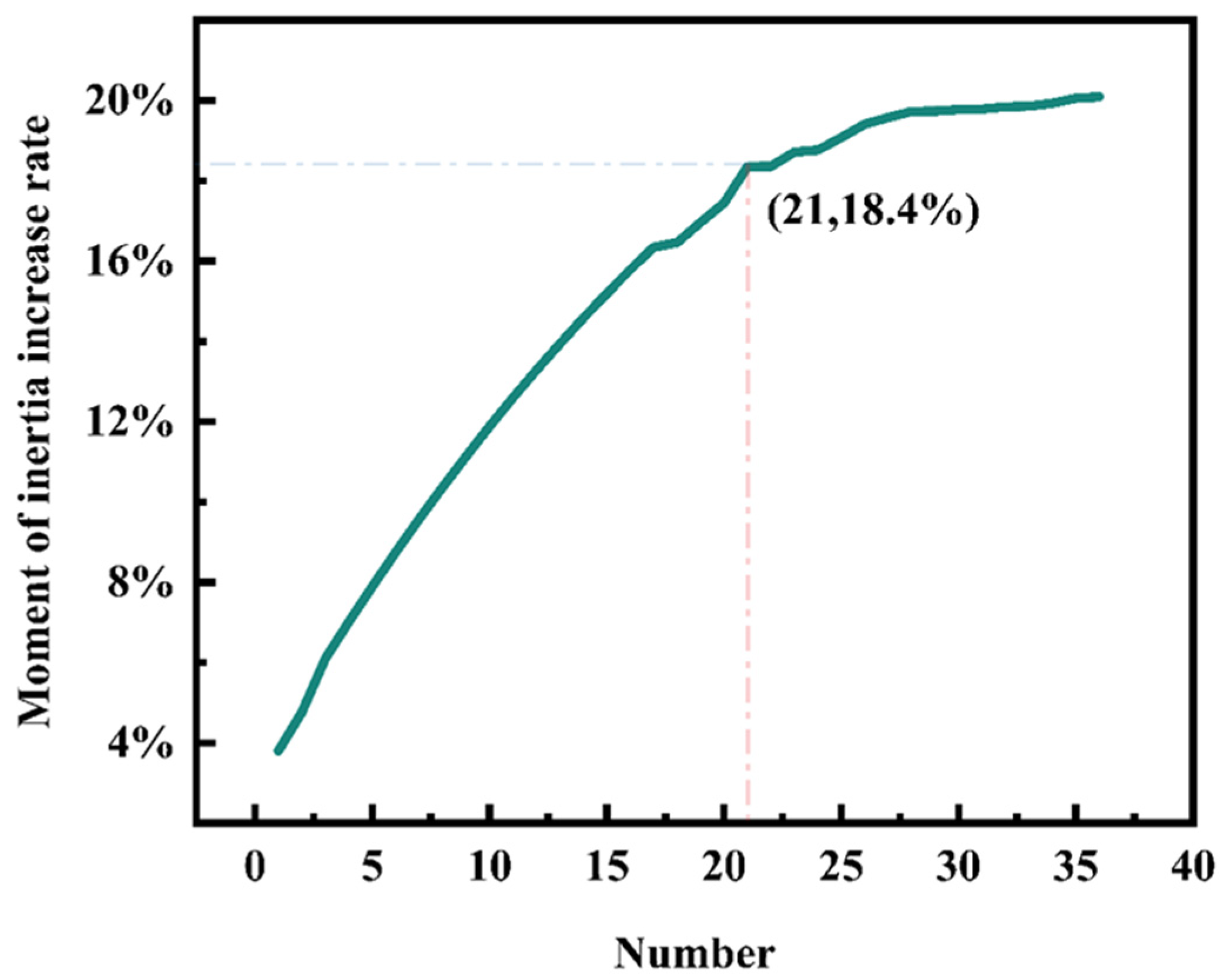
Based on the above optimization strategy for the guardrail beam cross-section, a total of 36 new guardrail cross-sections were designed. Compared to the traditional cross-sections, these new cross-sections exhibit varying degrees of increase in cross-sectional area. The shape and area of a cross-section both influence its moment of inertia. To facilitate the exploration of the impact of cross-sectional shape on the moment of inertia, the thickness of the 36 new types of guardrails was adjusted to match the cross-sectional area of traditional W-beam guardrails. For example, at a thickness of 3 mm, the cross-sectional area of the 21st new guardrail increased by 8.1% compared to the traditional guardrail. The thickness of the 21st new guardrail was adjusted to 2.76 mm to match the cross-sectional area of the 3 mm thick traditional guardrail. The adjusted 21st new guardrail exhibited an 18.4% increase in moment of inertia compared to the traditional guardrail, as prominently indicated in Figure 2. Detailed results are shown in Figure 2.

Figure 2.
Curves of rate of increase in moment of inertia of the 36 new types of section.
It is important to note that the 2.76 mm thickness of the new corrugated beam presents challenges in practical manufacturing. To facilitate the adoption of the new W-beam guardrail, all subsequent discussions in this paper will pertain to the Type 21 guardrail with a thickness of 3 mm.
2.2. Mechanism Analysis
In the optimization method for the W-beam guardrail, the gradual reduction of the shell structure characteristics of the guardrail may adversely affect its protective performance. Therefore, to clarify the impact of this change on the impact deformation resistance of the guardrail, LS-DYNA was used to establish collision simulation models for the 36 new types of guardrail beams, and their deformations under the same collision conditions were compared.
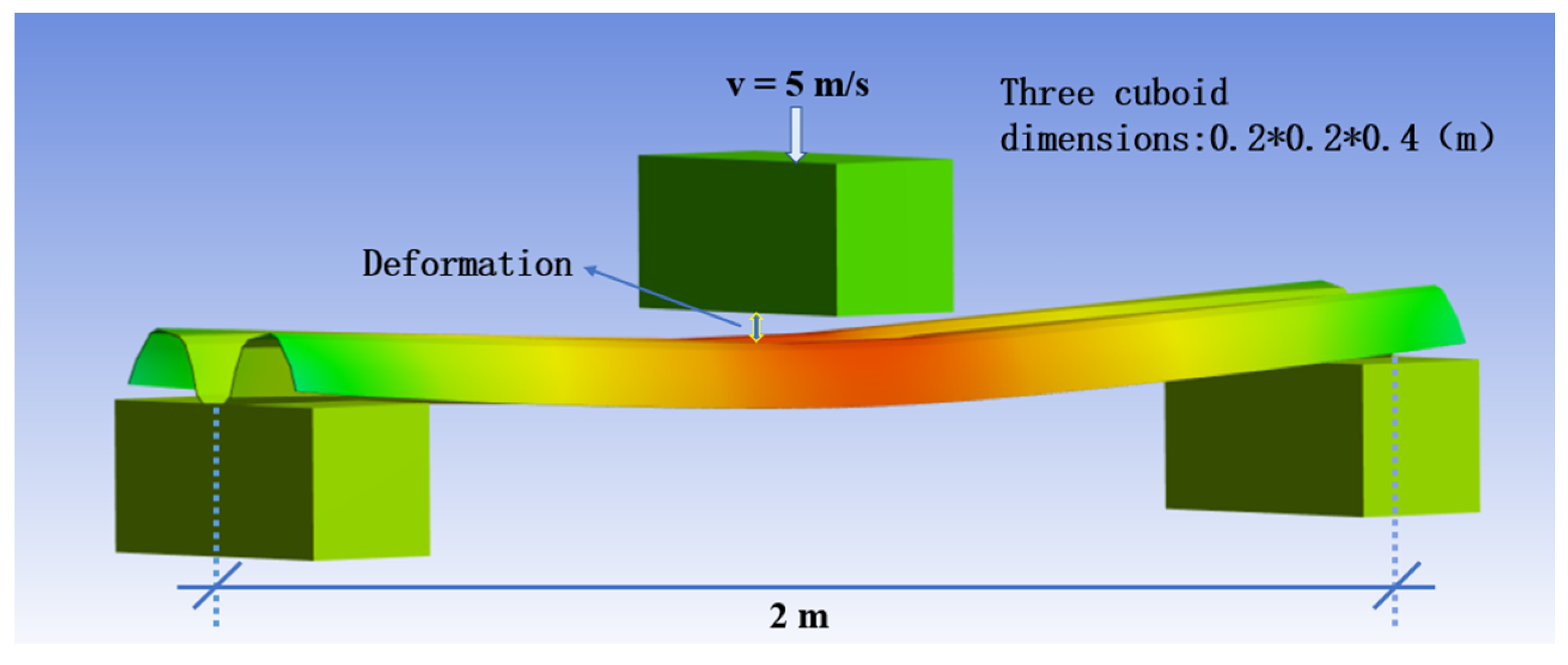
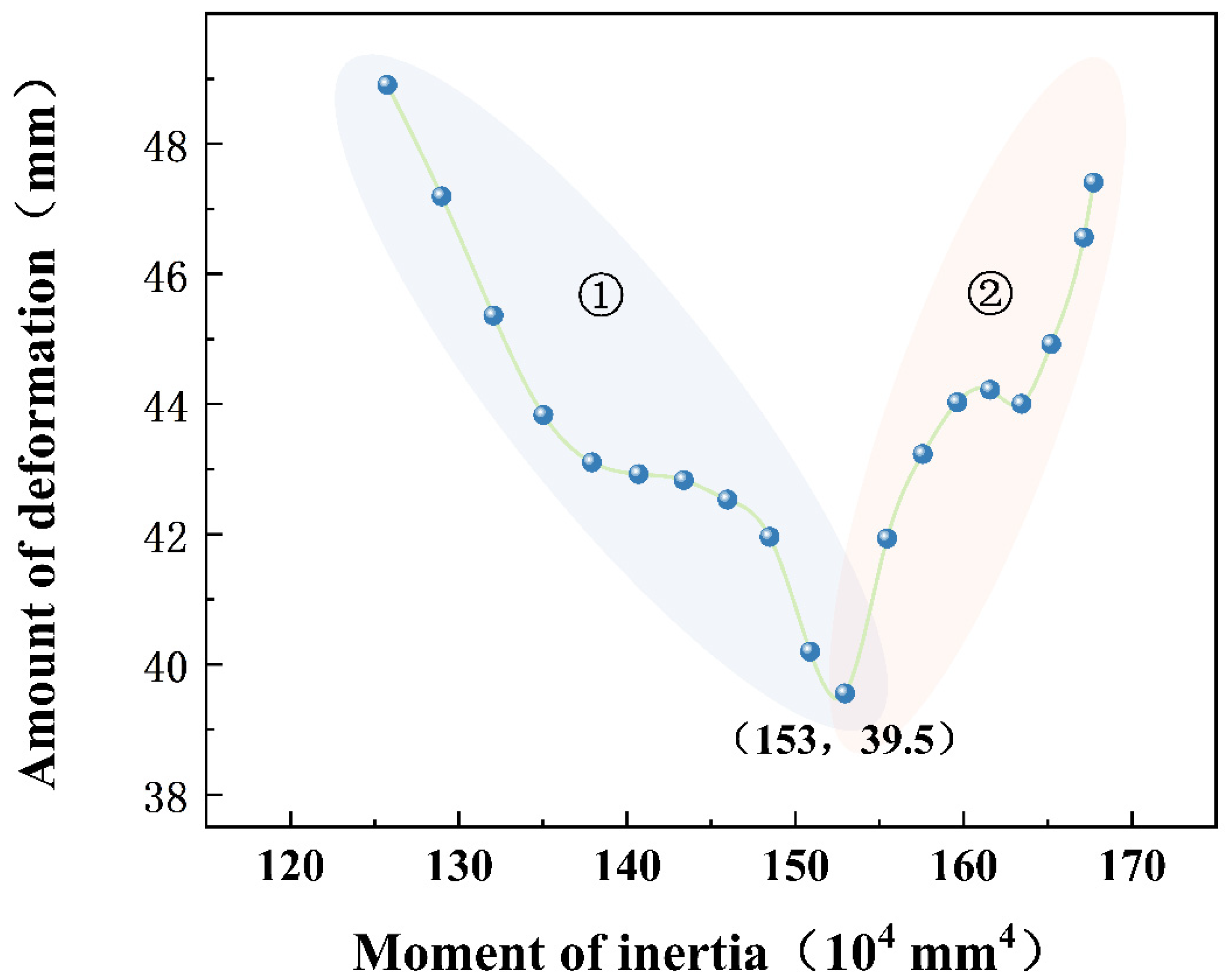
The dimensions of the 36 new guardrail beams are based on actual measurements, with a uniform thickness of 3 mm. To ensure the validity of the collision model, the wave beam was treated as a flexible body, and Q235 nonlinear structural steel, which accurately reflects plastic deformation, was used as the material. Shell elements were employed for modeling. In the context of instantaneous collisions, damping and dynamic coefficients typically do not significantly influence the results. Consequently, damping and dynamic coefficients were not incorporated in the analysis settings. Additionally, the beam was rigidly connected to the supports at both ends, and the six degrees of freedom of the supports were constrained. The impactor was positioned directly above the mid-span of the beam and given an initial velocity of 5 m per second to simulate the collision. Details of the collision model setup are shown in Figure 3. Nineteen representative sections were selected from the results, and their deformation during the collision was plotted against the moment of inertia. The results are shown in Figure 4.
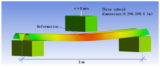
Figure 3.
Schematic diagram of the wave beam collision model.

Figure 4.
Deformation curve of the wave beam collision model.
The curve as a whole exhibits a trend of first descending and then rising from region ➀ to region ➁ (Figure 4), where the characteristics of the curve undergo a significant change. In region ➀, there is a pronounced negative correlation between the moment of inertia and the deformation (correlation coefficient r = −0.96, significance coefficient p < 0.001). Conversely, in region ➁, a significant positive correlation is observed between the moment of inertia and the deformation (correlation coefficient r = 0.95, significance coefficient p < 0.001).
In region ➁, with the increase in moment of inertia, the deformation increases. This is because the new cross-sections in region ➁ lose the characteristics of shell structures. During the collision process, the wave-shaped beam undergoes localized lateral deformation, leading to a rapid attenuation of the cross-sectional moment of inertia, resulting in a decrease in the stiffness of the wave-shaped beam and thus an increase in deformation.
It should be noted that when the wave-shaped beam undergoes excessive deformation, its bending stiffness will sharply decrease, at which point longitudinal tension begins to play a role in resisting the impact force.
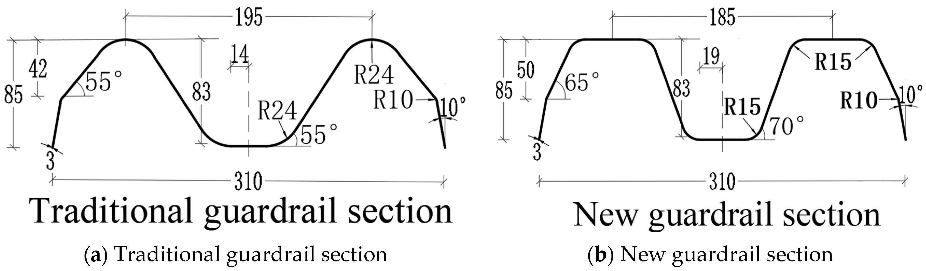
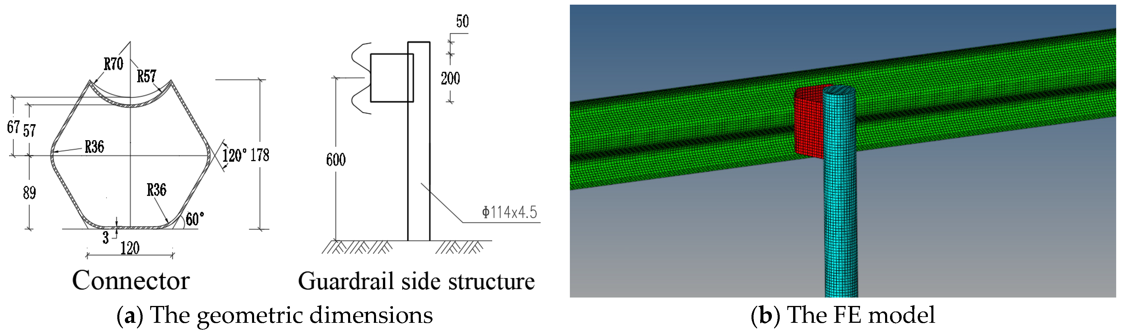
After comprehensive consideration, the final design of the cross-section dimensions for the new guardrail beams was determined. Under the condition of the same thickness of 3 mm, the cross-sectional area of the new guardrail beams increased by 8% compared to traditional guardrails, and the moment of inertia increased by 28%. The cross-sectional dimensions of the traditional W-beam guardrail beams comply with relevant specifications [22,23], as shown in Figure 5a, while the dimensions of both the traditional and new guardrail beams are depicted in Figure 5b, and their geometric characteristics are compared in Table 1.
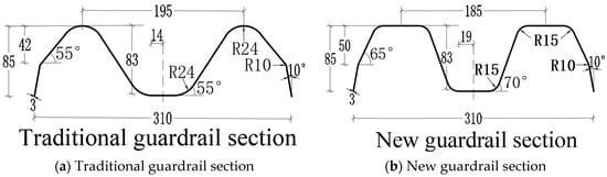
Figure 5.
Line shape and size of guardrail section.

Table 1.
Cross-section comparison of guardrail beams.
2.3. The Differential Equation for the Wave-Shaped Beam
In Section 2.1, the theoretical analysis did not account for the effect of energy absorption by the shell of the wave-shaped beam. Therefore, introducing a correction coefficient, Equation (8) is calibrated, yielding
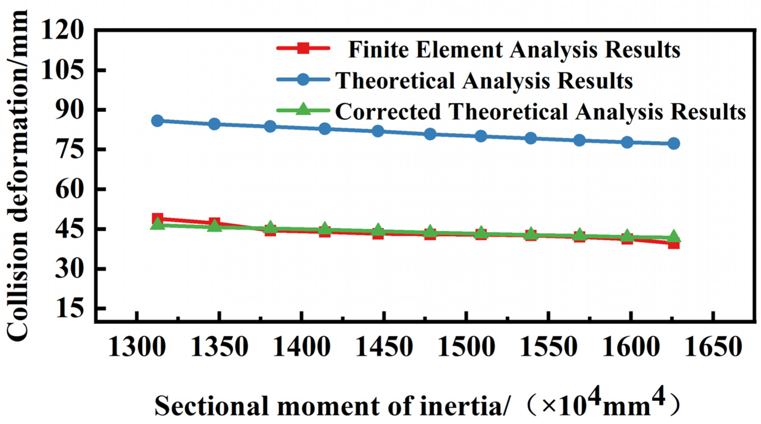
The simulation analysis of different sections of the new guardrail was conducted with boundary conditions as depicted in Figure 3. The relevant parameters are as follows: the momentum of the colliding object is 625 kg·m/s, the span of the wave-shaped beam is 1.6 m, the unit length mass of the wave-shaped beam is 12.5 kg/m, and the material’s elastic modulus is 206 GPa. The results are shown in Figure 6, yielding a correction coefficient of 0.67.
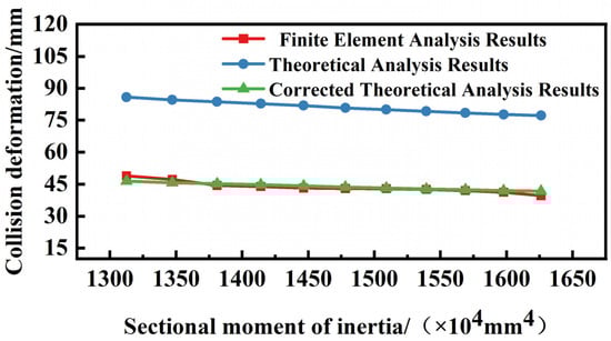
Figure 6.
Results after the deformation calculation formula has been revised.
In the preceding discussion, the corrugated guardrail was simplified as a beam–column system, neglecting the characteristics of the corrugated beam shell structure. Simultaneously, comparing different new guardrail sections revealed a consistent proportional relationship between theoretical and simulation results. Therefore, a correction factor needs to be introduced to rectify errors arising from the simplification assumptions. Correction factors [24] are commonly applied in engineering as follows. The classical Euler-Bernoulli beam theory assumes that the cross-section of the beam remains perpendicular to the neutral axis throughout the bending process. This assumption approximately holds true for long and slender beams but introduces significant errors for short and stubby beams. To address this issue, in 1921, Timoshenko beam theory proposed a first-order shear deformation theory, introducing shear correction factors to rectify errors stemming from simplified assumptions. The values of correction factors are typically determined through theoretical analysis, experimental measurements, and numerical simulations [25].
It should be noted that the formulas mentioned above have undergone various simplifications, providing only a qualitative analysis of the effects of the waveform beam and offering a simple yet effective approach for optimizing guardrails. For high-speed vehicle-guardrail collisions, the physical properties can be regarded as complex functions varying along the axis position, typically necessitating numerical methods to solve their motion equations. Therefore, in the subsequent analysis of vehicle–guardrail collisions, this study employed the finite element software LS-DYNA for numerical analysis.
3. Finite Element Model Construction
In this study, a small car CAE finite element model was chosen as the collision test vehicle, with dimensions of 4010 mm in length, 1670 mm in width, 1270 mm in height, a wheelbase of 2590 mm, and a weight of 1254 kg.
Establishing the model of the W-beam guardrail, the materials and geometric structures of the guardrail were set according to the “Highway Traffic Safety Facility Design Code” (JTG/T D81-2017) [26] and the “Highway Traffic Safety Facility Design Specification” (JTG D81-2017) [27].
3.1. Finite Element Model of the Vehicle
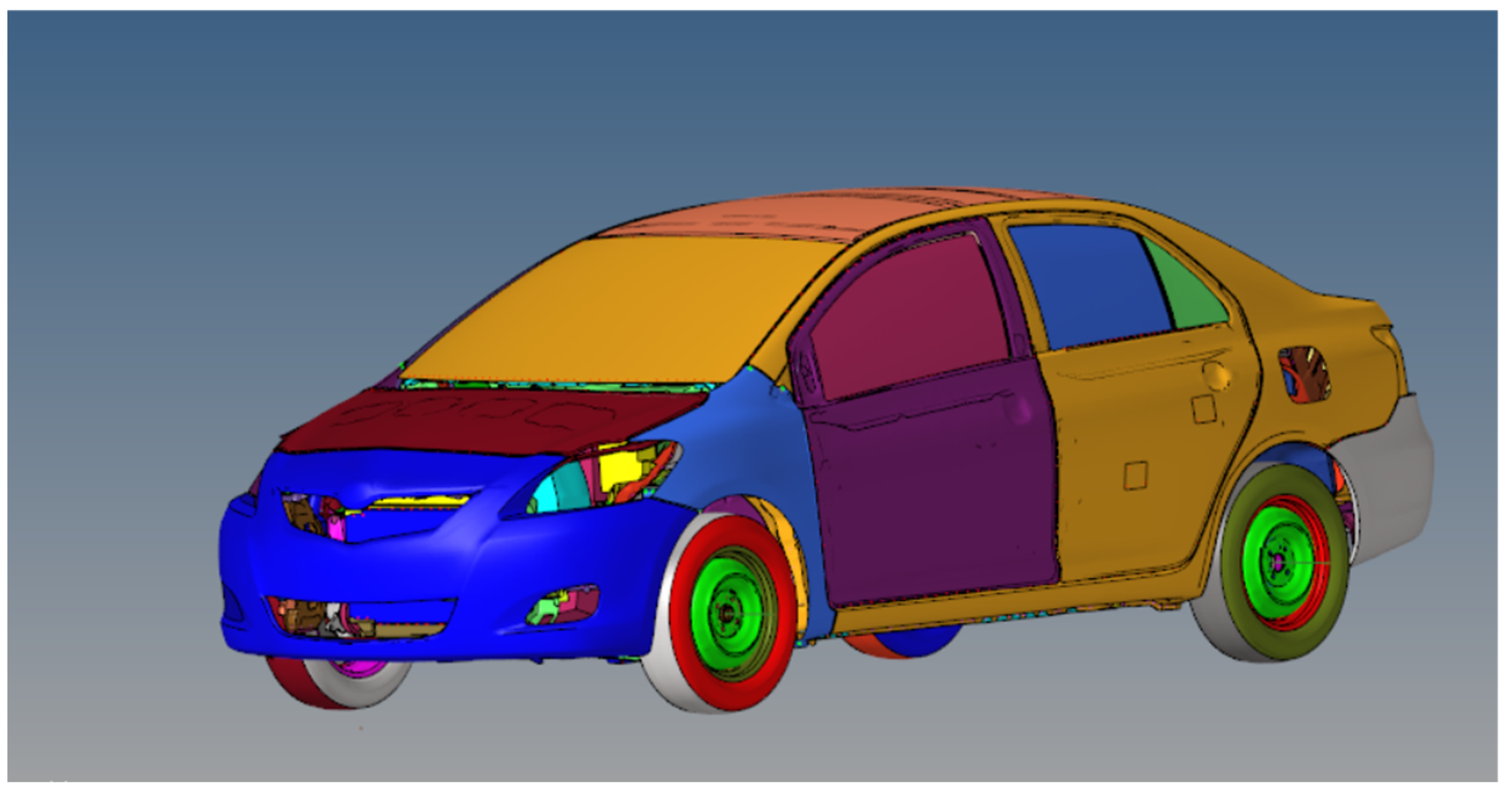
Based on relevant studies [22,28,29,30,31,32], a finite element model of the vehicle comprising 779 components was constructed. This model comprehensively considers the interactions among various components of the vehicle during a collision. Furthermore, the main components of the vehicle, including the body structure, frame, suspension, chassis, and tires, typically undergo complex elastic-plastic deformations during actual collisions. In the finite element model, these critical components are endowed with elastic–plastic deformation characteristics to more accurately simulate post-collision responses. Mesh refinement was performed on each component to ensure the reliability of the collision process between the vehicle and the W-beam guardrail.
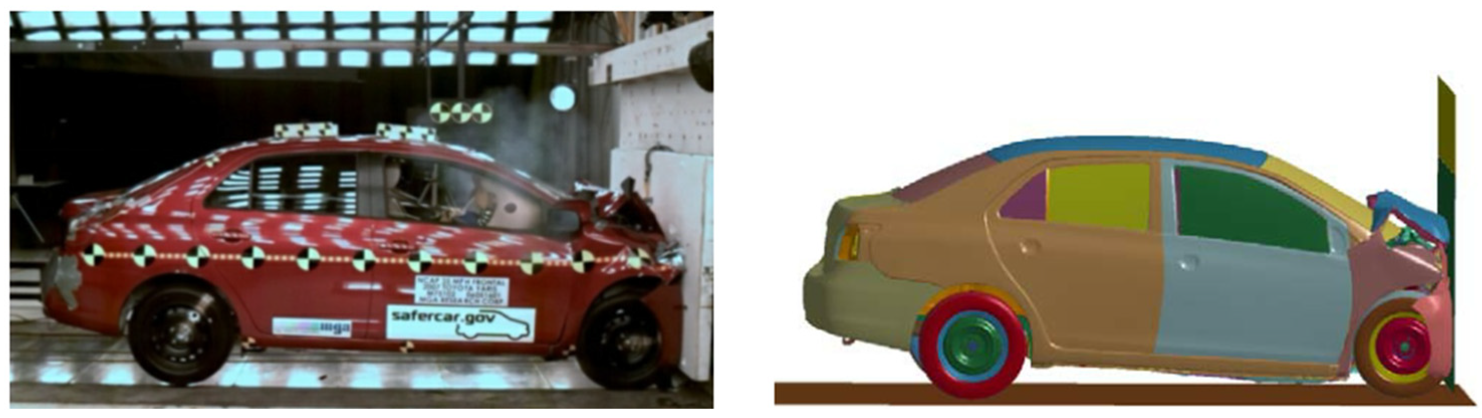
The finite element model of the vehicle originates from a small car model developed by the National Crash Analysis Center (NCAC) in the early 21st century. This model is based on the actual structure and parameters of a real vehicle. Information regarding material properties, stiffness, and mass was derived from experiments. After conducting rigid wall collision tests, the results showed good agreement with real-world vehicle collision experiments. The finite element model of the vehicle can be obtained for download at https://www.nhtsa.gov/crash-simulation-vehicle-models. The NCAC rigid wall collision test is shown in Figure 7, and the finite element model of the vehicle is shown in Figure 8.
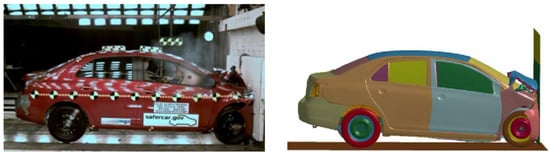
Figure 7.
NCAC vehicle rigid wall collision test.

Figure 8.
Finite element model of the vehicle.
3.2. Establishment of the Novel W-Beam Guardrail Model
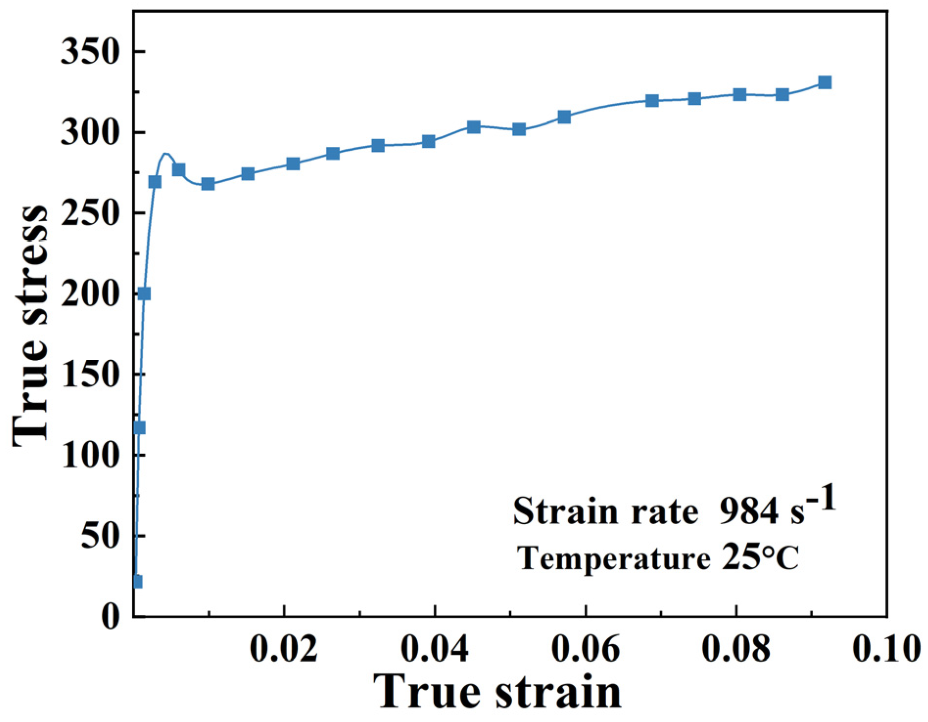
The W-beam guardrail is a common road safety facility composed of cylindrical posts, W-beam rails, and blockouts. According to relevant standards, all parts of the traditional W-beam guardrail are made of Q235 [33] material. The W-beam rail of the novel aluminum alloy guardrail is made of Al 6061-T6 [34] material, while the posts and blockouts are made of Q235 material. In practical situations, the components of the guardrail are fixed together using bolts or welding. When establishing the finite element model, the connections between the three components of the guardrail are simplified as rigid connections. Additionally, the posts of this type of guardrail are buried 1.25 m into concrete with a spacing of 4 m. When creating the finite element model, the contact between the posts and the ground is constrained to six degrees of freedom to simulate real-world conditions. In the collision model, the yield stress of Al 6061-T6, as referenced in [34], is set to 290 MPa. The stress–strain curve is depicted in Figure 9. The dimensional information of the posts and blockouts, as well as the construction details of the guardrail, are shown in Figure 10a.
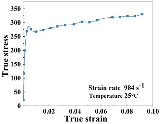
Figure 9.
The constitutive relationship of Al 6061-T6 at room temperature and high strain rates.
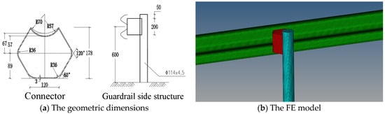
Figure 10.
The localized finite element model of the guardrail.
In the finite element collision model, finite element simulation models of traditional steel guardrails, novel steel guardrails, and novel aluminum alloy guardrails are established. To compare experimental results, only the guardrail W-beam is replaced in the finite element model, while the remaining collision conditions remain unchanged. The local finite element models of the guardrail are depicted in Figure 10b.
4. Vehicle Collision Conditions and Evaluation Criteria
During collisions between vehicles and traffic safety barriers, the collision energy is absorbed and dissipated in the deformation of the vehicle body and the protective barrier, mitigating the impact of the collision. Ideally, traffic safety barriers should possess controllable guiding properties and good cushioning characteristics, aiming to protect the safety of both the colliding vehicle and its occupants without posing a threat to other vehicles in traffic.
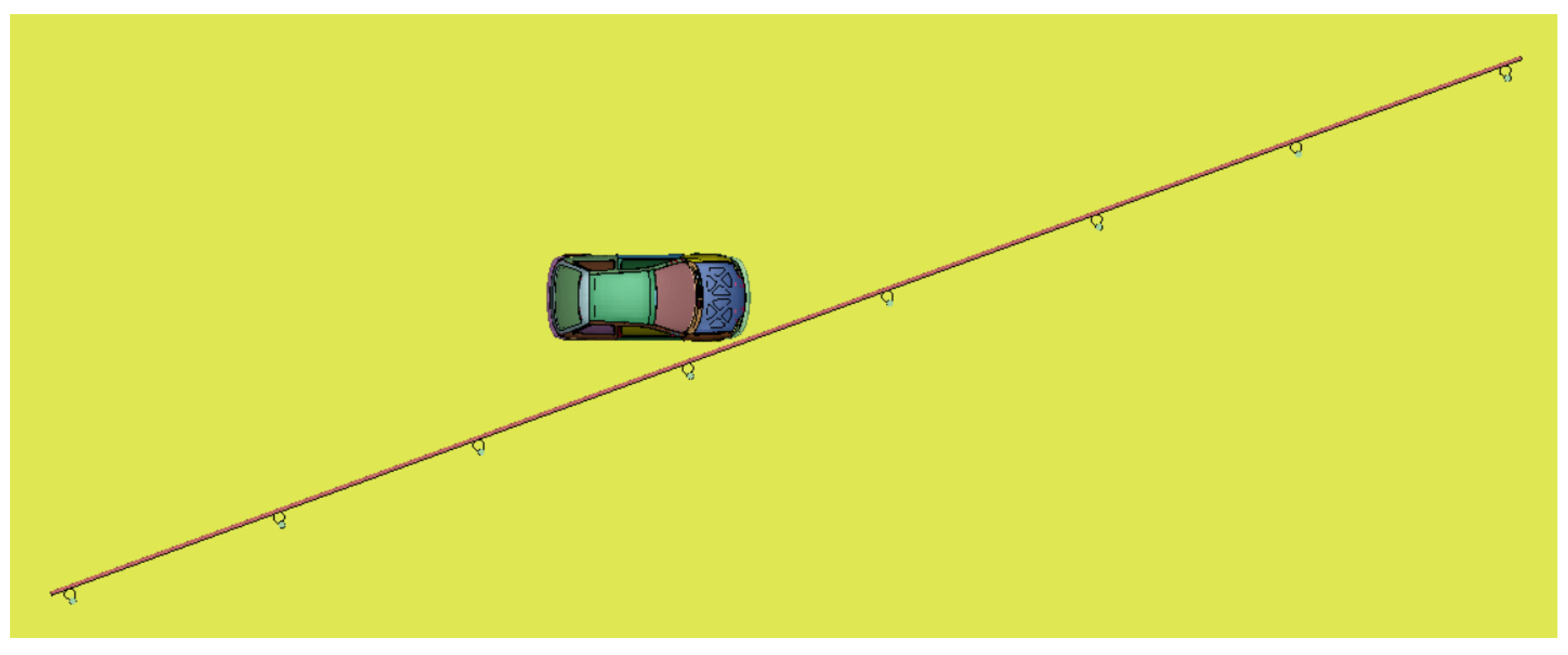
In simulating car–barrier collisions, the collision angle, velocity, and position of the vehicle are fundamental collision conditions. In this context, at the same velocity, collision damage is directly proportional to the collision angle. Increasing the collision angle results in increased damage to both the vehicle and the barrier. Collision damage reaches its maximum in a 90-degree frontal collision. According to the “Highway Guardrail Safety Performance Evaluation Standard” (JTG/T F83-01-2004) [35], a collision angle of 20 degrees and the actual vehicle speed within the first 6 m of the collision point should be selected as the basic collision conditions. Additionally, the standard specifies the minimum total installation length of the guardrail and stipulates that the collision position should be one-third of the total length of the guardrail. In this simulation experiment, we followed this standard and selected a collision angle of 20 degrees and a collision speed of 100 km per hour, with the dimensions of the barrier being 7 × 4 m and a total length of 28 m. The collision position was set at one-half of the total length of the barrier. The car–barrier collision model is depicted in Figure 11.

Figure 11.
Vehicle–barrier collision model.
When assessing the safety performance of barriers, consideration should be given to three aspects: human, vehicle, and barrier. For semi-rigid wave barriers, it is essential to ensure that their maximum dynamic deformation does not exceed the standard-specified maximum dynamic deformation of 1000 mm to guarantee their safety performance. In collision experiments without the use of crash test dummies, if the maximum accelerations experienced by occupants in the vehicle in the lateral, longitudinal, and vertical directions do not exceed 20 g, it is considered that occupants will not sustain fatal injuries in such collisions. Regarding vehicle collision trajectories, it is crucial to ensure that the collision vehicle model meets requirements and that phenomena such as vehicle intrusion or rollover do not occur during collisions with the barrier. Additionally, the barrier should exhibit good guidance properties to prevent vehicles from deviating at excessive angles and intruding into other lanes, thus avoiding secondary collisions.
According to existing relevant research [36,37,38] and evaluation standards [35], the most commonly used evaluation indicators include the maximum dynamic deformation produced during the barrier–vehicle collision, the acceleration of the vehicle’s center of mass, and the energy absorption curve of the barrier. These indicators can be used to assess the safety performance of the barrier. The LS-DYNA solver module is employed to solve the finite element model of the barrier–vehicle collision and obtain relevant data, thereby comprehensively evaluating the barrier’s performance.
5. Finite Element Simulation Results
Utilizing the finite element method, a collision simulation model between vehicles and guardrails was constructed and imported into LS-DYNA software for simulation analysis to evaluate the protective effectiveness of the new W-beam guardrail. In the simulation analysis, particular emphasis was placed on assessing the energy absorption capacity of the W-beam guardrail during collision, maximum dynamic deformation, as well as its impact on the vehicle’s center of gravity acceleration and operational state to evaluate its protective performance.
5.1. Guardrail Energy Absorption
During the simulation of vehicle–guardrail collisions, energy absorption is one of the crucial metrics to evaluate guardrail performance. The energy absorption equation in finite element analysis is expressed by Equation (10).
where represents the energy of the configuration at a certain time, represents the volume of the configuration at a certain time, represents the deviatoric stress tensor, represents the strain rate tensor, represents the pressure, and represents the volumetric viscous resistance.
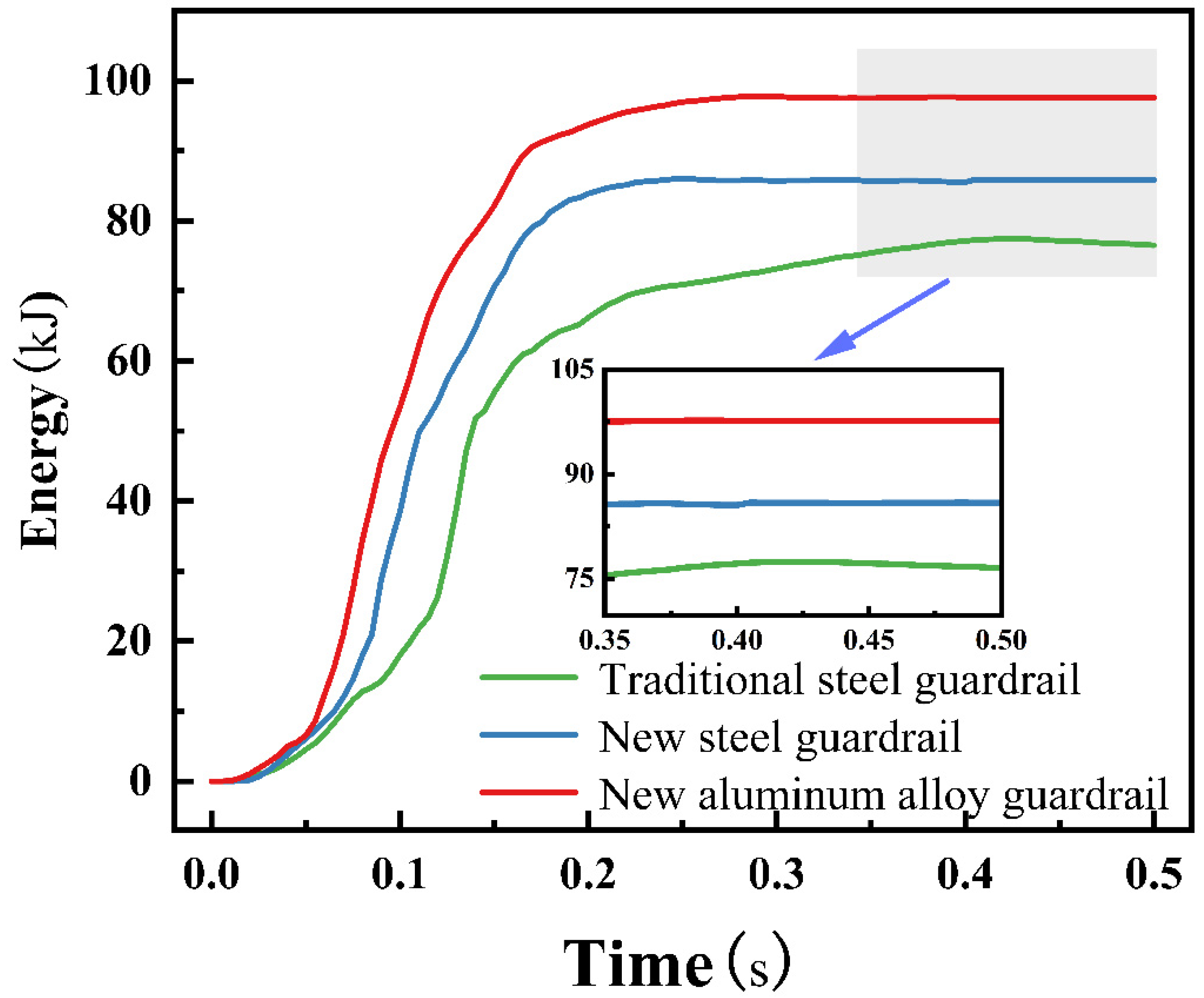
The energy absorption curves of the guardrails, as shown in Figure 12, exhibit a tendency to stabilize after reaching a certain threshold. The traditional steel guardrail absorbs a maximum of 77.0 kJ of energy at 0.48 s, while the new steel guardrail achieves the highest energy absorption of 85.9 kJ at 0.46 s. In contrast, the new aluminum alloy guardrail demonstrates optimal energy absorption performance, reaching a maximum of 97.7 kJ at 0.39 s.
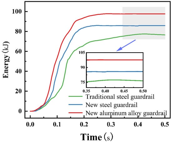
Figure 12.
Absorption energy curves.
5.2. The Maximum Dynamic Deformation of the Guardrail
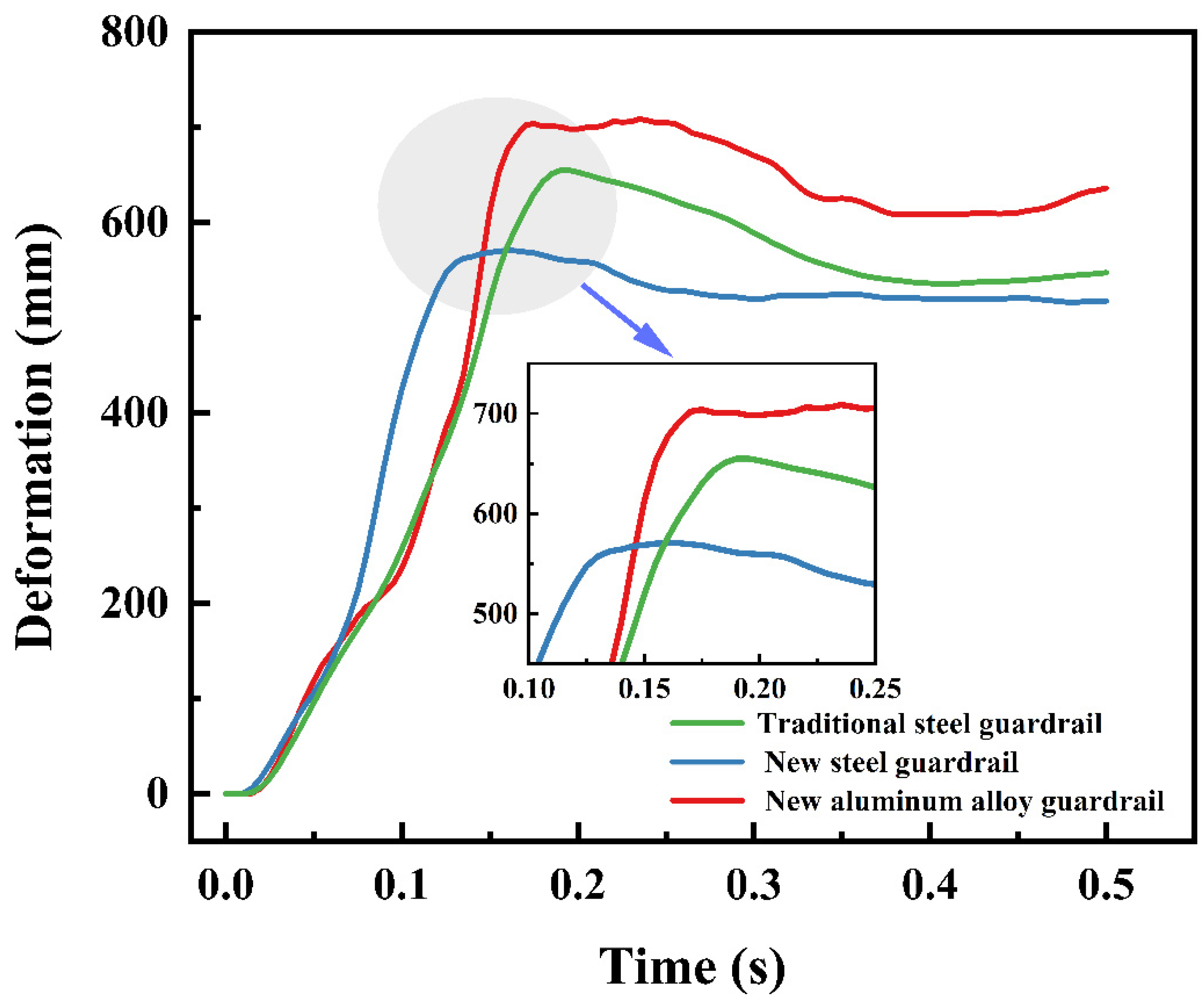
When a vehicle collides with the W-beam guardrail, the guardrail undergoes dynamic deformation to absorb collision energy. Due to the elastoplastic characteristics of the guardrail material, there is a slight reduction in deformation at the maximum deformation point, causing the deformation curve to exhibit a slight rebound. Specific results are shown in Figure 13. In the tests, the maximum dynamic deformation of the traditional steel guardrail was 647 mm at 0.19 s, while that of the new steel guardrail was 564 mm at 0.14 s. Meanwhile, the new aluminum guardrail reached a maximum deformation of 711 mm at 0.17 s.

Figure 13.
Dynamic deformation of the guardrail.
During the collision process, the maximum dynamic deformation of the guardrail is less than 1000 mm, which prevents the vehicle from impacting directly and induces a certain degree of redirection to return to the original lane, thereby mitigating the impact of traffic accidents. It is noteworthy that in severe collisions, the guardrail may fracture, leading to the vehicle losing control and running off the road.
5.3. Vehicle’s Center of Mass Acceleration
According to relevant standards, the evaluation criterion for the buffering function of highway guardrails is the acceleration at the vehicle’s center of mass after the collision. During the collision process, the maximum allowable acceleration at the center of mass of the vehicle is limited to 20 g. The center of mass acceleration of the vehicle reflects the magnitude of acceleration experienced by occupants during a collision. In collision experiments without the use of crash test dummies, the center of mass acceleration of the vehicle is considered a reliable evaluation indicator for assessing the risk to occupants in a collision accident.
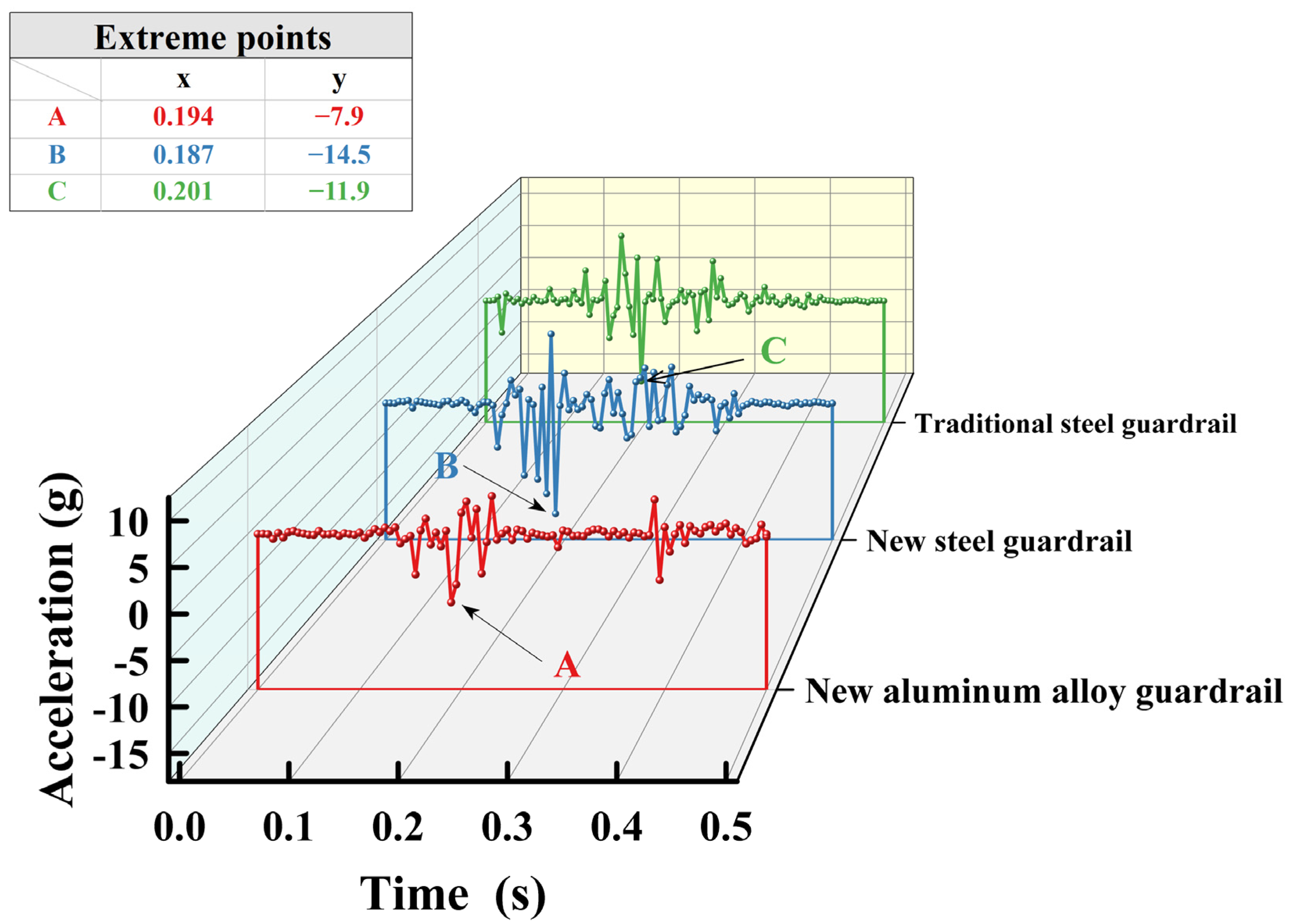
As shown in Figure 14, during the collision process, the three types of guardrails have different effects on the absolute value of the vehicle’s center of mass acceleration. Specifically, for the traditional steel guardrail, the maximum acceleration is −11.9 g at 0.201 s, for the new steel guardrail, the maximum acceleration is −14.5 g at 0.187 s, and for the new aluminum guardrail, the maximum acceleration is −7.9 g at 0.194 s. This indicates that all three types of guardrails have good buffering performance, and their maximum accelerations are below 20 g.
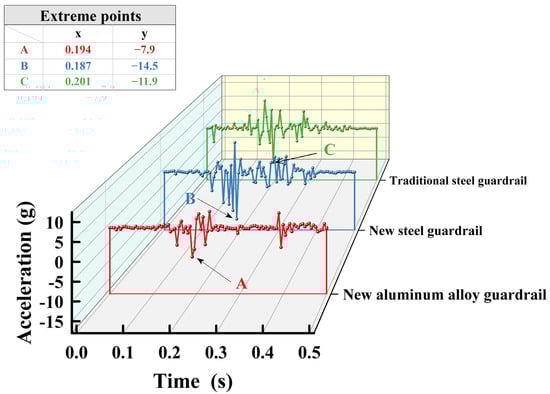
Figure 14.
Acceleration of body center of mass during collision.
6. Discussion
The structural optimization method discussed in Section 2 is equally applicable to traditional three-wave guardrails. By altering the shape of the three-wave guardrail, the cross-sectional moment of inertia of the new three-wave guardrail beams increased by 42% under the same thickness, surpassing the 28% increment of the new two-wave guardrail. Therefore, applying this optimization method to optimize three-wave guardrails is expected to yield superior results compared to two-wave guardrails. The primary focus of this paper is to introduce the conceptual framework and theoretical derivation of this optimization method, and specific performance enhancements resulting from the optimization of three-wave guardrails will not be demonstrated herein.
Wave guardrails absorb energy through plastic deformation during collisions. Plastic deformation serves as an energy absorption mechanism, where energy is utilized to overcome interatomic forces within the material, resulting in permanent changes in shape. Plastic deformation plays a crucial role in energy absorption, as the energy-absorbing capability of crash barriers essentially depends on the extent of plastic deformation after the collision.
In the theoretical analysis of Section 2.3, it was assumed that the momentum of the impacting object is entirely converted into the deformation of the beam, without considering the influence of the shell structure of the wave beam. This assumption resulted in an overestimation of the theoretical calculation results, although it does not affect the subsequent conclusions. The research findings indicate that during the collision process, the shell structure of the W-beam guardrail can absorb over 50% of the impact energy, demonstrating a significant effect in terms of energy absorption. Additionally, the revised theoretical formula aligns well with the finite element results, allowing for the calculation of the maximum dynamic deformation of the wave beam after collision.
During the optimization of the cross-section as depicted in Figure 1, the guardrail gradually loses its shell structure characteristics, leading to an increase in moment of inertia and deformation. This negatively impacts the guardrail’s resistance to collisions. Through the analysis of the results in Figure 4, an optimized new W-beam guardrail cross-section, as shown in Figure 5, was selected. Compared to the traditional cross-section, this new design enhances the moment of inertia while effectively absorbing 67% of the collision energy through its shell structure features, as illustrated in Figure 6. Consequently, it significantly reduces dynamic deformation during collisions, thus enhancing the guardrail’s protective performance.
7. Conclusions
Based on the comparative analysis of the finite element models of three types of W-beam guardrails under the same collision conditions, with the traditional steel guardrail as reference, and through collision simulation experiments, the differences in key indicators such as maximum dynamic deformation, vehicle acceleration, and guardrail energy absorption were compared. The following conclusions were drawn:
- (1)
- According to theoretical derivation, the collision deformation of waveform beams is inversely proportional to the square root of their bending stiffness. After optimization of the waveform beams, their cross-sectional moment of inertia increased by 28.6%, and the deformation in finite element analysis decreased by 12.8%, confirming the accuracy of this law.
- (2)
- Under the condition of the same guardrail material, compared with the traditional guardrail, the material cost of the new W-beam guardrail increased by 8.1%, while the maximum dynamic deformation decreased by 12.8%, and the energy absorption increased by 11.6%. This reduces the risk of serious injury to occupants when the vehicle runs off the road in severe collisions. This indicates that optimizing the linear shape of the guardrail section to increase its moment of inertia can effectively improve the protective performance of the guardrail. This optimization strategy provides a valuable reference for guardrail design and is expected to promote the improvement of guardrail safety performance in practice.
- (3)
- Compared with the traditional steel guardrail, the new aluminum alloy guardrail re-duces the vehicle’s center of mass acceleration by 33.6% and increases the energy absorption by 26.0% after collision. It exhibits better toughness and energy absorption capacity during a collision, better mitigating the impact force generated by the vehicle collision and providing better protection for occupants.
Author Contributions
Conceptualization, L.W., J.L. and Z.T.; methodology, L.W. and Z.T.; software, L.W.; validation, X.H. and Z.T.; formal analysis, R.L.; investigation, D.C.; resources, X.H.; data curation, L.W.; writing—original draft preparation, L.W.; writing—review and editing, all authors; visualization, J.L. and Z.T.; supervision, R.L.; project administration, X.H.; funding acquisition, X.H. All authors have read and agreed to the published version of the manuscript.
Funding
This work was supported by the National Nature Science Foundation of China [grant number 51568029].
Institutional Review Board Statement
Not applicable.
Informed Consent Statement
Not applicable.
Data Availability Statement
The raw data supporting the conclusions of this article will be made available by the authors on request.
Conflicts of Interest
The authors declare no conflicts of interest.
References
- Liu, W.; Tang, Z.; Lu, F.; Qiao, Y.; Zhang, C. Analysis and Experimental Study on the Guided Wave Phase Characteristics of Highway Guardrail Posts. J. Vib. Shock 2017, 36, 223–228. [Google Scholar]
- Dan, X. Design and Research of Auxiliary Manipulatorfor Highway Guardrail Pile Driver. Master’s Thesis, China University of Mining and Technology, Beijing, China, 2022. [Google Scholar]
- Ji, G. Feasibility Study of Fiberglass Reinforced Composite Materials Applied to Road Guardrails. Urban Roads Bridg. Flood Control 2006, 49–50+7. [Google Scholar] [CrossRef]
- Fu, X.; Liu, J.; Sun, N.; Sha, H. Experimental and Numerical Simulation of Impact Compression Mechanical Properties of 6061-T6 Aluminum Alloy. J. Disaster Prev. Mitig. Eng. 2023, 43, 1076–1083. [Google Scholar] [CrossRef]
- Manes, A.; Peroni, L.; Scapin, M.; Giglio, M. Analysis of Strain Rate Behavior of an Al 6061 T6 Alloy. Procedia Eng. 2011, 10, 3477–3482. [Google Scholar] [CrossRef]
- Shankar, M.R.; Chandrasekar, S.; Compton, W.D.; King, A.H. Characteristics of Aluminum 6061-T6 Deformed to Large Plastic Strains by Machining. Mater. Sci. Eng. A 2005, 410, 364–368. [Google Scholar] [CrossRef]
- Zhong, Z. Finite Element Method Analysis of Vehicle Durability. Automot. Eng. 1994, 16, 1–6. [Google Scholar]
- Jaber, M.M.; Ali, M.H.; Abd, S.K.; Abosinnee, A.S.; Malik, R.Q. Simulation Research on the Collision between Freight Cars and Expressway Three-Wave Beam Steel Guardrail. Multimed. Tools Appl. 2023, 1–22. [Google Scholar] [CrossRef]
- Sun, S.; Li, H.; Zhu, C.; Mei, K.; Jiang, H.; Sun, Y.; Huang, H. Study on the Anti-Collision Performance of Basalt Fiber Reinforced Polymer Beam–Column Guardrail. Compos. Struct. 2021, 276, 114588. [Google Scholar] [CrossRef]
- Yao, J.; Wang, B.; Hou, Y.; Huang, L. Analysis of Vehicle Collision on an Assembled Anti-Collision Guardrail. Sensors 2021, 21, 5152. [Google Scholar] [CrossRef]
- Yao, J.; Zhang, J.; Huang, L.; Xu, J.; Wang, B. Analysis of Anti-Collision Performance of a New Assembled Rolling Guardrail. In Structures; Elsevier: Amsterdam, The Netherlands, 2023; Volume 47, pp. 246–259. [Google Scholar]
- Liang, J.; Yao, S.; Li, B.; Chen, Y.; Du, Z.; Xu, T. Collision Simulation of Temporary Traffic ProtectionFacilities Based on Finite Element Analysis. Highway 2020, 65, 269–277. [Google Scholar]
- Huang, H.; Mo, J.; Yang, J. The Application of Finite Element Analysis to Guardrail Designand Occupant Protection. Comput. Simul. 2003, 135–139. [Google Scholar]
- Hou, S.; Tan, W.; Zheng, Y.; Han, X.; Li, Q. Optimization Design of Corrugated Beam Guardrail Based on RBF-MQ Surrogate Model and Collision Safety Consideration. Adv. Eng. Softw. 2014, 78, 28–40. [Google Scholar] [CrossRef]
- Yin, H.; Xiao, Y.; Wen, G.; Fang, H. Design Optimization of a New W-Beam Guardrail for Enhanced Highway Safety Performance. Adv. Eng. Softw. 2017, 112, 154–164. [Google Scholar] [CrossRef]
- Yin, H.; Zhang, L.; Liu, Z.; Fan, W.; Wu, X.; Wen, G. Crash Analysis and Evaluation of a New Separate W-Beam Guardrail on Highways Using the Finite Element Method. Eng. Struct. 2023, 278, 115551. [Google Scholar] [CrossRef]
- Triantafyllou, M. Dynamics of Cables and Chains. Shock Vib. Dig. 1987, 19, 3–5. [Google Scholar] [CrossRef]
- Iandiorio, C.; Salvini, P. Elastic-Plastic Analysis with Pre-Integrated Beam Finite Element Based on State Diagrams: Elastic-Perfectly Plastic Flow. Eur. J. Mech.-A/Solids 2023, 97, 104837. [Google Scholar] [CrossRef]
- Bradshaw, R.; Campbell, D.; Gargari, M.; Mirmiran, A.; Tripeny, P. Special Structures: Past, Present, and Future. J. Struct. Eng. 2002, 128, 691–709. [Google Scholar] [CrossRef]
- Arbocz, J.; Starnes, J.H., Jr. Future Directions and Challenges in Shell Stability Analysis. Thin-Walled Struct. 2002, 40, 729–754. [Google Scholar] [CrossRef]
- Lamiel, C.; Hussain, I.; Ogunsakin, O.R.; Zhang, K. MXene in Core–Shell Structures: Research Progress and Future Prospects. J. Mater. Chem. A 2022, 10, 14247–14272. [Google Scholar] [CrossRef]
- JTG D81-2006; Specifications for the Design of Highway Traffic Safety Facilities. Transportation Press: Beijing, China, 2006.
- JTG/T D81-2006; Detailed Rules for Design of Highway Traffic Safety Facilities. Transportation Press: Beijing, China, 2006.
- Dong, S.; Alpdogan, C.; Taciroglu, E. Much Ado about Shear Correction Factors in Timoshenko Beam Theory. Int. J. Solids Struct. 2010, 47, 1651–1665. [Google Scholar] [CrossRef]
- Moon, J.; Lim, N.-H.; Lee, H.-E. Moment Gradient Correction Factor and Inelastic Flexural–Torsional Buckling of I-Girder with Corrugated Steel Webs. Thin-Walled Struct. 2013, 62, 18–27. [Google Scholar] [CrossRef]
- JTG/T D81-2017; Highway Traffic Safety Facility Design Code. Transportation Press: Beijing, China, 2017.
- JTG D81-2017; Highway Traffic Safety Facility Design Specification. Transportation Press: Beijing, China, 2017.
- Noorsumar, G.; Rogovchenko, S.; Robbersmyr, K.G.; Vysochinskiy, D. Mathematical Models for Assessment of Vehicle Crashworthiness: A Review. Int. J. Crashworthiness 2022, 27, 1545–1559. [Google Scholar] [CrossRef]
- Gao, G.; Wang, S. Crashworthiness of Passenger Rail Vehicles: A Review. Int. J. Crashworthiness 2018, 24, 664–676. [Google Scholar] [CrossRef]
- Lee, D.-C.; Han, C.-S. CAE (Computer Aided Engineering) Driven Durability Model Verification for the Automotive Structure Development. Finite Elem. Anal. Des. 2009, 45, 324–332. [Google Scholar] [CrossRef]
- Lee, D.; Woo, Y.; Lee, S.; Han, C. Design Consideration of the Nonlinear Specifications in the Automotive Body. Finite Elem. Anal. Des. 2008, 44, 851–861. [Google Scholar] [CrossRef]
- Yang, R.-J.; Akkerman, A.; Anderson, D.; Faruque, O.; Gu, L. Robustness Optimization for Vehicular Crash Simulations. Comput. Sci. Eng. 2000, 2, 8–13. [Google Scholar] [CrossRef]
- Cui, N. Crash Simulation of Vehicle-Guardrails and Optimization of theRail Post. Master’s Thesis, Dalian University of Technology, Dalian, China, 2018. [Google Scholar]
- Zhang, H.-R.; Zhao, H.; Wang, R.; Liang, X.-X.; Zhu, Y. Coupling Influences of Elevated Temperature and Strain Rate on the Behaviour of 6061-T6 Aluminium Alloy Used as Construction Material. Structures 2022, 40, 596–606. [Google Scholar] [CrossRef]
- JTG/T F83-01-2004; Standard for Evaluation of Safety Performance of Highway Guardrails. Transportation Press: Beijing, China, 2004.
- Soltani, M.; Moghaddam, T.B.; Karim, M.R.; Sulong, N.H.R. The Safety Performance of Guardrail Systems: Review and Analysis of Crash Tests Data. Int. J. Crashworthiness 2013, 18, 530–543. [Google Scholar] [CrossRef]
- Reid, J.D.; Sicking, D.L.; Faller, R.K.; Pfeifer, B.G. Development of a New Guardrail System. Transp. Res. Rec. 1997, 1599, 72–80. [Google Scholar] [CrossRef]
- Ross, H., Jr.; Sicking, D.; Zimmer, R.A.; Michie, J.D. Recommended Procedures for the Safety Performance Evaluation of Highway Features; Transportation Research Board: Washington, DC, USA, 1993. [Google Scholar]
Disclaimer/Publisher’s Note: The statements, opinions and data contained in all publications are solely those of the individual author(s) and contributor(s) and not of MDPI and/or the editor(s). MDPI and/or the editor(s) disclaim responsibility for any injury to people or property resulting from any ideas, methods, instructions or products referred to in the content. |
© 2024 by the authors. Licensee MDPI, Basel, Switzerland. This article is an open access article distributed under the terms and conditions of the Creative Commons Attribution (CC BY) license (https://creativecommons.org/licenses/by/4.0/).