Article

Sound-Absorbing, Thermal-Insulating Material Based on Non-Woven Fabrics Mixed with Aerogel Particles

1
Collaborative Research Laboratory, Graduate School of Advanced Science and Engineering, Hiroshima University, Hiroshima 739-8527, Japan
2
Applied Chemistry Program, Graduate School of Advanced Science and Engineering, Hiroshima University, Hiroshima 739-8527, Japan
3
Technical Research Center, Mazda Motor Corporation, Hiroshima 730-8670, Japan
4
Department of Mechanical Engineering, Kogakuin University, Tokyo 192-0015, Japan
5
Smart Innovation Program, Graduate School of Advanced Science and Engineering, Hiroshima University, Hiroshima 739-8527, Japan
*
Authors to whom correspondence should be addressed.
Appl. Sci. 2024, 14(13), 5368; https://doi.org/10.3390/app14135368
Submission received: 11 May 2024 / Revised: 14 June 2024 / Accepted: 15 June 2024 / Published: 21 June 2024

Abstract

:

Featured Application

Porous material with high sound absorption and thermal insulation properties.

Abstract

The automotive industry is rapidly advancing toward the electrification of vehicles. Battery electric vehicles present unique challenges in heat and noise control due to the absence of an internal combustion engine. These challenges arise from the stringent operating temperature requirements of batteries and the distinct characteristics of their power sources, such as differences in rpm and mounting positions compared to traditional engines. To address these issues, porous sound-absorbing materials and porous insulation materials are commonly employed. Conversely, there is an increasing demand for materials that are both lightweight and compact yet capable of providing excellent sound absorption and thermal insulation. Although porous sound absorbers and insulators are similar, they differ in the microstructure required to achieve high performance, specifically in the size and connectivity of their fluid phases. This increases the challenge of integrating superior sound absorption and insulation properties within the same material. In this study, computational microstructure modeling was employed to develop a non-woven fabric composed of flattened ellipsoidal particles with nanoporosity. This innovative material demonstrates exceptional thermal insulation and sound absorption characteristics attributable to its nanoporosity and high tortuosity.

1. Introduction

Governments worldwide have set targets for carbon neutrality, prompting the automotive industry to accelerate the adoption of electric-drive vehicles (EDVs) as a strategy to meet these objectives. In addition to facilitating the spread of EDVs, the industry focuses on optimizing vehicle performance through advanced material applications. For thermal management, high-performance insulation materials are utilized to maintain appropriate temperatures for batteries, power conversion systems, and the vehicle interior. In terms of noise and vibration damping, the absence of an internal combustion engine noise reveals road and wind noise, which were previously masked. Additionally, noise and vibrations generated by motors and other power sources require efficient damping using high-performance sound-absorbing materials. However, meeting all these requirements in the constrained space of a vehicle is challenging, necessitating porous materials that excel in heat insulation and sound absorption.
Thermal conductivity is a key indicator of the performance of thermal-insulating materials. High-performance porous thermal insulation insulates by reducing the heat conduction pathways inside the material: heat conduction in solids, heat conduction in gases, heat convection in gases, and heat radiation. Therefore, it is recognized that the thermal conductivity of a thermal-insulating material depends on the structure inside the material [1,2,3]. Specifically, the porosity or bubble ratio should be increased to reduce heat conduction in solids, or heat conduction path of solids should be lengthened. Furthermore, to reduce heat conduction in gases, heat conduction in gases, and heat radiation, the diameter of porosity and bubbles should be reduced from tens of nanometers to tens of micrometers, or each space should be made independent of the other. On the other hand, the sound absorption coefficient is a key indicator of the performance of sound-absorbing materials. High-performance porous sound-absorbing materials absorb sound by converting sound wave energy into heat energy through viscoelastic damping in solids and viscous damping and heat dissipation at the boundary between gas and solid, which is caused by sound wave penetration into the material. Therefore, it is recognized that, as with thermal insulation, the sound absorption coefficient of a sound-absorbing material depends on the structure inside the material [4,5,6,7,8]. Specifically, to improve viscoelastic damping in solids, the loss factor of the solid should be increased, or the solid should be more easily distorted. Furthermore, to improve viscous damping and heat dissipation at the boundary between gas and solid, the boundary area between gas and solid should be increased, or the path of the gas through which sound waves pass should be lengthened. Increasing the boundary area between gas and solid inside the material or lengthening the path of the gas makes it more difficult for sound waves to penetrate the material. Balancing the two, the diameter of porosity and bubbles should be reduced from tens of micrometers to several millimeters in diameter, and each space should be connected to form a flow path for sound waves to pass through. Thus, it is difficult to achieve both thermal and acoustic properties for porous sound-absorbing materials and porous thermal-insulating materials because the size and structure of the porosity and bubbles for optimum performance are very different.
In recent years, experimental studies have been conducted on nanofiber-based composite materials that achieve both thermal and acoustic properties: Polyvinylidene fluoride by Wu et al. (2016) [9], cellulose by Shen et al. (2021) [10], polyurethane by Zhao et al. (2021) [11], thermoplastic polyurethane (TPU)/polystyrene (PS) by Karaca et al. (2022) [12], polyacrylonitrile (PAN) by Farahani et al. (2022) [13], and other materials have been studied. For example, a study by Karaca et al. on TPU/PS-BSE nanofibers prepared using electrospinning solutions [12] showed that they achieve both 0.050 W/(m·K) as thermal conductivity and 0.5–0.6 as the sound absorption coefficient at about 1000 Hz. Experimental studies have also been conducted on silica aerogel-based materials that achieve both thermal and acoustic properties. With regard to silica and silica–polymer hybrid aerogels, polyimide–silica aerogel composites by Yan et al. (2014) [14], sodium dodecyl sulfate-doped gelatin–silica hybrid aerogels by Sachithanadam et al. (2016) [15], monolithic aerogels and granular aerogels by Merli et al. (2018) [16], and other materials have been studied. With regard to silica aerogel–textiles composites, non-woven polyethylene terephthalate (PET)–silica aerogel blankets by Oh et al. (2009) [17], non-woven PET–aerogel composites by Küçük et al. (2012) [18], cotton non-woven fabric–silica aerogel blanket by Motahari et al. (2015) [19], silica aerogel blanket prepared from sols with varying silica content by Ramamoorthy et al. (2017) [20], aerogel–polyethylene (PE)/PET non-woven bonded blankets by Yang et al. (2019) [21], in situ synthetic silica aerogel/PET blankets by Talebi et al. (2019) [22], glass fiber blankets impregnated with aerogel powder (2–40 μm particle size) by Zahra et al. (2021) [23], and other materials have been studied. For example, a study by Zahra et al. on glass fiber blankets impregnated with aerogel powder [23] showed that the sound absorption coefficient above 700 Hz can only reach about 0.4 at a thickness of 10 mm. Despite these developments, there remains a significant gap in mathematical modeling to comprehend the key physical mechanisms behind the acoustic behavior of aerogels.
Therefore, the authors employed a computational microstructural modeling approach based on materials model-based research (MBR) [24] to predict the thermal insulation and sound absorption properties of porous materials. This method facilitated the development of a porous material that exhibits exceptional thermal insulation and sound absorption properties. The material was engineered by integrating aerogel particles, which are characterized by multiple independent spaces with diameters of several tens of nanometers, into a polyethylene terephthalate (PET) fiber non-woven fabric. The appropriate particle size and particle shape and blending ratio were crucial for achieving the desired properties. The result is a non-woven fabric with heat-insulating and sound-absorbing properties that has improved performance with aerogel particles.
In previous research [25], we discussed a material that insulates and absorbs sound by damping sound waves through vibration in a structure containing fine porous and soft sites. In this study, by incorporating nanoporous ellipsoidal particles with long sides ranging from tens to hundreds of microns into non-woven fabrics with voids of similar dimensions, we enhanced the labyrinthine nature of the sound waves’ traversal through the material. This structure allows the nanoporous particles to provide thermal insulation, while the microporous voids facilitate sound absorption, achieving superior performance in both aspects.

2. Materials and Methods

2.1. Computational Microstructure Modeling Approach Applied to Porous Materials

The computational microstructure modeling approach to predicting the sound absorption properties of porous materials involves the asymptotic homogenization method. This method accounts for the viscosity in the fluid phase and the attenuation due to heat dissipation. It enables the direct derivation of equivalent properties from the microstructure, which is essential for predicting the dynamic properties of the porous absorber. These equivalent properties, when applied to a model of the porous sound absorber, allow for the determination of macroscopic properties such as the sound absorption coefficient. For details on the equations required for each calculation, please refer to previous research [25]. The equations required to derive equivalent properties (microscopic properties) from the microstructure of the porous material and to derive the sound absorption coefficient of the porous material (macroscopic properties) from the derived equivalent properties were implemented in COMSOL Multiphysics (Ver. 5.6, Comsol AB, Stockholm, Sweden). COMSOL Multiphysics with this implemented equation was used to calculate the microscopic and macroscopic properties in this study.
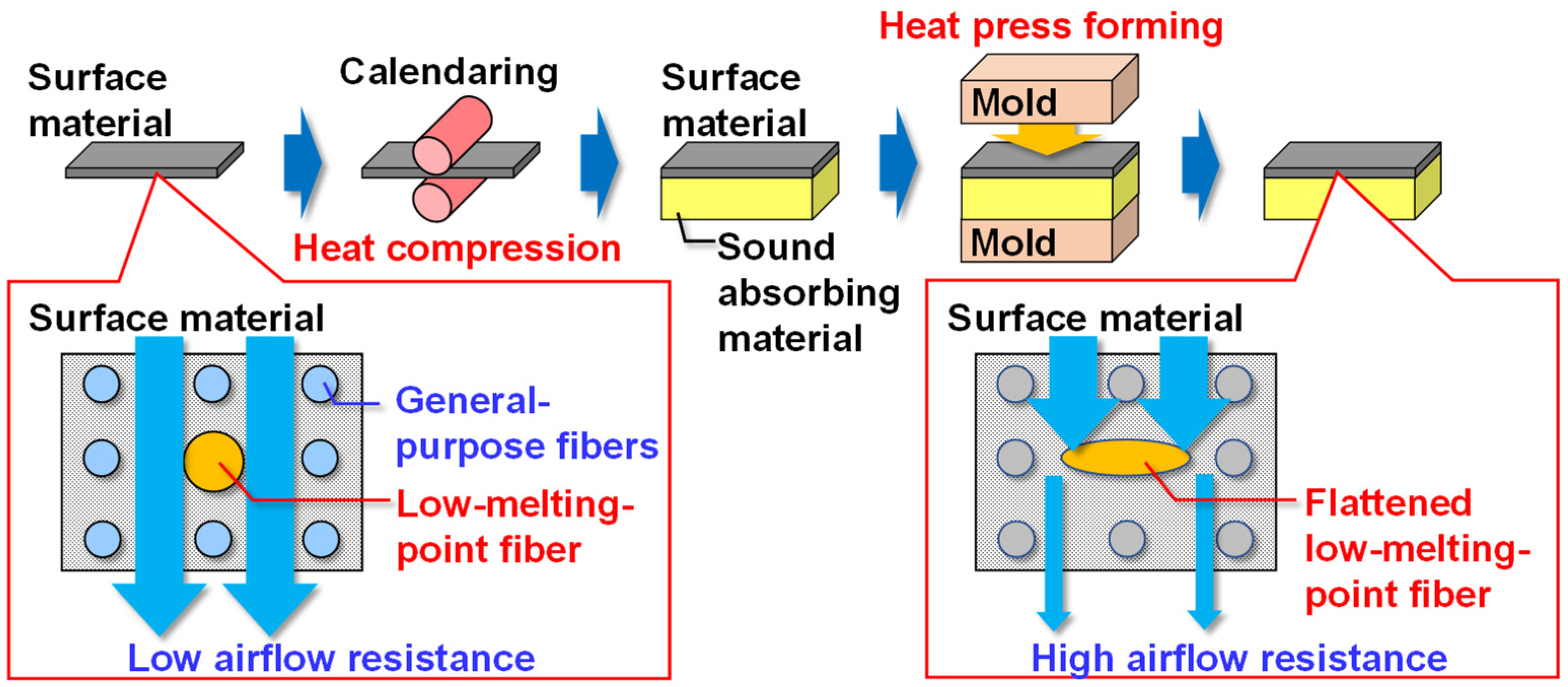
Porous sound absorbers convert the energy of incoming sound waves into heat through viscoelastic damping in the solid phase, viscous damping at the boundary between the fluid and solid phases, and heat dissipation. The effectiveness of sound absorption increases with the number of boundaries between the fluid and solid phases within the material. Therefore, a finer skeletal diameter, ideally at the level of several micrometers, enhances the performance of the sound-absorbing material, although it must also allow for sound wave penetration. Conversely, the skeletal diameter of a high-performance heat insulator should be at the nanometer level to form independent spaces of several tens of nanometers. Since these requirements are inherently contradictory, a novel structure was devised that combines aerogel particles with multiple independent spaces of several tens of nanometers in diameter within the mesh-like channels of the non-woven fabric. This allows for effective sound wave penetration. Using the computational microstructural modeling approach, we designed optimal shapes, particle sizes, and quantities of aerogel particles for this porous material and verified their performance (Figure 1). The meshing sequence for the microstructure was physics-controlled mesh, and for the calculation of microscopic properties, the minimum element size of the solid section was set to be 10 μm or less. In the calculation of macroscopic properties, physics-controlled mesh was also used, and the minimum element size was set to be 9 mm or less.

2.2. Preparation of Porous Materials and Performance Evaluation Methods

A material mirroring the microstructure of the porous sound-absorbing material modeled in Section 2.1 was fabricated. Specifically, non-woven fabrics incorporating particles were produced by mixing pre-mixed polyethylene terephthalate (PET) fibers with a diameter of approximately 7 µm at 60 wt% and low-melt PET fibers with a diameter of approximately 14 µm at 40 wt%.
Sample Opener OP-400 (Takeuchi Seisakusho Co., Ltd., Osaka, Japan) was used for fiber opening and mixing (Figure 2a). The feed conveyor was set at 0.25 m/min and the cylinder roller at 600 rpm. Each fiber clump, pre-measured to a predetermined ratio, was mixed by hand and placed on the feed conveyor so that it was evenly distributed. The sample opener was used to open and mix the fibers twice.
Sample Roller Card SRC-400 (Takeuchi Seisakusho Co., Ltd., Osaka, Japan) was used to card the mixed fibers (Figure 2b). The feed conveyor was set at 0.25 m/min, the cylinder roller at 300 rpm, and the doffer roller at 5 m/min. The fibers mixed by the Sample Opener were placed evenly on the feed conveyor. Carding was performed twice to produce a PET non-woven base sheet with a width of 40 cm and an areal density of approximately 4 g/m2.
A prototype powder feeder (Takeuchi Seisakusho Co., Ltd., Osaka, Japan) for this study was used to spread particles onto a non-woven base sheet (Figure 2c). The powder feeder is equipped with a rotating rubber spatula that shears the particles between the spatula and the walls of the particle stock case and feeds the particles. The bottom of the particle stock case has a hole whose size can be changed, allowing particles of a predetermined size or smaller to be spread at a predetermined rate on a non-woven base sheet with a width of 40 cm. Aerogel particles (Aerogel P100, 0.1 to 4 mm diameter, approximately 0.15 g/cm3, Cabot Corporation, Boston, MA, USA) were used. The elasticity of the rubber spatula and the rotation speed were adjusted so that the particle shape and size distribution were within the target range. A PET non-woven base sheet was passed under the powder feeder at a feed rate of 5 m/min to produce a particle spread PET non-woven base sheet.
The base sheets were stacked to achieve the targeted bulk density, preheated at 150 °C for 10 min, and then cold pressed to 10 mm thickness with a flat die at 80 °C. Thus, a 300 × 300 mm PET non-woven fabric test piece and an aerogel particle-mixed non-woven fabric test piece were prepared. A specimen of the same dimensions was also prepared by laminating one side of this non-woven fabric with a high-airflow-resistance skin material (thickness: 0.20 mm) [26], developed jointly with Maeda Corporation (Figure 3).
The bulk density, fiber content, and particle content of the test pieces were measured using an electronic balance after the specimens were placed in a crucible and heated in an electric furnace at 600 °C for 4 h and then sufficiently cooled. Fiber and particle content were derived from the results of the same measurements on test pieces with 100% fiber content and 100% particle content, respectively.
Structural analysis of the test pieces was performed using an X-ray CT nano3DX (Rigaku Corporation, Tokyo, Japan).
The normal-incidence sound absorption coefficient was measured using the Impedance Tube Kit Type 4206 (Brüel & Kjær, Nærum, Denmark; per ISO 10534-2 [27]). The measurement frequency range was 50–1600 Hz. The measurements were calculated in 1/3-octave bands. The inner diameter of the acoustic tube was 100 mm. The diameter of the specimen was adjusted so that the specimen could be set into the acoustic tube without resistance. Furthermore, the ambient shape of the specimen was fine-tuned, and the sound absorption coefficient measurement was repeated to confirm that the resonance behavior was no longer present, and the final measurement results were obtained.
Flow resistivity, which influences the sound absorption coefficient, was measured using the airflow resistivity meter SIGMA (Mecanum Inc., Sherbrooke, QC, Canada; per ISO 9053-1 [28]). Pressure drop data were measured when air flowed through the specimen at a low flow velocity of 0.5 mm/s. Flow resistivity was calculated from the measured pressure drop, flow velocity, and specimen thickness.
Thermal conductivity was measured using the steady-state thermal conductivity measuring device HFM436/3/1 Lambda (NETZSCH-Gerätebau GmbH, Selb, Germany; per ISO 8301 [29]).

3. Results and Discussion

3.1. Prediction Calculation Result of Sound Absorption Coefficient

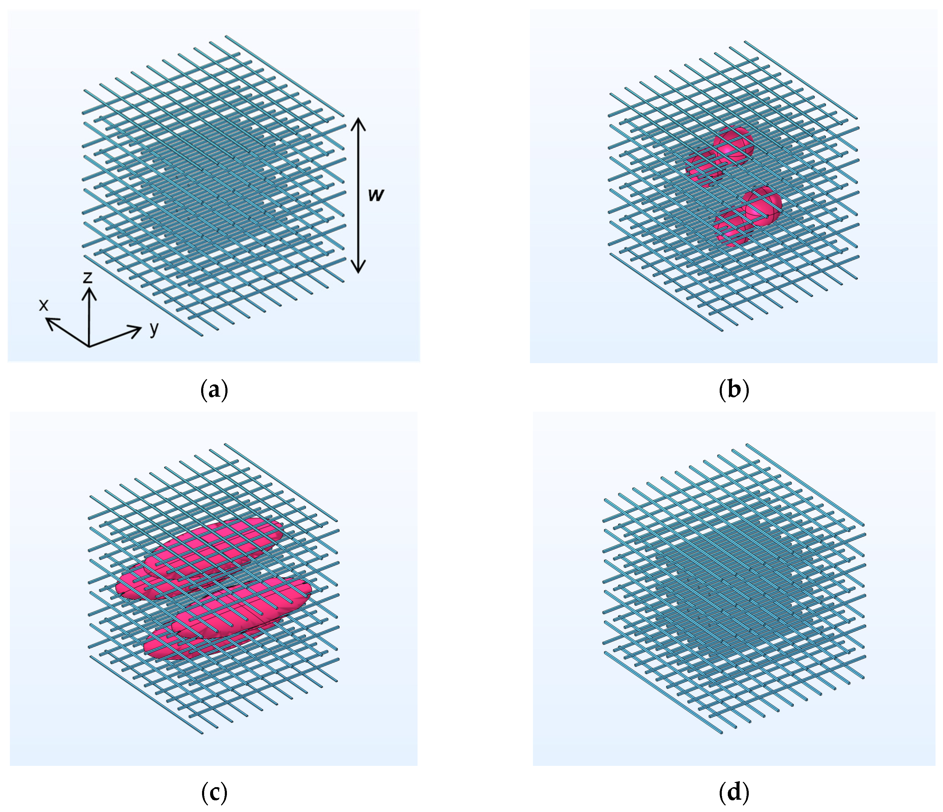
The computational geometry is depicted in Figure 4. The modeled structure mimics a non-woven fabric with a fiber diameter of 10 µm and a porosity of 99%, with a uniform unit cell size of w = 1000 µm (wx = wy = wz = w) (Figure 4a). Particle A in the model presented in Figure 4b is a sphere with a diameter of 220 µm, while particle B in Figure 4c is an ellipsoid measuring 440 × 880 × 27.5 µm. Particles A and B have equivalent volumes. Figure 4d illustrates the geometry of Figure 4a augmented with a fiber mass equivalent to four particles A. The specific gravity of the fiber is assumed to be 1.38 g/cm3 (PET), and that of particles A and B is 0.15 g/cm3 (aerogel). The bulk densities of each configuration and the positions of the centers of gravity of the particles are detailed in Table 1.
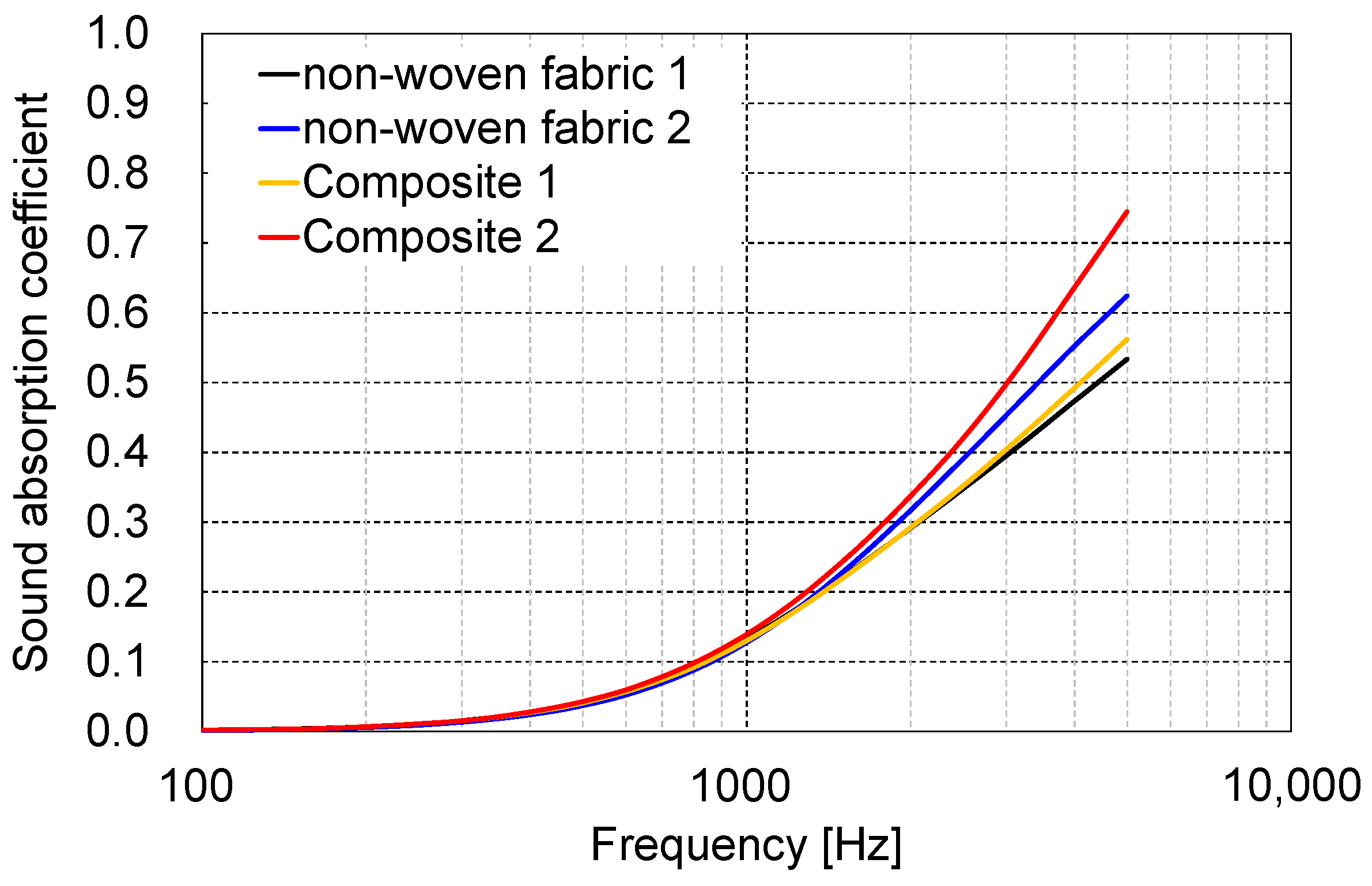
The predictive analysis of the sound absorption coefficient spectrum for a specimen thickness of 10 mm across 1/3-octave bands is illustrated in Figure 5. Table 2 presents the results, showing average sound absorption coefficients derived from the spectra between 500–1600 Hz, 500–3150 Hz, and 1000–5000 Hz. The sound absorption spectra of non-woven fabric 1 and composite 1 were nearly identical. However, a divergence in sound absorption coefficients between non-woven fabric 1 and composite 2 became evident above 400 Hz, with composite 2 demonstrating enhanced sound absorption, particularly in the frequency band above 1000 Hz. This indicates that spherical particles in a non-woven fabric with a bulk density of approximately 13.8 kg/m3 and a particle content rate of about 20 wt% minimally affect the sound absorption coefficient. In contrast, the inclusion of elliptical flattened particles of equivalent weight and volume significantly improves sound absorption. This suggests that particle shape plays a crucial role in influencing the sound absorption coefficient.
Comparing non-woven fabric 2 and composite 2, composite 2 exhibited superior sound absorption, particularly in the higher-frequency range. It was observed that the inclusion of elliptical flattened particles may enhance the sound absorption effect relative to the weight, compared to materials composed solely of fibers. This improvement is believed to stem from the elliptical flattened particles increasing the flow resistivity and tortuosity of the non-woven fabric, which in turn enhances sound absorption (Figure 6).

3.2. Performance Evaluation Result

Based on the calculation results from Section 3.1, we developed a technique to blend flattened aerogel particles oriented against the thickness direction and fabricated aerogel particle-mixed non-woven fabric. Specifically, while producing thin non-woven fabrics using a carding machine, we laid flattened aerogel particles onto these thin fabrics and then laminated them to create non-woven fabrics with the particles aligned along the thickness direction.
Figure 7 presents photographs of test specimens: PET non-woven fabric with a bulk density of 16.2 kg/m3, PET non-woven fabric with a bulk density of 87.2 kg/m3, and Thinsulate, a commonly used automotive sound-absorbing material composed of the fabricated non-woven fabric and the aerogel particle-mixed non-woven fabric. The particle content of the aerogel particle-mixed non-woven fabric was approximately 21.7 wt%, closely matching the 19.5 wt% particle content of particles A and B used in the calculation geometry.
Figure 8 displays the results from the CT analysis of the internal structure of the PET non-woven fabric 1 and the aerogel particle-mixed non-woven fabric, examining fiber-to-fiber distances and particle size distribution. PET non-woven fabric 1, with a bulk density of 16.2 kg/m3, showed a peak distribution of the distance between fibers at about 30 µm. However, the aerogel particle-mixed non-woven fabric, with a bulk density of 87.2 kg/m3, also showed a peak at 30 µm but with fiber distances extending up to 180 µm, indicating wider inter-fiber spacing in areas where particles are present. The median particle diameter, calculated from particle volume assuming a spherical shape, was about 240 µm (particle volume: approximately 7.24 × 106 µm3). This volume is closely aligned with the volume of particles A and B used in the calculation geometry, which is 5.58 × 106 µm3 (particle diameter: 220 µm).
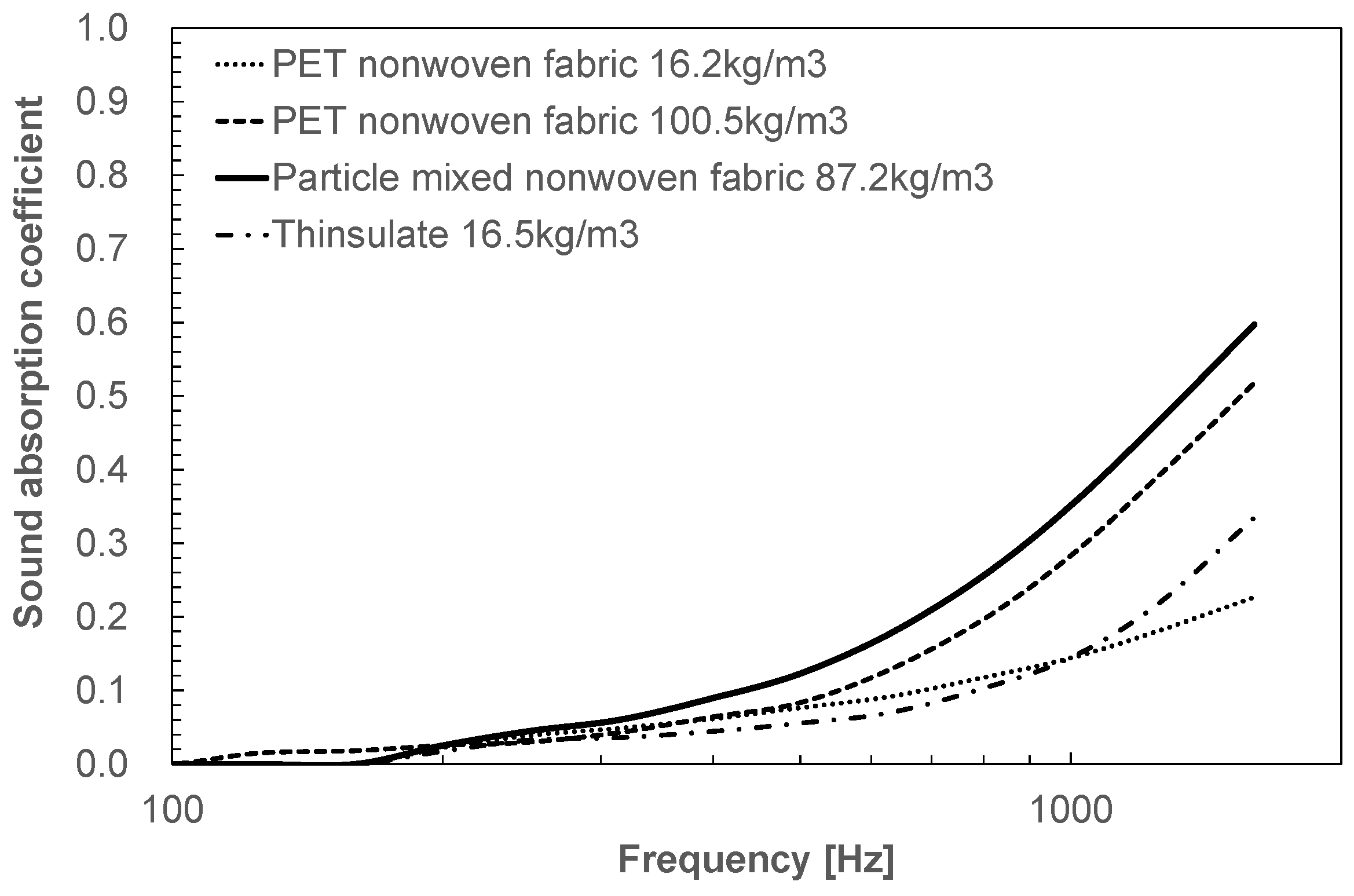
The measured sound absorption coefficients of PET non-woven 1 and PET non-woven 2, with bulk densities of 16.2 and 100.5 kg/m3, respectively, and of aerogel particle-mixed non-woven fabric, with a bulk density of 87.2 kg/m3, and of Thinsulate are shown in Figure 9. PET non-woven fabric 2 demonstrated a higher sound absorption coefficient across a broader frequency range of 100–1600 Hz compared to PET non-woven fabric 1. Additionally, there was no reduction in sound absorption coefficient at higher frequencies up to 1600 Hz.
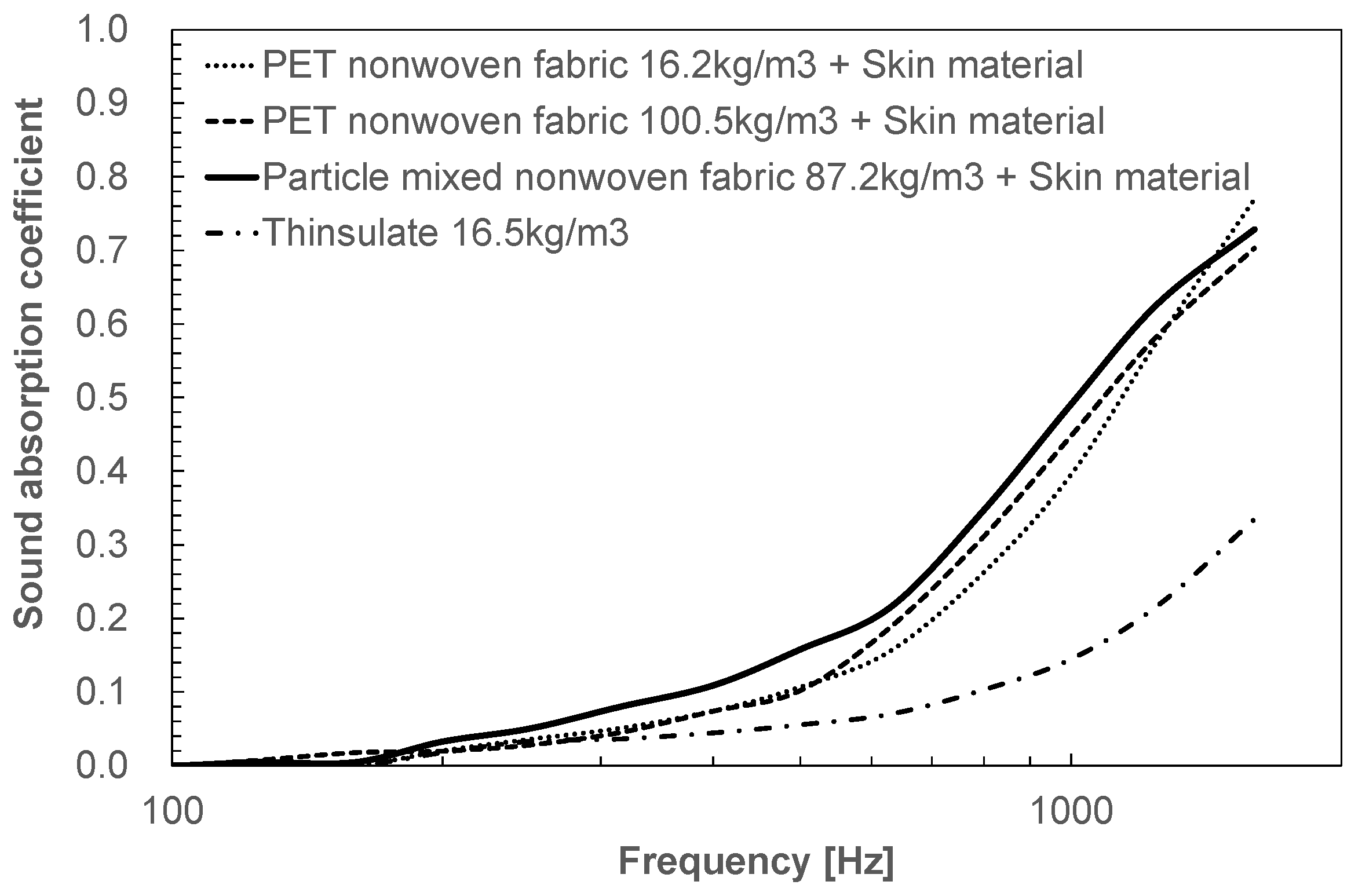
From this, we conclude that PET non-woven fabric is effective in improving the sound absorption coefficient below 1600 Hz for bulk densities up to 100.5 kg/m3. Conversely, the non-woven fabric mixed with aerogel particles demonstrates a higher sound absorption coefficient across most frequency bands of 100–1600 Hz than the PET non-woven fabric 2 with a bulk density of 100.5 kg/m3, despite having a lower bulk density of 87.2 kg/m3. This indicates that the aerogel particles contribute to enhancing the sound absorption coefficient.
Figure 10 displays the sound absorption coefficient measurements for a test specimen of the same shape, where a skin material with high airflow resistance was laminated on one side of the prepared non-woven fabric. Like the PET non-woven fabric, the aerogel particle-mixed non-woven fabric also showed an improvement in sound absorption coefficient, as predicted by the Biot model. Therefore, we deduce that the sound absorption mechanism of non-woven fabrics mixed with aerogel particles aligns with Biot’s theory.
Table 3 presents the average sound absorption coefficient in the 500–1600 Hz range and the measured flow resistivity, which are critical in automotive noise reduction for enhancing speech clarity. In this PET non-woven fabric, the airflow resistance increases with increasing bulk density up to 100.5 kg/m3, and correspondingly, the average sound absorption coefficient in the 500–1600 Hz range also increases. However, the aerogel particle-mixed non-woven fabric exhibits a higher average sound absorption coefficient in the 500–1600 Hz range than PET non-woven fabric 2, despite its lower airflow resistance. The lack of peaks at specific frequencies in the sound absorption spectrum of the aerogel particle-mixed non-woven fabric in Figure 9 suggests that inertia and viscoelastic loss of solids are unlikely to influence the results. From these observations, we infer that the inclusion of aerogel particles enhances the tortuosity, viscous characteristic length, or thermal characteristic length, thereby improving the sound absorption coefficient. The average sound absorption coefficient in the range of 500–1600 Hz was about 2.8 times higher than that of Thinsulate in the specimen made of non-woven fabric mixed with aerogel particles and laminated with a skin material with high airflow resistance.
The thermal conductivities of PET non-woven fabric 1, PET non-woven fabric 2, and non-woven fabric mixed with aerogel particles as well as the thermal conductivity measured when the bulk density is altered by compressing the non-woven fabric within a steady-state thermal conductivity measurement device are presented in Figure 11. PET non-woven fabric reaches a thermal conductivity of about 0.029 W/(m·K) even when the bulk density is increased to approximately 130 kg/m3. Conversely, the non-woven fabric mixed with aerogel particles exhibited a thermal conductivity of about 0.026 W/(m·K), confirming that the aerogel particles enhance the thermal insulation properties of the aerogel particle-mixed non-woven fabric as intended. Compared to Thinsulate, the thermal insulation property of the aerogel particle-mixed non-woven fabric was approximately 1.4 times higher.

4. Conclusions

We developed a non-woven fabric mixed with aerogel ellipsoidal particles that significantly enhances acoustic properties. The thermal conductivity of this material was equivalent to still air (0.026 W/(m·K)), and the average sound absorption coefficient of this material at 500–1600 Hz at a thickness of 10 mm was more than twice that of Thinsulate, a common sound-absorbing material for automobiles. When applied throughout a vehicle’s interior, this material is expected to reduce noise by approximately 40% and improve fuel efficiency by around 4% due to a roughly 30% reduction in energy consumption for air conditioning, although the total weight of the sound-absorbing and heat-insulating materials may increase.
Previously reported porous materials with fine porous and soft sites exhibited excellent heat insulation and sound absorption properties but were brittle and prone to damage. Consequently, their use in automobiles was restricted to locations not exposed to physical stresses. The new aerogel particle-mixed non-woven fabric integrates nanoporous ellipsoidal particles, with long sides ranging from tens to hundreds of microns, into non-woven fabrics with voids of similar dimensions. This composition enhances its resistance to shock and vibration. Additionally, the application of a skin material reduces particle shedding, allowing its use in parts exposed to harsh conditions including external areas and drive units.

Author Contributions

Conceptualization, D.K.; methodology, D.K.; computational analysis, D.K., H.O. and T.Y.; experimental validation, D.K. and M.K.; data curation, D.K.; writing and editing, D.K.; supervision, J.O. All authors have read and agreed to the published version of the manuscript.

Funding

This research received no external funding.

Institutional Review Board Statement

Not applicable.

Informed Consent Statement

Not applicable.

Data Availability Statement

Due to the nature of this research, participants of this study did not agree that their data should be shared publicly. The data presented in this study are available on request from the corresponding author.

Conflicts of Interest

Daiji Katsura, Hiroya Ochiai, and Mitsuyoshi Kawabe were employed by Mazda Motor Corporation. The remaining authors declare that the research was conducted in the absence of any commercial or financial relationships that could be construed as potential conflicts of interest.

References

  1. Shrestha, S.S.; Tiwari, J.; Rai, A.; Hun, D.E.; Howard, D.; Desjarlais, A.O.; Francoeur, M.; Feng, T. Solid and gas thermal conductivity models improvement and validation in various porous insulation materials. Int. J. Therm. Sci. 2023, 187, 108164. [Google Scholar] [CrossRef]
  2. Zhou, Y.; Huang, B.; Cao, B.-Y. Vibrational modes with long mean free path and large volumetric heat capacity drive higher thermal conductivity in amorphous zeolitic imidazolate Framework-4. Mater. Today Phys. 2021, 21, 100516. [Google Scholar] [CrossRef]
  3. Qiu, B.; Bao, H.; Zhang, G.; Wu, Y.; Ruan, X. Molecular dynamics simulations of lattice thermal conductivity and spectral phonon mean free path of PbTe: Bulk and nanostructures. Comput. Mater. Sci. 2012, 53, 278–285. [Google Scholar] [CrossRef]
  4. Gao, K.; van Dommelen, J.A.W.; Geers, M.G.D. Investigation of the effects of the microstructure on the sound absorption performance of polymer foams using a computational homogenization approach. Eur. J. Mech. A Solids 2017, 61, 330–344. [Google Scholar] [CrossRef]
  5. Gao, K.; van Dommelen, J.A.W.; Göransson, P.; Geers, M.G.D. A homogenization approach for characterization of the fluid–solid coupling parameters in Biot’s equations for acoustic poroelastic materials. J. Sound. Vib. 2015, 351, 251–267. [Google Scholar] [CrossRef]
  6. Zieliński, T.G. Microstructure-based calculations and experimental results for sound absorbing porous layers of randomly packed rigid spherical beads. J. Appl. Phys. 2014, 116. [Google Scholar] [CrossRef]
  7. Perrot, C.; Chevillotte, F.; Tan Hoang, M.; Bonnet, G.; Bécot, F.-X.; Gautron, L.; Duval, A. Microstructure, transport, and acoustic properties of open-cell foam samples: Experiments and three-dimensional numerical simulations. J. Appl. Phys. 2012, 111. [Google Scholar] [CrossRef]
  8. Lee, C.-Y.; Leamy, M.J.; Nadler, J.H. Frequency band structure and absorption predictions for multi-periodic acoustic composites. J. Sound. Vib. 2010, 329, 1809–1822. [Google Scholar] [CrossRef]
  9. Wu, C.M.; Chou, M.H. Polymorphism, piezoelectricity and sound absorption of electrospun PVDF membranes with and without carbon nanotubes. Compos. Sci. Technol. 2016, 127, 127–133. [Google Scholar] [CrossRef]
  10. Shen, L.; Zhang, H.; Lei, Y.; Chen, Y.; Liang, M.; Zou, H. Hierarchical pore structure based on cellulose nanofiber/melamine composite foam with enhanced sound absorption performance. Carbohydr. Polym. 2021, 255, 117405. [Google Scholar] [CrossRef]
  11. Zhao-Xuan, D.; Ying, W. Optimization and characterization of polyurethane electro-spun nano-membranes used for the surfaces of sound absorbent multi-layer sheets. J. Macromol. Sci. B 2021, 60, 647–662. [Google Scholar] [CrossRef]
  12. Neslihan, K.; Ilkay, O.Y.; Nuray, U.; Aysen, O.; Cafer, K. Sound absorption and thermal insulation properties of composite thermoplastic polyurethane/polystyrene (TPU/PS) nanofiber web and TPU nanofiber web and PS-extracted TPU/PS microfiber web. J. Ind. Text. 2022, 51, 7963S–7982S. [Google Scholar]
  13. Davoudabadi Farahani, M.; Jamshidi Avanaki, M.; Jeddi, A.A. Sound absorption of warp knitted spacer fabrics based on knit structure and nanofiber enhancement. J. Ind. Text. 2022, 51, 1539–1557. [Google Scholar] [CrossRef]
  14. Yan, P.; Zhou, B.; Du, A. Synthesis of polyimide cross-linked silica aerogels with good acoustic performance. RSC Adv. 2014, 4, 58252–58259. [Google Scholar] [CrossRef]
  15. Sachithanadam, M.; Joshi, S.C. Effect of granule sizes on acoustic properties of protein-based silica aerogel composites via novel inferential transmission loss method. Gels 2016, 2, 11. [Google Scholar] [CrossRef] [PubMed]
  16. Merli, F.; Anderson, A.M.; Carroll, M.K.; Buratti, C. Acoustic measurements on monolithic aerogel samples and application of the selected solutions to standard window systems. J. Appl. Acoust. 2018, 142, 123–131. [Google Scholar] [CrossRef]
  17. Oh, K.W.; Kim, D.K.; Kim, S.H. Ultra-porous flexible PET/Aerogel blanket for sound absorption and thermal insulation. Fibers Polym. 2009, 10, 731–737. [Google Scholar] [CrossRef]
  18. Küçük, M.; Korkmaz, Y. The effect of physical parameters on sound absorption properties of natural fiber mixed nonwoven composites. Text. Res. J. 2012, 82, 2043–2053. [Google Scholar] [CrossRef]
  19. Motahari, S.; Javadi, H.; Motahari, A. Silica-aerogel cotton composites as sound absorber. J. Mater. Civ. Eng. 2015, 27, 04014237. [Google Scholar] [CrossRef]
  20. Ramamoorthy, M.; Pisal, A.; Rengasamy, R.; Rao, A.V. In-situ synthesis of silica aerogel in polyethylene terephthalate fibre nonwovens and their composite properties on acoustical absorption behavior. J. Porous Mater. 2018, 25, 179–187. [Google Scholar] [CrossRef]
  21. Yang, T.; Xiong, X.; Venkataraman, M.; Mishra, R.; Nov, J.; Militký, J. Investigation on sound absorption properties of aerogel/polymer nonwovens. J. Text. I 2019, 110, 196–201. [Google Scholar] [CrossRef]
  22. Talebi, Z.; Soltani, P.; Habibi, N.; Latifi, F. Silica aerogel/polyester blankets for efficient sound absorption in buildings. Constr. Build. Mater. 2019, 220, 76–89. [Google Scholar] [CrossRef]
  23. Mazrouei-Sebdani, Z.; Begum, H.; Schoenwald, S.; Horoshenkov, K.V.; Malfait, W.J. A review on silica aerogel-based materials for acoustic applications. J. Non-Crystal Solids 2021, 562, 120770. [Google Scholar] [CrossRef]
  24. Katsura, D.; Yamamoto, T.; Yamakawa, K.; Hatakeyama, N.; Miura, R.; Okajima, J.; Inaba, K.; Ishizawa, Y.; Ochiai, H.; Yukawa, H.; et al. Development of Thermal Management and Noise/Vibration Control Material Model Technology by Model-Based Research (MBR); 1st Report JSAE Annual Congress (Spring) Proceedings, 2021; p. 20215301. Available online: https://tech.jsae.or.jp/paperinfo/en/content/p202101.301/ (accessed on 10 May 2024).
  25. Katsura, D.; Maeda, T.; Kanamori, K.; Yamamoto, T.; Ohshita, J. Sound-absorbing, thermal-insulating material based on poly(methylsiloxane) xerogel and cellulose nanofibers. Appl. Sci. 2024, 14, 2570. [Google Scholar] [CrossRef]
  26. Katsura, D.; Yamakawa, K. Development of Flow Resistance Control Technology for Sound Absorbing Material Surface by Model-Based Research (MBR); JSAE Annual Congress (Spring) Proceedings, 2023; p. 20235296. Available online: https://tech.jsae.or.jp/paperinfo/ja/content/p202301.296/ (accessed on 10 May 2024).
  27. ISO 10534-2:2023; Acoustics—Determination of Acoustic Properties in Impedance Tubes—Part 2: Two-Microphone Technique for Normal Sound Absorption Coefficient and Normal Surface Impedance. International Organization for Standardization: Geneva, Switzerland, 2023.
  28. ISO 9053-1:2018; Acoustics—Determination of Airflow Resistance—Part 1: Static Airflow Method. International Organization for Standardization: Geneva, Switzerland, 2018.
  29. ISO 8301:1991; Thermal Insulation—Determination of Steady-State Thermal Resistance and Related Properties—Heat Flow Meter Apparatus. International Organization for Standardization: Geneva, Switzerland, 1991.
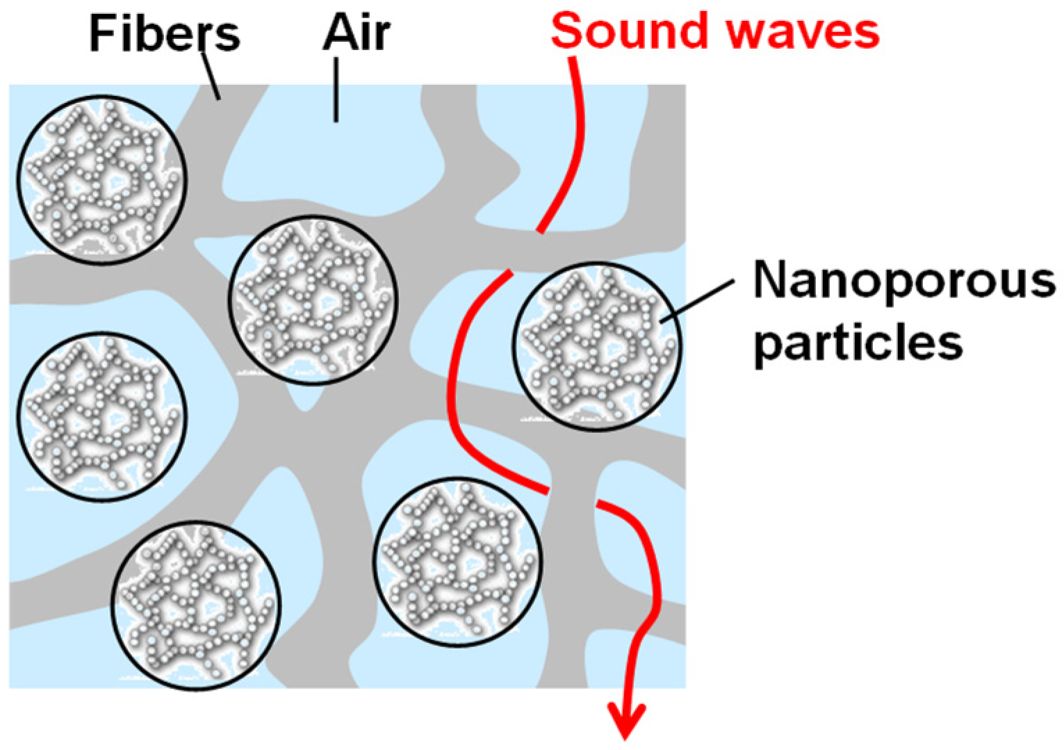
Figure 1. Structure of the devised porous material.
Applsci 14 05368 g001
Figure 2. Non-woven base sheet making equipment: (a) Sample Opener; (b) Sample Roller Card; (c) Prototype Powder Feeder.
Applsci 14 05368 g002
Figure 3. High-airflow-resistance surface material laminated to this porous material mat.
Applsci 14 05368 g003
Figure 4. Computational geometry: (a) non-woven fabric 1; (b) composite 1 (particle A mixed non-woven fabric); (c) composite 2 (particle B mixed non-woven fabric); (d) non-woven fabric 2.
Applsci 14 05368 g004
Figure 5. Spectra of predicted sound absorption coefficients of the computational geometry.
Applsci 14 05368 g005
Figure 6. Shape of mixed aerogel particles and tortuosity inside the porous material: (a) Spherical particles; (b) Elliptical flattened particles.
Applsci 14 05368 g006
Figure 7. External appearance of non-woven fabric: (a) polyethylene terephthalate (PET) non-woven fabric 1; (b) particle-mixed non-woven fabric; (c) Thinsulate.
Applsci 14 05368 g007
Figure 8. Distance between fibers of non-woven fabric and particle size distribution of mixed aerogel particles: (a) PET non-woven fabric 1; (b) particle-mixed non-woven fabric.
Applsci 14 05368 g008
Figure 9. Measured normal-incidence sound absorption coefficients of particle-mixed non-woven fabric.
Applsci 14 05368 g009
Figure 10. Measured normal-incidence sound absorption coefficients of particle-mixed non-woven fabric + skin material.
Applsci 14 05368 g010
Figure 11. Measured thermal conductivity of particle-mixed non-woven fabric + skin material.
Applsci 14 05368 g011
Table 1. Calculation conditions.
Fiber
Diameter
(μm)
Density of
Fiber
(g/cm3)
Density of
Particle
(g/cm3)
Bulk
Density
(kg/m3)
Particle
Content
(wt%)
Particle
Shape/pcs.
Center of
Gravity
(x,y,z)
Non-woven fabric 1
Figure 4a
101.38-13.8--/0-
Composite 1
Figure 4b
101.380.1516.819.5Particle A
/4
(250,500,500)
(750,500,500)
(500,500,250)
(500,500,750)
Composite 2
Figure 4c
101.380.1516.819.5Particle B
/4
(250,500,500)
(750,500,500)
(500,500,250)
(500,500,750)
Non-woven fabric 2
Figure 4d
101.38-16.7--/0-
Table 2. Average sound absorption coefficient predicted from calculations.
Title 1500–1600 Hz
Average
Sound Absorption
Coefficient
500–3150 Hz
Average
Sound Absorption
Coefficient
1000–5000 Hz
Average
Sound Absorption
Coefficient
Non-woven fabric 10.120.200.33
Composite 10.120.200.33
Composite 20.130.230.41
Non-woven fabric 20.120.210.36
Table 3. Properties of particle-mixed non-woven fabric.
Bulk Density of
Non-Woven Fabric
(kg/m3)
Thickness
(mm)
500–1600 Hz
Average
Sound Absorption
Coefficient
W/Skin Material
500–1600 Hz
Average
Sound Absorption
Coefficient
Airflow
Resistance
@0.5 mm/s
(Pa·s/m)
PET non-woven fabric 116.210.10.140.38102
PET non-woven fabric 2100.510.30.270.391500
Particle-mixed
non-woven fabric
87.210.00.330.431200
Thinsulate16.510.00.15--
Disclaimer/Publisher’s Note: The statements, opinions and data contained in all publications are solely those of the individual author(s) and contributor(s) and not of MDPI and/or the editor(s). MDPI and/or the editor(s) disclaim responsibility for any injury to people or property resulting from any ideas, methods, instructions or products referred to in the content.