
Sound-Absorbing, Thermal-Insulating Material Based on Non-Woven Fabrics Mixed with Aerogel Particles

Abstract
:Featured Application
Abstract
1. Introduction
2. Materials and Methods
2.1. Computational Microstructure Modeling Approach Applied to Porous Materials
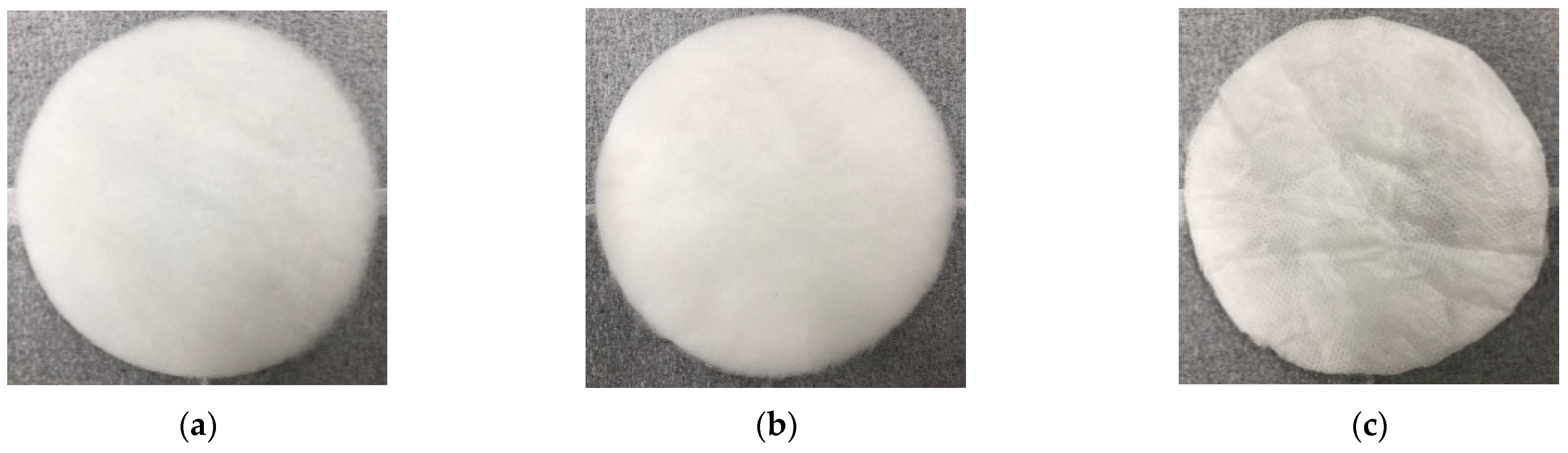
2.2. Preparation of Porous Materials and Performance Evaluation Methods
3. Results and Discussion
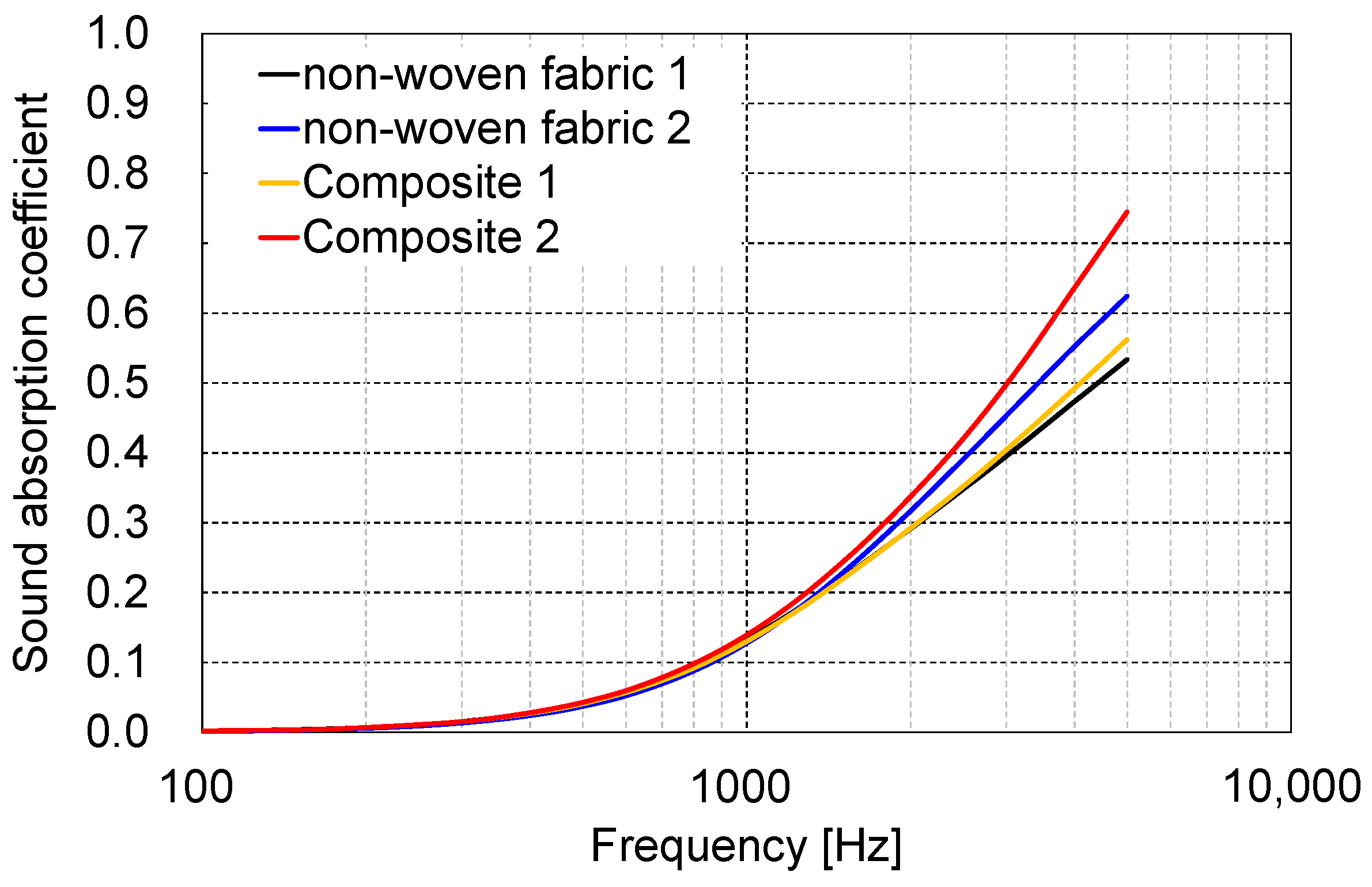
3.1. Prediction Calculation Result of Sound Absorption Coefficient
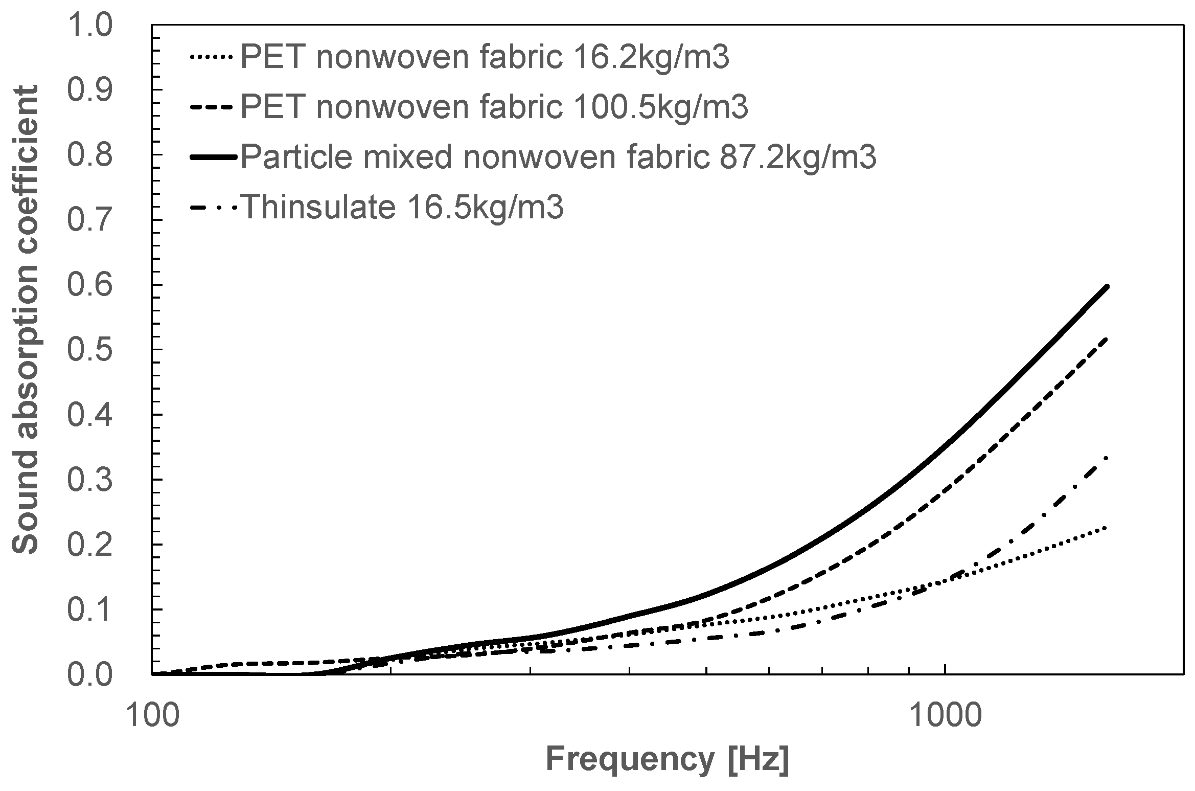
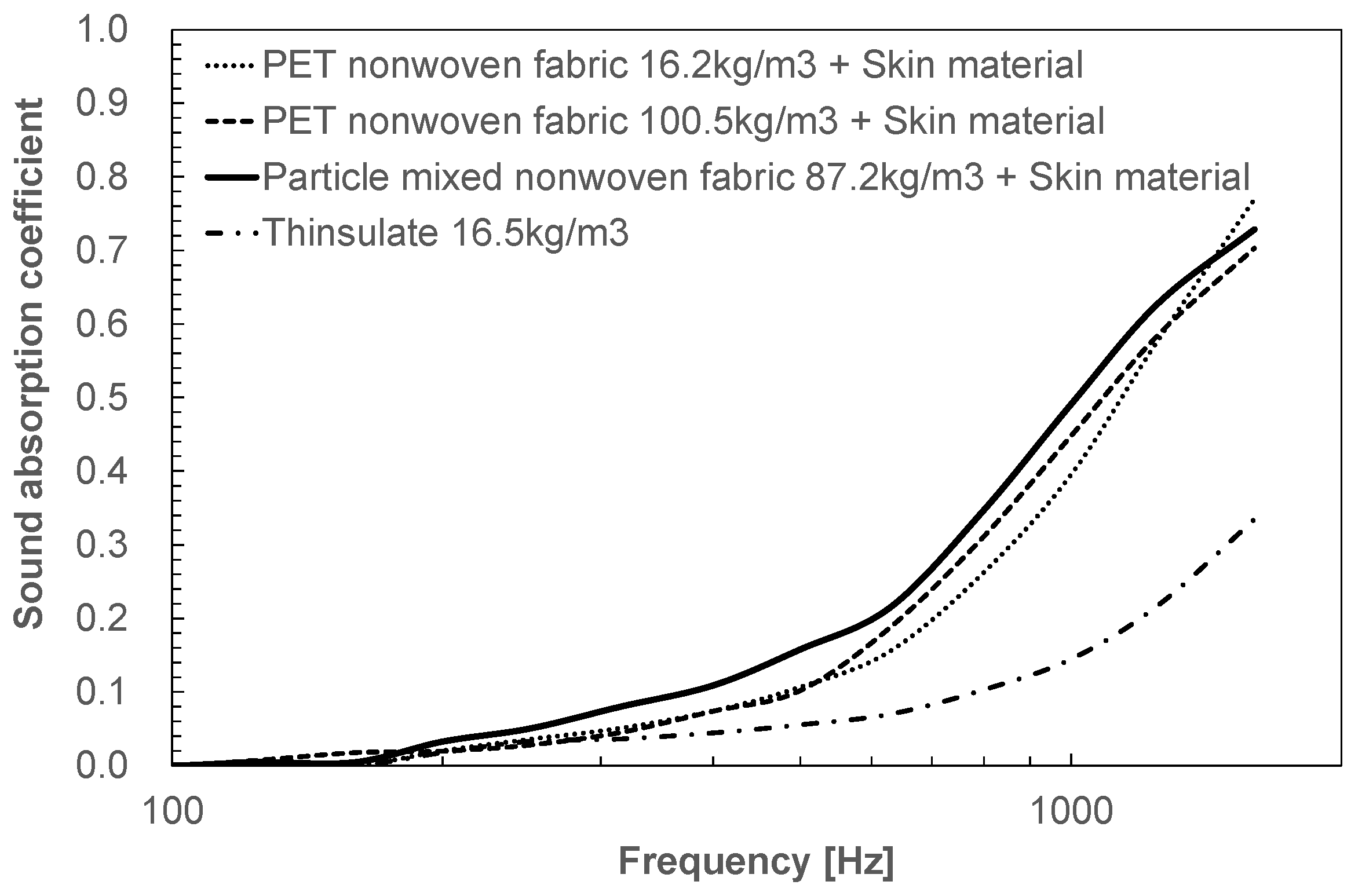
3.2. Performance Evaluation Result
4. Conclusions
Author Contributions
Funding
Institutional Review Board Statement
Informed Consent Statement
Data Availability Statement
Conflicts of Interest
References
- Shrestha, S.S.; Tiwari, J.; Rai, A.; Hun, D.E.; Howard, D.; Desjarlais, A.O.; Francoeur, M.; Feng, T. Solid and gas thermal conductivity models improvement and validation in various porous insulation materials. Int. J. Therm. Sci. 2023, 187, 108164. [Google Scholar] [CrossRef]
- Zhou, Y.; Huang, B.; Cao, B.-Y. Vibrational modes with long mean free path and large volumetric heat capacity drive higher thermal conductivity in amorphous zeolitic imidazolate Framework-4. Mater. Today Phys. 2021, 21, 100516. [Google Scholar] [CrossRef]
- Qiu, B.; Bao, H.; Zhang, G.; Wu, Y.; Ruan, X. Molecular dynamics simulations of lattice thermal conductivity and spectral phonon mean free path of PbTe: Bulk and nanostructures. Comput. Mater. Sci. 2012, 53, 278–285. [Google Scholar] [CrossRef]
- Gao, K.; van Dommelen, J.A.W.; Geers, M.G.D. Investigation of the effects of the microstructure on the sound absorption performance of polymer foams using a computational homogenization approach. Eur. J. Mech. A Solids 2017, 61, 330–344. [Google Scholar] [CrossRef]
- Gao, K.; van Dommelen, J.A.W.; Göransson, P.; Geers, M.G.D. A homogenization approach for characterization of the fluid–solid coupling parameters in Biot’s equations for acoustic poroelastic materials. J. Sound. Vib. 2015, 351, 251–267. [Google Scholar] [CrossRef]
- Zieliński, T.G. Microstructure-based calculations and experimental results for sound absorbing porous layers of randomly packed rigid spherical beads. J. Appl. Phys. 2014, 116. [Google Scholar] [CrossRef]
- Perrot, C.; Chevillotte, F.; Tan Hoang, M.; Bonnet, G.; Bécot, F.-X.; Gautron, L.; Duval, A. Microstructure, transport, and acoustic properties of open-cell foam samples: Experiments and three-dimensional numerical simulations. J. Appl. Phys. 2012, 111. [Google Scholar] [CrossRef]
- Lee, C.-Y.; Leamy, M.J.; Nadler, J.H. Frequency band structure and absorption predictions for multi-periodic acoustic composites. J. Sound. Vib. 2010, 329, 1809–1822. [Google Scholar] [CrossRef]
- Wu, C.M.; Chou, M.H. Polymorphism, piezoelectricity and sound absorption of electrospun PVDF membranes with and without carbon nanotubes. Compos. Sci. Technol. 2016, 127, 127–133. [Google Scholar] [CrossRef]
- Shen, L.; Zhang, H.; Lei, Y.; Chen, Y.; Liang, M.; Zou, H. Hierarchical pore structure based on cellulose nanofiber/melamine composite foam with enhanced sound absorption performance. Carbohydr. Polym. 2021, 255, 117405. [Google Scholar] [CrossRef]
- Zhao-Xuan, D.; Ying, W. Optimization and characterization of polyurethane electro-spun nano-membranes used for the surfaces of sound absorbent multi-layer sheets. J. Macromol. Sci. B 2021, 60, 647–662. [Google Scholar] [CrossRef]
- Neslihan, K.; Ilkay, O.Y.; Nuray, U.; Aysen, O.; Cafer, K. Sound absorption and thermal insulation properties of composite thermoplastic polyurethane/polystyrene (TPU/PS) nanofiber web and TPU nanofiber web and PS-extracted TPU/PS microfiber web. J. Ind. Text. 2022, 51, 7963S–7982S. [Google Scholar]
- Davoudabadi Farahani, M.; Jamshidi Avanaki, M.; Jeddi, A.A. Sound absorption of warp knitted spacer fabrics based on knit structure and nanofiber enhancement. J. Ind. Text. 2022, 51, 1539–1557. [Google Scholar] [CrossRef]
- Yan, P.; Zhou, B.; Du, A. Synthesis of polyimide cross-linked silica aerogels with good acoustic performance. RSC Adv. 2014, 4, 58252–58259. [Google Scholar] [CrossRef]
- Sachithanadam, M.; Joshi, S.C. Effect of granule sizes on acoustic properties of protein-based silica aerogel composites via novel inferential transmission loss method. Gels 2016, 2, 11. [Google Scholar] [CrossRef] [PubMed]
- Merli, F.; Anderson, A.M.; Carroll, M.K.; Buratti, C. Acoustic measurements on monolithic aerogel samples and application of the selected solutions to standard window systems. J. Appl. Acoust. 2018, 142, 123–131. [Google Scholar] [CrossRef]
- Oh, K.W.; Kim, D.K.; Kim, S.H. Ultra-porous flexible PET/Aerogel blanket for sound absorption and thermal insulation. Fibers Polym. 2009, 10, 731–737. [Google Scholar] [CrossRef]
- Küçük, M.; Korkmaz, Y. The effect of physical parameters on sound absorption properties of natural fiber mixed nonwoven composites. Text. Res. J. 2012, 82, 2043–2053. [Google Scholar] [CrossRef]
- Motahari, S.; Javadi, H.; Motahari, A. Silica-aerogel cotton composites as sound absorber. J. Mater. Civ. Eng. 2015, 27, 04014237. [Google Scholar] [CrossRef]
- Ramamoorthy, M.; Pisal, A.; Rengasamy, R.; Rao, A.V. In-situ synthesis of silica aerogel in polyethylene terephthalate fibre nonwovens and their composite properties on acoustical absorption behavior. J. Porous Mater. 2018, 25, 179–187. [Google Scholar] [CrossRef]
- Yang, T.; Xiong, X.; Venkataraman, M.; Mishra, R.; Nov, J.; Militký, J. Investigation on sound absorption properties of aerogel/polymer nonwovens. J. Text. I 2019, 110, 196–201. [Google Scholar] [CrossRef]
- Talebi, Z.; Soltani, P.; Habibi, N.; Latifi, F. Silica aerogel/polyester blankets for efficient sound absorption in buildings. Constr. Build. Mater. 2019, 220, 76–89. [Google Scholar] [CrossRef]
- Mazrouei-Sebdani, Z.; Begum, H.; Schoenwald, S.; Horoshenkov, K.V.; Malfait, W.J. A review on silica aerogel-based materials for acoustic applications. J. Non-Crystal Solids 2021, 562, 120770. [Google Scholar] [CrossRef]
- Katsura, D.; Yamamoto, T.; Yamakawa, K.; Hatakeyama, N.; Miura, R.; Okajima, J.; Inaba, K.; Ishizawa, Y.; Ochiai, H.; Yukawa, H.; et al. Development of Thermal Management and Noise/Vibration Control Material Model Technology by Model-Based Research (MBR); 1st Report JSAE Annual Congress (Spring) Proceedings, 2021; p. 20215301. Available online: https://tech.jsae.or.jp/paperinfo/en/content/p202101.301/ (accessed on 10 May 2024).
- Katsura, D.; Maeda, T.; Kanamori, K.; Yamamoto, T.; Ohshita, J. Sound-absorbing, thermal-insulating material based on poly(methylsiloxane) xerogel and cellulose nanofibers. Appl. Sci. 2024, 14, 2570. [Google Scholar] [CrossRef]
- Katsura, D.; Yamakawa, K. Development of Flow Resistance Control Technology for Sound Absorbing Material Surface by Model-Based Research (MBR); JSAE Annual Congress (Spring) Proceedings, 2023; p. 20235296. Available online: https://tech.jsae.or.jp/paperinfo/ja/content/p202301.296/ (accessed on 10 May 2024).
- ISO 10534-2:2023; Acoustics—Determination of Acoustic Properties in Impedance Tubes—Part 2: Two-Microphone Technique for Normal Sound Absorption Coefficient and Normal Surface Impedance. International Organization for Standardization: Geneva, Switzerland, 2023.
- ISO 9053-1:2018; Acoustics—Determination of Airflow Resistance—Part 1: Static Airflow Method. International Organization for Standardization: Geneva, Switzerland, 2018.
- ISO 8301:1991; Thermal Insulation—Determination of Steady-State Thermal Resistance and Related Properties—Heat Flow Meter Apparatus. International Organization for Standardization: Geneva, Switzerland, 1991.


| Fiber Diameter (μm) | Density of Fiber (g/cm3) | Density of Particle (g/cm3) | Bulk Density (kg/m3) | Particle Content (wt%) | Particle Shape/pcs. | Center of Gravity (x,y,z) | |
|---|---|---|---|---|---|---|---|
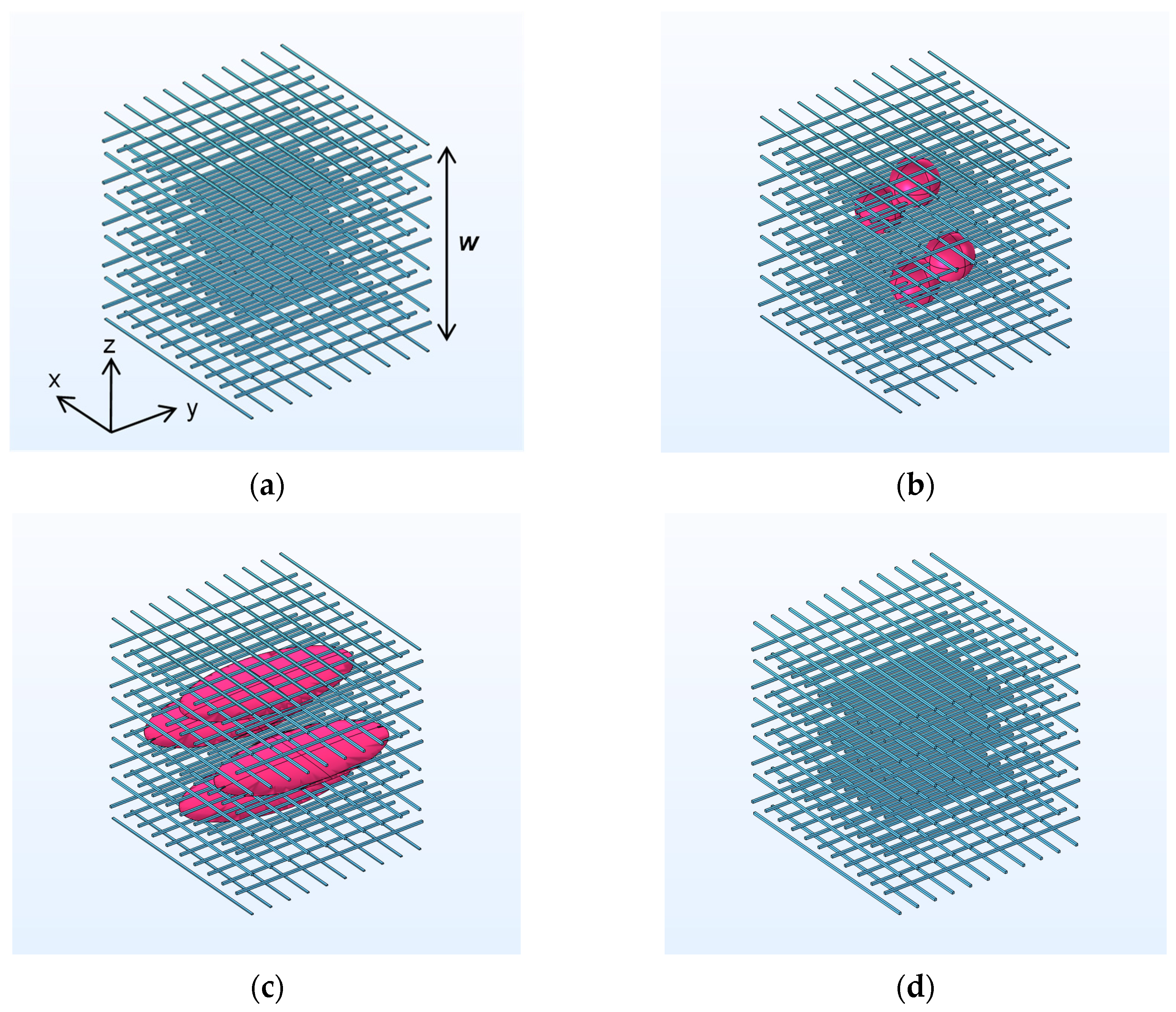
| Non-woven fabric 1 Figure 4a | 10 | 1.38 | - | 13.8 | - | -/0 | - |
| Composite 1 Figure 4b | 10 | 1.38 | 0.15 | 16.8 | 19.5 | Particle A /4 | (250,500,500) (750,500,500) (500,500,250) (500,500,750) |
| Composite 2 Figure 4c | 10 | 1.38 | 0.15 | 16.8 | 19.5 | Particle B /4 | (250,500,500) (750,500,500) (500,500,250) (500,500,750) |
| Non-woven fabric 2 Figure 4d | 10 | 1.38 | - | 16.7 | - | -/0 | - |
| Title 1 | 500–1600 Hz Average Sound Absorption Coefficient | 500–3150 Hz Average Sound Absorption Coefficient | 1000–5000 Hz Average Sound Absorption Coefficient |
|---|---|---|---|
| Non-woven fabric 1 | 0.12 | 0.20 | 0.33 |
| Composite 1 | 0.12 | 0.20 | 0.33 |
| Composite 2 | 0.13 | 0.23 | 0.41 |
| Non-woven fabric 2 | 0.12 | 0.21 | 0.36 |
| Bulk Density of Non-Woven Fabric (kg/m3) | Thickness (mm) | 500–1600 Hz Average Sound Absorption Coefficient | W/Skin Material 500–1600 Hz Average Sound Absorption Coefficient | Airflow Resistance @0.5 mm/s (Pa·s/m) | |
|---|---|---|---|---|---|
| PET non-woven fabric 1 | 16.2 | 10.1 | 0.14 | 0.38 | 102 |
| PET non-woven fabric 2 | 100.5 | 10.3 | 0.27 | 0.39 | 1500 |
| Particle-mixed non-woven fabric | 87.2 | 10.0 | 0.33 | 0.43 | 1200 |
| Thinsulate | 16.5 | 10.0 | 0.15 | - | - |
Disclaimer/Publisher’s Note: The statements, opinions and data contained in all publications are solely those of the individual author(s) and contributor(s) and not of MDPI and/or the editor(s). MDPI and/or the editor(s) disclaim responsibility for any injury to people or property resulting from any ideas, methods, instructions or products referred to in the content. |
© 2024 by the authors. Licensee MDPI, Basel, Switzerland. This article is an open access article distributed under the terms and conditions of the Creative Commons Attribution (CC BY) license (https://creativecommons.org/licenses/by/4.0/).
Share and Cite
Katsura, D.; Ochiai, H.; Kawabe, M.; Yamamoto, T.; Ohshita, J. Sound-Absorbing, Thermal-Insulating Material Based on Non-Woven Fabrics Mixed with Aerogel Particles. Appl. Sci. 2024, 14, 5368. https://doi.org/10.3390/app14135368
Katsura D, Ochiai H, Kawabe M, Yamamoto T, Ohshita J. Sound-Absorbing, Thermal-Insulating Material Based on Non-Woven Fabrics Mixed with Aerogel Particles. Applied Sciences. 2024; 14(13):5368. https://doi.org/10.3390/app14135368
Chicago/Turabian StyleKatsura, Daiji, Hiroya Ochiai, Mitsuyoshi Kawabe, Takashi Yamamoto, and Joji Ohshita. 2024. "Sound-Absorbing, Thermal-Insulating Material Based on Non-Woven Fabrics Mixed with Aerogel Particles" Applied Sciences 14, no. 13: 5368. https://doi.org/10.3390/app14135368