Abstract
Space cameras play a pivotal role in various fields, such as astronomical exploration. When operating in orbit, these cameras encounter the relative motion between the target and the camera during the exposure, resulting in image motion, which affects the imaging quality. Therefore, it is necessary to compensate for this image motion. This paper investigates the in-orbit image motion compensation (IMC) method for space cameras with a long integration time based on a two-axis pointing platform. Firstly, the mechanical design of the camera is introduced. Secondly, the in-orbit IMC model for the camera is analyzed, and the angular motion needed for compensating for the image motion by the two-axis pointing platform are derived. Factors influencing the compensation accuracy are also analyzed. The effectiveness of the IMC model is verified through simulations. Finally, the in-orbit experimental results indicate that the energy concentration of the target star images obtained exceeded 70%, demonstrating excellent performance in space cameras and effectively enhancing imaging quality using IMC technology.
1. Introduction
Space cameras play a crucial role in various fields, such as Earth observation and astronomical exploration, due to their advantages of being less affected by atmospheric disturbances and not being limited by geographical locations [1,2,3]. With the increasing demand for detecting faint celestial objects in space, cameras often require a longer integration time. Space cameras mounted on satellites face challenges when taking photographs due to the orbital motion and attitude motion of the satellite. During the integration time, there is a relative motion between the target and the camera that results in image blur. Therefore, the image motion compensation (IMC) technique is needed to enhance image clarity and resolution [4,5]. This is particularly true for cameras that require long integration times to capture faint and weak targets. The commonly used methods for IMC include the optical IMC method, the image-based IMC method, and the mechanical IMC method.
Optical IMC methods involve rotating or moving optical components in the optical path to change the direction of light and to compensate for image motion in accordance with the principle of matching the image motion speed on the camera focal plane [6]. A common approach is to compensate for forward image motion by rotating a reflecting mirror that is located in front of the objective lens. In [7], a novel IMC method was proposed to compensate for both image rotation and image translation simultaneously using a scan mirror. In [8], a two-axis, fast steering mirror was designed for aerial dynamic scans and a stare imaging system. The effectiveness of the fast steering mirror and IMC algorithm was verified by the dynamic imaging test in the laboratory and flight tests. Through adopting the optical IMC method, the mirror-reflected optical paths faced issues such as inconsistency between the center and the edges of the field of view, deviations in the optical axis, and even defocusing caused by compensation. It was challenging to completely eliminate the image motion in the resulting images.
Another approach is to compensate for image motion through digital image processing algorithms. These algorithms, such as image registration and motion estimation, are used to correct the image motion and motion blur in the captured images [9]. In [10], an improved Wiener filtering algorithm was proposed to restore the blurred image. Experimental results showed that the absolute average error of the image for improved algorithms decreased by 9.31%, and the peak signal-to-noise ratio increased by 13.98% when compared to the traditional Wiener filter method. Ref. [11] proposed a blind image restoration method using the Huber–Markov prior model to both regularize the image and the blur parameters. Experiments were performed to demonstrate the effectiveness of the proposed approach. Ref. [12] proposed a new blind deblurring learning framework that utilizes alternating iterations of shrinkage thresholds, and they proposed a learnable blur kernel proximal mapping module to improve the accuracy of blur kernel reconstructions. The experiments demonstrated that the proposed framework yields superior image restoration quality for blurred images with varying levels of deterioration. However, due to the blurring during the imaging process, some of the information in the image may have been lost, resulting in limited compensation accuracy through digital image processing algorithms.
The mechanical IMC method utilizes a mechanical structure to move the camera in the direction of the image motion during exposure [13,14]. The compensation speed for each point on the image plane was consistent, enabling two-axis compensation. This method is commonly used in ground or airborne cameras, but less frequently employed in space cameras. In space cameras, two-axis pointing platforms are often used to increase the pointing range, but they are rarely used to compensate for image motion [15].
Due to the limitations of optical systems and the need for detecting faint and weak star point targets, optical- or image-based IMC methods cannot be used. Therefore, a mechanical IMC method was designed to compensate for the image motion in long-integration space cameras using a two-axis pointing platform.
The rest of this paper is structured as follows: Section 2 provides a detailed description of the mechanical design of the camera. Section 3 analyzes the image motion of the camera in orbit using homogeneous coordinate transformations, as well as calculates the required compensation angles for the two-axis pointing platform. At the same time, an analysis of the factors that affect the accuracy of IMC is also conducted. In Section 4, the simulation analysis demonstrates that images without IMC exhibit trailing effects after imaging, while images with IMC achieve ideal imaging results. Section 5 presents the imaging results obtained in orbit. Section 6 concludes the paper.
2. Mechanism Description
A structure diagram of a space camera with a two-axis pointing platform is given in Figure 1. The platform consists of two axes, namely the elevation axis and azimuth axis. The two axes are orthogonal and rotate independently, allowing for the simultaneous adjustment of imaging directions. The base is installed on the spacecraft. The azimuth mechanism is assembled on the elevation mechanism, and the camera is assembled on the azimuth mechanism. When the elevation axis rotates, the azimuth axis will rotate accordingly. The rotation range of the elevation axis is to , and the rotation range of the azimuth axis is to . A large rotation range ensures that the camera can capture targets that require a large angle of rotation, thus increasing the detection range. Meanwhile, the camera achieves IMC through the rotation of the two-axis pointing platform. The setting of the rotation range can include the entire stroke needing rotation by the IMC.
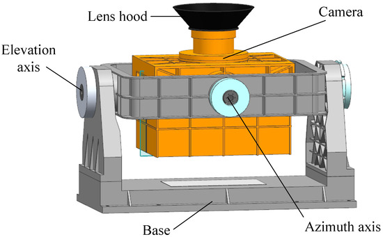
Figure 1.
Structure diagram of a space camera with a two-axis pointing platform.
Permanent magnet torque motors were used to drive the shaft of each axis directly, which eliminate transmission clearance and guarantee rotation accuracy. High-precision encoders were installed on the shaft for the real-time acquisition of the mechanism rotation angle. The direct drive mechanism improves structural stiffness and accordingly increases the closed-loop bandwidth of the servo system.
During the in-orbit imaging period, the IMC calculation module calculates the pointing platform guidance position in real time, guiding the platform to rotate (this will be discussed in the next section).
3. Model of Image Motion
3.1. Coordinate Systems
In the process of transforming the coordinate systems from object remote sensors to optical remote sensors in a space camera, the right-hand Cartesian coordinate systems was adopted. Using homogeneous coordinate transformation matrices is a convenient method for expressing coordinate transformations. The position relationship between each coordinate system is shown in Figure 2. The coordinate systems involved in mapping from the object to the image plane are defined in the following section.
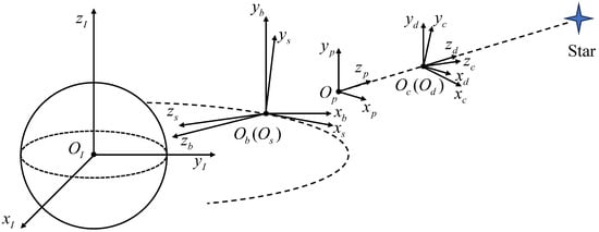
Figure 2.
Imaging coordinate system of a space camera.
- 1.
- Geocentric inertial coordinate system : The origin is geocentric, points to the intersection of the orbital plane and the equatorial plane, points to the north pole, is perpendicular to and , and the coordinate system maintains the inertial space.
- 2.
- Spacecraft orbit coordinate system : The origin is in orbit, with the pointing forward along the orbit and the pointing toward space. It also passes through the origin of the geocentric inertial coordinate system. The and axes are located within the track plane, while the axis is perpendicular to the track plane. The spacecraft orbit coordinates are located in the geocentric inertial coordinate system and move in orbit at an angular velocity .
- 3.
- Spacecraft coordinate system : The origin is the same as the origin of the spacecraft orbit coordinate system. When the spacecraft is stationary without motion, the spacecraft coordinate system coincides with the spacecraft orbit coordinate system . When the spacecraft has an attitude motion, the spacecraft coordinate system can be obtained by rotating the spacecraft orbit coordinate system. The roll angle is , the pitch angle is , and the yaw angle is .
- 4.
- Camera installation coordinate system : The origin of the camera installation coordinate system is the main point of the camera objective. When the error between the camera and the spacecraft is within the installation allowable range, the camera installation coordinate system completely coincides with the spacecraft coordinate system.
- 5.
- Camera object plane coordinate system : The origin is located at the object main point of the camera. The plane is the object principal plane of the camera, and the axis is the optical axis direction, forming the right-hand coordinate system. When the positioning star is located on the optical axis, the camera object coordinate system coincides with the camera installation coordinate system. If the positioning star is not on the optical axis, the camera needs to rotate the two-axis pointing platform to make the positioning star on the optical axis. The camera object plane coordinate system can be obtained by rotating the camera installation coordinate system. The azimuth angle of the turntable is , and the elevation angle is .
- 6.
- Camera image plane coordinate system : The origin is the main point of the image plane. The plane is the main plane of the image plane of the camera, and the axis points toward the direction of the imaging element integration sequence and is parallel to the axis . The axis is the normal direction of the main plane of the image plane. For coaxial optical systems, the normal direction of the image plane is the same as the optical axis direction, so the axis and axis directions are the same, forming a right-hand coordinate system.
Following the procedures shown in Figure 3, the coordinate transformation from the geocentric inertial coordinate system to the camera image plane coordinate system can be given as follows.
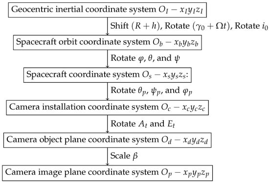
Figure 3.
The coordinate transformations’ detailed operations.
- 1.
- Geocentric inertial coordinate system to spacecraft orbit coordinate system :The spacecraft orbital coordinate system is obtained by the geocentric inertial coordinate system after translation and then rotation, where is the initial orbit angle, is the orbital angular velocity, is the orbit inclination angle, R is the Earth radius, and h is the orbit height. Therefore, the transformation matrix between the two coordinate systems at time t can be expressed as
- 2.
- Spacecraft orbit coordinate system to spacecraft coordinate system :The spacecraft orbital coordinate system is sequentially transformed into the spacecraft coordinate system through a rotation of the roll angle , pitch angle , and yaw angle . The transformation matrix can be expressed as follows:
- 3.
- Spacecraft coordinate system to camera installation coordinate system :The installation angle errors in the pitch, yaw, and roll directions are , , and , respectively. The transformation matrix is as follows:
- 4.
- Camera installation coordinate system to camera object plane coordinate system :The camera object plane coordinate system is obtained by rotating the camera installation coordinate system . The azimuth angle of the turntable is , and the elevation angle is . The transformation matrix is
- 5.
- Camera object plane coordinate system to camera image plane coordinate system :The matrix transformation is related to the action matrix of optical components. Assuming the focal length of the object and the image are f and , respectively, the lateral magnification of the optical systems is , and the transformation matrix can be expressed as follows:The coordinate transformation matrix from the geocentric inertial coordinate system to the object plane coordinate system is
Supposing the right ascension and declination coordinates of the target star are , then the homogeneous coordinates of the unit vector of the star’s direction in the geocentric inertial coordinate system are
During the exposure time, the image of the target star is always maintained at the center of the image plane through the motion of a two-axis pointing platform, and the coordinates of the image in the camera image coordinate system are
Given the satellite orbital motion parameters, satellite attitude parameters, and camera installation matrix, as well as by guaranteeing the matching of objects and images during in-orbit exposure by transforming the matrix , the following equation is satisfied
where the azimuth and the elevation angle of the two-axis pointing platform and can be obtained.
3.2. Analysis of In-Orbit Disturbances
During the imaging process in space, a space camera is subjected to various sources of disturbances. These disturbances not only affect the spacecraft’s attitude, but also impact the control precision of the pointing platform. As a result, the accuracy of the image motion compensation by the camera is compromised, thereby affecting the quality of the captured images. In light of these challenges, the following analysis can be made:
3.2.1. Disturbances of Spacecraft
A spacecraft in space is subject to various sources of disturbances, including but not limited to the following:
- 1.
- Attitude control system: The operation of the attitude control system may introduce internal feedback disturbances, such as vibrations or noise in control signals. These disturbances can negatively impact the stability of the spacecraft’s attitude.
- 2.
- Solar radiation pressure: Solar radiation exerts pressure on the spacecraft’s surface, thus generating small forces that can induce attitude changes.
- 3.
- Gyroscope drift: Gyroscopes on the spacecraft may experience drift, thus leading to errors in attitude measurement and affecting the precision of the stable platform.
These dynamic disturbances can influence the spacecraft’s attitude, thereby impacting the accuracy of camera image motion compensation and ultimately affecting the image quality. To mitigate these disturbances, the corresponding compensation angles are calculated based on the real-time monitoring of satellite attitude parameters in the IMC model.
3.2.2. The Disturbances of a Pointing Platform
The pointing platform, which is driven by a permanent magnet synchronous motor in orbit, is subject to various sources of disturbances, including the following:
- 1.
- Transition from a gravity environment to microgravity environment: The transition from a gravity environment on the ground to a microgravity environment in space involves a release of gravity. This can cause structural deformations as the structure adapts to the absence of gravity, resulting in changes in the friction forces between the motor shaft and the structure. These changes in friction forces can impact control precision.
- 2.
- Temperature variations: In a space environment, there are significant temperature variations. These variations can cause changes in the magnetic materials and coil parameters inside the motor, thereby affecting the motor’s output characteristics and control performance.
- 3.
- Radiation and electromagnetic interference: The presence of radiation and electromagnetic interference around the spacecraft can interfere with the control circuits and sensors of the motor, leading to fluctuations in torque and speed.
To overcome these disturbances, the motor design and material selection can be optimized to enhance the motor’s resistance to magnetic field interference and temperature adaptability. Additionally, it is essential to design more robust control algorithms to improve the precision of pointing platform tracking control, which will be introduced in the next subsection.
In general, the disturbances of a spacecraft affect the accuracy of satellite attitude and orbit parameters h, , , and , which will reduce the accuracy of IMC calculations and reduce imaging quality. At the same time, the disturbances of a pointing platform will affect the pointing accuracy of said pointing platform, i.e., and , which will reduce the compensation accuracy and affect the imaging accuracy.
3.3. Disturbances Rejection Strategy
Disturbances affecting satellites can ultimately impact the accuracy of their orbital and attitude parameters. By enhancing the measurement precision of these parameters, it is possible to effectively mitigate the influence on the accuracy of IMC.
For the disturbances affecting a pointing platform, a disturbance rejection control strategy is employed to enhance the disturbance rejection performance. The pointing platform utilizes a three-loop control method involving current, velocity, and position. The current loop employs PI control, with a linear control design that features a sufficiently high bandwidth to ensure a rapid response speed for the current. Within a velocity loop, sliding mode control (SMC) is used to improve the system’s ability to reject disturbances and enhance the dynamic response performance of the system. The position loop control ensures the tracking accuracy of the system. The specific controller design for the velocity loop is as follows:
The mechanical motion of the permanent magnet torque motor is described by
where J is the mechanical inertia of the motor and load, B is the coefficient of viscous friction, d is the load disturbance, and is the torque constant.
Setting as the reference speed, the speed error can be defined as
We can define the sliding surface as
where c is a positive constant.
A sliding mode controller with the exponential reaching law can be designed as
where are positive constants.
The stability proof of the controller can be found in [16].
The block diagram of the imaging control is shown in Figure 4. The camera first receives the orbit and attitude information of the satellite, as well as the position of the target star. Based on the above information, it performs IMC calculations and calculates the angle and that need to be compensated for pointing to the two-axis of the platform. The pointing platform achieves a high-precision, three loop control based on and , thereby realizing a high-precision pointing of the platform and controlling the camera rotation.
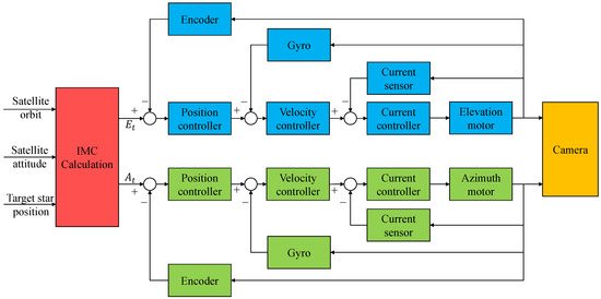
Figure 4.
Block diagram of the imaging control.
4. Simulation
In this section, the imaging by a space camera is simulated and analyzed. The center of the field of view is aligned with the target star when the pointing platform is at the initial angle of 0. As the satellite moves along its orbit and undergoes attitude variations, the pointing platform maintains the target star at the center of the field of view during a six-second integration time by compensating for image motion using the IMC model. The satellite operates in a low Earth orbit: the orbit height h is 400 km and the earth radius R is 6400 km. The satellite’s attitude changes, caused by disturbance factors, are also taken into consideration. At 3 s, a disturbance of adding 100 arcseconds to the satellite’s three-axis attitude angles is introduced. The sampling frequency of the simulation is 200 Hz. After calculating the IMC model, the two-axis reference position, actual position, and the position tracking errors of the pointing platform were determined, as shown in Figure 5 and Figure 6, with the azimuth axis in Figure 5 and the elevation axis in Figure 6, respectively. The pointing platform was able to achieve high control accuracy and ensured compensation for the image motion.
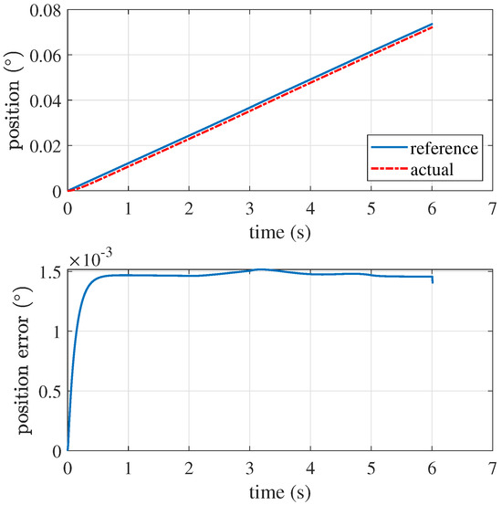
Figure 5.
Position tracking and error of the azimuth angle.
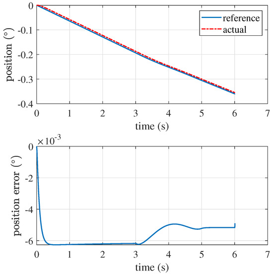
Figure 6.
Position tracking and error of the elevation angle.
In using ideal point-source imaging, multiple image points within the exposure time were accumulated and displayed on the image plane. The optical coordinates of the stars within a 4 × 4 degree field of view on the image plane, without compensation for image motion and post-image motion compensation using the pointing platform, are shown in Figure 7 and Figure 8, respectively. From the figures, it can be observed that, after applying IMC, the camera produces star-like points, which closely resemble the ideal point sources. In contrast, when the camera does not utilize IMC, there is significant trailing observed in the images, thus rendering them ineffective for accurate observations of celestial objects.
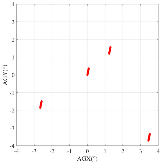
Figure 7.
Image without IMC.
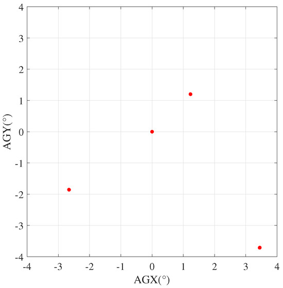
Figure 8.
Image with IMC.
5. In-Orbit Verification
In this section, the in-orbit experimental results are presented. The satellite operates in a low-earth orbit, with the orbit height h being 400 km. The camera utilizes a CMOS imaging sensor with a pixel size of 5.5 μm. The orbit and attitude information of the satellite is sent in real time to the camera to calculate the compensated image motion. Figure 9 presents two typical in-orbit images of stars that were captured using the IMC technique with the local area of the target star and gray-scale three-dimensional images of the corresponding image data. From the figure, it is evident that the imaging results were excellent after compensating for image motion through the pointing platform. The energy concentrations of 5 × 5 pixels in Figure 9a,b are 71.8% and 73.4%, respectively. The calculation method of energy concentration is given in (14), where represents the DN value of a pixel. The energy concentration of the target stars in the overall captured images exceeds 70%, thus meeting the requirements for detecting high-magnitude celestial targets. As it is generated after the image motion compensated, the image is representative enough to illustrate the IMC method using the two-axis pointing platform for space cameras.
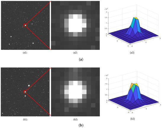
Figure 9.
Images of the star targets captured by cameras in orbit. (a1,b1): Original image captured by camera; (a2,b2): local area of the target star; (a3,b3): gray-scale three-dimensional images of the corresponding image data.
6. Conclusions
This paper proposes the utilization of a two-axis pointing platform to achieve IMC for long-exposure space cameras. By employing homogeneous coordinate transformation, the image motion model was derived, and the required compensating pointing angles for the two-axis pointing platform were calculated. Factors that affect the precision of IMC were also analyzed. The effectiveness of IMC was verified through simulation results. In-orbit experimental results further validated the effectiveness of the proposed method, which effectively enhances the detection capability of faint stellar objects. This provides a feasible design for future in-orbit space camera studies with a long integration time.
In the future, we will enhance the imaging quality from two aspects based on IMC technology. On the one hand, will achieve this by employing more advanced sensor fusion techniques to improve the measurement accuracy of satellites, thereby enhancing the computational precision of IMC. On the other hand, we are also committed to developing advanced control algorithms and designing more sophisticated control algorithms, such as adaptive control methods and neural network approaches, to make the compensation more accurate. These strategic enhancements will be pivotal in achieving superior imaging performance, and they will also be integrated into our future work to further bolster the efficacy of our imaging systems.
Author Contributions
Conceptualization, X.C. and C.H.; methodology, X.C. and C.H.; software, X.Q.; validation, Z.M., W.L. and H.N.; formal analysis, X.C.; investigation, X.C.; resources, X.C.; data curation, X.C. and C.H.; writing—original draft preparation, X.C.; writing—review and editing, X.C. and C.H.; visualization, X.C.; supervision, X.C.; project administration, C.Y.; funding acquisition, C.Y. All authors have read and agreed to the published version of the manuscript.
Funding
This research was funded by the National Natural Science Foundation of China (grant number 12103053).
Institutional Review Board Statement
Not applicable.
Informed Consent Statement
Not applicable.
Data Availability Statement
The raw data supporting the conclusions of this article will be made available by the corresponding authors on request.
Acknowledgments
We wish to give our thanks to all the Project team members.
Conflicts of Interest
The authors declare no conflicts of interest.
Abbreviations
- The following abbreviations are used in this manuscript:
| IMC | Image Motion Compensation |
| DOAJ | Directory of open-access journals |
| TLA | Three letter acronym |
| LD | Linear dichroism |
References
- Zhang, G.; Zhao, H.; Zhang, G.; Chen, Y. Improved genetic algorithm for intrinsic parameters estimation of on-orbit space cameras. Opt. Commun. 2020, 475, 126235. [Google Scholar] [CrossRef]
- Gu, Y.; Shen, X.; He, G. MTF estimation via BP neural networks and Markov model for space optical camera. J. Frankl. Inst. 2013, 350, 3100. [Google Scholar] [CrossRef]
- Zhao, H.; Fan, X.; Zou, G. All-reflective optical bifocal zooming system without moving elements based on deformable mirror for space camera application. Appl. Opt. 2013, 52, 1192. [Google Scholar] [CrossRef] [PubMed]
- Wang, J.; Yu, P.; Yan, C.; Ren, J.; He, B. Space optical remote sensor image motion velocity vector computational modeling, error budget and synthesis. Chin. Opt. Lett. 2005, 3, 414–417. [Google Scholar]
- Sreekanth, R.V.; Ravinder, K.B.; Sridharan, R. Development of image motion compensation system for 1.3 m telescope at Vainu Bappu Observatory. Res. Astron. Astrophys. 2020, 20, 1. [Google Scholar]
- Wang, Y.; Tian, D. Review of image shift and image rotation compensation control technology for aviation optoelectronic imaging. Opt. Precis. Eng. 2022, 11, 3128. [Google Scholar] [CrossRef]
- Tian, D.; Wang, Y.; Wang, Z. Long Integral Time Continuous Panorama Scanning Imaging Based on Bilateral Control with Image Motion Compensation. Remote Sens. 2019, 11, 1924. [Google Scholar] [CrossRef]
- Sun, J.; Ding, Y.; Zhang, H.; Yuan, G.; Zheng, Y. Conceptual Design and Image Motion Compensation Rate Analysis of Two-Axis Fast Steering Mirror for Dynamic Scan and Stare Imaging System. Sensors 2021, 21, 6441. [Google Scholar] [CrossRef] [PubMed]
- Xu, J.; Jiang, M.; Yu, L. Robust Motion Compensation for Event Cameras with Smooth Constraint. IEEE Trans. Comput. Imaging 2020, 6, 604. [Google Scholar] [CrossRef]
- Cao, H.; Bayaiheshig; Cui, J.; Zhang, Y. Forward image motion compensation of hyper spectral image based on image restoration. Chin. Opt. 2013, 6, 856. [Google Scholar]
- Shen, H.; Du, L.; Zhang, L.; Gong, W. A Blind Restoration Method for Remote Sensing Images. IEEE Geosci. Remote Sens. Lett. 2012, 9, 6. [Google Scholar] [CrossRef]
- Feng, Y.; Yang, Y.; Fan, X.; Zhang, Z.; Zhang, J. A Multiscale Generalized Shrinkage Threshold Network for Image Blind Deblurring in Remote Sensing. IEEE Geosci. Remote Sens. Lett. 2024, 62, 5611316. [Google Scholar] [CrossRef]
- Yang, Y.; Yu, C.; Wang, Y. Imaging Attitude Control and Image Motion Compensation Residual Analysis Based on a Three-Axis Inertially Stabilized Platform. Appl. Sci. 2021, 11, 5856. [Google Scholar] [CrossRef]
- Xiu, J.; Huang, P.; Zhang, H. Line of Sight and Image Motion Compensation for Step and Stare Imaging System. Appl. Sci. 2020, 10, 7119. [Google Scholar] [CrossRef]
- Chen, B.; Zhang, X.; He, L. Solar X-ray and EUV imager on board the FY-3E satellite. Light. Sci. 2022, 11, 329. [Google Scholar] [CrossRef] [PubMed]
- Che, X.; Tian, D.; Jia, P. Cascade Terminal Sliding Mode Control for PMSM with Nonlinear Disturbance Observer. In Proceedings of the 2021 IEEE International Conference on Mechatronics (ICM), Kashiwa, Japan, 7–9 March 2021. [Google Scholar]
Disclaimer/Publisher’s Note: The statements, opinions and data contained in all publications are solely those of the individual author(s) and contributor(s) and not of MDPI and/or the editor(s). MDPI and/or the editor(s) disclaim responsibility for any injury to people or property resulting from any ideas, methods, instructions or products referred to in the content. |
© 2024 by the authors. Licensee MDPI, Basel, Switzerland. This article is an open access article distributed under the terms and conditions of the Creative Commons Attribution (CC BY) license (https://creativecommons.org/licenses/by/4.0/).