Article

Study on Field Test of Deformation and Stability Control Technology for Shallow Unsymmetrical Loading Section of Super-Large-Span Tunnel Portal

1
School of Highway, Chang’an University, Middle Section of Nan Erhuan Road, Xi’an 710064, China
2
Shandong Provincial Communications Planning and Design Institute Group Co., Ltd., No.576, Wuyingshanxi Road, Tianqiao District, Jinan 250031, China
*
Authors to whom correspondence should be addressed.
Appl. Sci. 2024, 14(13), 5796; https://doi.org/10.3390/app14135796
Submission received: 13 May 2024 / Revised: 28 June 2024 / Accepted: 29 June 2024 / Published: 2 July 2024
(This article belongs to the Special Issue Tunnel and Underground Engineering: Recent Advances and Challenges)

Abstract

:
This study focuses on monitoring the deformation of the shallow unsymmetrical section of a super-large-span tunnel portal relying on the newly built Shimentangshan Tunnel, and through numerical simulations, the construction sequence and drift ratios were optimized to address challenges related to the stability of surrounding rock and structure. The findings indicate that employing the double-side drift method results in a maximum settlement value of 107.0 mm and a maximum convergence value of 108.8 mm, leading to larger deformations. Excavating the shallow buried side first followed by the deep buried side proves beneficial for deformation control of the support structure and effectively limits damage to the surrounding rock. A drift ratio of 0.3 ensures optimal support structure security and stability. Considering both structural deformation and surrounding rock damage, a ratio between 0.25 and 0.35 for the drifts is recommended. Taking into account construction efficiency and economic benefits, a construction plan for the shallow buried unsymmetrical section at the portal of super-large-span tunnels is proposed.

1. Introduction

The construction of large-span tunnels is necessary to meet the growing demand for transport in China. However, due to factors such as the flat section, complex forces, and poor surrounding rock, and the limitations of the terrain and the line, the portal section is often under unsymmetrical loading. This leads to more complex and challenging tunnel structures [1,2,3,4,5,6,7]. It is important to consider these factors when designing and constructing tunnels. Engineering challenges, such as early support failures, secondary lining cracks, and surface instability, frequently occur during construction. Furthermore, the construction process mostly adopts the sequential excavation method, which is not only complicated, but also has a high number of disturbances to the surrounding rock, and the stability of the supporting structure and surrounding rock is extremely poor [8,9,10,11,12]. As a result, it is of great significance to fully understand the deformation law and choose reasonable construction methods to ensure the stability of the surrounding rock in the shallow unsymmetrical loading section of the super-large-span tunnel.
Currently, some research results have been achieved on the stability of shallow unsymmetrical loading tunnels. Hallak et al. [13] used the planar tunnel model to simulate shallow tunnel excavation. Lyu et al. [14] conducted an upper bound limit analysis of the unsymmetrical progressive collapse of shallow tunnels in inclined rock stratum. Zhao et al. [15] used a finite element numerical method, and found the general deformation trend of the surrounding rock and supporting structure is larger on the deep side, and tends to shift to the shallow side. Zhang et al. [16] found that the horizontal displacement of the left wall and arch foot gradually decreases with the increase in surface inclination and buried depth, and when the tunnel buried depth is greater than 25 m, the deformation tends to slow down. Liu et al. [17] conducted field monitoring and found that the deformation of the surrounding rock in a shallow unsymmetrical loading tunnel can be divided into three stages: rapid deformation, slow deformation, and stability. Chen et al. [18] conducted a field test on the Qian’ou tunnel and found that the convergence curve of the upper right drift is significantly affected by the excavation process. Shi et al. [19] discovered that the shallow unsymmetrical loading section of the small clear distance and large section tunnel exhibits an asymmetric distribution in vertical and horizontal displacement, and the excavation of the posterior drift has a greater impact on the anterior drift compared to the excavation of the anterior drift on the posterior drift. Zhang et al. [20] conducted on-site structural force monitoring of shallow buried unsymmetrical tunnels and introduced an unsymmetrical coefficient to quantify the tunnels’ degree of unsymmetry. Subsequently, the impact of various factors on this coefficient was validated through numerical simulations. Lei et al. [21,22,23] conducted model tests on shallow buried tunnel excavations under unsymmetrical loads, considering three different deflection angles, and they analyzed the damage mechanism of the surrounding rock and the force characteristics of the lining structure. Wang et al. [24] conducted a numerical simulation study on the deformation characteristics of temporary support for a shallow unsymmetrical tunnel with excavation by the two-step center diaphragm method.
As for the stability control study of the shallow unsymmetrical loading section, it mostly focuses on the study of the excavation sequence of the left and right drift, and the conclusions are different [25]. Zhu et al. [26] concluded that the shallow-side-first excavation is slightly better than the deep-side-first excavation. Liu et al. [5] found that the shallow-side-first excavation is reasonable through 3D simulation analysis. Mou et al. [27] took the shallow unsymmetrical loading tunnels constructed by the CRD method as the research object, and found through numerical simulation that the shallow-side-first excavation is more capable of guaranteeing the safety and structural stability of tunnel construction. The excavation sequence of the shallow unsymmetrical loading tunnel was analyzed by Ding et al. [28], who concluded that the ‘deep first then shallow’ approach is better. Liu et al. [29] conducted a simulation analysis of the continuous arch tunnel, and found that the deeper-side-first excavation was found to be the superior construction option when using the three drifts method and the up-and-down bench metho drift. Zhang et al. [30] conducted numerical simulations on various excavation sequences for shallow unsymmetrical small clearance tunnels with different unsymmetrical angles, spacing, and buried depths. Their findings suggest that excavating the deeper side of the tunnel is safer when the unsymmetrical angle is larger, the tunnel spacing is below 0.5 times the diameter of the tunnel, and the buried depth is less than 1 times the diameter of the tunnel. Conversely, excavating the shallower side of the tunnel first is considered safer when the spacing is above 0.75 times the diameter of the tunnel and the depth of burial exceeds 1.5 times the diameter of the tunnel. When constructing a super-large-span shallow tunnel using the double-side drift method, the excavation of the left and right drifts can affect the load of the middle drift, and the degree of influence varies under different working conditions. The proportion of drift on both sides also affects the stability of the surrounding rock and supporting structure differently [31].
The findings indicate a lack of consensus regarding the excavation sequence for shallow unsymmetrical tunnels, specifically in terms of whether ‘shallow first, then deeper’ or ‘deeper first, then shallower’ is preferable. Moreover, super-large-span tunnels exhibit more complicated structural deformation and stresses compared to other tunnels. The construction of large-span tunnels is typically executed using divisional excavation methods, with the ratio of drifts emerging as a critical factor influencing tunnel stability [27,32]. This paper presents the results of a field test on the deformation law of a shallow super-large-span tunnel portal with unsymmetrical loading. And through the use of FLAC3D numerical simulation software, the excavation sequence and drift ratio were analyzed, and the stability control technology was proposed.

2. Engineering Background

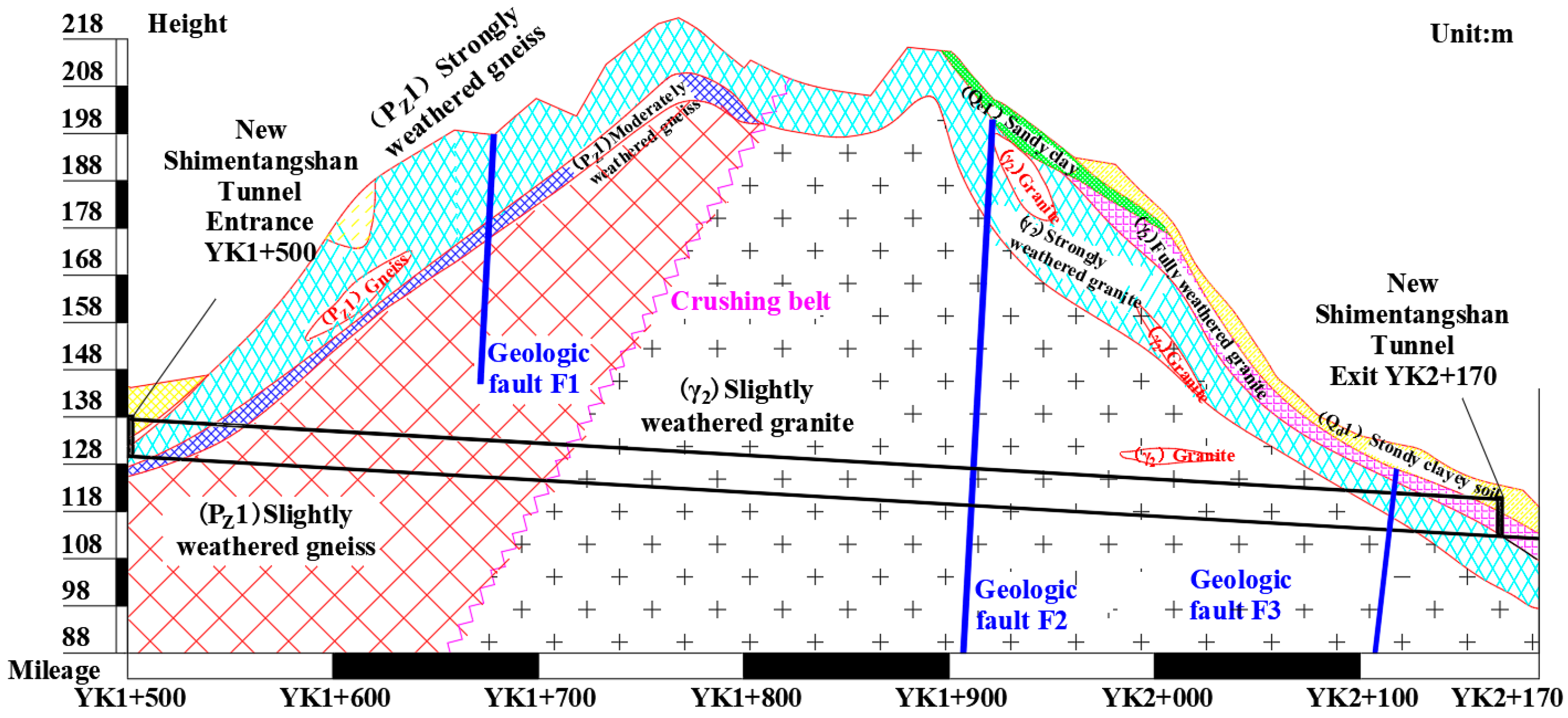
2.1. Overview of Tunnel

The Shimentangshan tunnel is a newly constructed four-lane tunnel located at the junction of Tianhe District and Baiyun District in Guangzhou City, Guangdong Province. It is part of the Hua’nan Expressway expansion project and is situated on the right side of the existing tunnel, approximately 38–41 m away, the overall layout is depicted in Figure 1. The tunnel has a total length of 670 m and an excavation span of up to 20.3 m, a height of 13.5 m, and an excavation area of 214.2 m2. The geological conditions of the tunnel are complex and variable, primarily consisting of grade III to V surrounding rock. The geological survey data show that the site’s strata are divided into several layers, including the quaternary artificial fill layer, quaternary alluvial vial layer, slope diluvium, eluvium, gneiss strata, and granite layer, as shown in Figure 2, and the geomaterial properties of the main strata are shown in Table 1.

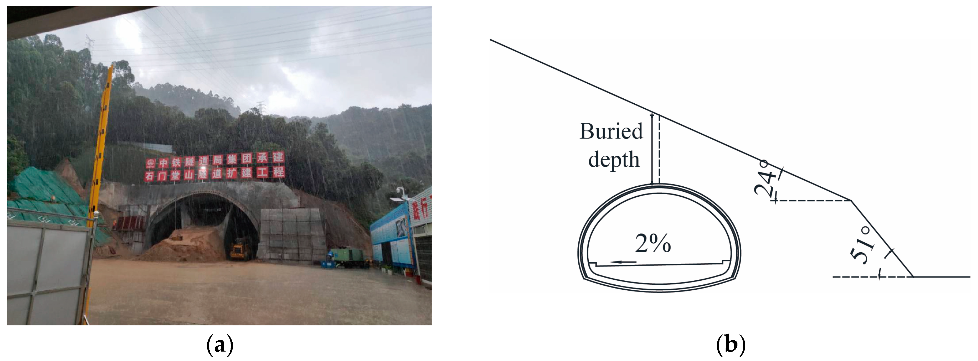
2.2. Overview of the Shallow Unsymmetrical Loading Section

Figure 3 shows the topography of the tunnel portal section. The outlet dark excavation section has a minimum buried depth of only 2.9 m and a surface slope of 24° and 51°, which exhibit typical shallow unsymmetrical loading characteristics.
Figure 2 shows that fault F3 is located in the shallow section of the portal. The rock in this area has undergone strong weathering metamorphism, making it susceptible to softening in water. Additionally, the steep terrain slope and rock surface slope contribute to poor self-stability. Groundwater in this area is primarily composed of quaternary pore diving and bedrock fissure water, and the amount of water in the rainy season is large, resulting in easy deformation of the excavation and collapse, and there is seepage and leakage of water.
During the construction process, groundwater is emitted, causing fine particles in the sandy soil to be lost with the water. This results in a looser sand structure, increased permeability, and intensified loss of groundwater and fine particle soil. The permeability of granite residual soil and fully weathered granite is also strengthened. During tunnel excavation, groundwater can cause issues such as water penetration and mud gushing when the residual and total weathering layers encounter strong or moderately weathered granite.

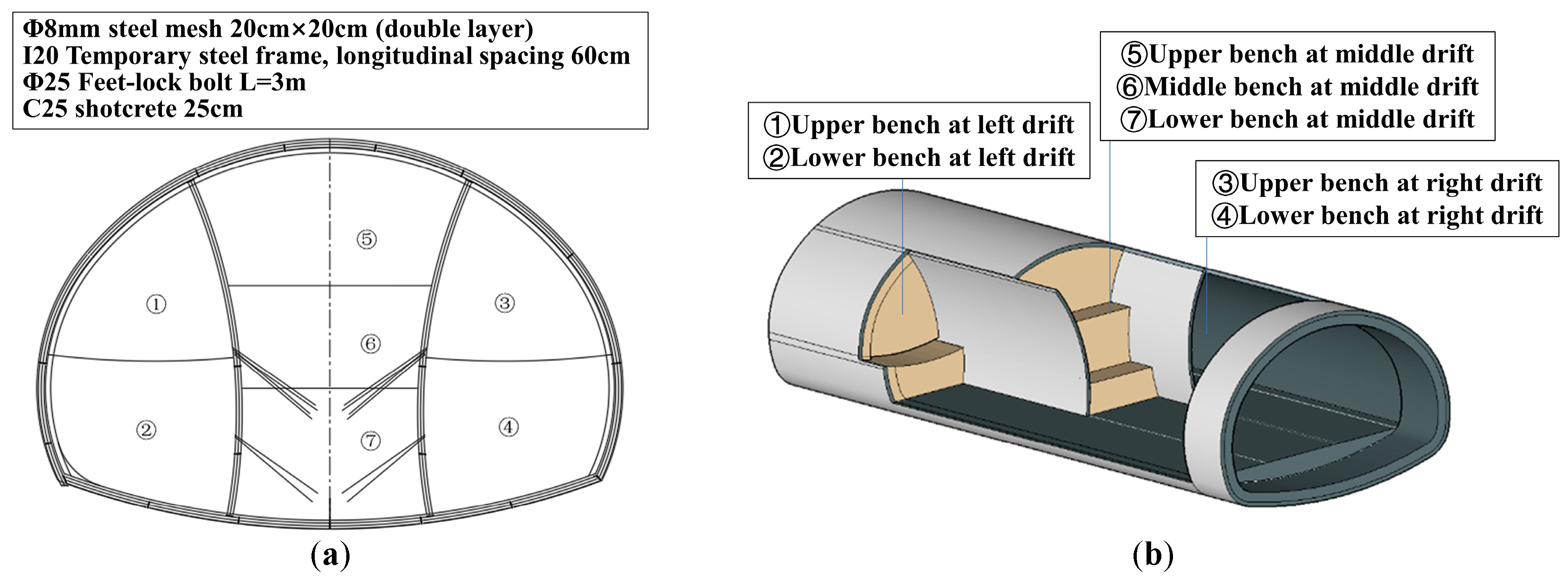
2.3. Construction Scheme

Based on the results of the geological exploration. The surrounding rock of the tunnel portal section is mainly V-class surrounding rock. The tunnel-supporting structure is a composite lining. The lining structure and supporting design parameters are shown in Figure 4. The supporting parameters are as follows: in section YK2 + 164~YK2 + 134, the advance support adopts a 30 m long Φ108 mm pipe roof umbrella system; in section YK2 + 131~YK2 + 090, it adopts double-layer grouting small pipes. The initial support is composed of an H200 × 200 type steel frame, double-layer Φ8 mm steel mesh, 30 cm thick C25 shotcrete, and a 3.5 m long Φ25 mm feet-lock bolt. The reserved deformation amount is 18 cm, and the secondary lining adopts C40 reinforced concrete with a thickness of 70 cm.
The construction method used is the double-side drift method, as shown in Figure 5. The temporary support parameters are as follows: I20b steel frame is used with a longitudinal spacing of 60 cm. Double-layer Φ8 mm steel mesh is hung with a grid spacing of 20 cm × 20 cm. A 25 cm thick C25 early strength concrete is sprayed, and a 3 m long Φ25 mm feet-lock bolt is used.

3. Field Test

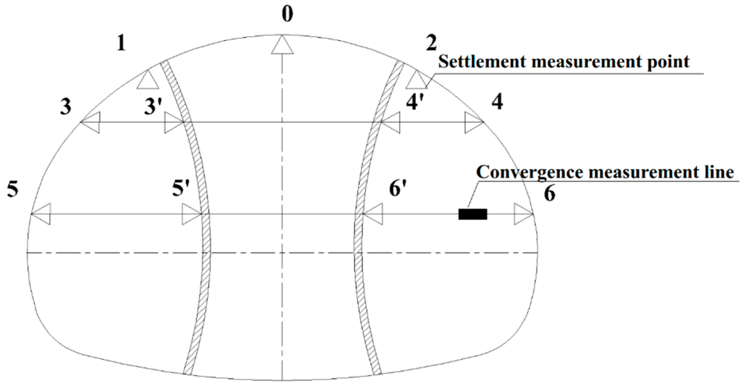
3.1. Field Monitoring Scheme

The exit section in the newly built Shimentangshan tunnel belongs to a shallow super-large-span tunnel with unsymmetrical loading. A test section was set up in the exit section, and the total station was used to monitor the arch settlement and convergence of the tunnel’s initial support in the field to obtain the amount of deformation and the deformation pattern. The layout of the deformation measuring points is shown in Figure 6. The arch settlement consists of three positions: the left drift arch (point 1), the middle drift arch (point 0), and the right drift arch (point 2). The convergence measurement line includes the left drift arch waist (3–3′), the left drift arch foot (5–5′), the right drift arch waist (4–4′), the right drift arch foot (6–6′), as well as the main section arch waist (3–4) and the main section arch foot (5–6), totaling six measurement lines.

3.2. Monitoring Results

The results of arch settlement monitoring for three sections, YK2 + 128, YK2 + 132, and Y2 + 134, are listed in Table 2. YK2 + 132 is selected as a typical section to analyze the spatial and temporal variation law of the arch settlement. The duration curve of each monitoring point is shown in Figure 7.
As shown in Table 2, the highest settlement value for each section is found in the left drift (No.1 point). The maximum settlement value is 107.0 mm, which is less than the reserved deformation amount of 180.0 mm. This indicates that the initial support can control the tunnel deformation and eventually lead to a stable state. When comparing the settlement value in each drift, it is evident that the left drift experiences the largest settlement, followed by the middle drift, and finally the right drift. This observation is made in the context of the double-side drift method.
Figure 7 shows that the arch settlement undergoes three stages: rapid growth, slow deformation, and stabilization, and finally reaches a relatively stable state. The excavation of the right drift has led to a significant increase in the settlement rate of the left drift. Similarly, the excavation of the middle drift has resulted in a significant increase in the settlement rate of both the left and right drifts. These findings suggest that the excavation of the posterior drift has a significant impact on the structural stability of the drift. During the period between the excavation of each drift and the removal of temporary support, the average settlement rate of the left drift was 0.84 mm/d, while the average settlement rate of the right drift was 0.49. The settlement rate of the middle drift reached 1.11 mm/d, the highest among all drifts. This indicates that the arch settlement rate of the middle drift is higher than that of the other drifts, resulting in a greater final settlement compared to the right drift excavated first. The left drift, which is located on the deep buried side, experienced the longest deformation time and the most disturbances, resulting in the greatest final settlement among all drifts. After the temporary support was removed, the arch of the drift experienced short-term and rapid settlement, followed by a gradual stabilization. This indicates that the stress in the arch structure was distributed at this time, and the slow deformation of the middle drift was also halted, resulting in the gradual stabilization of the arch structure.
The results of convergence monitoring for three sections, YK2 + 128, YK2 + 132, and Y2 + 134, are listed in Table 3. YK2 + 132 is selected to analyze the law of convergence. The duration curve of each monitoring point is shown in Figure 8.
As shown in Table 3, the highest convergence value for each section is found in the left drift (5–5′). The maximum convergence value is 108.8 mm. and this value is less than the reserved deformation amount of 180.0 mm, indicating that the initial support can control the tunnel deformation and eventually lead to a stable state. When comparing the convergence value in each drift, it is evident that the left drift experiences the largest convergence, followed by the middle drift. Moreover, the convergence value of the main section is negative, which means that the arch structure of the tunnel has expanded outward after the temporary support is removed. This observation is made in the context of the double-side drift method.
Figure 8 illustrates that the convergence at each monitoring point underwent three stages: rapid growth, slow deformation, and stabilization. The deformation rate of both side drifts decreased after the lower bench excavation, attributed to the improved condition of the surrounding rock at the lower level, enhancing the stability of the supporting structure. The convergence rate of the left drift increased significantly after excavating the right drift. This suggests that the drift excavation on the shallow side caused the unloading of the original rock load, resulting in an increase in horizontal stress on the deep side. During the excavation of the middle drift, the convergence value of the left drift decreased slightly, while the convergence value of the right drift remained relatively stable. This indicates that the horizontal stress on the support structure of the shallow side is not significant after excavation of the adjacent drift. Upon removal of the temporary support, the main section undergoes horizontal deformation due to the extrusion of the surrounding rock. The arch support structure quickly stabilizes the deformation. The stress distribution of the structure is analyzed in combination with the analysis of the arch settlement. Once the original load from the temporary support is removed, the arch support structure experiences settlement, and both sides expand outward according to a certain rule. The removal of the temporary support mainly affects the vertical load sharing.

4. Numerical Simulation

Based on the analysis above, it is evident that the double-side drift method used to construct the shallow unsymmetrical loading section of the super-large-span tunnel portal results in significant deformation of the supporting structure, increased disturbance to the surrounding rock during sequential excavation, and significant influence between drifts, and large final deformation. To find appropriate construction methods and support means for controlling the deformation of support structures and surrounding rock stability, the numerical simulation method is conducted to analyze the existing support design and verify the model’s rationality and parameters. The article analyses the construction sequence of the double-side drift method and the proportion of the drift using the given model and parameters. Based on this analysis, the article proposes a stability control technology that is suitable for the shallow unsymmetrical loading section of the super-large-span tunnel portal.

4.1. Numerical Model Establishment

The deformation of the tunnel support structure under different working conditions was calculated using FLAC3D numerical simulation software. To eliminate the boundary effect on the test results, the left, right, and lower boundaries of the model are taken to be three times the diameter of the tunnel, and upper boundaries are determined in accordance with the actual situation. Figure 9 displays the model of a shallow unsymmetrical loading section based on the newly built Shimentangshan super-large-span highway tunnel. Fixed boundaries are applied on the left and right sides, as well as the front and back sides, while the bottom of the model is constrained. The top of the model is left free for deformation. The model does not include secondary lining during the construction process.
Numerical simulation process of double-side drift method: (1) Simulation of initial ground stress → (2) Construction of reinforcement area → (3) Excavation at section ①, cycle length of 0.6 m, construction of initial support, temporary support and anchor bolt → (4) Excavation at section ②, cycle length of 0.6 m, Steps in length of 3 m, construction of initial support, temporary support and anchor bolt → (5) Excavation at section ③, Cycle length of 0.6 m, construction of initial support, temporary support and anchor bolt → (6) Excavation at section ④, cycle length of 0.6 m, benches in length of 3 m, construction of initial support, temporary support and anchor bolt → (7) Excavation at section ⑤⑥⑦, cycle length of 0.6 m, benches in length of 3 m → (8) Remove the temporary support.

4.2. Model Parameters

The model only considers the effects of gravity without any additional loads. The Mohr–Coulomb constitutive model was applied to the surrounding rock and the reinforced zone, while the elastic constitutive model was used for the initial support, temporary support, feet-lock bolts, and bolts. The physical and mechanical parameters of the surrounding rock in the numerical calculation model were selected based on the survey and design data of the newly built Shimentangshan tunnel and the recommended value in the Specifications for Design of Highway Tunnels [33]. And referring to the relevant literature [34], the physical and mechanical parameters of the surrounding rock were enhanced accordingly. Table 4 lists the physical and mechanical parameters of the surrounding rock and the reinforcement area.
The initial support structure and temporary support structure primarily consist of shotcrete and a steel frame. When conducting numerical simulations, the support structure is treated as a unified entity, with the modulus of elasticity and density of the steel frame converted to match those of the shotcrete. The calculation formula is presented in Equations (1) to (2), and the physical and mechanical parameters of the support structure post-conversion are detailed in Table 5.
E = E h + A g   ×   E g A
γ = γ h + A g A γ g γ h
where E is the equivalent elasticity modulus of initial support, Eg is the elasticity modulus of steel frame, Ag is the cross-sectional area of steel frame, Eh is the modulus of elasticity of shotcrete, A is the total cross-sectional area, γ is the equivalent gravity of initial support, γg is the gravity of steel frame, and γh is the gravity of shotcrete.

5. Results

According to existing research, the deformation of the supporting structure and the plastic zone of the surrounding rock are reliable indicators of the tunnel’s stability. Therefore, it is important to consider the tunnel’s deformation and plastic zone when evaluating its stability.

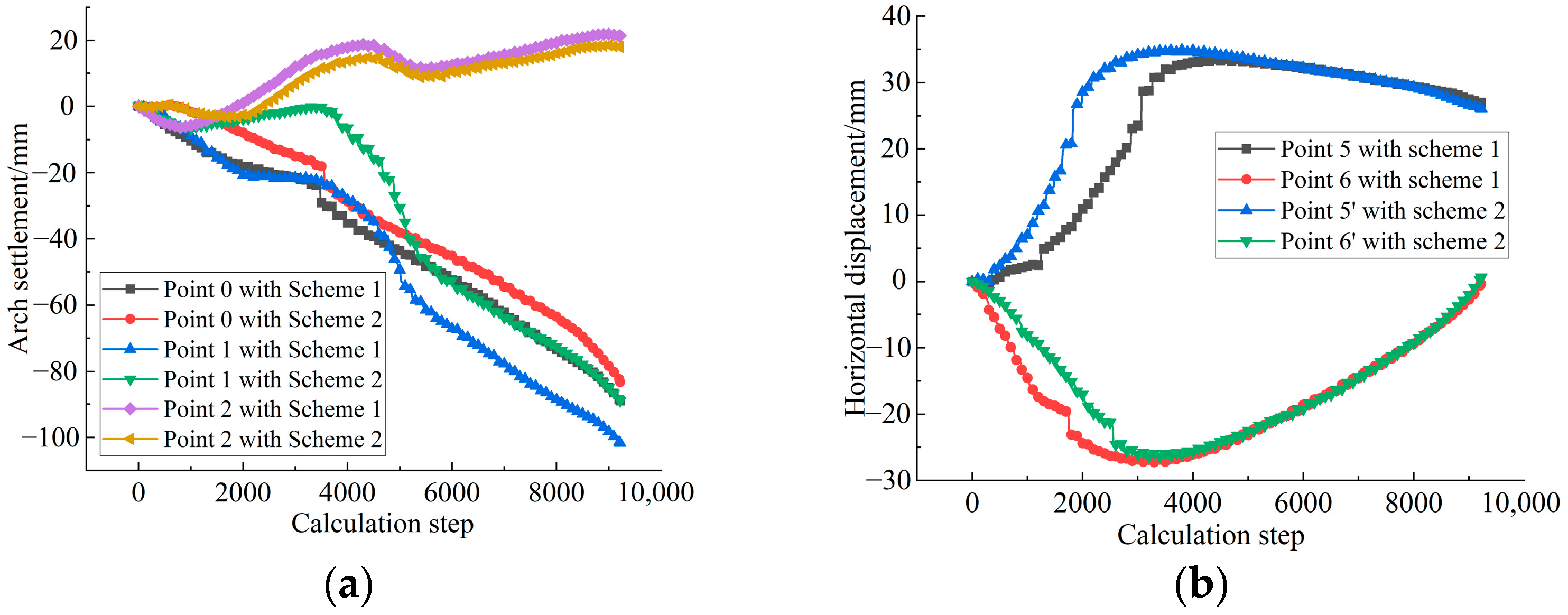
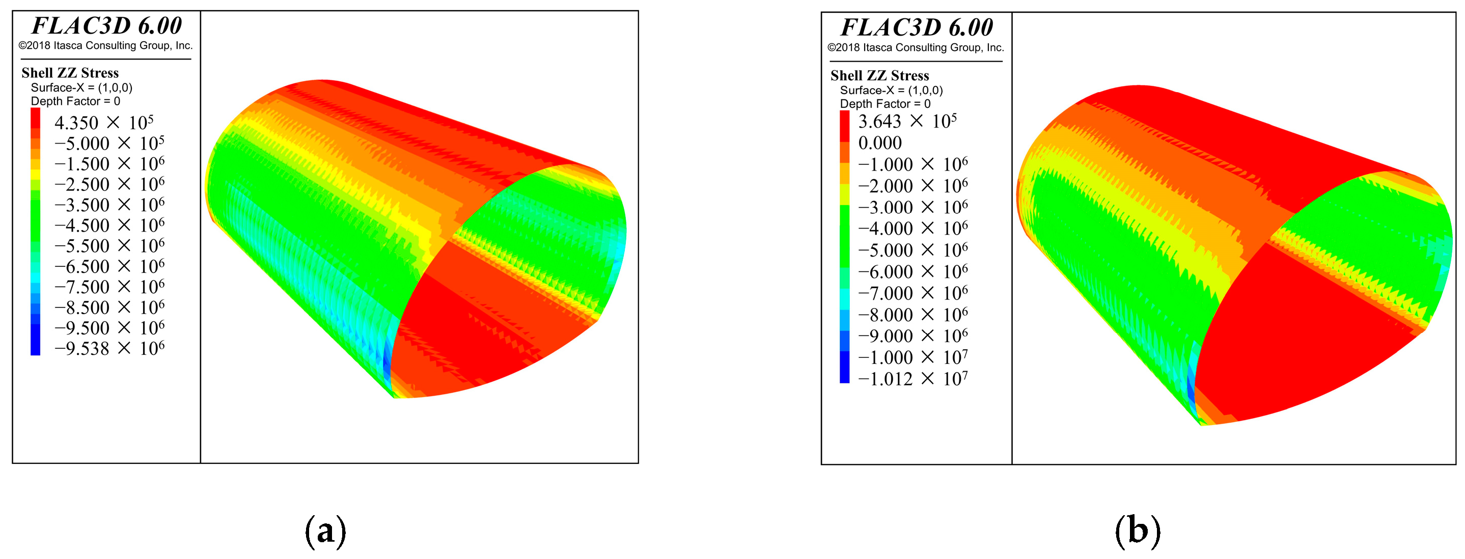
5.1. Different Excavation Sequence

To better guide the site construction, this study focuses on the comparative analysis of the influence of excavation sequence on the stability of surrounding rock during the construction of a shallow unsymmetrical loading section of a super-span tunnel. The study presents various excavation sequences for the double-side drift method, including the deep-side-first excavation sequence and the shallow-side-first excavation sequence. In Scheme 1, the specific construction sequence is as follows: (1) Excavation of deep side upper bench → (2) Excavation of deep side lower bench→ (3) Excavation of shallow side upper bench → (4) Excavation of shallow side lower bench → (5) Excavation of middle drift. In Scheme 2, the specific construction sequence is as follows: (1) Excavation of shallow side upper bench → (2) Excavation of shallow side lower bench → (3) Excavation of deep side upper bench → (4) Excavation of deep side lower bench → (5) Excavation of middle drift. The simulation results of arch settlement, horizontal displacement, vertical stress, and plastic zone at two schemes are shown in Figure 10, Figure 11 and Figure 12.
From the arch settlement duration curve in Figure 10a, points 0 and 1 show continuous settlement changes, and point 2 shows a slow uplift trend; comparing the simulation results of Scheme 1 and Scheme 2: in Scheme 1, points 0 and 1 settled by 89.0 mm and 101.7 mm, respectively, while point 2 was uplifted by 21.4 mm; in Scheme 2, points 0 and 1 settled by 83.2 mm and 89.0 mm, respectively, while point 2 was uplifted by 17.9 mm. By comparing the results, it can be found that when the scheme of the deep side is adopted, the arch settlement of the deep side and the drift in the middle is greater than the scheme of shallow-side-first excavation, and the uplift deformation of the arch of the drift on the shallow buried side also shows the result that the first excavation on the deep side is greater than the first excavation on the shallow side.
By analyzing the simulation results of the horizontal displacement of the tunnel from Figure 10b, it is evident that both points 5 and 6 exhibit a convergence pattern to the simulation results of Scheme 1 and Scheme 2. Specifically, the horizontal displacement of point 5 is 27.0 mm, while that of point 6 is −0.3 mm. In Scheme 2, the horizontal displacement of point 5 is 26.1 mm, and that of point 6 is 0 mm. The horizontal displacements generated by the scheme of the deep-side-first excavation and the shallow-side-first excavation are basically the same, with no significant gap.
Figure 11 illustrates the vertical stress contours of the initial support structure. The contours reveal compressive stresses are evident at the sidewalls of the initial support, while tensile stresses are evident at the tunnel arch and the inverted arch. The highest principal stresses are located at the foot of the arch on the deeply buried side, characterized by compressive stresses. Specifically, Scheme 1 exhibits a maximum compressive stress of 9.54 MPa, whereas Scheme 2 shows 10.12 MPa. Conversely, the top of the arch experiences the maximum tensile stresses, with Scheme 1 recording 0.44 MPa and Scheme 2 at 0.36 MPa. Notably, the maximum tensile stress occurs at the top of the arch, where Scheme 1 reaches 0.44 MPa and Scheme 2 measures 0.36 MPa. Importantly, both the maximum compressive and tensile stresses of the initial support are below the standard strength value of C25 shotcrete. This observation suggests that excavating the shallow buried side first is advantageous as it allows the initial support to supply compressive stress effectively, thereby controlling the deformation of the support structure.
Figure 12 shows the distribution of the plastic zone at the end of tunnel excavation for both schemes. The figure indicates an asymmetric distribution of the plastic zone of surrounding rock due to the influence of topographic bias. However, the distribution of the plastic zone of surrounding rock differs due to the excavation sequence. Plastic deformation is mainly distributed in the vault, left arch, left-side wall, right-side wall, and left-inverted arch under Scheme 1. In contrast, Scheme 2 has a smaller plastic deformation area than Scheme 1, with no large range of plastic deformation. The deep-side-first excavation scheme produces a larger range of plastic deformation than the shallow-side-first excavation scheme.
Based on the results above, the arch settlement and plastic zone of the shallow-side-first excavation were found to be less than those of the deep-side-first excavation. However, there was no significant difference in horizontal convergence. Overall, the excavation scheme for the shallow-side-first is preferable to that of the deep-side-first.

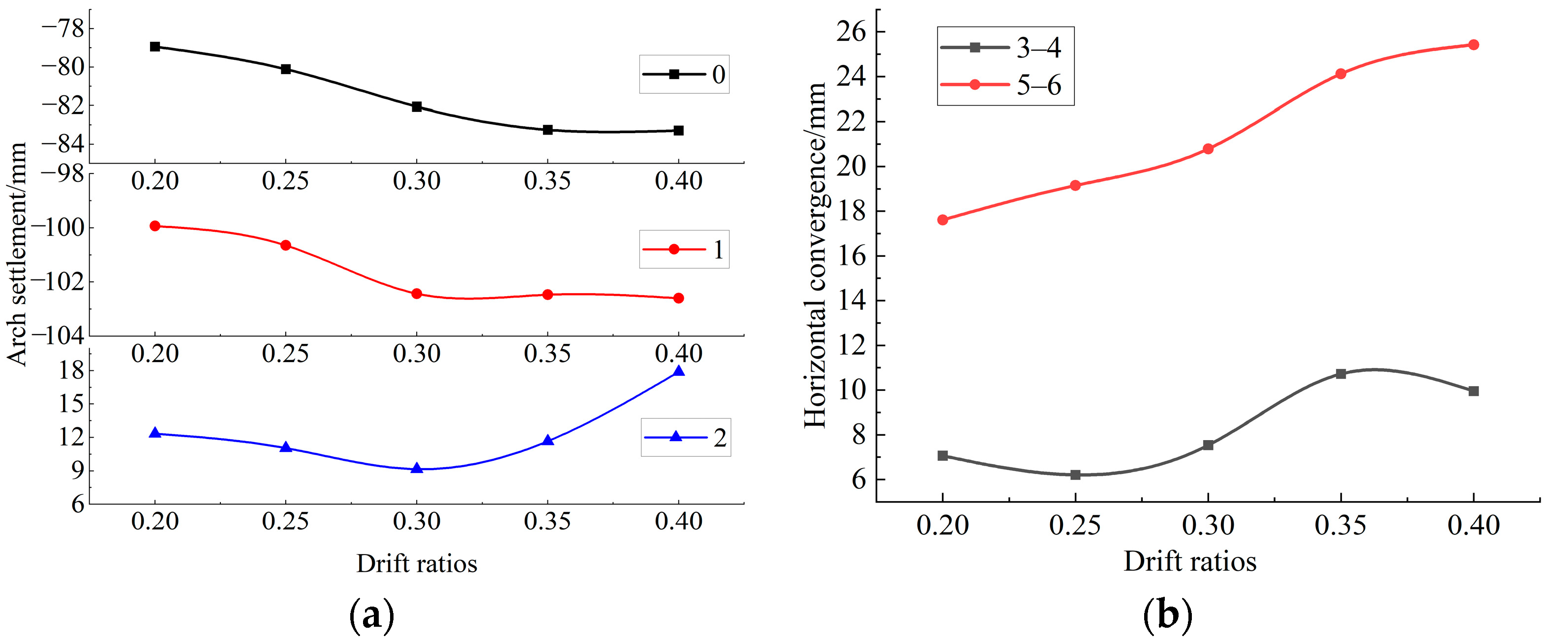
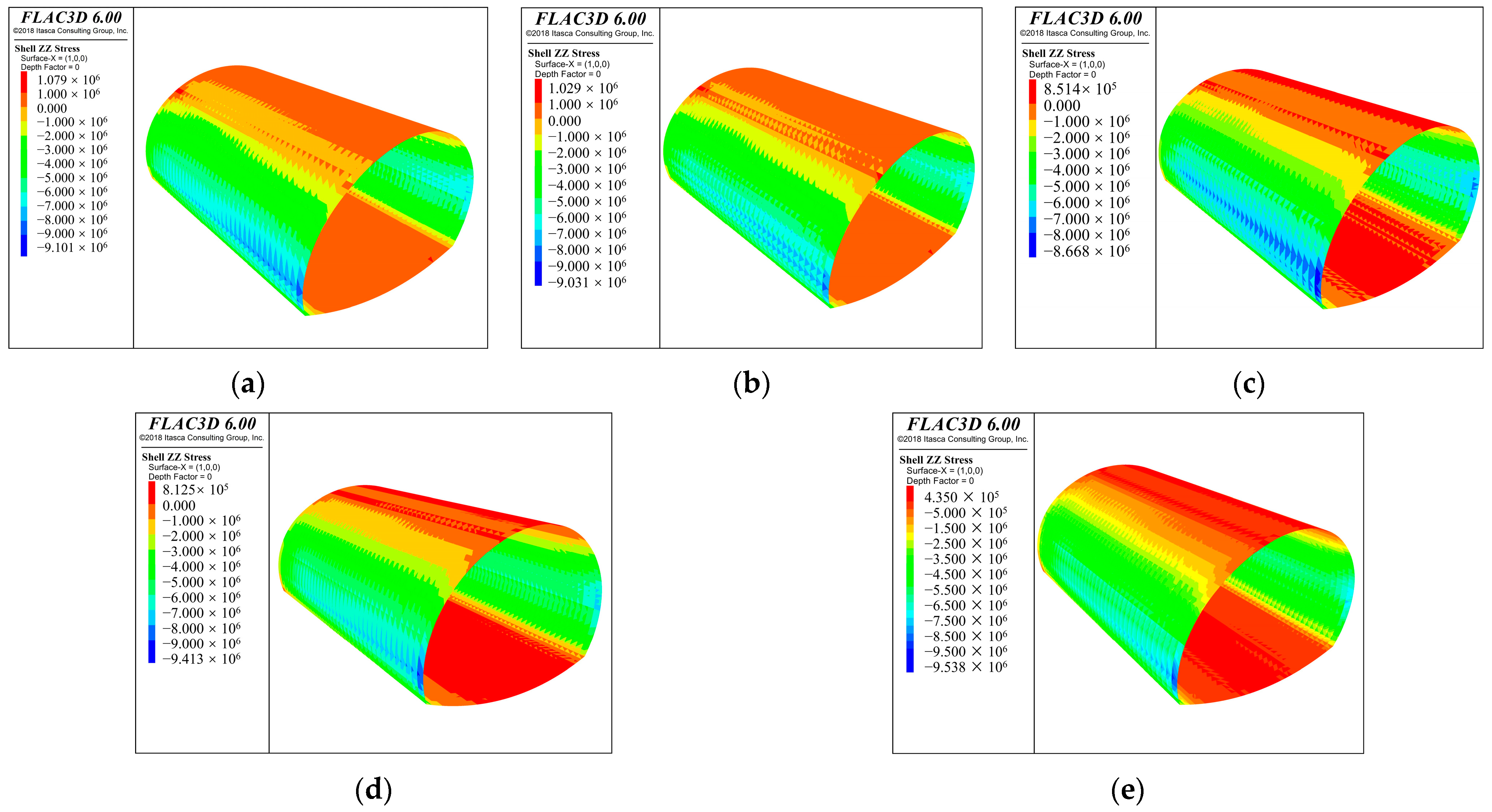
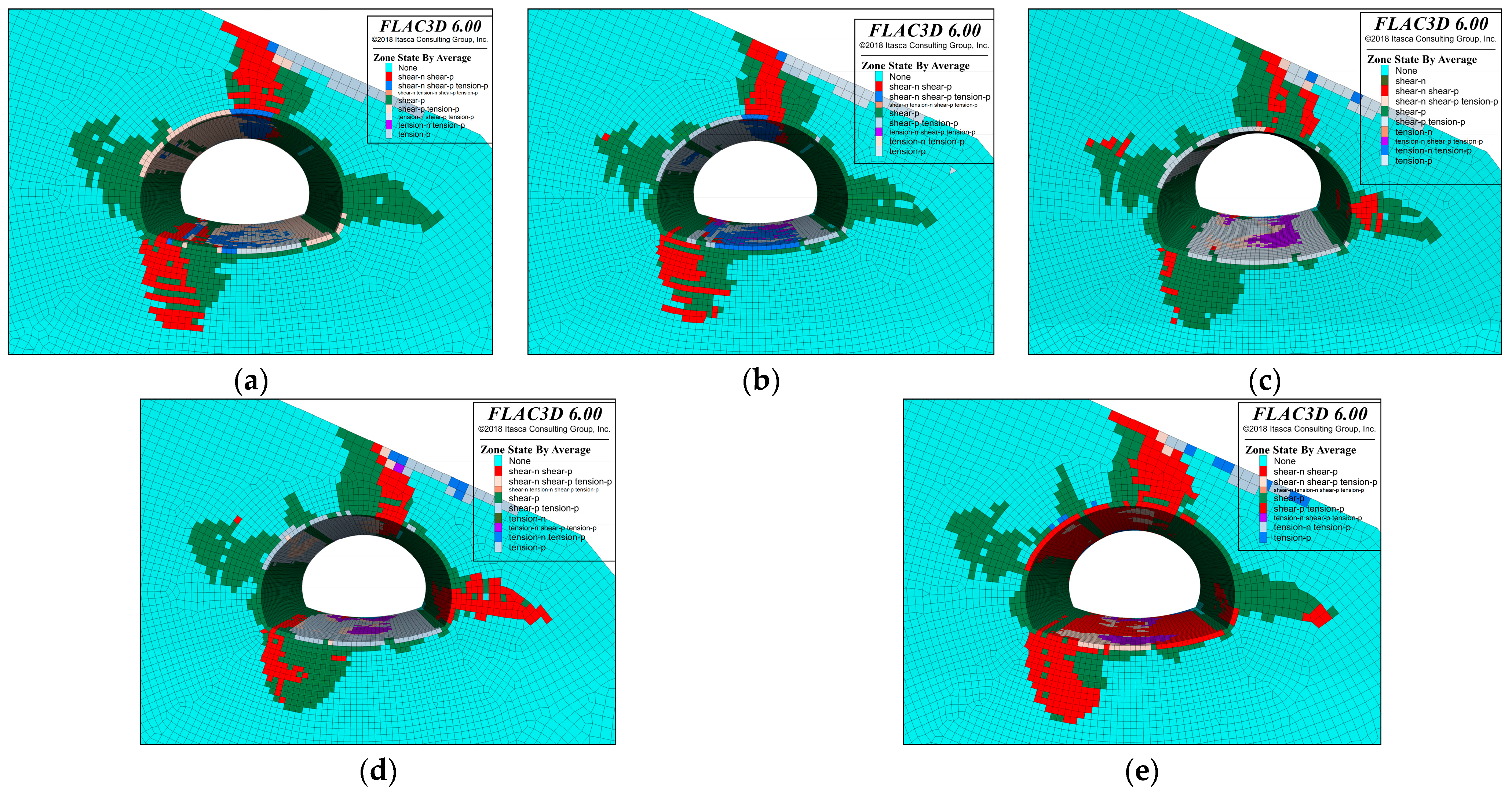
5.2. Different Drift Ratio

The double-side drift method is commonly used in the construction of large-span highway tunnels to divide into smaller sections through sequential excavation. This study analyzed the control effect of the surrounding rock stability using numerical calculations for drift ratios of 0.20, 0.25, 0.30, 0.30, and 0.45. To enable a comparison of the impact of the left and right drifts on the surrounding rock pressure of the middle drift, while keeping other factors constant, the tunnel excavation size, physical and mechanical parameters of the surrounding rock, and supporting structure are consistent with the test section. The ratio of the left and right drift spans to the total tunnel span is also consistent. Figure 13, Figure 14 and Figure 15 show the simulation results of arch settlement, horizontal convergence, vertical stress, and plastic region distribution at different drift ratios.
The simulation results of the tunnel arch settlement were analyzed. It was found that both point 0 and point 1 are sinking and changing, while point 2 shows uplift. A comparison was made between the simulation results of different drift ratios. When the ratio of the drifts on both sides is less than 0.3, as the proportion of drifts on both sides increases, the arch settlement of point 0 and point 1 also increases significantly, while the uplift deformation of point 2 decreases, and the change is small. When the ratio of the drifts on both sides exceeds 0.3, with an increase in the proportion of drifts on both sides, the settlement of the arch at point 0 and point 1 continues to gradually increase, and the change is small. Additionally, the uplift and deformation of point 2 is also gradually increasing, with a relatively large change range. When comparing the drifts on both sides, if they are small, the settlement of the deep side and the middle drifts is large, and it is heavily affected by the percentage of drifts on either side. Conversely, if the drifts on both sides are small, the deformation of the shallow side is small, and it is less affected by the percentage of drifts on either side. When the percentage of drifts on both sides is large, the deformation of deep side and middle drifts is less affected by the percentage of drifts on both sides, while the deformation of shallow side drifts is more affected by the percentage of drifts.
As shown in Figure 13b, it is evident that the horizontal convergence of the arch foot is greater than that of the arch waist. The horizontal convergence shows a trend of gradual increase with the increase in the ratio of drifts on both sides, and the greatest increase in convergence is observed when the ratio of drifts on both sides is between 0.25 and 0.35.
Figure 14 illustrates the vertical stress contours of the initial support structure with different drift ratios. The contours reveal compressive stresses are evident at the sidewalls of the initial support, while tensile stresses are evident at the tunnel arch and the inverted arch. The highest principal stresses are located at the foot of the arch on the deeply buried side, characterized by compressive stresses. The initial support experiences a maximum compressive stress of 9.10 MPa and a maximum tensile stress of 1.08 MPa when the ratio of the drifts on both sides is 0.2. As the ratio increases, both compressive and tensile stresses decrease. At a ratio of 0.3, the maximum compressive stress drops to 8.67 MPa and the maximum tensile stress decreases to 0.85 MPa. Subsequently, as the ratio of drifts on both sides further increases, the compressive stress rises while the tensile stress continues to decrease. When the ratio reaches 0.4, the maximum compressive stress peaks at 9.54 MPa, and the maximum tensile stress drops to 0.44 MPa. This trend indicates that the initial support’s compressive stress initially decreases and then increases with the ratio of the drifts on both sides. The structure reaches its safest state when the ratio of drifts is 0.3, as the compressive stress controlling the structure’s safety is minimized at this point.
Figure 15 shows the distribution of the plastic zone of the surrounding rock at the end of tunnel excavation under five different drift ratios. The plastic zone exhibits an asymmetrical distribution due to topographic bias. The ratio of drifts on both sides affects the distribution of the plastic zone in the surrounding rock. The plastic zone of the surrounding rock is primarily located in the vault, left-arch waist, left-side wall, right-side wall, and left-side arch of the tunnel. As the drift ratios on both sides increase, the plastic zone at the left arch waist gradually expands, and the scope of the plastic zone of the surrounding rock also gradually increases.
Based on the results above, five different excavation schemes with varying drift ratios were identified. As the drift ratio increases, there is an increasing trend in drift arch settlement, horizontal convergence, and the plastic zone of the surrounding rock. Therefore, it is recommended to control the span of the drift to reduce the disturbance of the surrounding rock, while still meeting the needs of the construction space.

6. Optimization Benefit Analysis

6.1. Efficiency and Economic Benefits Analysis

The construction efficiency is primarily affected by the ratio of drifts. A smaller ratio of left and right drifts results in a smaller excavation section, making mechanical excavation and slagging more challenging. Manual excavation and cleanup of soil and rock left at the upper bench platform are necessary in this scenario. For instance, with a ratio of 0.2, the area of both sides of the drifts is only 28 m2. Five people are needed for each cleanup, taking 3 h per cycle. With a section length of 70 m using the double-side drift method, the total time required is 280 h. Conversely, with a ratio of 0.3, the area of the guide holes increases to 48 m2, allowing for mechanical excavation and slagging on the benches, thus saving 280 h of manpower.
When the ratio of left and right drifts is small, mechanical excavation and slag removal from the upper platform becomes challenging. Manual supplementary excavation is necessary after the main mechanical excavation, followed by clearing soil and rock to the lower platform for loading and transportation out of the tunnel. In Section 6.1, it is shown that with a drift ratio of 0.2, the area of the drift is only 28 m2 and the cyclic footage is 1.5 m. According to calculations, the upper bench of both side drifts requires manual labor to clear 21 m3 of soil and rock. With a tunnel segment length of 70 m using the double-side drift method, the total soil and rock to be cleared manually is estimated at 2614 m3, resulting in a manual cleaning cost of CNY 52,280. Optimizing the construction drift ratio can help reduce the labor costs associated with this process.

6.2. Stability Control Measures

Based on the results of the field test and numerical simulation analysis, starting from the control of tunnel deformation and stability, and considering the control effect of the construction scheme on the stability of the surrounding rock, the following stability control measures are formulated:
  • Strengthen the advance support. The tunnel section adopts a Φ108 mm hot rolled steel pipe roof umbrella system with a thickness of 6 mm; the length of the pipe roof umbrella system is 30 m, the ring spacing is 40 cm, and the lap length is 3 m. After entering the tunnel, with the increase in the buried depth, the double-layer grouting pipe is adopted, with lengths of 3 m and 4.5 m, respectively, and the longitudinal spacing is 1.8 m and 3 m, respectively.
  • Improve the initial support stiffness. Add a feet-lock anchor pipe at the arch frame of each drift bench and temporary steel frame joint. The external insertion angle should be 20~30°, and I20b I-steel temporary horizontal support can be installed if necessary.
  • Apply bolt and surrounding rock grouting. Adopt a hollow grouting bolt, with a length of 5 m, and spacing of 1.0 m × 0.6 m, and the grouting strength is not lower than M20.
  • Control the length of the benches. The excavation length of the drift benches on both sides should be controlled at 3~5 m, and the drifts on both sides should not be less than 15 m.
  • Optimize the construction sequence. Super-large-span tunnels have a flat structure, leading to more complex structural deformation and forces compared to other tunnel types. In contrast to the research findings of Ding et al. [28], the simulation results found that the excavation method of the shallow side first and then the deep side for super-large-span tunnels is more favorable for controlling structural deformations. The study suggests that when super-large-span tunnels are constructed using the double-side-wall drift method to traverse shallow buried unsymmetrical sections, the construction sequence of excavating the shallow side first, then excavating the deep side, and finally excavating the middle drift is recommended.
  • Optimize the proportion of the drifts on both sides. The ratio of drifts on both sides of the super-large-span tunnel not only significantly affects the structural forces but also plays a crucial role in construction efficiency and economic benefits. Based on comprehensive analysis results, it is recommended to use a ratio of approximately 0.3 for on-site construction.

7. Conclusions

Relying on the newly built Shimentangshan tunnel, this paper analyzes the deformation rules, the reasonable construction sequence, and the drift ratio of a shallow unsymmetrical loading section of a super-large-span tunnel based on a field test and numerical simulation, and puts forward stability control measures. The conclusions are drawn as follows:
(1)
The arch settlement and horizontal convergence of the monitoring section mainly experience three stages: rapid growth, slow deformation, and stabilization. The deformation lasts a long time and finally reaches a relatively stable state. The deformation of each part is less than the reserved deformation; the tunnel deformation is the largest on the left, followed by the smallest on the right; and temporary support has a great impact on the initial support structure. The removal of the temporary support makes the deformation of the initial support quickly enter into a stable state, which mainly affects the resharing of the vertical load.
(2)
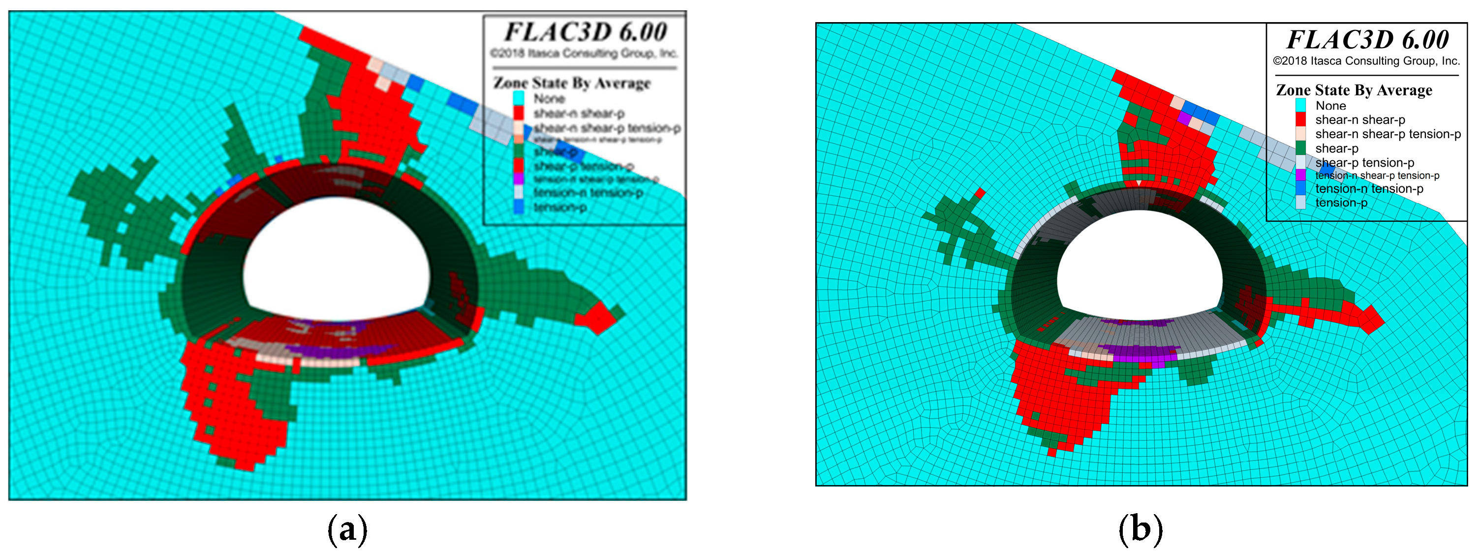
With the shallow-side-first excavation scheme, the arch settlement and plastic zone of the surrounding rock are smaller than the deep-side-first excavation scheme, while the horizontal convergence has no obvious difference, so the shallow-side-first excavation scheme is slightly better than the deep-side-first excavation scheme; with the increase in the ratio of drifts, the arch settlement of the various drifts and the horizontal convergence show a tendency to increase, and the scope of the plastic zone also gradually increases, with the initial support structure stress exhibiting a pattern of decreasing followed by an increase as the drift ratio increases. The structure reaches its most stable stress state at around 0.3.
(3)
According to the field test results of tunnel deformation and the numerical simulation results of the construction scheme, control measures such as strengthening the advance support, improving the stiffness of the initial support, adopting bolt and grouting of surrounding rock, controlling the length of the benches, and optimizing the construction sequence and the proportion of the drifts on both sides are proposed.
(4)
The scope of this study is focused on construction optimization, but it is important to note that when dealing with shallow buried unsymmetrical strata, design parameters like flatness and unsymmetrical degree of super-large-span tunnels play a significant role in structural stability. Future research should consider delving deeper into tunnel section and support structure design.

Author Contributions

Conceptualization, L.W. and C.T.; Methodology, Y.L.; Validation, C.Z. and X.S.; Formal analysis, C.T.; Investigation, C.T.; Resources, Y.L.; Data curation, Z.L.; Supervision, L.W. and Y.L. All authors have read and agreed to the published version of the manuscript.

Funding

The authors would like to acknowledge the financial support provided by the National Natural Science Foundation of China (grant no. 5197081888), the Science Fund for Distinguished Young Scholars in Shaanxi Province (grant no. 2020JC-28), the Collaborative Research Project with Shandong Provincial Communications Planning and Design Institute Group CO., LTD. (grant no. 2020-KJ-046).

Institutional Review Board Statement

Not applicable.

Informed Consent Statement

Not applicable.

Data Availability Statement

The data presented in this study are available upon request from the corresponding author. The data are not publicly available due to privacy.

Acknowledgments

The authors are grateful for the comments provided by the anonymous reviewers.

Conflicts of Interest

Authors Li Wan, Xing Shao, and Changan Zhang were employed by the company Shandong Provincial Communications Planning and Design Institute Group CO., LTD. The remaining authors declare that the research was conducted in the absence of any commercial or financial relationships that could be construed as a potential conflict of interest.

References

  1. Liu, W.W.; Chen, J.X.; Chen, L.J.; Luo, Y.B.; Shang, Q.C.; Zhang, L.X.; Gao, S.K.; Jia, H.Y. A Rational Construction Method and Deformation Control System of Tunnelling in Extremely Soft and Fractured Chlorite Schist Medium. Tunn. Undergr. Space Technol. 2024, 143, 105472. [Google Scholar] [CrossRef]
  2. Liu, W.W.; Chen, J.X.; Luo, Y.B.; Chen, L.J.; Zhang, L.X.; He, C.L.; Shi, Z.; Xu, Z.L.; Zhu, H.Y.; Hu, T.T.; et al. Long-term Stress Monitoring and In-Service Durability Evaluation of A Large-Span Tunnel in Squeezing Rock. Tunn. Undergr. Space Technol. 2022, 127, 104611. [Google Scholar] [CrossRef]
  3. Luo, Y.B.; Zhou, S.; Chen, J.X.; Liu, W.W.; Chen, L.J.; Li, Y.; Wu, Y.F. Mechanical Calculation Model and Research on Construction Mechanical Behavior of Middle Diaphragm in Upper Bench CD Method for Super-large Span tunnel. China J. Highw. Transp. 2020, 33, 235–248. [Google Scholar]
  4. Luo, Y.B.; Dong, F.F.; Wang, C.W.; Chen, J.X.; Zhu, T.T.; Zhang, L.X.; Liu, W.W. A Surrounding Rock Pressure Calculation Method for Super-Large-Span Highway Tunnels Considering Sequential Excavation. Chin. J. Rock Mech. Eng. 2022, 41, 1637–1646. [Google Scholar]
  5. Liu, X.J.; Zhang, Y.X. Analysis of Reasonable Excavation Sequence and Stress Characteristics of Portal Section of Shallow Tunnel with Unsymmetrical Loadings. Chin. J. Rock Mech. Eng. 2011, 30, 3066–3073. [Google Scholar]
  6. Chen, Y.; Luo, Y.B.; Gao, J.M.; Gao, S.C.; Jiao, Y.Z. Application of Double-layer Initial Support in Super-large-span Highway Tunnel. Sci. Technol. Eng. 2020, 20, 10486–10491. [Google Scholar]
  7. Zhang, J.R.; Wu, J.; Yan, C.W.; Gou, X.M.; Ye, L.; Feng, J.M. Construction Technology of Super-large Section of Highway Tunnels with Four or More Lanes in China. China J. Highw. Transp. 2020, 33, 14–31. [Google Scholar]
  8. Wang, W.F.; Mei, Z. Study of Application of Bench Method to Shallow-buried Asymmetrically-pressured Railway Tunnel of Super-large Cross-section. Tunn. Constr. 2017, 37, 1578–1584. [Google Scholar]
  9. Zhou, B.S. Optimizing CRD Construction Techniques for a Super-Shallow Bored Tunnel. Mod. Tunn. Technol. 2018, 55, 186–190. [Google Scholar]
  10. Luo, Y.B.; Chen, J.X. Monitoring and Analysis of the Deformation of the Middle Wall During the Construction of a Shallow Soil Tunnel by the CRD method. Mod. Tunn. Technol. 2011, 48, 105–109. [Google Scholar]
  11. Lei, M.F.; Peng, L.M.; Shi, C.H.; Wang, L.C.; Liu, Z.C. Model research on failure mechanism and lining stress characteristics of shallow buried tunnel under unsymmetrical pressure. J. Cent. S. Univ. Sci. Technol. 2013, 44, 3316–3325. [Google Scholar]
  12. Luo, J.W.; Zhang, D.L.; Sun, Z.Y.; Fang, Q.; Liu, D.P.; Xu, T.; Li, R. Numerical modelling and field monitoring study on large-span tunnelling using pretensioned bolt–cable combined support system. Tunn. Undergr. Space Technol. 2023, 132, 104911. [Google Scholar] [CrossRef]
  13. Al Hallak, R.; Garnier, J.; Leca, E. Experimental study of the stability of a tunnel face reinforced by bolts. In Proceedings of the Geotechnical Aspect of Underground Construction in Soft Ground, Tokyo, Japan, 19–21 July 1999. [Google Scholar]
  14. Lyu, C.; Zeng, Z.Q. Upper bound limit analysis of unsymmetrical progressive collapse of shallow tunnels in inclined rock stratum. Comput. Geotech. 2019, 116, 103199. [Google Scholar] [CrossRef]
  15. Zhao, Y.G.; Shao, S.J.; Han, C.L. Simulation on Different Excavation Construction of the Shallow-Buried Tunnel under the uneven Rock Pressure. Rock Soil Mech. 2009, 30, 509–513. [Google Scholar]
  16. Zhang, L.Q.; Gao, D.; Yang, H.; Mu, B.L.; Zhang, L.J.; Xu, Y.M. Study on Influence Scope of Shallow tunnel with unsymmetrical loadings Plastic Zone by Surface Dip and Buried Depth. J. Hebei Inst. Archit. Civ. Eng. 2016, 34, 14–18. [Google Scholar]
  17. Liu, Z.Q. Research on Deformation Monitoring Method and Deformation Law of Shallowly Buried Tunnels with Bias-pressure. Value Eng. 2019, 38, 179–180. [Google Scholar]
  18. Chen, Y.; Lin, C.M.; Huang, J.S.; Huang, Z.B.; Fu, X. The surrounding rock deformation laws of shallow-buried biased super-large cross-section tunnel excavated via CRD method. J. Zhengzhou Univ. Light Ind. Nat. Sci. 2013, 28, 76–79. [Google Scholar]
  19. Shi, Y.Z.; Li, J.F.; Li, W.Y.; Zhou, X.Q. Construction Mechanics of Tunnel with Super-Large Cross-Section and Its Dynamic Stability. J. Shanghai Jiao Tong Univ. 2015, 49, 1023–1029. [Google Scholar]
  20. Zhang, T.; Nie, L.; Zhang, M.; Dao, S.L.; Xu, Y.; Du, C.; Rui, X.J.; He, Y.Y. The Unsymmetrical Coefficient of Unsymmetrical-Loaded Tunnel Based on Field Monitoring and Numerical Simulation. Symmetry 2020, 12, 1793. [Google Scholar] [CrossRef]
  21. Lei, M.F.; Peng, L.M.; Shi, C.H. Model test to investigate the failure mechanisms and lining stress characteristics of shallow buried tunnels under unsymmetrical loading. Tunn. Undergr. Space Technol. 2015, 46, 64–75. [Google Scholar] [CrossRef]
  22. Lei, M.F.; Lin, D.Y.; Yang, W.C.; Shi, C.H.; Peng, L.M.; Huang, J. Model test to investigate failure mechanism and loading characteristics of shallow-bias tunnels with small clear distance. J. Cent. S. Univ. 2016, 23, 3312–3321. [Google Scholar] [CrossRef]
  23. Lei, M.F.; Peng, L.M.; Shi, C.H.; Xie, Y.J.; Tan, L.X. Upper bound analytical solution for surrounding rock pressure of shallow unsymmetrical loading tunnels. J. Cent. S. Univ. 2015, 22, 2339–2347. [Google Scholar] [CrossRef]
  24. Wang, K.Z.; Xiong, Y.; Li, S.; Zhou, X.; Li, Z.K. Deformation Characteristics Analysis of Temporary Support in Unsymmetrical Loading Tunnel Excavation under Composite Support. Symmetry 2023, 15, 830. [Google Scholar] [CrossRef]
  25. Wang, X.Y.; Tan, Z.S.; Liu, Q.L.; Zheng, W.H. Calculation Method for Determining the Wall Displacement and Primary Support Bearing Capacity of Tunnels. Appl. Sci. 2023, 13, 7296. [Google Scholar] [CrossRef]
  26. Zhu, Z.G.; Qiao, C.S.; Gao, B.B. Analysis of construction optimization and supporting structure under load of shallow multi-arch tunnel under unsymmetrical pressure. Rock Soil Mech. 2008, 154, 2747–2752. [Google Scholar]
  27. Mou, Z.H.; Yan, T.; Tian, M.J.; Zhang, J.X. Research on the construction method and reasonable excavation sequence of shallow tunnel with unsymmetrical loadings adjacent to changing roadbed slope. China Civ. Eng. J. 2017, 50, 203–208. [Google Scholar]
  28. Ding, Z.D.; Wang, W.W.; Wen, J.C.; Ji, X.F. A Study on Construction Sequence of Shallow Buried Bias Tunnel Considering Excavation Stress Path. J. Kunming Univ. Sci. Technol. Nat. Sci. 2020, 45, 140–148. [Google Scholar]
  29. Liu, Y.X.; Jiang, S.P.; Zhao, S.Y. Optimizing Analysis for Construction Schemes of Shallow Multi-Arch Loess Tunnel. Chin. J. Undergr. Space Eng. 2005, 1, 944–947. [Google Scholar]
  30. Zhang, Y.L.; Fu, X.K.; Liu, H.L.; Zheng, Y.Y. Study on the reasonable excavation sequence of shallow-embedded bias tunnels with small clear distance. J. Railw. Sci. Eng. 2013, 10, 57–63. [Google Scholar]
  31. Qu, H.F. Study on Load Mode of Road Tunnel with Extra-large Cross-Section and Low Flat-Ratio and Its Application. Ph.D. Thesis, Tongji University, Shanghai, China, 2007. [Google Scholar]
  32. Wang, J.X.; Cao, A.S.; Wu, Z.; Sun, Z.P.; Lin, X.; Sun, L.; Liu, X.T.; Li, H.B.Q.; Sun, Y.W. Numerical Simulation of Ultra-Shallow Buried Large-Span Double-Arch Tunnel Excavated under an Expressway. Appl. Sci. 2021, 12, 39. [Google Scholar] [CrossRef]
  33. JTG 3370.1-2018; Specifications for Design of Highway Tunnels Section 1 Civil Engineering. China Communications Press: Beijing, China, 2018.
  34. Zou, X.; Jiang, Y.S. Effect of grout on mechanical properties of soil-body. In Proceedings of the 4th China Academic Conference on Rock Anchorage and Grouting, Shanghai, China, 27–30 May 2007. [Google Scholar]
Figure 1. Schematic plane position of Shimentangshan tunnel.
Applsci 14 05796 g001
Figure 2. Geological distribution of newly built Shimentangshan tunnel.
Applsci 14 05796 g002
Figure 3. Portal of the newly built Shimentangshan tunnel: (a) construction site of the tunnel portal; (b) topographic map of the tunnel portal.
Applsci 14 05796 g003
Figure 4. The lining structure parameters of the portal section.
Applsci 14 05796 g004
Figure 5. Construction diagram of Double-side drift method: (a) cross section; (b) 3D graph.
Applsci 14 05796 g005
Figure 6. Layout of the initial supporting deformation test section.
Applsci 14 05796 g006
Figure 7. Arch settlement duration curve of YK 2 + 132.
Applsci 14 05796 g007
Figure 8. Convergence duration curve of YK2 + 132.
Applsci 14 05796 g008
Figure 9. Numerical model of shallow unsymmetrical loading section of super-large-span tunnel.
Applsci 14 05796 g009
Figure 10. Change curve of deformation: (a) arch settlement; (b) horizontal displacement.
Applsci 14 05796 g010
Figure 11. Comparison of Initial support zz stress: (a) Scheme 1; (b) Scheme 2.
Applsci 14 05796 g011
Figure 12. Comparison of plastic zones: (a) Scheme 1; (b) Scheme 2.
Applsci 14 05796 g012
Figure 13. Change curve of different drift ratios: (a) arch settlement; (b) horizontal convergence.
Applsci 14 05796 g013
Figure 14. Comparison of Initial support zz stress: (a) the ratio of the drifts on both sides is 0.2; (b) the ratio of drifts on both sides is 0.25; (c) the ratio of the drifts on both sides is 0.3; (d) the ratio of the drifts on both sides is 0.35; (e) the ratio of the drifts on both sides is 0.4.
Applsci 14 05796 g014
Figure 15. Comparison of plastic zone: (a) the ratio of the drifts on both sides is 0.2; (b) the ratio of drifts on both sides is 0.25; (c) the ratio of the drifts on both sides is 0.3; (d) the ratio of the drifts on both sides is 0.35; (e) the ratio of the drifts on both sides is 0.4.
Applsci 14 05796 g015
Table 1. Geomaterial properties.
StrataSaturated Uniaxial Compressive Rock Strength Rc/MPaLongitudinal Wave Velocity Ratio
Strongly weathered gneiss2.9~5.00.14
Moderate weathered gneiss11.35~55.280.42
Slightly weathered gneiss70.3~122.50.85
Strongly weathered granite2.7~14.80.12
Moderate weathered granite48.6~56.70.39
Slightly weathered granite84.1~150.30.65
Table 2. Monitoring results of arch settlement.
PositionMaximum Value/mmAverage/mm
Middle drift arch (0)46.4~54.551.0
Left drift arch (1)76.7~107.087.0
Right drift arch (2)19.0~5.9740.7
Table 3. Monitoring results of convergence.
PositionMaximum Value/mmAverage/mm
Left drift arch hance (3–3′)29.4~89.063.2
Left drift arch feet (5–5′)33.5~108.875.2
Middle drift arch hance (4–4′)15.4~30.220.1
Middle drift arch feet (6–6′)23.6~47.029.3
Main section arch hance (3–4)−6.5~−8.4−7.3
Main section arch feet (5–6)−7.9~−15.2−10.1
Table 4. Physical and mechanical parameters of the surrounding rock and the reinforcement area.
MaterialGravity/kN∙m−3Elasticity Modulus/GPaPoisson’s RatioCohesive/kN∙m−2Friction Angle/°
Surrounding rock [34]20.01.00.3812523.0
Reinforcement area [34]20.01.00.3815027.6
Table 5. Equivalent physical and mechanical calculation parameters of supporting structure.
MaterialGravity/kN∙m−3Elasticity Modulus/GPaPoisson’s RatioThickness/cm
Initial support24.033.80.2226
Middle diaphragm23.732.60.2222
Bolt78.5200.00.25
Feet-lock bolt78.5200.00.25
Disclaimer/Publisher’s Note: The statements, opinions and data contained in all publications are solely those of the individual author(s) and contributor(s) and not of MDPI and/or the editor(s). MDPI and/or the editor(s) disclaim responsibility for any injury to people or property resulting from any ideas, methods, instructions or products referred to in the content.

