Article

Development of Dehydrogenation System for Liquid Organic Hydrogen Carrier with Enhanced Reaction Rate

1
Department of Mechanical Engineering, Dongguk University, Seoul 04620, Republic of Korea
2
SNAM Automobiles Industries Co., Jubail Industrial City 35744, Saudi Arabia
*
Authors to whom correspondence should be addressed.
Appl. Sci. 2024, 14(13), 5803; https://doi.org/10.3390/app14135803
Submission received: 4 June 2024 / Revised: 27 June 2024 / Accepted: 2 July 2024 / Published: 3 July 2024

Abstract

:
Owing to the massive expansion and intermittent nature of renewable power, green hydrogen production, storage, and transportation technologies with improved economic returns need to be developed. Moreover, the slowness of the dehydrogenation reaction is a primary barrier to the commercialization of liquid organic hydrogen carrier (LOHC) technology. The present study focused on increasing the speed of dehydrogenation, resulting in the proposal of a triple-loop dehydrogenation system comprising reaction, heating, and chilling loops. The reactor has a rotating cage containing a packed bed of catalyst pellets, which is designed to enhance both heat and mass transfer by helping to detach precipitated hydrogen bubbles from the catalyst surface. In addition, the centrifugal force aids in isolating the gas phase from the LOHC liquid. A dehydrogenation experiment was conducted using the reaction and chilling loops, which revealed that the average hydrogen production rate during the first hour was 52.6 LPM (liter per minute) from 26.3 L of perhydro-dibenzyl-toluene with 1.5 kg of 0.5 wt% Pt/Al2O3 catalyst. This was approximately 48% more than the value predicted with the reaction kinetics measured with a small-scale plug flow dehydrogenation reactor with less than 1.0 g of 5.0 wt% Pt/Al2O3 catalyst. The concept, construction methods, and results of the preliminary gas infiltration, flow visualization, and reactor pumping experiments are also described in this paper.

1. Introduction

Hydrogen can be produced on a large scale from conventional hydrocarbon sources through steam reforming, partial oxidation, gasification, and from renewable energy (including solar, wind, and hydro power) through electrolysis [1]. Owing to the massive expansion and the intermittent nature of renewable power, the production, storage, and transportation technologies related to green hydrogen with improved economic returns need to be developed. Potential improvements and the physical limitations of various hydrogen storage methods have been reviewed [2,3].
Among the various hydrogen storage technologies, liquid organic hydrogen carrier (LOHC) systems are considered a feasible option due to their reasonable hydrogen storage capacity and ability to be transported under ambient conditions [4]. Moreover, because the carrier compounds do not release unwanted hydrogen without suitable catalysts, the existing storage and transport infrastructure for the oil industry can be employed [5,6]. Although detailed descriptions of LOHC technologies can be found in the existing literature [7,8], information required to understand the discussions in the present investigation is provided in the following sections.
Transport over long distances and storage during extended periods are realized based on a two-step cycle of LOHC technology. The first step is catalytic hydrogenation, which involves loading hydrogen into carrier molecules to produce LOHC+. The second is catalytic dehydrogenation, which involves releasing hydrogen from the LOHC+ to recover the hydrogen depleted carrier (LOHC−), which is then recycled back to the hydrogenation site to repeat the cycle [4]. The hydrogenation of the carrier is an exothermic reaction, while dehydrogenation is an endothermic reaction. The heat released by the exothermic reaction and the heat demand of the endothermic reaction are identical and are dependent on the carrier compound. The enthalpy varies between 50.6 and 72.0 kJ/mol H2 for the most common carriers. The reaction conditions also vary for different compounds, although dehydrogenation of the carrier is generally performed at relatively lower pressures (approx. 1 atm) and relatively higher temperatures (270–350 °C). In contrast, hydrogenation is conducted at higher pressures of 50–70 bar and lower temperatures of 100–250 °C. The reactions also require supported noble metal catalysts. For example, Ru and Pt on an Al2O3 support can be used for the hydrogenation and dehydrogenation of the LOHC.
The primary barriers before LOHC technology can be commercialized are the supply of huge reaction enthalpy at increased temperatures and the slow reaction rate during dehydrogenation. Accordingly, the feasibility of coupling high-temperature waste heat from a solid oxide fuel cell or a methanation process to supply LOHC dehydrogenation energy has been investigated [9]. The existing plug flow reactor (PFR) and packed bed reactor (PBR) for LOHC technology suffer from prolonged dehydrogenation [7,10]. This is probably caused by either delayed heat and mass transfer [11] or complex reaction mechanisms [12]. LOHC degradation at elevated temperatures is an additional serious obstacle [13,14].
The present study focused on boosting the speed of dehydrogenation using a developed triple-loop dehydrogenation system, which is composed of a “reaction loop”, a “heating loop”, and a “chilling loop”. Preliminary gas infiltration, flow visualization, and reactor pumping experiments were conducted to determine the core parameters of the reaction loop, which were based on a rotating packed bed-type reactor. The concepts, construction, and experimental results are described in the following subsections. The suggested design of the heating loop provides diagnostics for the LOHC degradation problem by minimizing the temperature difference between the heating surface and adjacent LOHC liquid. The operation conditions of the chilling loop were determined from the carrier saturation vapor pressure and latent heat data. The dehydrogenation experiments were performed with a system incorporating 26.3 L of perhydro-dibenzyl-toluene (perhydro-DBT or H18-DBT) and 1.5 kg of 0.5 wt% Pt/Al2O3 catalyst. The experimental results are discussed, and conclusions and minor problems that require future design attention are reported.

2. Preliminary Experiments

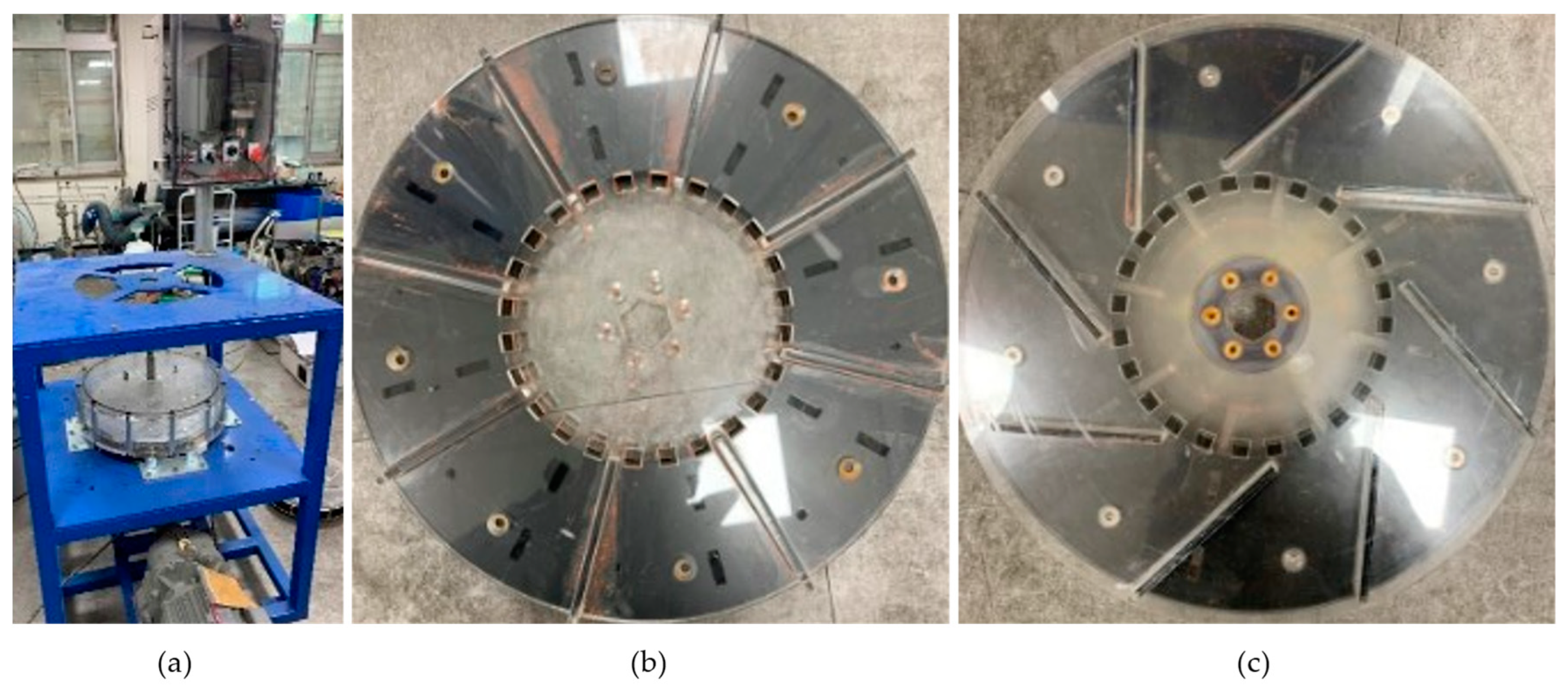
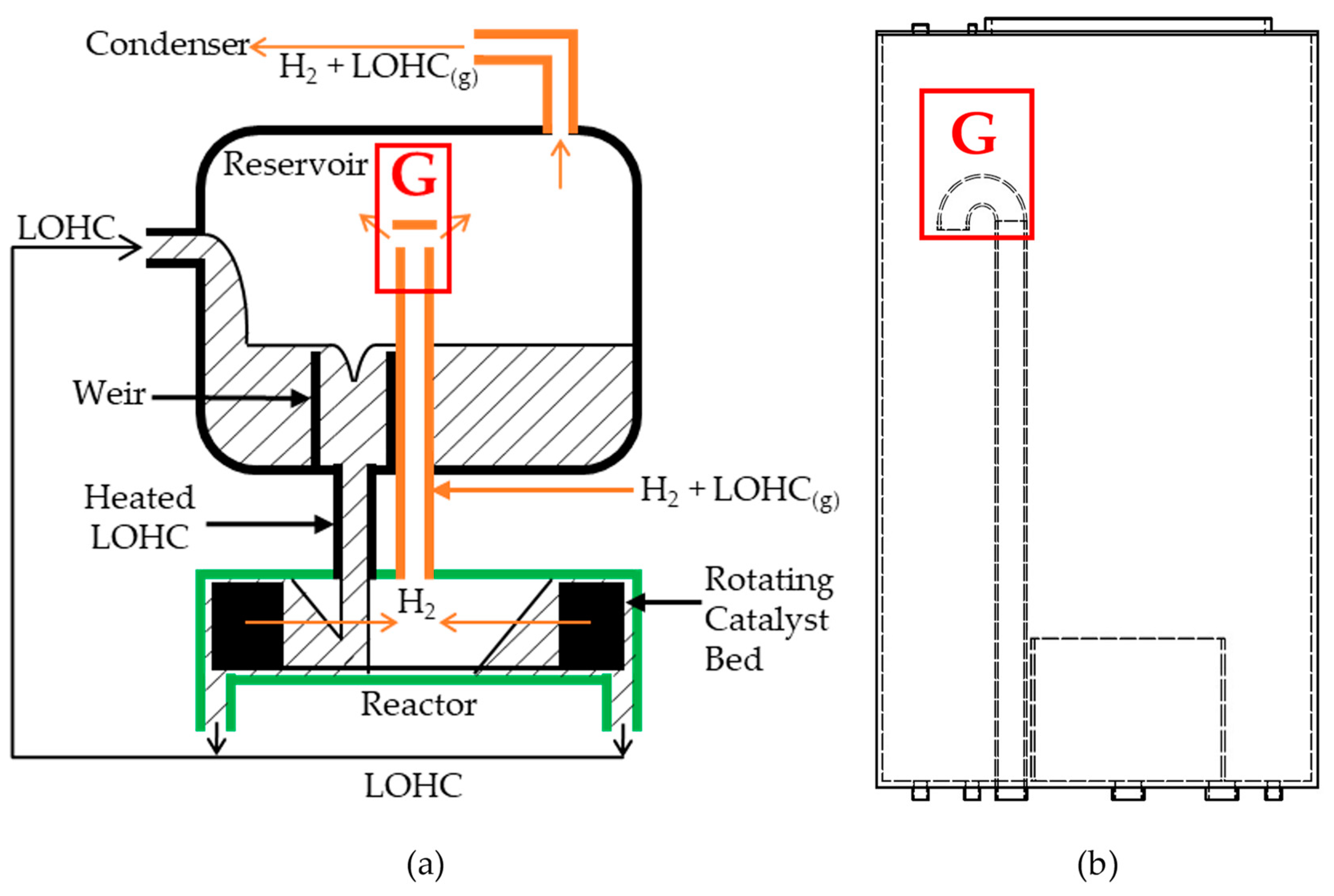
2.1. Reactor System Design Concepts

During LOHC dehydrogenation, the reactor has to manage a large volume of hydrogen precipitation. For example, 1 mL of H18-DBT produces >650 mL of hydrogen gas under ambient conditions. The produced hydrogen displaces the LOHC liquid to reduce the contact area between the LOHC and catalyst. The effective thermal conductivity of the medium also decreases. After the dehydrogenation reaction, small hydrogen bubbles are trapped inside the pores between catalyst particles and cover part of the catalyst surface, reducing the reaction rate in stationary packed bed reactors. The centrifugal force created by the rotating catalyst bed develops a positive radial pressure gradient, facilitating detachment of the hydrogen bubbles from the catalyst surface and buoyancy-driven migration through the porous catalyst bed, so the macroscopic hydrogen production rate is faster than that of a stationary packed bed reactor.
A schematic of the proposed triple-loop dehydrogenation system is displayed in Figure 1. The reservoir is the common part of the reaction, heating, and chilling loops. Through the reaction loop, which is represented by the green solid line box in Figure 1, LOHC liquid circulates between the reactor and the reservoir. The additional pipe (represented by the orange dotted line) delivers a mixture of hydrogen and LOHC vapor from the reactor to the reservoir. Through the heating loop, which is represented by the red dashed line, LOHC liquid circulates between the heater and the reservoir driven by a pump. The heater supplies the reaction enthalpy through a sufficiently large heat exchange area to maintain the heating surface temperature below the thermal degradation temperature. Moreover, the circulation pump provides sufficient flow rate to ensure a sufficiently large convective heat transfer coefficient. Through the chilling loop, which is represented by a blue dash-single dotted line, the mixture of hydrogen and LOHC vapor passes through the condenser. The dry hydrogen gas is then released through the mass flow meter (MFM), and the condensed LOHC is recovered to the reservoir.
Commercially available LOHC material and catalyst pellets were selected. The preliminary experiments were conducted to acquire the knowledge required to design the reactor, reservoir, heater, and condenser.

2.2. LOHC Material and Catalyst

There are several candidate LOHC materials, which share certain attractive characteristics: high hydrogen storage capacity, the ability to undergo repeated hydrogenation and dehydrogenation under specific operating conditions, thermal stability, and low flammability (or non-flammability) [15]. In addition, the U.S. Department of Energy has set a guideline for hydrogen storage capacity at a minimum of 5.5 wt% [16]. The advantages and disadvantages of these LOHC materials have been discussed previously [9,17,18,19,20].
Dibenzyl-toluene (DBT or H0-DBT) was selected as the LOHC-material for the present study. The physical properties of H18-DBT and H0-DBT required for designing the dehydrogenation system have been previously reported [21,22,23]. DBT is most extensively employed for large-scale LOHC technology projects [24] because it is commercially available (Marlotherm SH by Sasol Inc. in Sandton, Republic of South Africa), is non-toxic, and has been widely used as an excellent heat transfer fluid. The LOHC+ material for the present study was prepared in-house by hydrogenating H0-DBT using a 10 L batch reactor under operating conditions of 180 °C and 70 bar [17]. Table 1 presents the physical properties of DBT at representative temperatures. As dehydrogenation progresses and hydrogen is released, the total volume of liquid LOHC within the dehydrogenation system gradually decreases because the density of the LOHC− is relatively higher than that of the LOHC+. At 300 °C, full dehydrogenation results in an approximately 11.5% decrease in volume.
The 0.5 wt% Pt pellet catalyst was purchased from Sigma Aldrich (Saint Louis, MO, USA). Detailed information on the catalyst properties can be found in [25]. The catalyst pellets had a diameter of approximately 3 mm and an apparent density of approximately 540 kg/m3 when loosely packed within the cage. Thus, the required cage volume for 1.5 kg of catalyst was approximately 2.8 L.

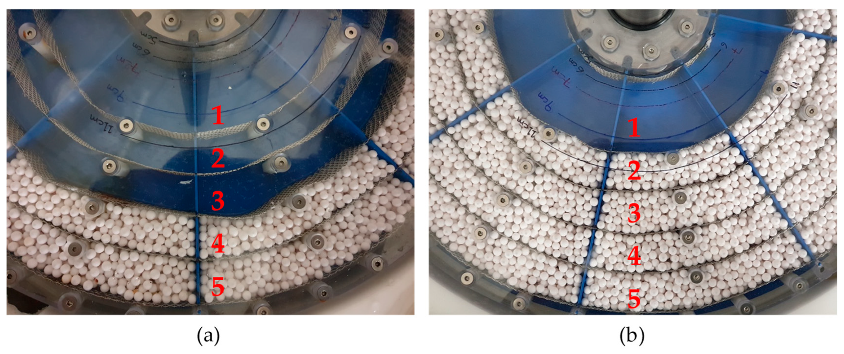
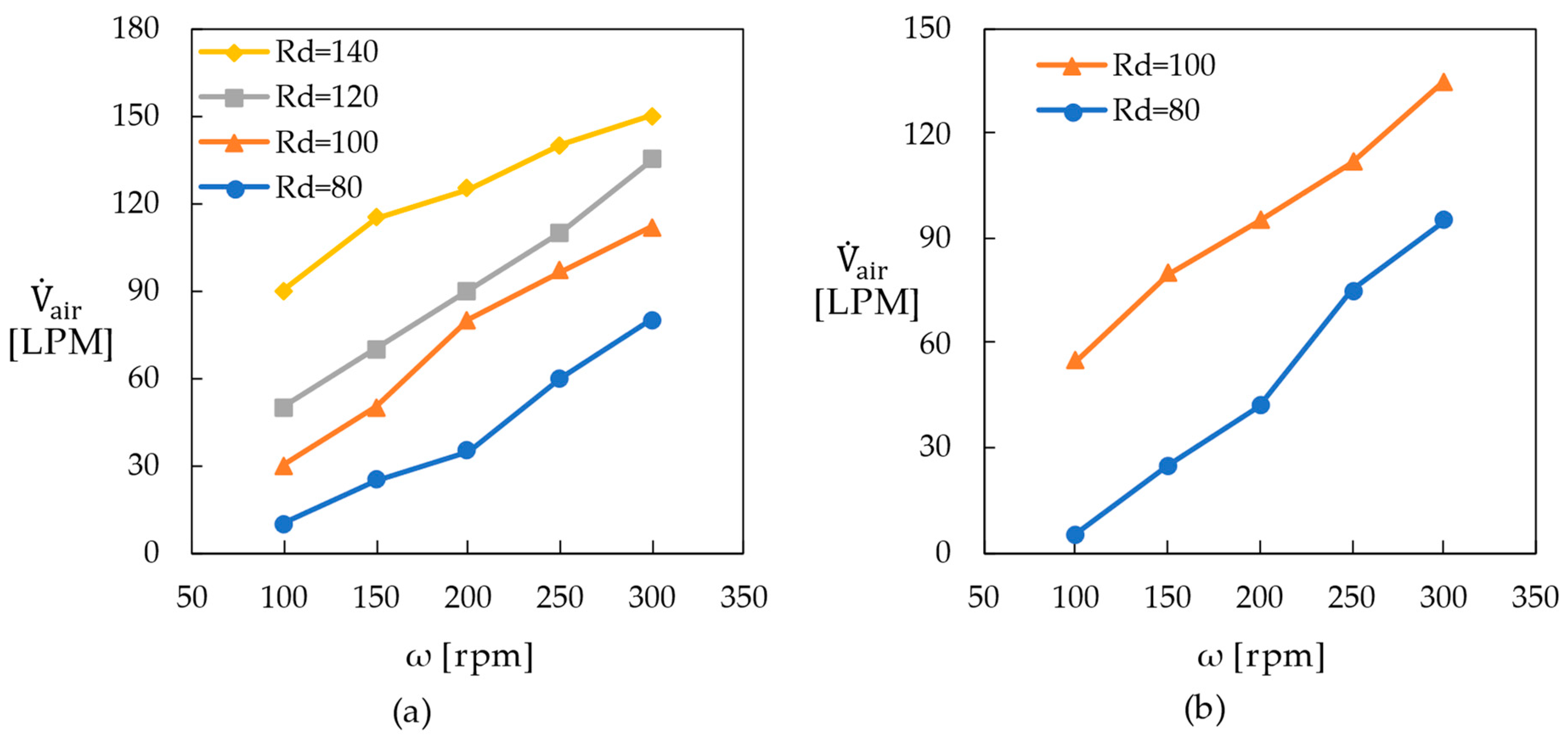
2.3. Gas Infiltration through Catalyst Bed

The gas infiltration experiments were conducted to understand the influence of the rotation speed and the amount of catalyst pellets on the gas isolation ability of the rotating packed bed-type reactor. The experimental results assisted in determining the lower limit of the rotation speed. The LOHC material was mimicked with water, the hydrogen with air, and the catalyst with dummy alumina pellets. The target amount of air infiltration was 33.3 LPM (Liter per minute), which corresponds to an average hydrogen production rate of 2.0 m3H2/h. If 50% dehydrogenation of 25 L of H18-DBT occurred during 500 min, the average hydrogen production rate was approximately 1.0 m3H₂/h.
The gas infiltration experiments were performed within a viewable cylindrical enclosure containing the rotating packed bed. Figure 2 displays a photograph of the test cell equipped with a rotatable synchronous camera, a schematic of the test apparatus, and a photograph of the packed bed partitions. The enclosure had an inner diameter of 380 mm and a height of 67 mm, which was milled from a stainless steel (SUS) square block with a side length of 400 mm. The top end of the SUS block was welded to a 3-mm-thick flange, which was screw-connected to a 20-mm-thick acrylic plate for visibility. The bottom end of the block was welded to a 10-mm-thick stainless plate. One of the sidewalls of the enclosure had an air inlet port through which a specified amount of air was supplied by an air compressor via a flow meter. A pressure tap was installed on another sidewall to measure the pressure difference between the open center and the outer ring of the test enclosure. The rotor was driven by an electric motor, gearbox, and tachometer assembly. The hollow vertical shaft of the rotor had slots near the bottom plate to serve as a water-filling port and was extended above the reactor assembly to support and drive an image-recording camera.
The compact cylindrical cage had an outer diameter of 360 mm and a height of 55 mm and was filled with dummy alumina pellets. The top plate of the cage was 5-mm-thick acrylic plate and the bottom plate was 2-mm-thick SUS plate. The gap between the rotor’s top plate and the top wall of the enclosure was 10 mm, and the rotor’s bottom plate was in close contact with the bottom wall of the enclosure. The eight radial vertical walls of the cage were 2-mm-thick SUS plate. The five concentric vertical walls of the cage were permeable wire mesh, which were placed at radii of 100, 120, 140, 160, and 180 mm. When the cage was partially filled, the radial sections (1, 2, and 3) displayed in Figure 3a were left empty with a porous bed volume of approximately 2210 cc. When the cage was fully filled, only radial section 1 was left empty, as depicted in Figure 3b, with a bed volume of approximately 3870 cc.
To prepare an each test run, the enclosure was filled with water while the cage was rotating at maximum speed until the radius of the dry zone near the rotating axis reached the specified value. Then, the volume flow rate of the air supply was gradually increased until the dry zone radius reached 50 mm. The dry zone was surrounded by an outer ring of a water and air mixture. The maximum airflow rate ( V · air ) and pressure difference (ΔP) were measured. If the air flow rate was further increased above V · air , flushing of the liquid phase was expected.
The values of V · air are represented in Figure 4 for different rotation speeds (ω) and initial dry radii (Rd). For the partially filled cage cases, Rd varied from 80 to 140 mm. As ω increased, V · air increased almost linearly, as depicted in Figure 4a. This was because the radial buoyancy force exerted on the gas phase was strengthened with increased centrifugal force. V · air was larger for a larger Rd because a greater viscous force was required to push the liquid phase toward the center due to the longer radial distance. When ω was 200 rpm (round per minute) and Rd was 100 mm, V · air of the fully filled cage was 95 LPM, which was 15.8% larger than the 80 LPM for the partially filled cage. When ω was 200 rpm and Rd was 80 mm, V · air of the fully filled cage was 42 LPM, which was 16.7% larger than 35 LPM for the partially filled cage. A smaller amount of water was preferred for the gas infiltration. Therefore, the most significant influence was made by the changes in Rd. For both partially and fully filled cages, V · air was more than two times larger if Rd was increased from 80 to 100 mm. The value of ∆P, which corresponds to the pumping head at zero liquid flow rate, was measured at maximum air infiltration. The most significant influence was made by the rotation speed (Figure 5). ∆P increased with ω in a near square relationship. ∆P also increased as the amount of water in the enclosure was increased. The target gas infiltration rate of 2.0 m3H2/h could be achieved at any rotation speed greater than 100 rpm. When the hydrogen production rate decreased during dehydrogenation, the amount of liquid within the reactor automatically increased, resulting in the readjustment of the hydrogen production rate.

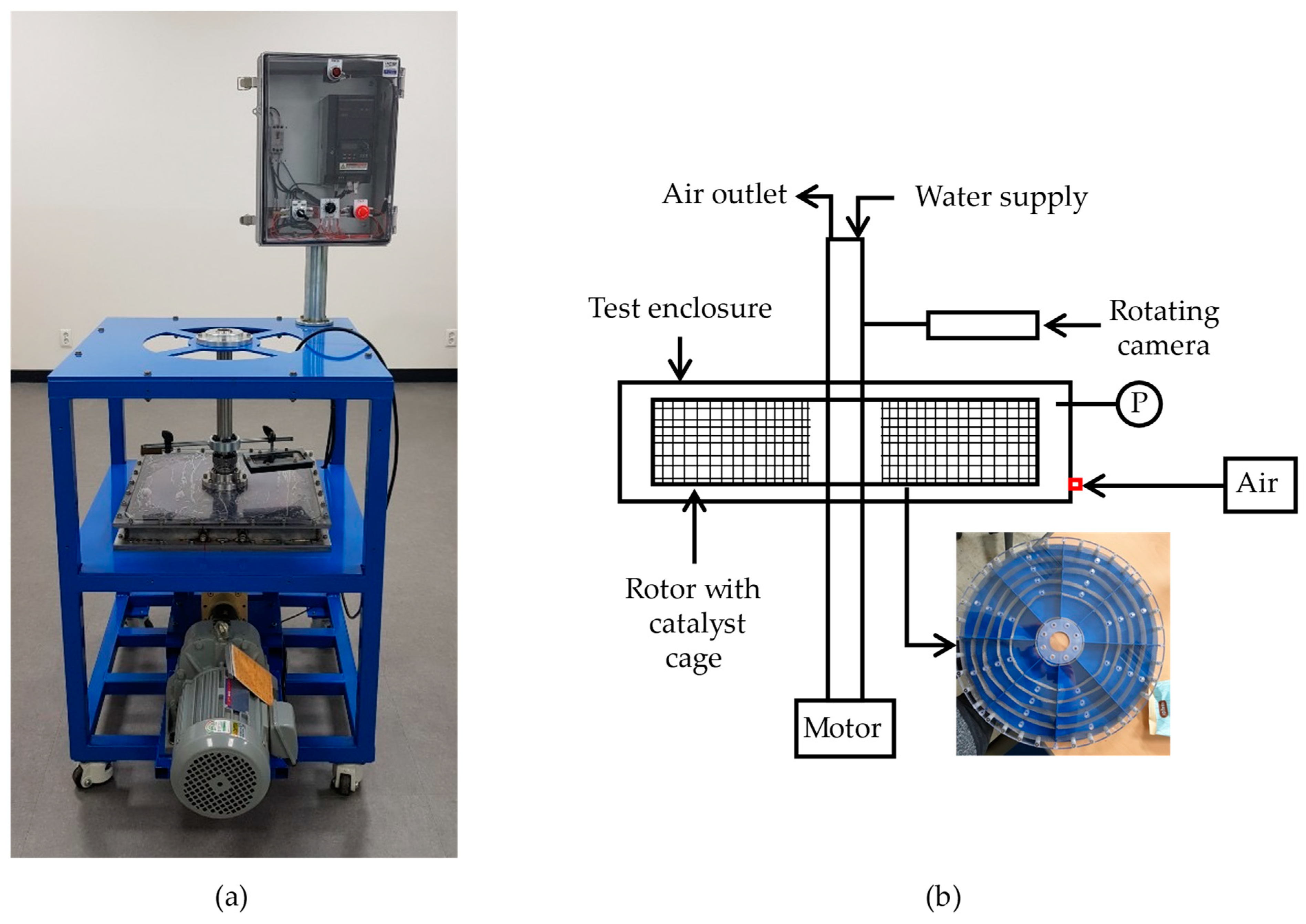
2.4. Flow Visualization Experiment

Flow visualization experiments were conducted to examine the flow structures within the rotating cages. The acquired knowledge aided in determining the configurations of the catalyst pellet pockets. Figure 6a displays a photograph of the apparatus assembly equipped with the rotatable synchronous camera support. The rotation speed could be maintained at a specified value of up to 300 rpm in either the forward or reverse directions.
The test enclosure had an inner diameter of 390 mm and a height of 115 mm. The vertical cylindrical surfaces of the rotor (outer diameter of 370 mm and inner diameter of 180 mm) were metal mesh with 2 mm wire spacing. The top, middle, and bottom horizontal plates of the rotor were 5-mm-thick acrylic plates evenly spaced to form 40-mm-high upper and lower decks. Each deck had eight partitions divided by 3-mm-thick vertical acrylic blades. The rotors having different blade arrangements were fabricated since the plates and blades serve as a pump impeller. The rotor displayed in Figure 6b had radially placed vertical blades in both the upper and lower decks. The rotor blades in the upper deck were twisted clockwise 30°, as displayed in Figure 6c.
The visualized flow structures revealed vigorous secondary recirculation flow within the rotor partitions. The velocity of the rotor’s outer edge was approximately 4.2 m/s at a rotation speed of 200 rpm for the present test enclosure dimensions, while the net radial velocity of the liquid phase was <5.3 cm/s if the liquid flow rate was 4 LPM. The recorded results of flow visualization are provided in Supplementary Materials Video S1. The inward radial flows through the gap between the rotor’s bottom plate and the bottom wall of the enclosure were also observed. The solid contaminants migrated by this flow accumulated around the rotating axis and could damage the bearing.
The lessons learned from the flow visualization experiments employed in the design of the catalyst cage for the dehydrogenation experiment were as follows. Firstly, the bounding surfaces of the rotating catalyst bed, which neighbored the stationary walls of the reactor, needed to be highly permeable to utilize the secondary flow. The catalyst pellets needed to be located within a fairly small effective distance from this permeable wall. Finally, the bottom wall of the rotor should be an impermeable plate extended to the center of rotation and be installed with the narrowest gap with the reactor’s bottom wall.

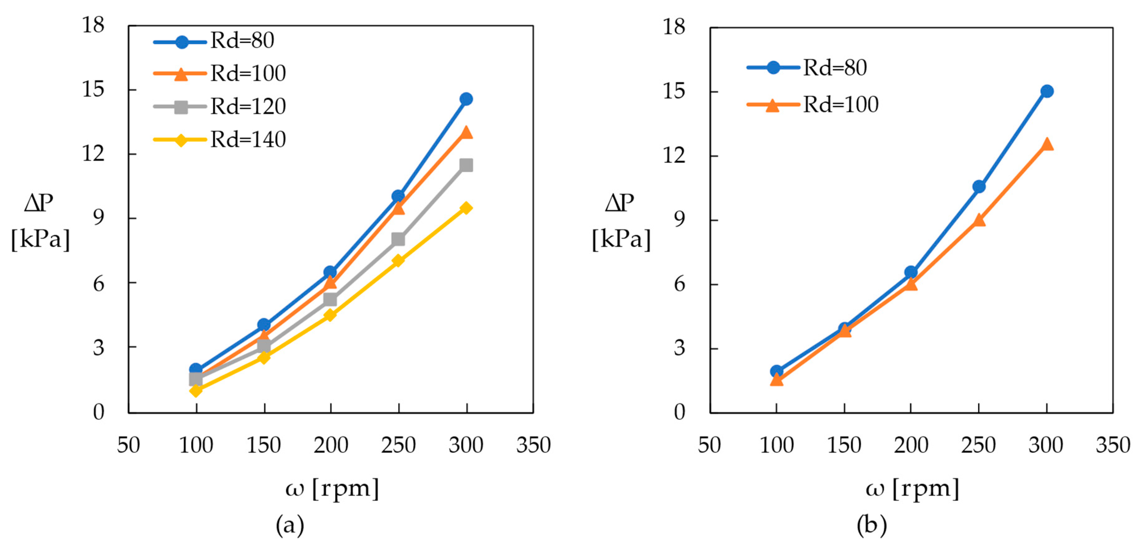
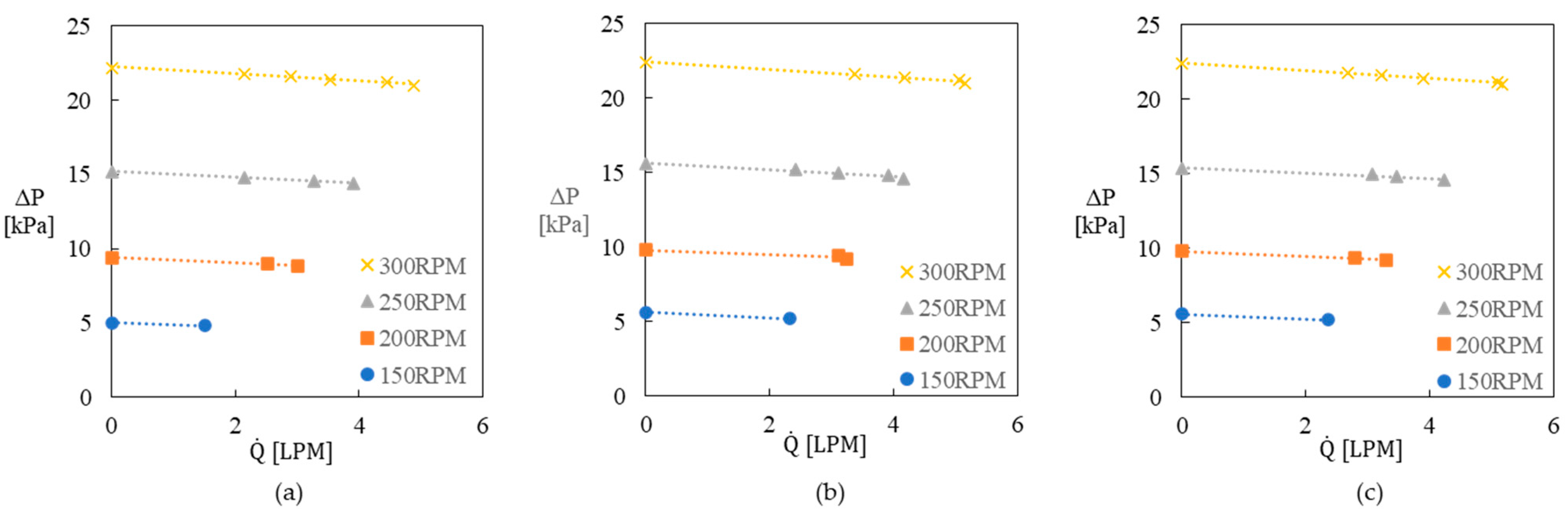
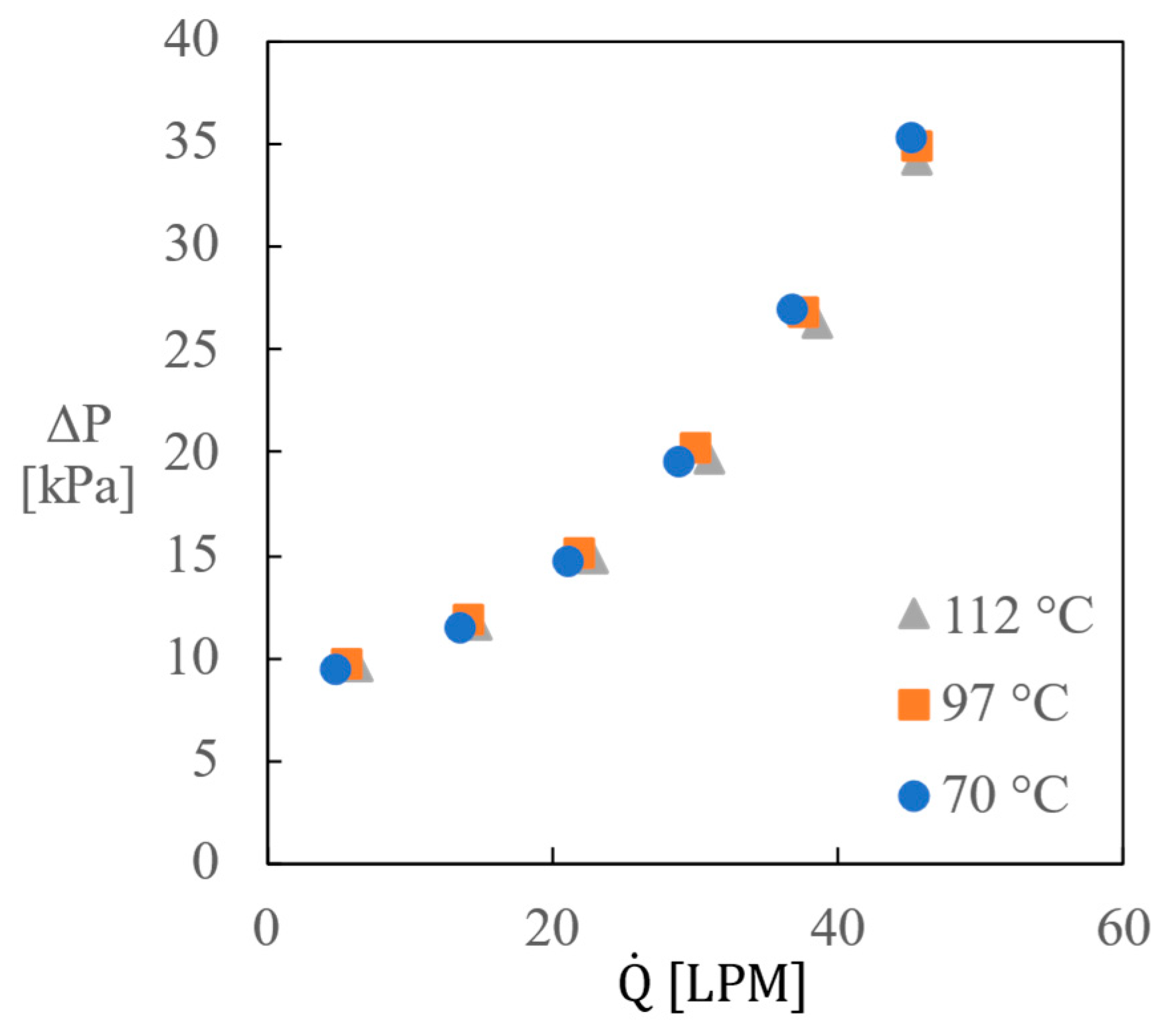
2.5. Reactor Pumping Performance and Heater Flow Resistance

The parts composing the reaction loop in Figure 1 were fabricated, and the liquid pumping capability of the reactor was measured at relatively low temperatures. If the dehydrogenation reactor could provide a sufficient liquid flow rate, the reaction loop could be operated without an additional pump. The dehydrogenation reactor had an inner diameter of 400 mm and a height of 78 mm. The catalyst bed had an outer diameter of 370 mm, an inner diameter of 270 mm, and a height of 60 mm. The reservoir had an inner diameter of 400 mm and a height of 500 mm. The flow control ball valve and flow meter (model HIT-4 from Hoffer Flow Controls, Elizabeth City, NC, USA) were installed downstream of the reactor.
The results of the pumping capability measurements using H0-DBT are displayed in Figure 7. The pressure difference did not change significantly, either with the liquid temperatures of the test range or with flow rates <5 LPM. At a rotation speed of 200 rpm, the reactor provided a flow rate >3.5 LPM despite the flow resistance due to the 12-mm-diameter plumbing around the flow meter. The pressure differences did not differ significantly from the values measured during the gas infiltration experiments (Figure 5). The pressure difference in Figure 5b with maximum air infiltration varied between 12.0 and 13.0 kPa depending on the amount of water within the reactor. The pressure difference for the same rotation speed in Figure 7 was within the range 8.8–9.8 kPa, even for varying flow rates. The densities of H0-DBT (Table 1) for the test range were within 2% of the water density at ambient conditions.
The parts comprising the heating loop in Figure 1 were fabricated and experiments were conducted to measure the flow resistance of the heater. Here, H0-DBT started to flow from the reservoir, then passed through the pump, flow meter, pressure transmitter, and heater before returning to the reservoir. The experimental results are displayed in Figure 8. Sufficient convective heat transfer along the heating surface within the heater was achieved at H0-DBT flow rates >40 LPM. The power required to overcome the flow resistance was calculated to be <19 W. Most of the driving power from the motor was consumed in the form of friction, which was exerted by the high-temperature sealing.

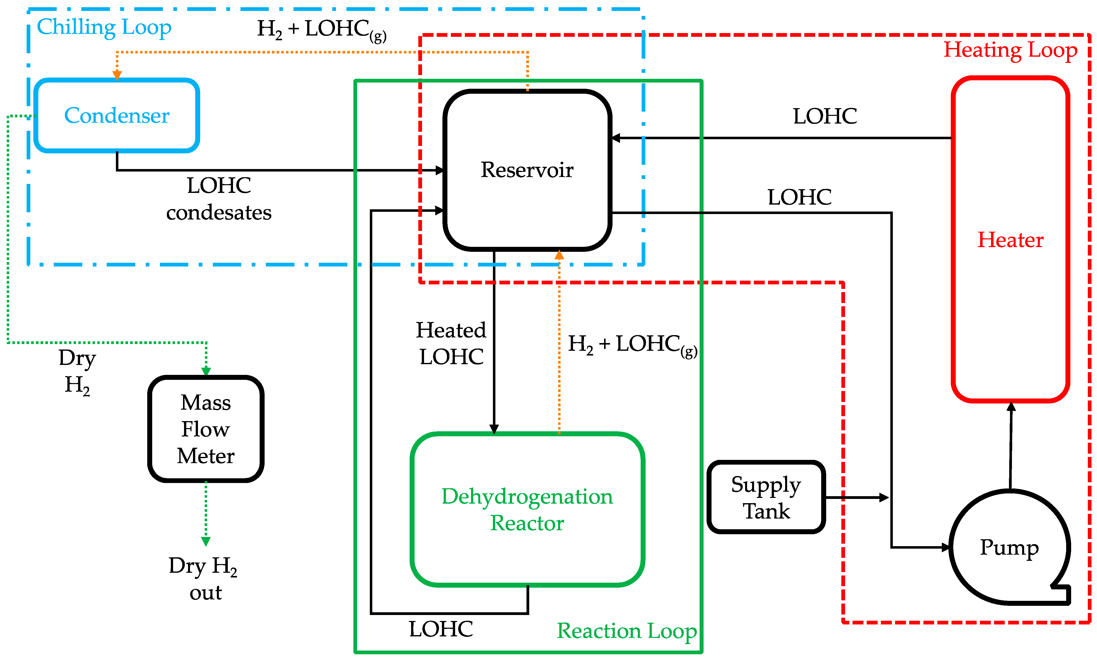
3. Dehydrogenation Experiment

A photograph of the constructed triple-loop dehydrogenation system is displayed in Figure 9. Detailed explanations of the reaction, heating, and chilling loops are provided in the discussion of Figure 1. The inner volumes of the dehydrogenation reactor (Part A in Figure 9) and the reservoir (Part B) were approximately 9.8 and 62.8 L, respectively. The volume of the catalyst cage within the reactor was approximately 3.0 L. Photographs of the reactor’s interior and the catalyst cage are presented in Figure 10. The permeable walls of the catalyst cage were fabricated from perforated stainless steel sheet having a 22.6% open area formed with 2.5-mm-diameter holes spaced 4 mm apart. The pipe that delivered the mixture of hydrogen and LOHC vapor from the top center of the reactor to the reservoir was termed the “flush chimney”. Figure 11 presents a schematic of the reaction loop and the actual shape of the constructed reservoir with the flush chimney (Part G) and a weir. The role of the weir was to prevent the relatively cold and hydrogen-depleted LOHC from directly flowing back into the reactor before being actively mixed with the liquid circulating through the heating loop. The weir could either be omitted or shorter.
The tube and shell type heater (Part C) had a heat exchange area of approximately 3.2 m2 and was formed by the surfaces of 64 stainless steel tubes having an outer diameter of 10 mm and a heating length of 1400 mm. When the total heating rate was 3.2 kW and the flow rate of the LOHC through the heater was 40 LPM, the log mean temperature difference between the heating surface and medium was designed to be <4.0 K. The electric power supplied to the heater was regulated to maintain an outlet medium temperature within 1 K of the specified value. The pump (Part E in Figure 9) circulated liquid DBT through the heating loop and was purchased from Hyup-Jin Chemical Pump Co. (model HJHP 32-160-12) with a displacement volume of 56.3 mL per revolution. The 2.3-kW motor drove the pump and was connected with a water-cooled coupling. All pipes through which the medium was transported between the parts comprising the dehydrogenation system were SUS316 pipes with an inner diameter of 25 mm.
As displayed in Table 1, the vapor pressures of H18-DBT and H0-DBT at 300 °C are approximately 18.9 and 9.6 kPa, respectively. The gas mixture discharged from the reservoir has considerable mole fractions of DBT vapor. The bubble column condenser (Part D), having an inner diameter of 110 mm and a height of 1000 mm, was installed to remove DBT vapor. Water was circulated between an external chiller and the cooling coil to maintain the temperature of the liquid close to 80 °C. The condensed DBT returned to the reservoir. The liquid levels of the reservoir and condenser were the same and were monitored through the glass window along the side of the condenser. An additional heating load was required to balance the enthalpy of evaporation and to reheat the recovered cold DBT. The dried hydrogen was then released via the flow rate measurement device, which was an MFM manufactured by LineTech (Daejeon, Republic of Korea; model: MS2400V, H2 200 SLPM).

4. Results and Discussion

When preparing the dehydrogenation experiment, each loop was purged with 3 bar of N2 at least five times, and the LOHC+ supply tank (Part F in Figure 9) was slightly pressurized to slowly fill the system with H18-DBT having a DoH > 99%. The heating loop was then started to increase the H18-DBT temperature to 300 °C. The reactor was also preheated with 30 cartridge heaters installed along the top and bottom walls. The reactor reached its target temperature in 200 min. The total heating capacities of the reactor and reservoir were 3 and 2 kW, respectively. It took approximately 270 min for the H18-DBT temperature in the heating loop to reach the pre-specified value.
The heating loop was then shut off, and the dehydrogenation reaction was initiated by opening the reaction loop. For the test run discussed in the present report, hydrogen production was made from 26.3 L of H18-DBT by using the reaction loop and the chilling loop only. Heaters installed at reservoir and reactor continuously supplied the heat needed for the dehydrogenation reaction. Some minor degradation of DBT was unavoidable. The amount of H18-DBT initially introduced was 50 L, which was too large to satisfy the goal set for the funded research project: achieve 50% dehydrogenation within 500 min with a LOHC volume larger than 5 L. The liquid volume within the condenser was approximately 5 L, and the liquid volume within the heating loop (except the reservoir) was approximately 18.7 L. A controlled supply of reaction heat was made available to maintain the temperature of the medium leaving the reservoir at the specified value. Intermittent samplings of DBT from the reaction loop were conducted to estimate the transient change in the degree of dehydrogenation (DoD) from the measured refractive indices [26]. The achieved amount of dehydrogenation was 54.2% in 295 min (Figure 12). The accumulated volume of produced hydrogen (VH2) was then calculated by multiplying the initial mole number of the DBT. The average hydrogen production rate during the first hour was 52.6 LPM with 1.5 kg of 0.5 wt% Pt/Al2O3 catalyst. Also experimental results with ideal mixed batch reactor are shown in Figure 12 and Table 2 [11,27]. As shown in Figure 12, the experimental results of the present study with bench-scale process show almost similar reaction rate to ideal mixed batch reactor cases.
Unfortunately, the reaction kinetics of the catalyst pellet employed in the present study were not available. However, a screening test of commercial catalysts for the dehydrogenation of H18-DBT has been conducted [11]. The performance of the 0.5 wt% Pt/Al2O3 catalyst supplied by Hydrogenious Technologies was approximately 25% faster compared to that of the 5.0 wt% Pt/Al2O3 catalyst supplied by Sigma-Aldrich. A comparison with the predictions made with the empirical reaction kinetics in Equation (1) is provided in Figure 12. The reaction rates in Equation (1) were measured with a small-scale plug flow dehydrogenation reactor with 0.1–1.0 g of 5.0 wt% Pt/Al2O3 catalyst [17]. VH2 was calculated using Equation (2), which is also borrowed from the same report.
r = 5.4 × 10 11 e 171.72 R T C H 18 D B T 2.395 ± 0.045  
W c a t a l y s t F H 18 D B T = 1 X o u t d X H 18 D B T r
In the above equations,
C H 18 D B T mol/LMolar concentration of H18-DBT
F H 18 D B T mol/sInlet molar flow of H18-DBT
r mol/kg s Reaction rate
W c a t a l y s t kgWeight of catalyst
X H 18 D B T Fractional conversion of H18-DBT.
The gas flow rates downstream of the condenser were measured with a mass flow meter. The transient MFM readings during the first hour are displayed in Figure 13. When compared with the average hydrogen production rate estimated from refractive index measurements, the MFM values were noticeably higher, indicating that the LOHC vapor was not adequately removed from the gas mixture produced by the reactor with the bubble column condenser employed in the present study. Moreover, the MFM measurement results could not be trusted because the MFM readings were stopped due to device failure after 75 min of dehydrogenation.

5. Conclusions

In this paper, a triple-loop dehydrogenation system based on a centrifugal convection reactor was proposed to improve the dehydrogenation speed of LOHC technology. From three preliminary experiments and a trial run of the constructed dehydrogenation system, the following conclusions were obtained:
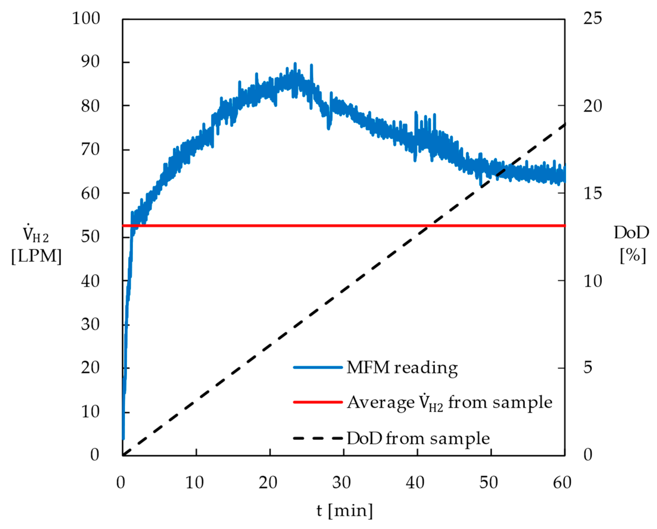
  • The dehydrogenation reactor developed in this study demonstrated superior performance compared to conventional fixed-bed or batch reactors, primarily due to the efficient separation of hydrogen bubbles from the catalyst surface. Using 1.5 kg of commercially available 0.5 wt% Pt catalyst and 26.3 L of perhydro-DBT, the degree of dehydrogenation reached 54.2% in 295 min.
  • The average hydrogen production rate during the first hour was measured at 52.6 LPM, which was approximately 148% of the predicted value based on the reaction kinetics of the 5.0 wt% Pt catalyst from Sigma-Aldrich®.
  • The preliminary gas infiltration experiments indicated that the proposed reactor isolated 42–95 LPM of hydrogen production at a rotation speed of 200 rpm when the catalyst volume was 2.8 L. The amount of liquid within the reactor was automatically adjusted according to changes in the hydrogen production rate.
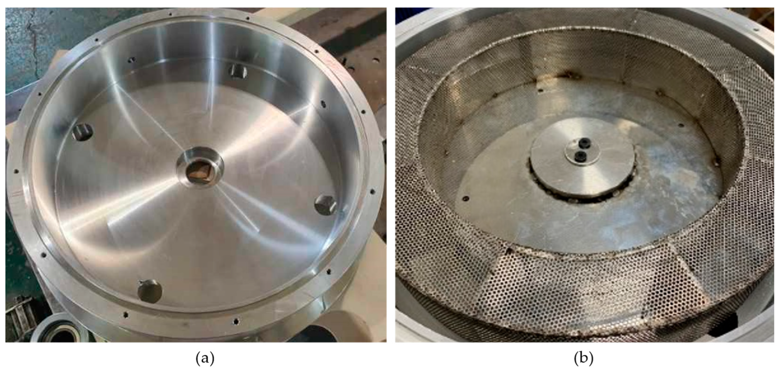
  • The bounding surfaces of the rotating catalyst bed neighboring the stationary walls of the reactor needed to be highly permeable to utilize the secondary flow. Moreover, the catalyst pellets needed to be located within a small effective distance from this permeable wall. Finally, the bottom wall of the rotor must be an impermeable plate that extends to the center of rotation and be installed with the narrowest gap from the reactor’s bottom wall.
  • The flow through the reaction loop could be driven by the pumping capacity of the reactor for rotation speeds > 200 rpm. However, the amount of convective heat transfer along the heating surface sufficient to avoid thermal degradation must be accomplished by employing a separate heating loop with an adequately sized pump.
  • If LOHC vapor was not adequately removed from the gas mixture produced by the reactor, the MFM measurement results could not be trusted.
The following future research directions were identified:
  • The degradation characteristics of the LOHC material need to be studied to provide the criteria required in the design of the heating mechanism.
  • A condenser that effectively removes LOHC vapor from the produced hydrogen without any accompanying significant flow resistance needs to be developed.

Supplementary Materials

The following supporting information can be downloaded at: https://youtu.be/n8eK_T0Duc4 (accessed on 1 July 2024), Video S1: Flow visualization of secondary circulation within a rotating partition.

Author Contributions

Conceptualization, S.L. and M.H.S.; experiment implementation including design and assembly of apparatus, J.L. and M.U.; data curation, S.P.; writing—original draft preparation, J.L., M.U. and S.P.; writing—review and editing, S.L. and M.H.S. All authors have read and agreed to the published version of the manuscript.

Funding

The authors are thankful to human resources development project of the Korea Institute of Energy Technology Evaluation and Planning (KETEP) for the support grant funded by the Korea government Ministry of Trade, Industry and Energy under the project titled Middle market enterprise specialized human resources development for residential and commercial fuel cell, numbered: 20224000000580. They are also thankful for the support given by the Dongguk University Research Fund of 2023.

Institutional Review Board Statement

Not applicable.

Informed Consent Statement

Not applicable.

Data Availability Statement

The original contributions presented in the study are included in the article and Supplementary Materials, further inquiries can be directed to the corresponding authors.

Conflicts of Interest

Author Muhammad Usman was employed by the company SNAM Automobiles Industries Co. The remaining authors declare that the research was conducted in the absence of any commercial or financial relationships that could be construed as a potential conflict of interest.

References

  1. Kothari, R.; Buddhi, D.; Sawhney, R.L. Comparison of Environmental and Economic Aspects of Various Hydrogen Production Methods. Renew. Sustain. Energy Rev. 2008, 12, 553–563. [Google Scholar] [CrossRef]
  2. Züttel, A. Hydrogen Storage Methods. Naturwissenschaften 2004, 91, 157–172. [Google Scholar] [CrossRef] [PubMed]
  3. Niaz, S.; Manzoor, T.; Pandith, A.H. Hydrogen Storage: Materials, Methods and Perspectives. Renew. Sustain. Energy Rev. 2015, 50, 457–469. [Google Scholar] [CrossRef]
  4. Preuster, P.; Papp, C.; Wasserscheid, P. Liquid Organic Hydrogen Carriers (LOHCs): Toward a Hydrogen-Free Hydrogen Economy. Acc. Chem. Res. 2017, 50, 74–85. [Google Scholar] [CrossRef] [PubMed]
  5. Teichmann, D.; Arlt, W.; Wasserscheid, P.; Freymann, R. A Future Energy Supply Based on Liquid Organic Hydrogen Carriers (LOHC). Energy Environ. Sci. 2011, 4, 2767. [Google Scholar] [CrossRef]
  6. Niermann, M.; Beckendorff, A.; Kaltschmitt, M.; Bonhoff, K. Liquid Organic Hydrogen Carrier (LOHC)—Assessment Based on Chemical and Economic Properties. Int. J. Hydrogen Energy 2019, 44, 6631–6654. [Google Scholar] [CrossRef]
  7. Modisha, P.M.; Ouma, C.N.M.; Garidzirai, R.; Wasserscheid, P.; Bessarabov, D. The Prospect of Hydrogen Storage Using Liquid Organic Hydrogen Carriers. Energy Fuels 2019, 33, 2778–2796. [Google Scholar] [CrossRef]
  8. Zhu, Q.-L.; Xu, Q. Liquid Organic and Inorganic Chemical Hydrides for High-Capacity Hydrogen Storage. Energy Environ. Sci. 2015, 8, 478–512. [Google Scholar] [CrossRef]
  9. Naseem, M.; Usman, M.; Lee, S. A Parametric Study of Dehydrogenation of Various Liquid Organic Hydrogen Carrier (LOHC) Materials and Its Application to Methanation Process. Int. J. Hydrogen Energy 2021, 46, 4100–4115. [Google Scholar] [CrossRef]
  10. Bollmann, J.; Schmidt, N.; Beck, D.; Preuster, P.; Zigan, L.; Wasserscheid, P.; Will, S. A Path to a Dynamic Hydrogen Storage System Using a Liquid Organic Hydrogen Carrier (LOHC): Burner-Based Direct Heating of the Dehydrogenation Unit. Int. J. Hydrogen Energy 2023, 48, 1011–1023. [Google Scholar] [CrossRef]
  11. Brückner, N.; Obesser, K.; Bösmann, A.; Teichmann, D.; Arlt, W.; Dungs, J.; Wasserscheid, P. Evaluation of Industrially Applied Heat-Transfer Fluids as Liquid Organic Hydrogen Carrier Systems. ChemSusChem 2014, 7, 229–235. [Google Scholar] [CrossRef] [PubMed]
  12. Sekine, Y.; Higo, T. Recent Trends on the Dehydrogenation Catalysis of Liquid Organic Hydrogen Carrier (LOHC): A Review. Top. Catal. 2021, 64, 470–480. [Google Scholar] [CrossRef]
  13. Amende, M.; Gleichweit, C.; Schernich, S.; Höfert, O.; Lorenz, M.P.A.; Zhao, W.; Koch, M.; Obesser, K.; Papp, C.; Wasserscheid, P.; et al. Size and Structure Effects Controlling the Stability of the Liquid Organic Hydrogen Carrier Dodecahydro-N-Ethylcarbazole during Dehydrogenation over Pt Model Catalysts. J. Phys. Chem. Lett. 2014, 5, 1498–1504. [Google Scholar] [CrossRef] [PubMed]
  14. Gianotti, E.; Taillades-Jacquin, M.; Rozière, J.; Jones, D.J. High-Purity Hydrogen Generation via Dehydrogenation of Organic Carriers: A Review on the Catalytic Process. ACS Catal. 2018, 8, 4660–4680. [Google Scholar] [CrossRef]
  15. Markiewicz, M.; Zhang, Y.Q.; Bösmann, A.; Brückner, N.; Thöming, J.; Wasserscheid, P.; Stolte, S. Environmental and Health Impact Assessment of Liquid Organic Hydrogen Carrier (LOHC) Systems—Challenges and Preliminary Results. Energy Environ. Sci. 2015, 8, 1035–1045. [Google Scholar] [CrossRef]
  16. Energy Efficiency & Renewable Energy. Multiyear Research, Development, and Demonstration Plan; Department of Energy, United States: Washington, DC, USA, 2012; p. 1219578. [CrossRef]
  17. Park, S.; Naseem, M.; Lee, S. Experimental Assessment of Perhydro-Dibenzyltoluene Dehydrogenation Reaction Kinetics in a Continuous Flow System for Stable Hydrogen Supply. Materials 2021, 14, 7613. [Google Scholar] [CrossRef] [PubMed]
  18. Hurskainen, M.; Ihonen, J. Techno-Economic Feasibility of Road Transport of Hydrogen Using Liquid Organic Hydrogen Carriers. Int. J. Hydrogen Energy 2020, 45, 32098–32112. [Google Scholar] [CrossRef]
  19. Pawelczyk, E.; Łukasik, N.; Wysocka, I.; Rogala, A.; Gębicki, J. Recent Progress on Hydrogen Storage and Production Using Chemical Hydrogen Carriers. Energies 2022, 15, 4964. [Google Scholar] [CrossRef]
  20. Nielsen, M.; Alberico, E.; Baumann, W.; Drexler, H.-J.; Junge, H.; Gladiali, S.; Beller, M. Low-Temperature Aqueous-Phase Methanol Dehydrogenation to Hydrogen and Carbon Dioxide. Nature 2013, 495, 85–89. [Google Scholar] [CrossRef]
  21. Müller, K.; Stark, K.; Emel’yanenko, V.N.; Varfolomeev, M.A.; Zaitsau, D.H.; Shoifet, E.; Schick, C.; Verevkin, S.P.; Arlt, W. Liquid Organic Hydrogen Carriers: Thermophysical and Thermochemical Studies of Benzyl- and Dibenzyl-Toluene Derivatives. Ind. Eng. Chem. Res. 2015, 54, 7967–7976. [Google Scholar] [CrossRef]
  22. Aslam, R.; Müller, K.; Müller, M.; Koch, M.; Wasserscheid, P.; Arlt, W. Measurement of Hydrogen Solubility in Potential Liquid Organic Hydrogen Carriers. J. Chem. Eng. Data 2016, 61, 643–649. [Google Scholar] [CrossRef]
  23. Jorschick, H.; Geißelbrecht, M.; Eßl, M.; Preuster, P.; Bösmann, A.; Wasserscheid, P. Benzyltoluene/Dibenzyltoluene-Based Mixtures as Suitable Liquid Organic Hydrogen Carrier Systems for Low Temperature Applications. Int. J. Hydrogen Energy 2020, 45, 14897–14906. [Google Scholar] [CrossRef]
  24. Li, H.; Zhang, X.; Zhang, C.; Ding, Z.; Jin, X. Application and Analysis of Liquid Organic Hydrogen Carrier (LOHC) Technology in Practical Projects. Energies 2024, 17, 1940. [Google Scholar] [CrossRef]
  25. Kwak, Y.; Moon, S.; Ahn, C.; Kim, A.-R.; Park, Y.; Kim, Y.; Sohn, H.; Jeong, H.; Nam, S.W.; Yoon, C.W.; et al. Effect of the Support Properties in Dehydrogenation of Biphenyl-Based Eutectic Mixture as Liquid Organic Hydrogen Carrier (LOHC) over Pt/Al2O3 Catalysts. Fuel 2021, 284, 119285. [Google Scholar] [CrossRef]
  26. Müller, K.; Aslam, R.; Fischer, A.; Stark, K.; Wasserscheid, P.; Arlt, W. Experimental Assessment of the Degree of Hydrogen Loading for the Dibenzyl Toluene Based LOHC System. Int. J. Hydrogen Energy 2016, 41, 22097–22103. [Google Scholar] [CrossRef]
  27. Jorschick, H.; Preuster, P.; Dürr, S.; Seidel, A.; Müller, K.; Bösmann, A.; Wasserscheid, P. Hydrogen Storage Using a Hot Pressure Swing Reactor. Energy Environ. Sci. 2017, 10, 1652–1659. [Google Scholar] [CrossRef]
Figure 1. Schematic of the triple loop dehydrogenation system.
Applsci 14 05803 g001
Figure 2. (a) Photograph of the gas infiltration experiment assembly. (b) Schematic of the test apparatus with a photograph of pellet cage partitions.
Applsci 14 05803 g002
Figure 3. Photographs of (a) partially filled and (b) fully filled pellet cage.
Applsci 14 05803 g003
Figure 4. Maximum air infiltration rate through reactors with (a) partially filled pellet cage, and (b) fully filled pellet cage (LPM, liter per minute).
Applsci 14 05803 g004
Figure 5. Radial pressure difference within the reactor with (a) partially filled pellet cage, and (b) fully filled pellet cage.
Applsci 14 05803 g005
Figure 6. Photographs of (a) flow visualization apparatus assembly, (b) a rotor with radial blades in both upper and lower decks, and (c) a rotor with twisted blades in upper deck.
Applsci 14 05803 g006
Figure 7. Pressure difference and maximum flow rate established by reactor at H0-DBT temperatures of (a) 70 °C; (b) 97 °C; (c) 112 °C.
Applsci 14 05803 g007
Figure 8. Flow resistance of heater at H0-DBT temperatures.
Applsci 14 05803 g008
Figure 9. Photograph of constructed dehydrogenation system. A: Dehydrogenation Reactor; B: Reservoir; C: Heater; D: Condenser; E: Pump; F: Supply tank.
Applsci 14 05803 g009
Figure 10. Photographs of (a) dehydrogenation reactor interior and (b) catalyst cage partially made with perforated stainless steel sheet.
Applsci 14 05803 g010
Figure 11. (a) The schematic of reaction loop; (b) actual shape of the constructed reservoir with a flush chimney, Part “G”, and a weir.
Applsci 14 05803 g011
Figure 12. Comparison of experimental results with previous studies [11,27]. The accumulated volume of produced hydrogen (VH2) is for the present study and the prediction with Equation (1) only.
Applsci 14 05803 g012
Figure 13. Measured hydrogen flow rate with mass flow meter compared.
Applsci 14 05803 g013
Table 1. Properties of perhydro-DBT and DBT according to experimental temperatures [9,23].
Experiment
Temperature (°C)
H18-DBTH0-DBT
Density (kg/m3)Viscosity (mPa·s)Vapor Pressure
(Pa)
Density (kg/m3)Viscosity (mPa·s)Vapor Pressure
(Pa)
20913.4252.34.22 × 10−41104444.189.91 × 10−5
70881.515.969.91 × 10−1710086.4575.08 × 10−2
97864.26.4266.61 × 10−10989.13.2724.95 × 10−1
112854.74.4033.99 × 10−7978.32.4281.61 × 100
300734.62.3991.89 × 104843.90.79119.56 × 103
Table 2. Reactor type, catalyst and H18-DBT amount of experimental results in Figure 12 [11,27].
StudyReactor TypeCatalystH18-DBT CapacityResult
Jorschick et al. [27]Batch0.3 wt% Pt1.1 molDoD = 40% in 192 min
Brückner et al. [11]Batch0.5 wt% Pt0.1 molDoD = 40% in 120 min 1
DoD = 51% in 210 min 2
Present studyBatch0.5 wt% Pt82.8 molDoD = 54% in 295 min
1 0.1 mol% Pt applied as 0.5 wt% Pt/Al2O3. 2 0.15 mol% Pt applied as 0.5 wt% Pt/Al2O3.
Disclaimer/Publisher’s Note: The statements, opinions and data contained in all publications are solely those of the individual author(s) and contributor(s) and not of MDPI and/or the editor(s). MDPI and/or the editor(s) disclaim responsibility for any injury to people or property resulting from any ideas, methods, instructions or products referred to in the content.

