Article

Hydraulic Expansion Techniques for Fracture-Cavity Carbonate Rock with Field Applications

1
Engineering Institute, China University of Petroleum (Beijing), Karamay 834000, China
2
Xinjiang Key Laboratory of Multi-Medium Pipeline Safety Transportation, Urumqi 830000, China
*
Author to whom correspondence should be addressed.
Appl. Sci. 2024, 14(13), 5851; https://doi.org/10.3390/app14135851
Submission received: 4 February 2024 / Revised: 10 April 2024 / Accepted: 24 June 2024 / Published: 4 July 2024
(This article belongs to the Topic Petroleum and Gas Engineering)

Abstract

:
Fracture-cavity carbonate reservoirs provide a large area, fracture development, high productivity, long stable production time, and other characteristics. However, after long-term exploitation, the lack of energy in the formation leads to a rapid decrease in production, and the water content in crude oil steadily increases, thereby disrupting normal production. To recover normal production, it is necessary to connect the cracks and pores that have not been affected during the original production, so as to allow the crude oil inside to enter the production cracks and replenish energy through methods such as hydraulic expansion of fracture-cavity carbonate rock. Accordingly, we propose hydraulic expansion techniques based on the following four processes for implementation: (1) applying high pressure to prevent a nearby fracture network from opening the seam, (2) connecting a distant fracture-cavity body, (3) breaking through the clay filling section of a natural fracture network, and (4) constructing an injection production well pattern for accelerating injection and producing diversion. Hydraulic fracturing involves closing or partially closing the original high-permeability channels, which usually produce a large amount of water, while opening previously unaffected areas through high pressure to increase crude oil production. We also introduce two composite techniques: (1) temporary plugging of the main deep fractures, followed by hydraulic expansion; and (2) capacity expansion and acidification/pressure processes. Hydraulic expansion allowed us to recover and supplement the formation energy and efficiently increase production. We tested various wells, achieving an effective hydraulic expansion rate of up to 85%. In addition, the productivity of conventional water injection and hydraulic expansion after on-site construction was compared for one well, clearly indicating the effectiveness of water injection and the remarkable crude oil increase after hydraulic expansion.

1. Introduction

The global carbonate strata contain abundant oil and gas resources, making them the most important aspect of oil and gas exploration and development. With continued exploration and development, several fracture-cavity carbonate reservoirs have recently been found in deep and ultra-deep layers. In China, the Tahe, Tazhong, and Harahatang oilfields in the Tarim Basin are the main oilfields, and their activity often appears in seismic exploration images [1,2,3].
Owing to their strong heterogeneity, methods such as water injection and acid fracturing fail to increase production [4,5,6,7]. Fractured-vug carbonate reservoirs are often composed of sheet-like local areas [8]. As shown in Figure 1, geological prediction data indicate the presence of cavity-side holes around drilled wells, with unconnected reservoirs of different scales near or far away from the main reservoir [9]. To exploit such reservoirs with irregular distributions and different sizes while considering economic viability, new wells are rarely drilled. Instead, various processes are used to connect these reservoirs with existing drilled reservoirs for exploitation. For instance, acid fracturing is used to transform or exploit this type of reservoir. However, due to the strong heterogeneity of fracture-cavity carbonate reservoirs, acid preferentially results in high-permeability or fracture-developed areas during injection, while low-permeability and seriously polluted reservoirs remain unaffected. Moreover, acid fracturing is not applicable to distant fracture-cavity reservoirs [10]. Alternatively, the main fractures in a reservoir can be exploited to recover the remaining oil around or between wells through high-pressure water injection and supersaturation expansion. These methods are collectively known as hydraulic expansion.
In this paper, we present and propose various problems, along with measures to address them by implementing volume fracturing. These problems include (1) multiple sets of fracture and pore bodies developed around the well but failing to deliver proper oil and gas production, (2) fractures blocked by mud filling, (3) constant volume characteristics and multiple rounds of water injection with adverse effects, and (4) wells with ineffective fluid supply after pre-injection fracturing. These problems are common and should be properly handled to increase production.

2. Proposed Method for Increased Production Using Hydraulic Expansion

Hydraulic expansion involves injecting water into a formation under high pressure and high displacement. The injected water is used as the energy carrier to build a high-pressure environment in the bottom hole, reopen closed fractures around the wellbore, and break through the barrier (constant volume interface) of isolated fractures and holes around a well [11,12].
According to the geological conditions of different types of wells and the distribution of adjacent wells, we devised various production-increasing processes, as described in Figure 2. In the face of wells around multiple sets of developed fracture-cavity bodies, we apply high pressure to prevent a nearby fracture network from opening the seam connecting a distant fracture-cavity reservoir. For a fault-controlled karst with clay filling, we break through the clay filling section of the natural fracture network to construct an injection production well pattern. As a well with constant volume and multiple rounds of water injection shows unfavorable production, we increase the injection rate to produce diversion and spread to remaining unswept fracture areas. For wells showing insufficient fluid supply after pre-acidification fracturing, we activate a closed or partially closed original high-permeability channel by applying high pressure. We also propose two composite processing methods, namely, using a composite blocking and expansion process to prevent the injected water from seeping down along large fault zones, and using an expansion and acidification/acid fracturing composite process to increase the production of these wells without an obvious communication between pre-acidification and fracturing.

2.1. High Pressure to Prevent Nearby Fracture Network from Opening Seams Connecting Distant Fracture-Cavity Reservoirs

In fracture-cavity carbonate rocks, a typical reservoir is characterized by the development of faults in the well area, and good reservoirs are located around the well. However, owing to insufficient formation energy, water injection in the adjacent well fails to replace oil, the pressure drops sharply, and the fractures close. For this type of reservoir, we propose hydraulic expansion using high pressure to prevent the nearby fracture network from opening the seam that connects the distant fracture-cavity reservoir [13].
As a representative example, consider expansion well 1 with a drilling completion depth of 5830 m, vertical depth of 5795.46 m, and average amplitude change rate between 0 ms and 40 ms. The well is located in a positive fold area and contains developed faults. The west and northwest directions indicate good reservoirs. However, regarding development, the well mainly uses the energy body of an adjacent well, and the water injection pressure is constant, leading to a production decline over the years [14]. Calculations indicate a formation extension pressure of approximately 85 MPa, while during construction an actual bottom hole pressure of 94 MPa, maximum pressure of 39 MPa, displacement of 60 m3/h, and water injection of 3534 m3 were observed, reaching the formation opening pressure. Therefore, high pressure is used to hold down the nearby fracture network to open the seam, thus connecting the distant fracture-cavity reservoir. The construction curve in Figure 3 shows clear pressure fluctuations under the same displacement, indicating the connection of the reservoir around the well. In addition, the pressure is properly transmitted to the far end, demonstrating the feasibility of the proposed stimulation technique.

2.2. Break through the Clay Filling Section of the Natural Fracture Network to Construct the Injection Production Well Pattern

A cavity may appear next to another one in a fracture-cavity carbonate reservoir. In addition, the cavity has an adequate geological connection foundation, and all of the reservoirs are large fracture-cavity bodies [15,16]. However, owing to the development of mud in the communication channels between reservoirs, the seepage channels are blocked, resulting in low yields. For this type of fracture-cavity reservoir, we propose hydraulic expansion that increases the water injection volume and breaks through the muddy filling section of the natural fracture network to construct an injection production well network.
Consider expansion well 2, located in the secondary fracture zone of T738, a well group that extends from east to west as a fracture. Regarding the amplitude change rate, the inter-well reservoir is well developed, and the geological connection foundation is adequate. Dynamic analysis data reveal that the adjacent well did not respond to water injection of the single well in an early stage under high water injection pressure and with a tight periphery. Static geological data show that the connection foundation is adequate and that expansion well 2 and well 202 are large fracture caverns. Consequently, the static and dynamic data are inconsistent, and it is suspected that clay filling takes place in the channel, consequently blocking the seepage channel [17]. In this case, hydraulic expansion can be used to increase the injection force on the channel and break through the seepage barrier. We increased the pressure and injected 4212 m3 of liquid into well 2 to break through the clay filling zone. As a result, the casing pressure and fluid production of adjacent wells 201 and 202 increased, crude oil production increased by 317 t, and the recoverable crude oil increased by 3000 t, demonstrating the effectiveness of this technique to increase production, as shown in Figure 4.

2.3. Increased Injection Rate to Produce Diversion and Spread to Remaining Unswept Fracture Areas

Tight reservoirs may be present in the periphery of fracture-cavity carbonate reservoirs, but they exhibit very low permeability and poor reservoir communication. In this type of reservoir fracturing construction, even if the maximum available construction pressure is applied, communication to the main fracture cannot be achieved. Alternatively, we propose continuing to inject water after the original reservoir reaches saturation and increasing the injection rate, such that the injected water diverges, sweeps to other fracture channels, and increases the permeability to ultimately increase production [18].
Expansion well 3 is located on the edge of the subsidiary fracture. In the seismic profile, the reservoir with multiple fractures develops at a certain distance around the well. However, multiple rounds of water injection failed, and based on the amplitude of the injection construction pressure changes, a well-developed reservoir was not constructed near the wellbore. The reservoir of this well is large, but the near well is not connected to the circumference of the current well. In addition, the production fluid was insufficient, and multiple rounds of water injection failed. The waterflood pressure maintenance was 35 MPa [19]. To improve crude oil production, we increased the injection speed and intensity for construction, substantially increasing the swept fracture area of the reservoir. The unit pressure drop of the construction effect reached 72 t/MPa (increase of 27 t/MPa), and the fluid production level was relatively stable, as shown in Figure 5 and Figure 6.

2.4. Activation of Closed or Partially Closed Original High-Permeability Channel by High Pressure

In the seismic profile, the development of fracture bodies can be observed, and this type of reservoir has adequate geological conditions, including developed main faulted reservoirs, high cumulative production in adjacent wells, large reservoirs, relatively high cumulative production after acidification, and suitably formed seepage channels. Nevertheless, owing to poor communication with the main fracture and insufficient energy, the seepage channel may be at least partially closed, leading to insufficient supply of liquid for production. Therefore, we propose a method to activate a closed or partially closed original high-permeability channel by applying high pressure.
Expansion well 4 is located at the edge of the main fault, whose reservoir is well developed. The adjacent wells have high cumulative production. After acidification, the cumulative production is relatively high, and the casing pressure of the acidification curve increases. However, the production shows insufficient liquid supply, while the shut-in liquid level recovers quickly, and the fitted formation energy is 61 MPa. The reservoir is well developed and close to fracture wells 401 and 402. Moreover, there is a risk of controlling the bottom water. The eastern well area is controlled by the water system, mainly owing to energy problems.
The curve of the applied expansion process is similar to that of acidification, but the former shows an improved pressure drop effect. The channel previously formed by acidification is restarted. Despite its initial effectiveness, the liquid supply capacity eventually almost returns to the capacity before expansion, and the channel may be closed or obstructed again, as shown in Figure 7. Thus, reducing the amount of water injected and acidifying the etching channel after expansion may show an improved effect during construction.
Hydraulic expansion alone cannot achieve the expected results for some wells. In these cases, it should be combined with other processes to increase production. Therefore, we developed the two composite processes detailed in this section.

2.5. Blocking and Expansion Composite Process

Fracture-cavity carbonate reservoirs can have well-developed reservoirs with relatively high cumulative production but with a tightly developed periphery and poor permeability. After water injection, we found deep fractures in the backbone of some reservoirs, rendering injection ineffective. In these cases, the main fractures could be temporarily plugged to then perform hydraulic expansion, thereby restoring the vitality of reservoirs around the well [20].
Expansion well 5 is located in the north of well block S94-1. The main fault of S94-1 and fault 501 surround the fracture zone. Secondary faults are developed around the well. The whole area is controlled by a river channel and faults. In the first round of high-pressure water injection, 14,000 m3 was injected, but it remained flat after 3000 m3, as shown in Figure 8. Water injection in this well likely formed a dominant fracture channel, and injection into deep fractures failed to expand the well’s circumferential communication and achieve lateral replacement. To enhance water injection, the injected water should reach a wider area, achieve high-efficiency utilization, increase the bottom hole pressure, and make the reservoir around the well show vitality again. To this end, we conducted a pilot test of an integrated composite plugging and expansion process. During this process, 10 t of 1–2 mm medium-density elastic particles was injected, and the cumulative water injection was 4100 m3, reaching a maximum oil casing pressure of 42/38 MPa.
A temporary plugging occurred during construction, obtaining a well-communicated reservoir and greatly improved remote flow coefficient. Thus, the design target was essentially achieved, and the well was simmered. The construction results showed that the carbonate reservoirs where the injected water seeped down along the large fault zone were temporarily plugged in the high-permeability zone to improve the efficiency of water injection. Therefore, the spreading volume could be increased on the plane and longitudinal directions through a composite blocking and expansion process. The process results are listed in Table 1.

2.6. Expansion and Acidification/Acid Fracturing Composite Process

In another type of fracture-cavity carbonate reservoir, inter-well fracture communication and poor reservoir development occur, but the remote geological background is adequate, rendering the drilling of a new well unnecessary. Therefore, we propose a combined expansion and acidification process to break through the remote reservoir and support the acid etching channel to form a crude oil flow channel from the remote reservoir to the wellbore.
Expansion well 6 is located in the T 738 well area. This area is surrounded by two sets of deep faults at S 99 and T 708. Overlying water systems are developed in the block, and secondary faults are developed. The water systems seep and dissolve along the faults to form reservoirs. According to static data, this well is in the same secondary fault as 601 (cumulative production fluid oil: 20.2 × 10⁴/19.4 × 104 t), and contiguous reservoirs appear between the wells, indicating that the remaining crude oil between the wells is abundant. Regarding dynamics, expansion well 6 and well 601 are located in the same sub-south–north-trending fault, but no response to water injection is obtained. The water injection of expansion well 6 comes from a secondary fault of well 602 through a channel. Inter-well fractures communicate with poor reservoir development. The production of this well is characterized by constant volume, water injection failure, and a poor gas injection effect. The well has a cumulative fluid production of 40,410 t, cumulative crude oil production of 30,363 t, cumulative water production of 10,046 t, cumulative water injection of 33 rounds, cumulative water injection of 38,232 m3, cumulative gas injection of 2 rounds, and cumulative gas injection of 769,000 m3. The injection-to-production ratio is approximately 1:1. In addition, a high-permeability zone is formed, and the distant geological background is excellent for adopting the expansion and acidification process. The construction results confirm the production increase effect, as listed in Table 2.

3. Analysis of Hydraulic Expansion

To counter the insufficient fluid supply caused by the weakening formation energy of fracture-cavity carbonate reservoirs and the ineffective exploitation of remaining crude oil around or between wells, we devised various hydraulic expansion techniques and confirmed their effectiveness through field applications. To further demonstrate their effectiveness, we compared the proposed techniques with conventional water injection and hydraulic expansion.
Expansion well 7 has a depth of 6367.2 m/6147.3 m (inclined/vertical). It was directly put into production without acid fracturing. On 29 November 2013, the natural flow was put into production and was stopped after 35 days. The oil pressure dropped from 23.5 MPa to 4.5 MPa, and the daily oil output dropped from 70.1 t to 10.1 t. In addition, the staged oil production was 913 t, and the water production was 18 m3. After the natural flow stopped, three rounds of conventional water injection were implemented. The first two rounds of water injection suitably replaced oil. The initial drainage of the well was followed by maintaining a low water cut and stable production. After the third round of water injection to replace oil, the water content of the initial drainage dropped from 100% to 0%, before suddenly increasing to 100% in the later stage. This stage produced 8331 t of oil, 4561 m3 of water, and 10,167 m3 of accumulated water. After the water injection pressure was increased, the water injection pressure increased linearly with the water injection volume, and the bottom hole clearly showed a constant volume. After the third round of water injection, the sudden increase in water content was analyzed. At this time, the oil–water interface of the near-well fracture-cavity system was uplifted, rendering conventional water injection ineffective to replace oil.
Using high-pressure hydraulic expansion, the first round of high-pressure water injection showed a cumulative water injection of 9361 m3, which produced 917 t of oil, 1067 m3 of water, and 56% water content. Thus, the production effect was not ideal. This was because the first round of high-pressure water injection was small, as was the second one of the fracture-cavity system, and the third round of fracture-cavity system communication was not perfect. A production comparison between conventional and high-pressure hydraulic expansion is shown in Table 3.
In the development of faults in the well area, adequate reservoirs may be present in the well surroundings, but insufficient formation energy impedes near-well water injection to replace oil, the pressure drops sharply, and fractures remain closed. The proposed hydraulic expansion and production-increasing technique using high pressure holds down nearby fractures, opens fractures, and connects distant fractures and cavities. For a fault-controlled karst filled with mud, the natural fracture network or a single fracture filled with mud severely shields the reservoir in the seepage channel. The proposed high-pressure hydraulic expansion technique allows us to clear the flow path and rebuild stimulation of the well network. When a reservoir has constant volume and multiple rounds of water injection become ineffective, we increase the injection rate by diverting the injected water and spreading it to the rest of the unaffected fracture area. Considering insufficient fluid supply in wells that were acidified and fractured in an early stage, we applied stimulation through high-pressure hydraulic expansion to activate a closed or partially closed original high-permeability channel.
Considering temporary plugging and acid fracturing processes, we also propose (1) temporary plugging of the main deep fractures, followed by hydraulic expansion, and (2) composite expansion and acidification/compression processes.
The field applications of hydraulic expansion processes in various wells, such as expansion wells 1 and 2, provided efficiency up to 85%. Moreover, the effective well formation energy was supplemented by 3–15 MPa, and production substantially improved by 37–60%.

4. Conclusions

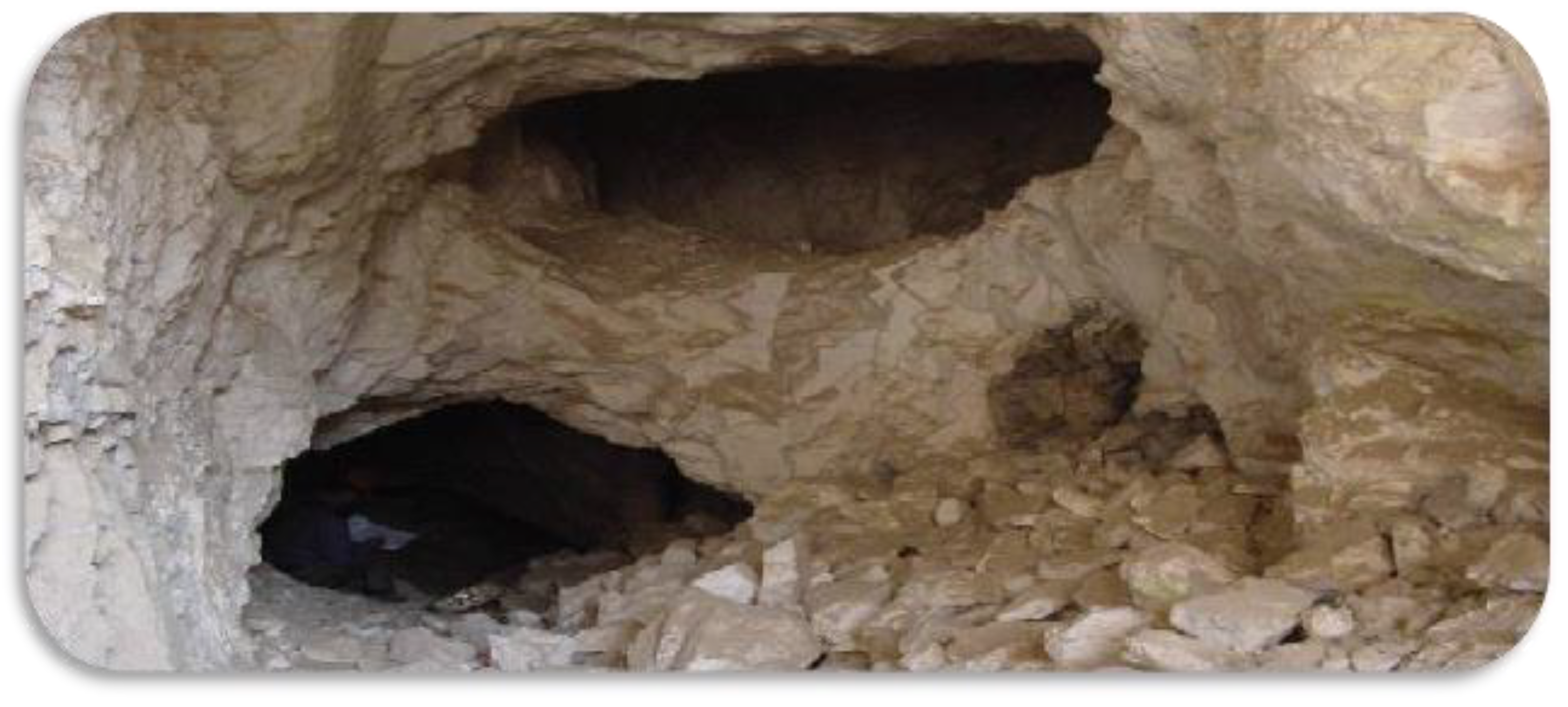
  • After long-term exploitation of wells, the insufficient energy in the formation of fractured carbonate reservoirs leads to a rapid decrease in production, and the water content of crude oil steadily increases. Hydraulic expansion of the fractured carbonate rock may connect fractures and pores that were not affected by the original production, allowing the internal raw oil to enter the production fractures and replenish energy.
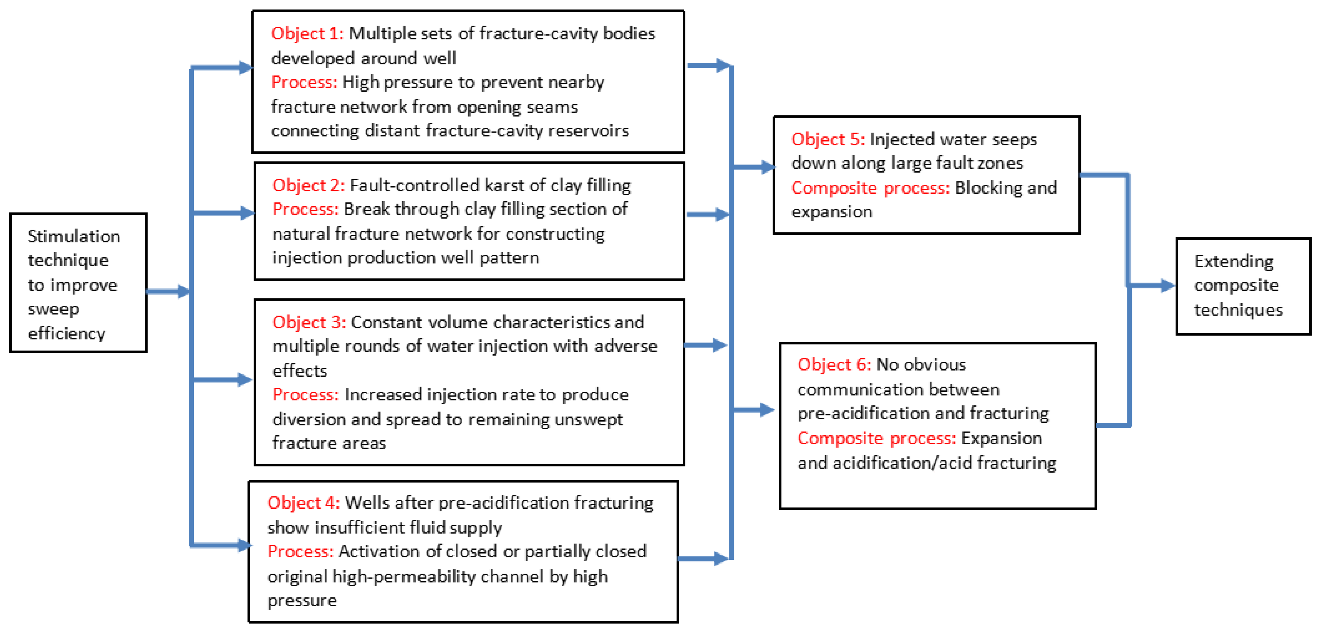
  • For wells with multiple sets of well-developed fractures and cavities in the surrounding area, we apply high pressure to prevent nearby fracture networks from opening and connecting to distant fracture and cavity reservoirs. When controlling karst with clay-filled faults, we increase the injection rate to generate diversion and spread to the remaining non-eroded fracture areas. For wells with insufficient fluid supply after pre-acidification fracturing, we activate sealed or partially sealed original high-permeability channels by applying high pressure.
  • Considering temporary plugging and acid fracturing, we also propose (1) temporary plugging of the main deep fractures, followed by hydraulic expansion, and (2) composite expansion and acidification/compression processes.
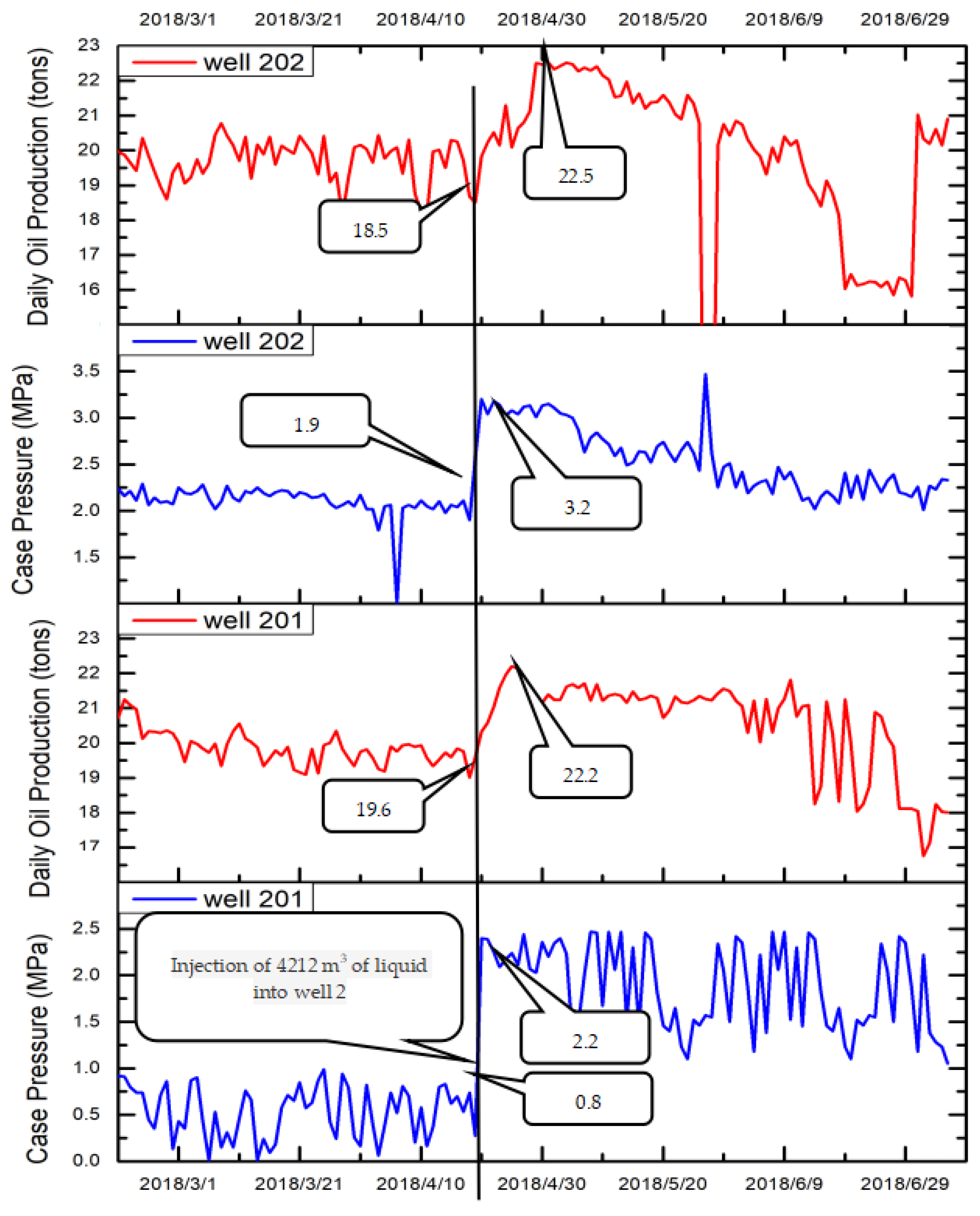
  • Hydraulic expansion allows us to recover and supplement the formation energy and efficiently increase production. We tested various wells, achieving an effective hydraulic expansion rate of up to 85%. In addition, the productivity of conventional water injection and hydraulic expansion after on-site construction was evaluated for one well, clearly indicating the effectiveness of water injection and the remarkable increase in crude oil production after hydraulic expansion.

Author Contributions

Conceptualization, J.L., methodology, J.L. and W.L.; validation, J.S.; formal analysis, J.L. and J.S.; writing, J.L. All authors have read and agreed to the published version of the manuscript.

Funding

This work was supported by the Scientific Research Project “Research on the micro mechanism and treatment method of aging oil containing polymer residue” of the China University of Petroleum (Beijing) at Karamay under grant number XQZX20210005.

Institutional Review Board Statement

Not applicable.

Informed Consent Statement

Not applicable.

Data Availability Statement

The original contributions presented in the study are included in the article, further inquiries can be directed to the corresponding author.

Conflicts of Interest

The authors declare no conflicts of interest.

References

  1. Martyushev, D.A.; Davoodi, S.; Kadkhodaie, A.; Riazi, M.; Kazemzadeh, Y.; Ma, T. Multiscale and diverse spatial heterogeneity analysis of void structures in reef carbonate reservoirs. Geoenergy Sci. Eng. 2024, 233, 212569. [Google Scholar] [CrossRef]
  2. Mohammed-Sajed, O.K.; Glover, P.W.; Al-Khatony, F.H.; Collier, R.E. Qualitative and quantitative diagenetic modelling in a tight carbonatereservoir in north-western Iraq. Geoenergy Sci. Eng. 2024, 232, 212450. [Google Scholar] [CrossRef]
  3. Xiao, S.; Ge, Z.; Lu, Y.; Zhou, Z.; Li, Q.; Wang, L. Investigation on coal fragmentation by high-velocity water jet in drilling: Size distributions and fractal characteristics. Appl. Sci. 2018, 8, 1988. [Google Scholar] [CrossRef]
  4. Zhao, H.; Liu, Z.; Tang, X.; Li, X.; Geng, Y.; Zhang, J. Fracturing technology of searching for vugs along fractures in fractured-vuggy carbonate reservoirs. Petrol. Drilling Prod. Technol. 2021, 43, 89–96. [Google Scholar]
  5. Lu, Z.; Xu, S.; Aini, M.; Wang, C.; Gao, L.; Yang, Z.; Yan, C.; Huo, J. Analysis of reservoir characteristics and their effect on productivity of overseas carbonate reservoirs. Spec. Oil Gas Reserv. 2021, 28, 47–53. [Google Scholar]
  6. Ding, X.; Liu, X.; Qi, Z.; Zhang, W.; Liu, S. Reservoir space characterization of vuggy carbonate reservoirs with multiple scales: A case study of Ma 5–7 interval, Middle Ordovician Majiagou Fornation, Daniudi area, Ordos Basin. Petrol. Geol. Exp. 2021, 43, 689–696. [Google Scholar]
  7. Li, Y.; Zhao, L.; Wang, S.; Sun, L.; Zhang, W.; Yang, Y.; Hu, D.; Chen, Y. Using cyclic alternating water injection to enhance oil recovery for carbonate reservoirs developed by linear horizontal well pattern. Petrol. Explor. Dev. 2021, 48, 1139–1151. [Google Scholar] [CrossRef]
  8. Markova, I.; Markov, M. Secondary porosity classification in heterogeneous carbonate reservoirs based on the sonic log data. J. Appl. Geophys. 2023, 218, 105215. [Google Scholar] [CrossRef]
  9. Chen, L.; Jia, C.; Zhang, R.; Yue, P.; Jiang, X.; Wang, J.; Su, Z.; Xiao, Y.; Lv, Y. High-pressure capacity expansion and water injection mechanism andindicator curve model for fractured-vuggy carbonate reservoirs. Petroleum 2024, in press. [Google Scholar] [CrossRef]
  10. Li, X.; Lei, T.; Yang, Z.; Zhang, X.; Su, Z. Acid fracturing process progress and prospect. Oil Gas Well Test 2014, 23, 43–47. [Google Scholar]
  11. He, J.; Li, X. Overview of hydraulic expansion technology. In Proceedings of the 2019 International Conference on Oil and Gas Field Exploration and Development; Springer: Berlin/Heidelberg, Germany, 2019. [Google Scholar]
  12. Azad, M.; Ghaedi, M.; Farasat, A.; Parvizi, H.; Aghaei, H. Case study of hydraulic fracturing in an offshore carbonate oil reservoir. Petrol. Res. 2022, 7, 419–429. [Google Scholar] [CrossRef]
  13. Saberhosseini, S.E.; Ahangari, K.; Mohammadrezaei, H. Optimization of the horizontal-well multiple hydraulic fracturing operation in a low-permeability carbonate reservoir using fully coupled XFEM model. Int. J. Rock Mech. Min. Sci. 2019, 114, 33–45. [Google Scholar] [CrossRef]
  14. Wang, J.; Zhou, Y. Study on remaining oil distribution of fractured vuggy carbonate reservoir in Tahe 4 area. Petrochem. Technol. 2019, 26, 302–303. [Google Scholar]
  15. Rashid, F.; Hussein, D.; Lorinczi, P.; Glover, P.W. The effect of fracturing on permeability in carbonate reservoir rocks. Mar. Petrol. Geol. 2023, 152, 106240. [Google Scholar] [CrossRef]
  16. Qiu, Z.; Xu, J.; Yang, P.; Zhao, X.; Mou, T.; Zhong, H.; Huang, W. Effect of amphiphilic polymer/nano-silica composite on shale stability for water-based muds. Appl. Sci. 2018, 8, 1839. [Google Scholar] [CrossRef]
  17. Hu, W.G. Development technology and research direction of fractured-vuggy carbonate reservoirs in Tahe Oilfield. Reserv. Eval. Dev. 2020, 10, 1–10. [Google Scholar]
  18. Al-Shargabi, M.; Davoodi, S.; Wood, D.A.; Ali, M.; Rukavishnikov, V.S.; Minaev, K.M. A critical review of self-diverting acid treatments applied to carbonate oil and gas reservoirs. Petrol. Sci. 2023, 20, 922–950. [Google Scholar] [CrossRef]
  19. Rong, J.; Tan, M. Effectiveness analysis of Ordovician carbonate reservoirs in zones 6 and 7 of Tahe Oilfield. In Proceedings of the 2019 Academic Annual Meeting of Oil and Gas Geophysics, Nanjing, China, 28–29 November 2019. [Google Scholar]
  20. Chen, Y. Screening and Research on a Series of Plugging Agents for Carbonate Reservoirs in Tahe Oilfield. Ph.D. Thesis, Xi’an University of Petroleum, Xi’an, China, 2019. [Google Scholar]
Figure 1. Section of a fracture-cavity carbonate reservoir.
Applsci 14 05851 g001
Figure 2. Diagram of production-increasing techniques.
Applsci 14 05851 g002
Figure 3. Construction curve of expansion well 1 under high-pressure hydraulic expansion.
Applsci 14 05851 g003
Figure 4. Production and pressure before and after hydraulic expansion of expansion well 2 and adjacent wells.
Applsci 14 05851 g004
Figure 5. Construction curve of expansion well 3 under hydraulic expansion.
Applsci 14 05851 g005
Figure 6. Production and water content before and after capacity expansion of expansion well 3.
Applsci 14 05851 g006
Figure 7. Production and water content during acidification and hydraulic expansion of expansion well 4.
Applsci 14 05851 g007
Figure 8. Pressure during first round of water injection in expansion well 5.
Applsci 14 05851 g008
Table 1. Construction results of the composite blocking and expansion process.
ProcessWater Injection Displacement
(L/min)
Injection
Type
Injected Water (m3)Particle Displacement
(L/min)
Injection ApproachInjection (m3)Elastic Particles (t)Description
Seal deep cracks in lower part300Positive200300–500Inverted2505 (1–2 mm elastic particles)Medium density ρ = 1.19 rubber particles injected and concentration gradually increasing from small to large
300Positive100300–500Inverted1505 (1–2 mm elastic particles)
Plane advantage temporarily blocks steering300–500Positive100300–500Inverted100 Iso-density ρ = 1.14 rubber particles injected and concentration gradually increasing from small to large
300Positive200300–500Inverted2505 (2–3 mm elastic particles)
300Positive100300–500Inverted1503 (2–3 mm elastic particles)
300–500Positive100300–500Inverted100
Expansion≥900Positive500Pressure drop test and pressure measurements every half-hour for 48 hUse thousand-type pump to increase displacement and achieve high-pressure injection. Objective: achieve expansion of reservoir around well
(Q = 60 m3/h)
≥900Positive1000
≥1500Positive500
Key requirements: (1) Control pressure does not exceed 30 MPa. If the pressure increases, particle injection stops. For large-displacement replacement of salt water, if the pressure remains below 30 MPa, 20 m3 of frozen glue is deployed, and anti-injection is performed. (2) Expansion depends on the actual situation for on-site adjustment. The set pressure should not exceed 55 MPa, and the oil pressure should not exceed 60 MPa. If the construction displacement is large, pipe the network and reverse transport to ensure adequate water supply while increasing the stock of medium-density particles to 10 t for process adjustment in advance and preparation. Do not operate the pump during smooth starting and stopping of equipment, maintenance, or other activities.
Table 2. Construction results of expansion well 6 using the composite expansion and acidification process.
No.Water Injection
Displacement (L/min)
Injection TypeInjected Water (m3)Pump Pressure (MPa)Sleeve (MPa)Description
1200–300–400Positive 30<50<15Monitor amount of injected water
2800–1000Positive 4000<50<15If positive injection pressure exceeds 3–5 MPa, casing begins to achieve balanced pressure and is gradually repressurized to 5–10–15 MPa
3Pressure dropPositive Immediately after water injection, the pipeline is removed, and the pressure drop is measured while the well site is quickly evacuated
4AcidificationPositive Based on acidification design, the fracking team performs this step
Key requirements: (1) If the sealer release is sealed, the pressure is controlled at 24 MPa, and water filling proceeds or the construction is stopped depending on the situation to determine the next step. (2) If the initial pressure is very high (displacement below 30 m3/h and pressure above 30 MPa) and acidic conditions occur, small-scale acidification is considered after water injection or construction is stopped, which should be decided through discussions. (3) According to the situation of on-site adjustment, the whole process pressure should not exceed 30 MPa, and oil pressure should not exceed 50 MPa. If the construction displacement is large, it is necessary to pipe the network and reverse transport to ensure adequate water supply for the processes performed in advance and during preparation. Do not operate the pump during smooth starting and stopping of equipment, maintenance, or other activities.
Table 3. Production obtained from conventional and high-pressure hydraulic expansion.
Water Injection TypeInjected Water
(m3)
Water Pressure
(MPa)
Cycle Fluid Production
(t)
Cycle Oil Production
(t)
Cycle Water Content
(%)
Production Pressure Drop
(MPa)
Fluid Produced per Unit of Pressure Drop
(m3/MPa)
Round three of regular water injection388715586332214529201
First round of high-pressure hydraulic expansion9361232084917563266
Second round of high-pressure hydraulic expansion20,4041914,42913,804426547
Disclaimer/Publisher’s Note: The statements, opinions and data contained in all publications are solely those of the individual author(s) and contributor(s) and not of MDPI and/or the editor(s). MDPI and/or the editor(s) disclaim responsibility for any injury to people or property resulting from any ideas, methods, instructions or products referred to in the content.

