
The Influence of Powering a Compression Ignition Engine with HVO Fuel on the Specific Emissions of Selected Toxic Exhaust Components

Abstract
:1. Introduction
2. Materials and Methods
2.1. Fuel
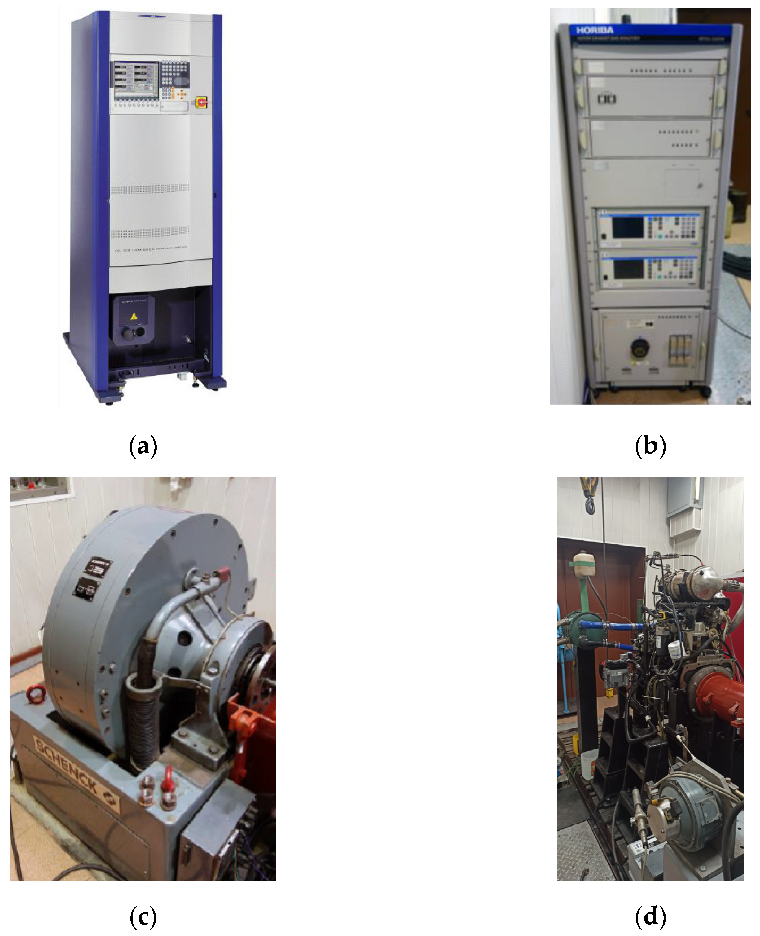
2.2. Test Stand
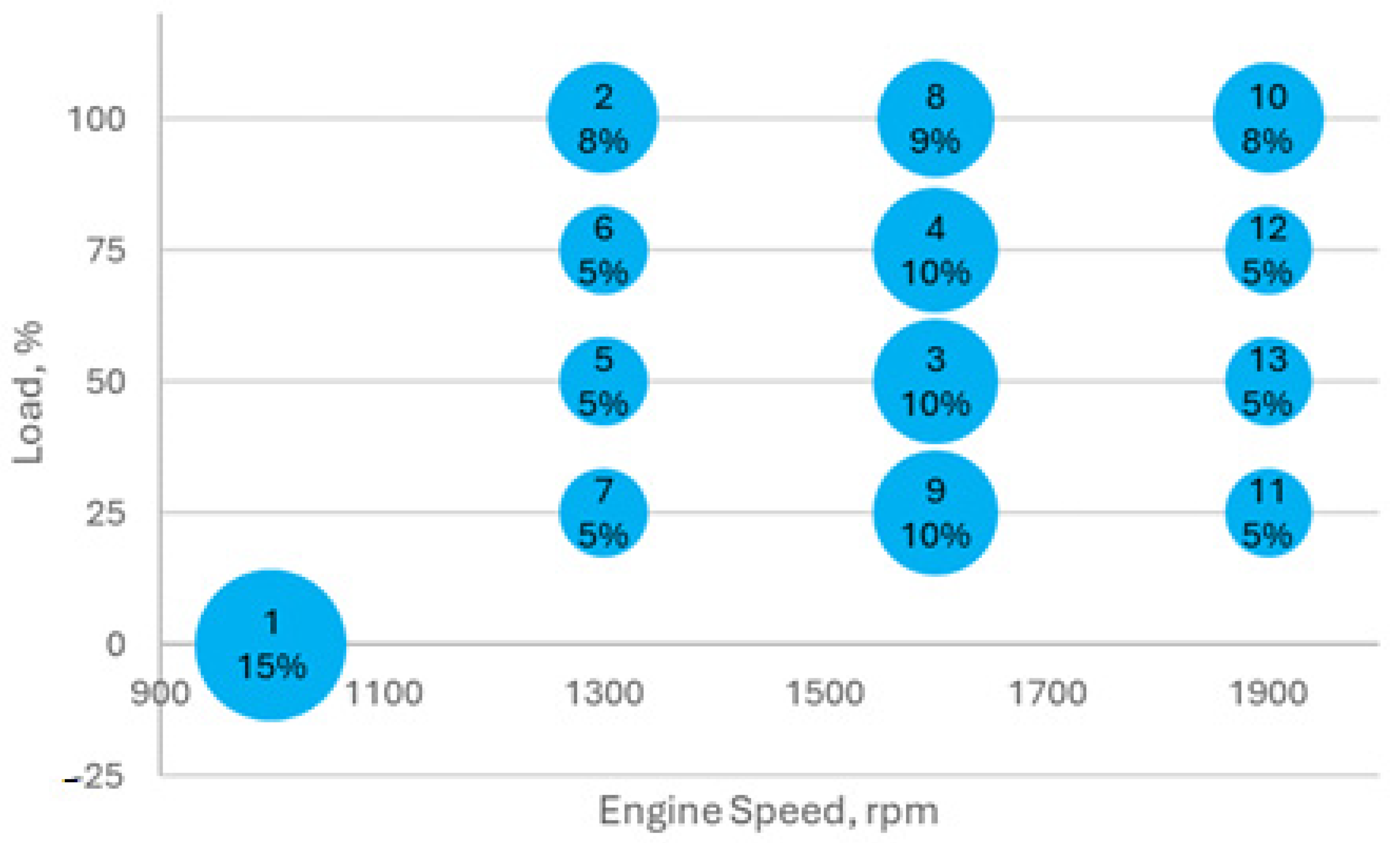
2.3. ESC Test
3. Results
4. Discussion
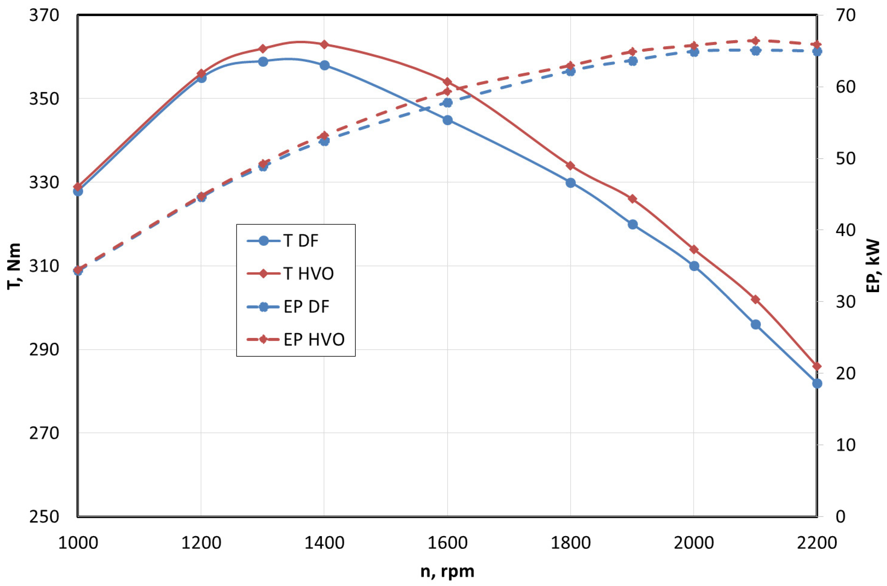
- Speed characteristics at a full load:
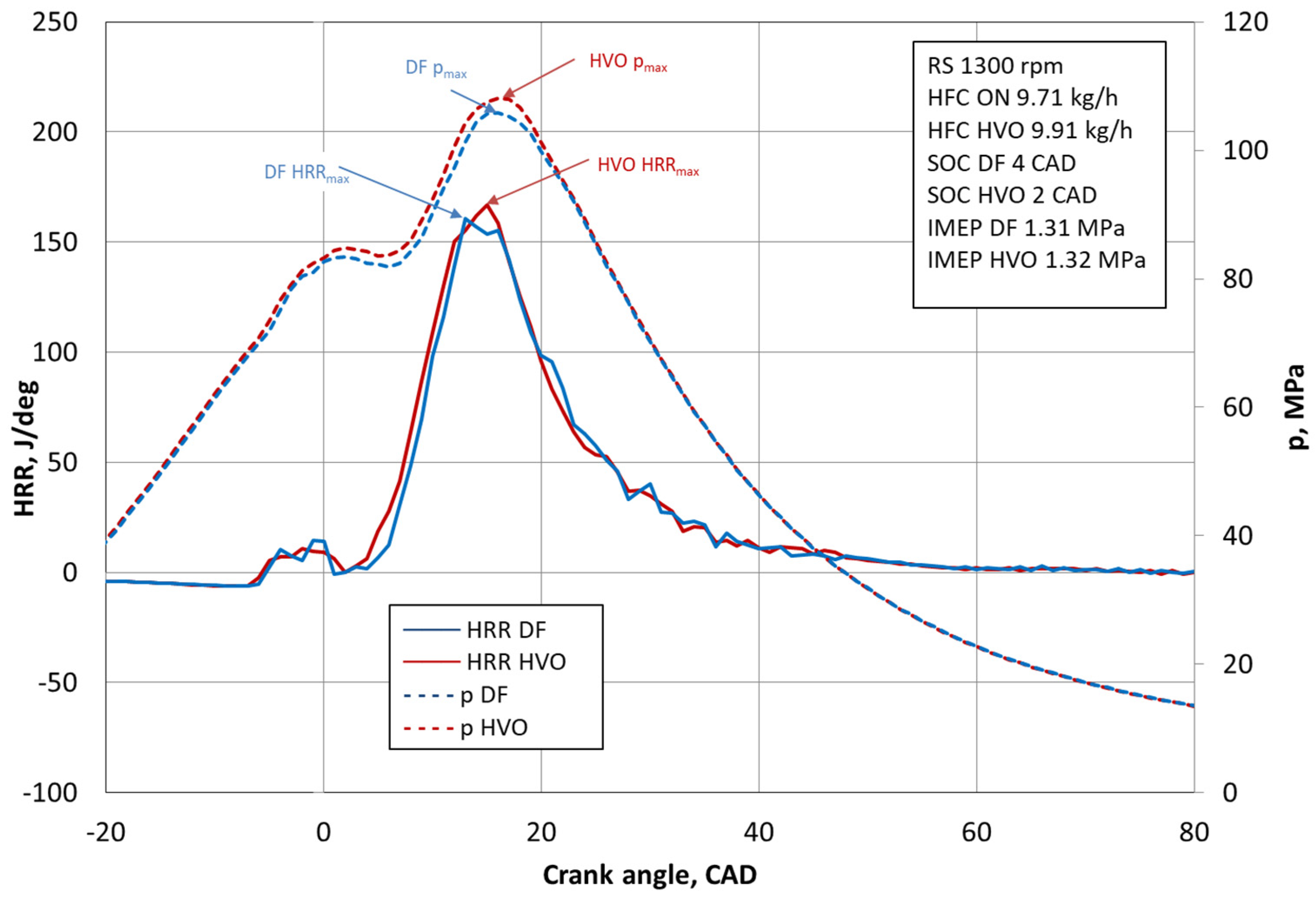
- The analysis of the results of the instantaneous pressure and temperature in the combustion chamber as a function of the crankshaft rotation angle shows the following for HVO fuel:
- -
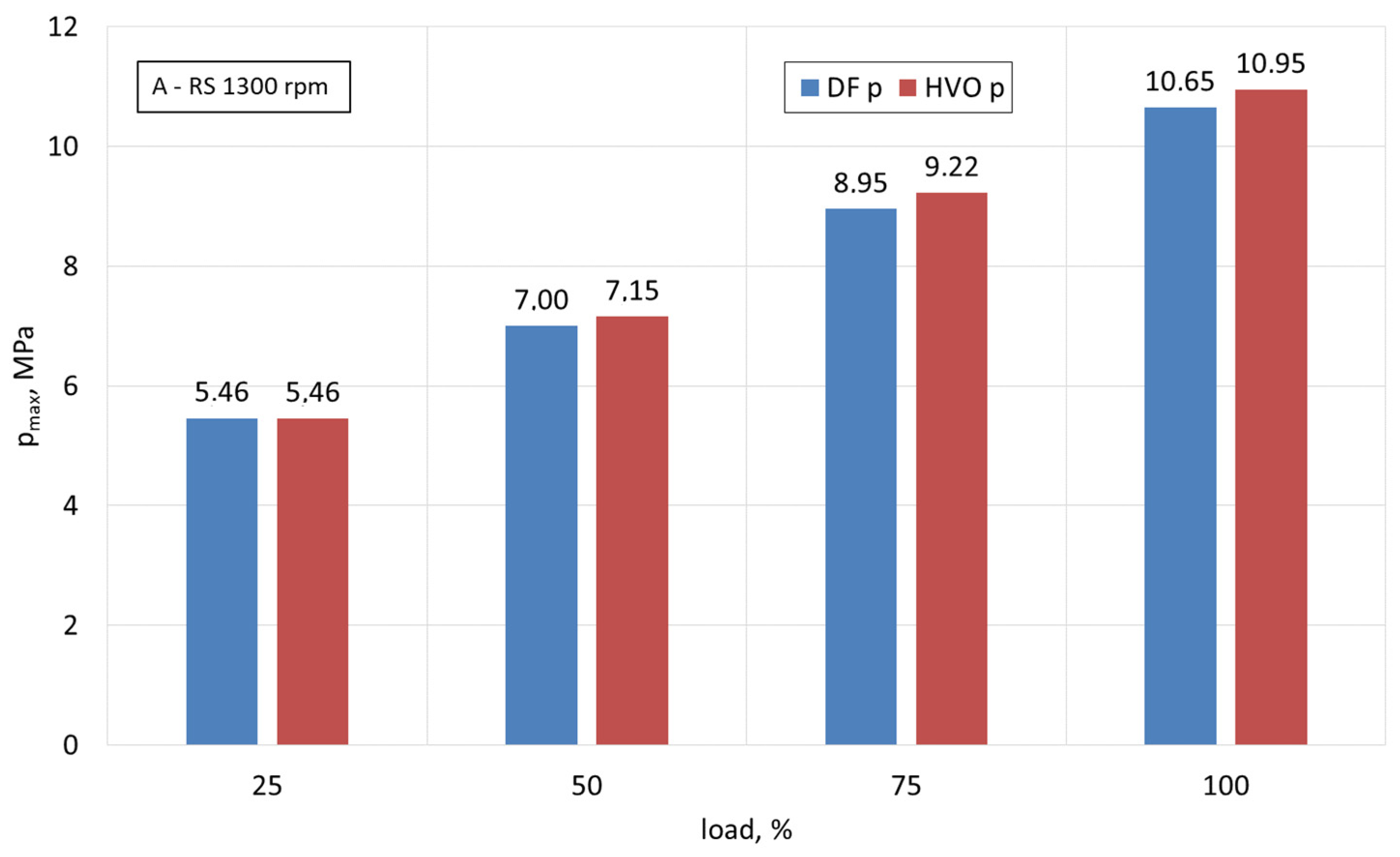
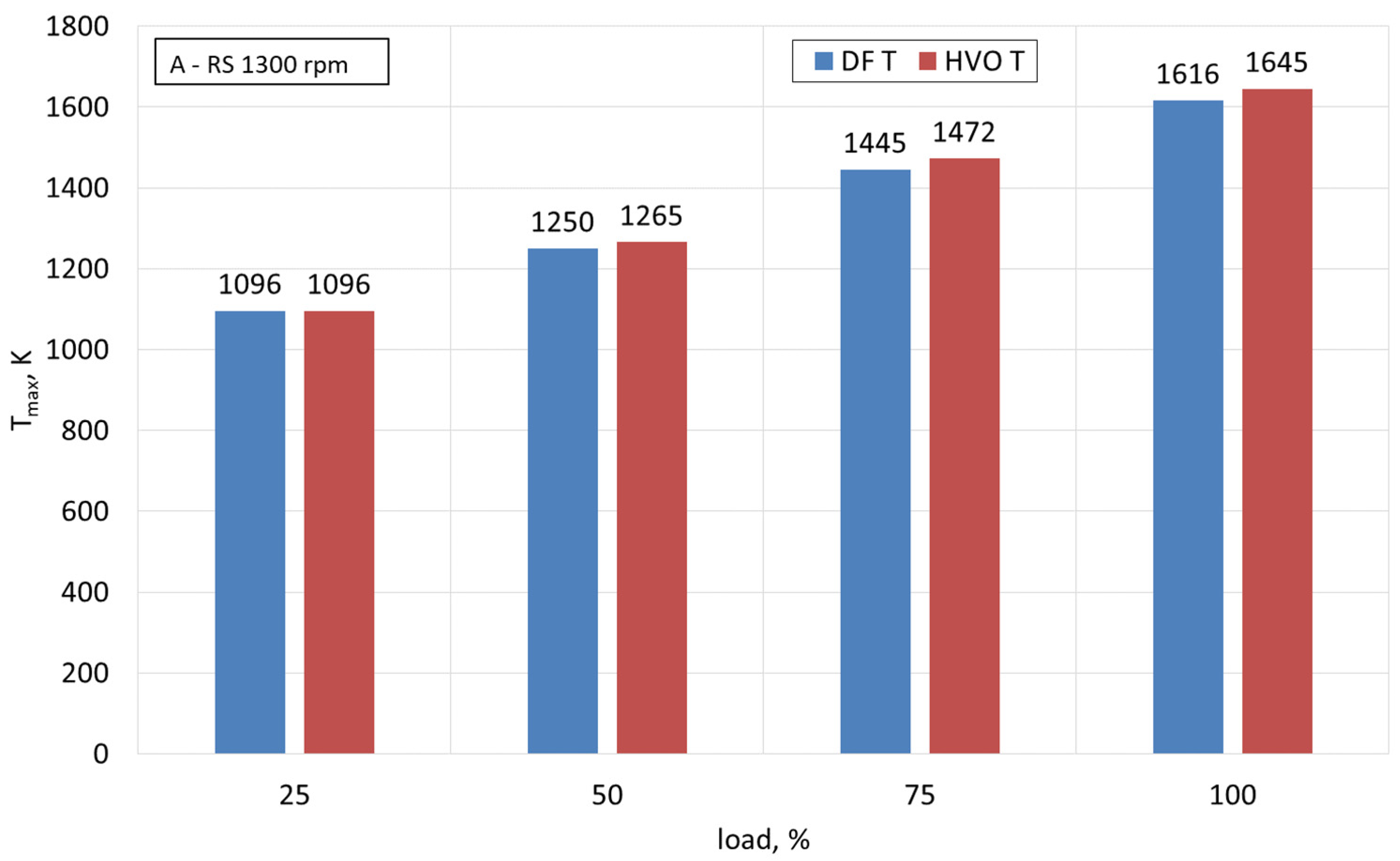
- Earlier start of the combustion process by 2 degrees CAD (Figure 6) and, consequently, an increase in the maximum temperature in the combustion chamber by approximately 30 K and in the maximum pressure by 0.3 MPa for the maximum load and rotational speed of 1300 rpm (Figure 7 and Figure 8). At lower loads, the differences are smaller for both fuels, and at an engine load of 25%, no difference was observed.
- -
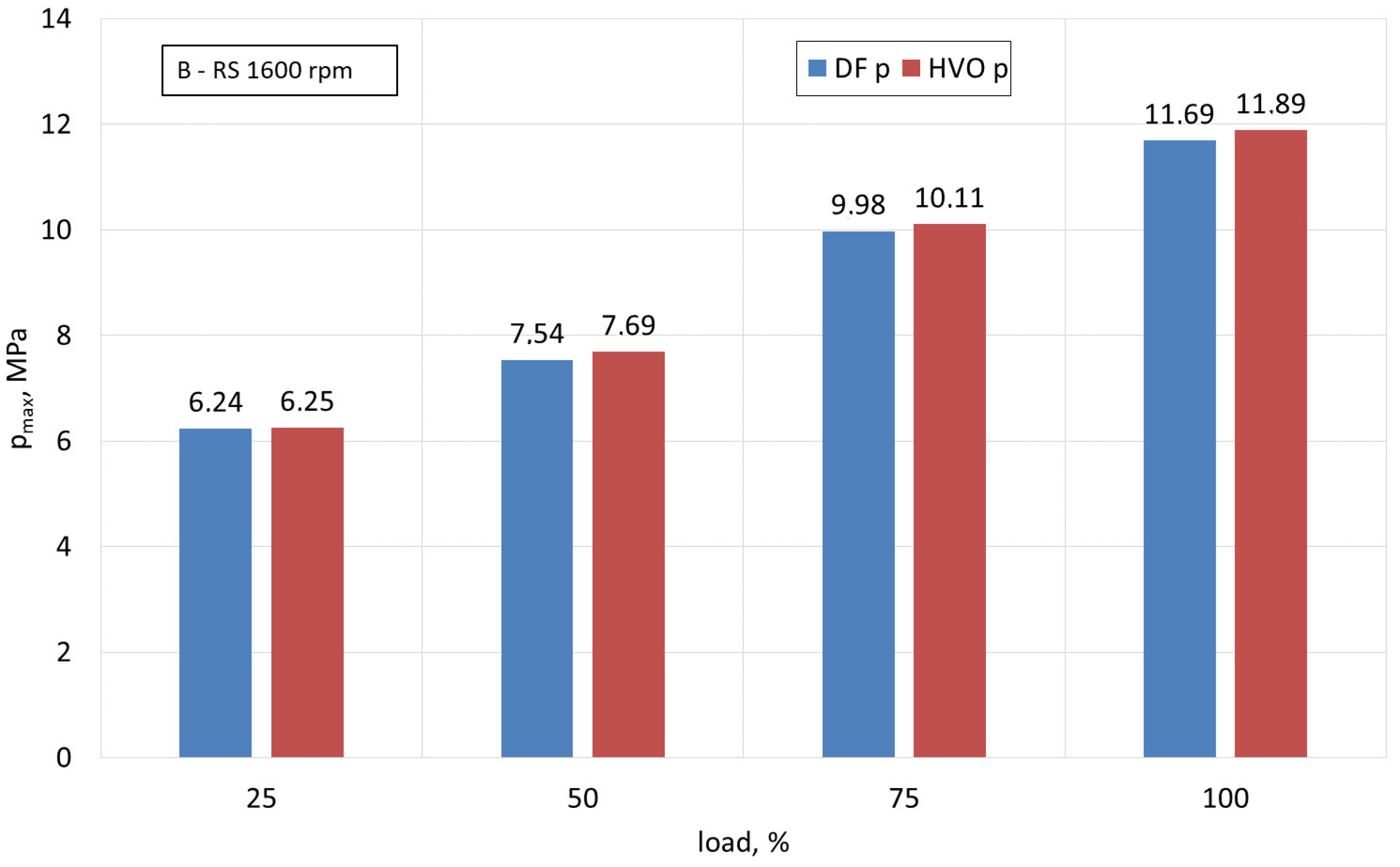
- Earlier start of the combustion process, resulting in an increase in the maximum temperature in the combustion chamber by approximately 20 K and in the maximum pressure by 0.2 MPa for the maximum load and rotational speed of 1600 rpm (Figure 9 and Figure 10). At lower loads, the differences are smaller for both fuels, and at an engine load of 25%, no difference was observed.
- -
- Earlier start of the combustion process, resulting in an increase in the maximum temperature in the combustion chamber by approximately 17 K and in the maximum pressure by 0.16 MPa for the maximum load and rotational speed of 1900 rpm (Figure 11 and Figure 12). At lower loads, the differences are smaller for both fuels, and at an engine load of 25%, no difference was observed.
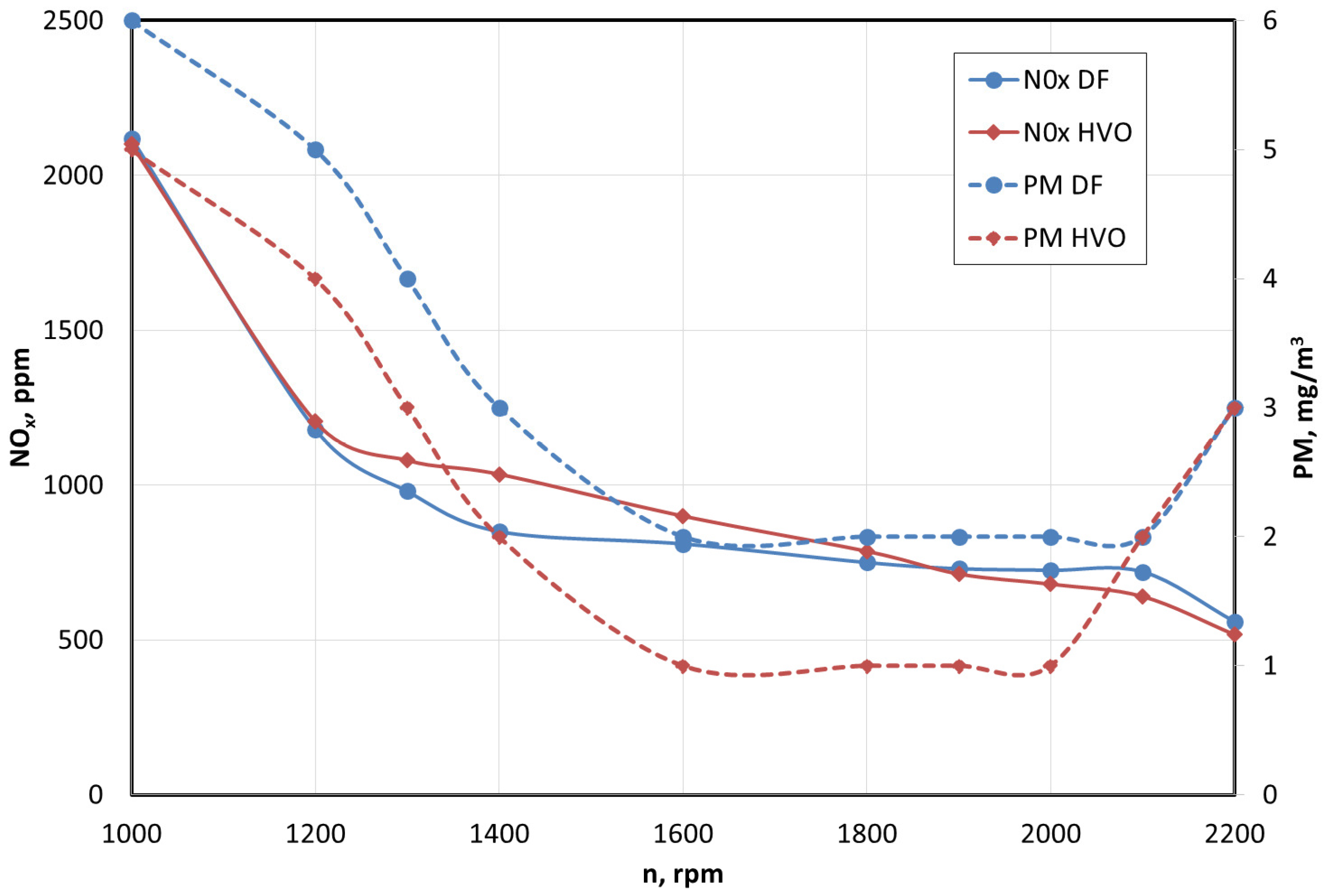
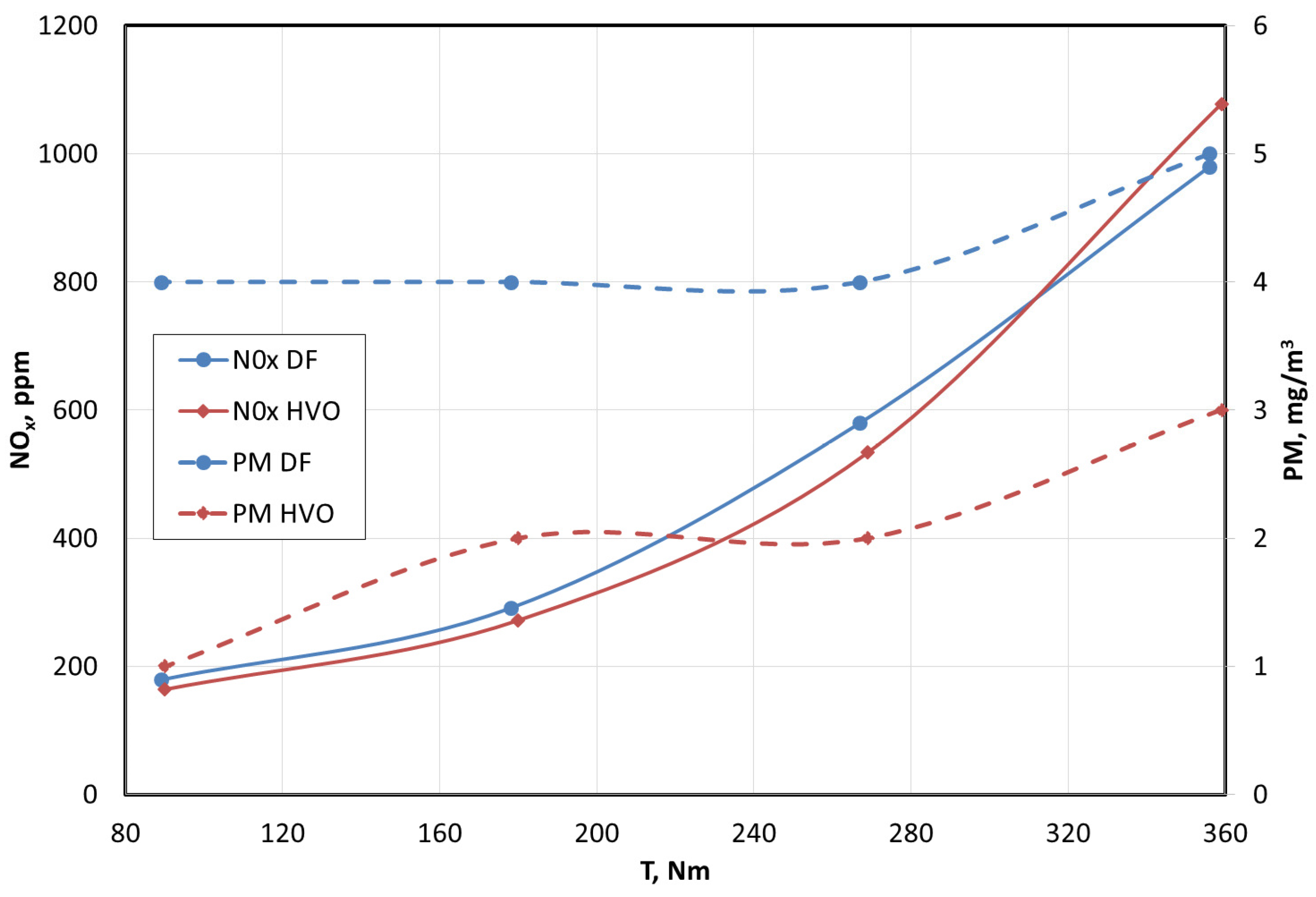
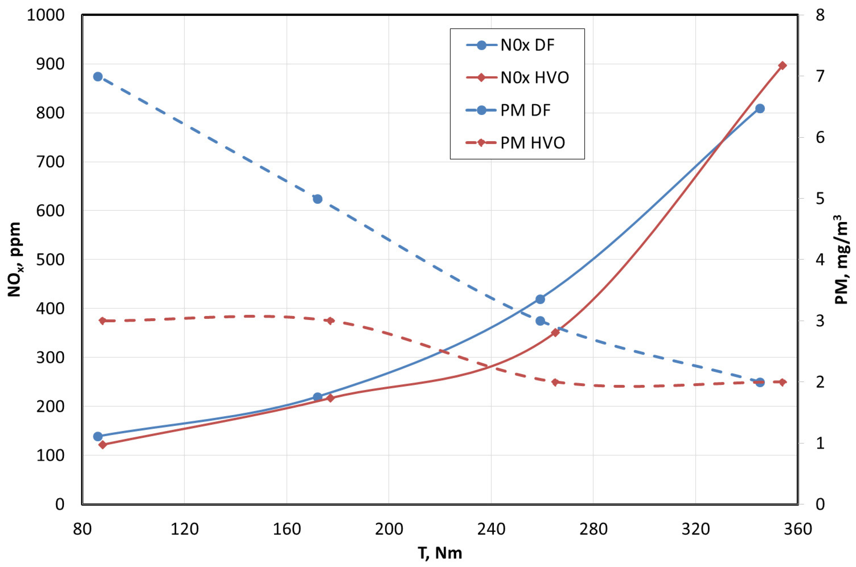
- Emissions of harmful substances:The speed characteristics (Figure 13) show that NOx concentrations are higher for HVO fuel (by a maximum of 18%), and particulate matter is 50% lower than for DF.The load characteristics for 1300 rpm (Figure 14) show that NOx concentrations are higher for HVO fuel, but only at the maximum load. As the load decreases, the trend reverses and HVO fuel shows a maximum of 7% lower NOx concentration than DF. In the case of HVO fuel, PM emissions in the entire range of tested load characteristics show lower emissions by up to 75% (at a low engine load).On the load characteristics for 1600 rpm (Figure 15), NOx concentrations are higher for HVO fuel, but only at the maximum load. As the load decreases, the trend reverses and HVO shows a maximum of 17% lower NOx concentration than DF. In the case of HVO fuel, PM emissions in the entire tested load range are lower by up to 58% (at a low engine load).On the load curve at 1900 rpm (Figure 16), NOx concentrations are about 17% lower for HVO, but only at the maximum load. As the load decreases, both fuels show similar emissions (maximum 4% difference)For HVO, particulate matter in the entire tested range is characterized by lower emissions by up to 56% (at a low engine load).
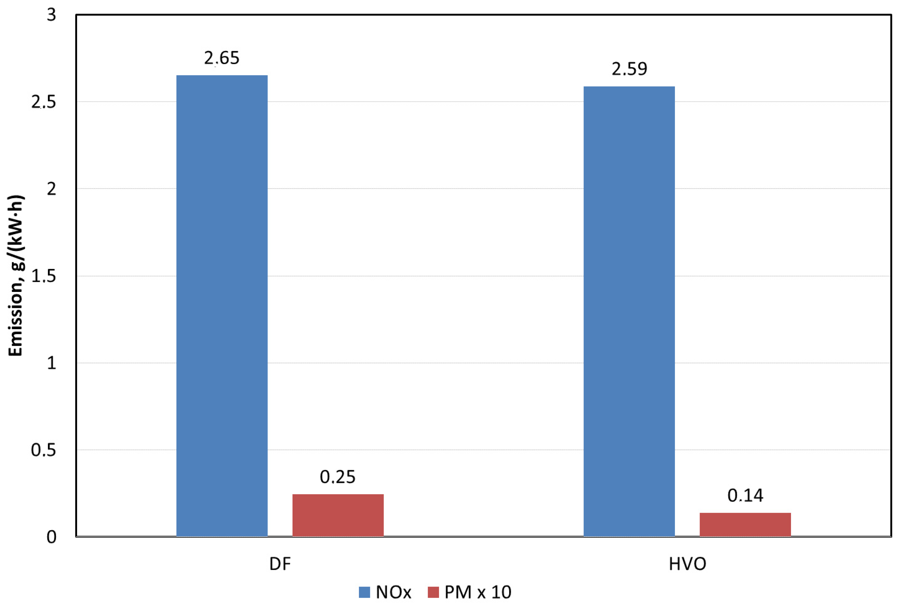
- The specific NOx emissions determined in the ESC test for the Perkins 854E-E34TA engine are 2.3% lower for HVO. Specific PM emissions are 43% lower for HVO compared to DF.
5. Conclusions
Author Contributions
Funding
Institutional Review Board Statement
Informed Consent Statement
Conflicts of Interest
Abbreviations
| ACEA | European Automobile Manufacturers’ Association |
| CAD | crank angle degree |
| DF | diesel fuel |
| EP | effective power |
| ESC | European Stationary Cycle |
| FAME | fatty acid methyl esters |
| HFC | hourly fuel consumption |
| HRF | heat release fraction |
| HRR | heat release rate |
| HVO | hydrogenated vegetable oil |
| NOx | nitrogen oxides |
| OICA | International Organization of Automobile Manufacturers |
| p | pressure in the combustion chamber |
| PM | particulate matter |
| RS, n | engine crankshaft rotation speed |
| SFC | specific fuel consumption |
| SOC | start of combustion |
| T | engine crankshaft torque |
| VF | volume flow |
References
- Rimkus, A.; Stravinskas, S.; Matijošius, J. Comparative Study on the Energetic and Ecologic Parameters of Dual Fuels (Diesel–NG and HVO–Biogas) and Conventional Diesel Fuel in a CI Engine. Appl. Sci. 2020, 10, 359. [Google Scholar] [CrossRef]
- Beatrice, C.; Denbratt, I.; Di Blasio, G.; Di Luca, G.; Ianniello, R.; Saccullo, M. Experimental Assessment on Exploiting Low Carbon Ethanol Fuel in a Light-Duty Dual-Fuel Compression Ignition Engine. Appl. Sci. 2020, 10, 7182. [Google Scholar] [CrossRef]
- Smigins, R.; Sondors, K.; Pirs, V.; Dukulis, I.; Birzietis, G. Studies of Engine Performance and Emissions at Full-Load Mode Using HVO, Diesel Fuel, and HVO5. Energies 2023, 16, 4785. [Google Scholar] [CrossRef]
- Stępień, Z. Synthetic Automotive Fuels. Combust. Engines 2023, 192, 78–90. [Google Scholar] [CrossRef]
- d’Ambrosio, S.; Mancarella, A.; Manelli, A. Utilization of Hydrotreated Vegetable Oil (HVO) in a Euro 6 Dual-Loop EGR Diesel Engine: Behavior as a Drop-In Fuel and Potentialities along Calibration Parameter Sweeps. Energies 2022, 15, 7202. [Google Scholar] [CrossRef]
- Pardhi, S.; El Baghdadi, M.; Hulsebos, O.; Hegazy, O. Optimal Powertrain Sizing of Series Hybrid Coach Running on Diesel and HVO for Lifetime Carbon Footprint and Total Cost Minimisation. Energies 2022, 15, 6974. [Google Scholar] [CrossRef]
- Sikora, M.; Orliński, P.; Matej, J. Hydro-Treated Vegetable Oil as a Potential Biofuel for Self-Ignition Engines. Transp. Samoch. 2022, 1, 14–20. [Google Scholar] [CrossRef]
- Chojnowski, J.; Nogas, P. The Potential of Hydrotreated Vegetable Oil (HVO) as a High-Reactive Biofuel in Dual-Fuel Power Systems. Biul. Wojsk. Akad. Tech. 2021, 70, 65–76. [Google Scholar] [CrossRef]
- Hunicz, J.; Krzaczek, P.; Gęca, M.; Rybak, A.; Mikulski, M. Comparative Study of Combustion and Emissions of Diesel Engine Fuelled with FAME and HVO. Combust. Engines 2021, 184, 72–78. [Google Scholar] [CrossRef]
- Kurczyński, D.; Wcisło, G.; Łagowski, P. Experimental Study of Fuel Consumption and Exhaust Gas Composition of a Diesel Engine Powered by Biodiesel from Waste of Animal Origin. Energies 2021, 14, 3472. [Google Scholar] [CrossRef]
- Preuß, J.; Munch, K.; Denbratt, I. Performance and Emissions of Renewable Blends with OME3-5 and HVO in Heavy Duty and Light Duty Compression Ignition Engines. Fuel 2021, 303, 121275. [Google Scholar] [CrossRef]
- Serrano, L.; Santana, B.; Pires, N.; Correia, C. Performance, Emissions, and Efficiency of Biodiesel versus Hydrotreated Vegetable Oils (HVO), Considering Different Driving Cycles Sensitivity Analysis (NEDC and WLTP). Fuels 2021, 2, 448–470. [Google Scholar] [CrossRef]
- Sikora, M.; Orliński, P.; Bednarski, M. Research of Nitrogen Oxides Concentrations in Exhaust Gas of Compression Ignition Engine Fuelled with Alternative Fuel. Adv. Sci. Technol. Res. J. 2021, 15, 75–83. [Google Scholar] [CrossRef] [PubMed]
- Bjørgen, K.O.P.; Emberson, D.R.; Løvås, T. Combustion and Soot Characteristics of Hydrotreated Vegetable Oil Compression-Ignited Spray Flames. Fuel 2020, 266, 116942. [Google Scholar] [CrossRef]
- Grzelak, P.; Żółtowski, A. Environmental Assessment of the Exploitation of Diesel Engines Powered by Biofuels. Combust. Engines 2020, 180, 31–35. [Google Scholar] [CrossRef]
- Dimitriadis, A.; Seljak, T.; Baškovič, U.Ž.; Dimaratos, A.; Bezergianni, S.; Samaras, Z.; Katrašnik, T. Improving PM-NOx trade-off with paraffinic fuels: A study towards diesel engine optimization with HVO. Fuel 2020, 265, 116921. [Google Scholar] [CrossRef]
- Suarez-Bertoa, R.; Kousoulidou, M.; Clairotte, M.; Giechaskiel, B.; Nuottimäki, J.; Sarjovaara, T.; Lonza, L. Impact of HVO Blends on Modern Diesel Passenger Cars Emissions during Real World Operation. Fuel 2019, 235, 1427–1435. [Google Scholar] [CrossRef]
- Zeman, P.; Hönig, V.; Kotek, M.; Táborský, J.; Obergruber, M.; Mařík, J.; Hartová, V.; Pechout, M. Hydrotreated Vegetable Oil as a Fuel from Waste Materials. Catalysts 2019, 9, 337. [Google Scholar] [CrossRef]
- Bohl, T.; Smallbone, A.; Tian, G.; Roskilly, A.P. Particulate Number and NOx Trade-off Comparisons between HVO and Mineral Diesel in HD Applications. Fuel 2018, 215, 90–101. [Google Scholar] [CrossRef]
- Dimitriadis, A.; Natsios, I.; Dimaratos, A.; Katsaounis, D.; Samaras, Z.; Bezergianni, S.; Lehto, K. Evaluation of a Hydrotreated Vegetable Oil (HVO) and Effects on Emissions of a Passenger Car Diesel Engine. Front. Mech. Eng. 2018, 4, 7. [Google Scholar] [CrossRef]
- Kruczyński, S.; Gis, W.; Orliński, P.; Sikora, M. Influence of the Use of Ethanol Fuel on Selected Parameters of the Gasoline Engine. IOP Conf. Ser. Mater. Sci. Eng. 2018, 421, 042041. [Google Scholar] [CrossRef]
- Pinto, G.M.; da Costa, R.B.R.; de Souza, T.A.Z.; Rosa, A.J.A.C.; Raats, O.O.; Roque, L.F.A.; Frez, G.V.; Coronado, C.J.R. Experimental Investigation of Performance and Emissions of a CI Engine Operating with HVO and Farnesane in Dual-Fuel Mode with Natural Gas and Biogas. Energy 2023, 277, 127648. [Google Scholar] [CrossRef]
- Pinto, G.M.; de Souza, T.A.Z.; da Costa, R.B.R.; Roque, L.F.A.; Frez, G.V.; Coronado, C.J.R. Combustion, Performance and Emission Analyses of a CI Engine Operating with Renewable Diesel Fuels (HVO/FARNESANE) under Dual-Fuel Mode through Hydrogen Port Injection. Int. J. Hydrogen Energy 2023, 48, 19713–19732. [Google Scholar] [CrossRef]
- Roque, L.F.A.; da Costa, R.B.R.; de Souza, T.A.Z.; Coronado, C.J.R.; Pinto, G.M.; Cintra, A.J.A.; Raats, O.O.; Oliveira, B.M.; Frez, G.V.; Alves, L.F.R. Experimental Analysis and Life Cycle Assessment of Green Diesel (HVO) in Dual-Fuel Operation with Bioethanol. J. Clean. Prod. 2023, 389, 135989. [Google Scholar] [CrossRef]
- da Costa, R.B.R.; Roque, L.F.A.; de Souza, T.A.Z.; Coronado, C.J.R.; Pinto, G.M.; Cintra, A.J.A.; Raats, O.O.; Oliveira, B.M.; Frez, G.V.; da Silva, M.H. Experimental Assessment of Renewable Diesel Fuels (HVO/Farnesane) and Bioethanol on Dual-Fuel Mode. Energy Convers. Manag. 2022, 258, 115554. [Google Scholar] [CrossRef]
- Di Blasio, G.; Ianniello, R.; Beatrice, C. Hydrotreated Vegetable Oil as Enabler for High-Efficient and Ultra-Low Emission Vehicles in the View of 2030 Targets. Fuel 2022, 310, 122206. [Google Scholar] [CrossRef]
- McCaffery, C.; Zhu, H.; Sabbir Ahmed, C.M.; Canchola, A.; Chen, J.Y.; Li, C.; Johnson, K.C.; Durbin, T.D.; Lin, Y.H.; Karavalakis, G. Effects of Hydrogenated Vegetable Oil (HVO) and HVO/Biodiesel Blends on the Physicochemical and Toxicological Properties of Emissions from an off-Road Heavy-Duty Diesel Engine. Fuel 2022, 323, 124283. [Google Scholar] [CrossRef]
- Szeto, W.; Leung, D.Y.C. Is Hydrotreated Vegetable Oil a Superior Substitute for Fossil Diesel? A Comprehensive Review on Physicochemical Properties, Engine Performance and Emissions. Fuel 2022, 327, 125065. [Google Scholar] [CrossRef]
- Kumar, N.; Sonthalia, A.; Tomar, M.; Koul, R. An Experimental Investigation on Spray, Performance and Emission of Hydrotreated Waste Cooking Oil Blends in an Agricultural Engine. Int. J. Engine Res. 2021, 22, 2305–2317. [Google Scholar] [CrossRef]
- Parravicini, M.; Barro, C.; Boulouchos, K. Experimental Characterization of GTL, HVO, and OME Based Alternative Fuels for Diesel Engines. Fuel 2021, 292, 120177. [Google Scholar] [CrossRef]
- Lorenzi, G.; Baptista, P.; Venezia, B.; Silva, C.; Santarelli, M. Use of Waste Vegetable Oil for Hydrotreated Vegetable Oil Production with High-Temperature Electrolysis as Hydrogen Source. Fuel 2020, 278, 117991. [Google Scholar] [CrossRef]
- Bortel, I.; Vávra, J.; Takáts, M. Effect of HVO Fuel Mixtures on Emissions and Performance of a Passenger Car Size Diesel Engine. Renew. Energy 2019, 140, 680–691. [Google Scholar] [CrossRef]
- Cheng, Q.; Tuomo, H.; Kaario, O.T.; Martti, L. Spray Dynamics of HVO and EN590 Diesel Fuels. Fuel 2019, 245, 198–211. [Google Scholar] [CrossRef]
- Li, Y.; Xu, H.; Cracknell, R.; Head, R.; Shuai, S. An Experimental Investigation into Combustion Characteristics of HVO Compared with TME and ULSD at Varied Blend Ratios. Fuel 2019, 255, 115757. [Google Scholar] [CrossRef]
- Soam, S.; Hillman, K. Factors Influencing the Environmental Sustainability and Growth of Hydrotreated Vegetable Oil (HVO) in Sweden. Bioresour. Technol. Rep. 2019, 7, 100244. [Google Scholar] [CrossRef]
- Sugiyama, K.; Goto, I.; Kitano, K.; Mogi, K.; Honkanen, M. Effects of hydrotreated vegetable oil (HVO) as renewable diesel fuel on combustion and exhaust emissions in diesel engine. SAE Int. J. Fuels Lubr. 2012, 5, 205–217. [Google Scholar] [CrossRef]
- Sonthalia, A.; Kumar, N. Hydroprocessed Vegetable Oil as a Fuel for Transportation Sector: A Review. J. Energy Inst. 2019, 92, 1–17. [Google Scholar] [CrossRef]
- Ambat, I.; Srivastava, V.; Sillanpää, M. Recent Advancement in Biodiesel Production Methodologies Using Various Feedstock: A Review. Renew. Sustain. Energy Rev. 2018, 90, 356–369. [Google Scholar] [CrossRef]
- Ko, J.; Jin, D.; Jang, W.; Myung, C.L.; Kwon, S.; Park, S. Comparative Investigation of NOx Emission Characteristics from a Euro 6-Compliant Diesel Passenger Car over the NEDC and WLTC at Various Ambient Temperatures. Appl. Energy 2017, 187, 652–662. [Google Scholar] [CrossRef]
- Permpool, N.; Gheewala, S.H. Environmental and Energy Assessment of Alternative Fuels for Diesel in Thailand. J. Clean. Prod. 2017, 142, 1176–1182. [Google Scholar] [CrossRef]
- Operation and Maintenance Manuals | Perkins. Available online: https://www.perkins.com/en_GB/aftermarket/operation-maintenance-manuals.html (accessed on 24 February 2024).
- AVL | PDF | Exhaust Gas | Diesel Engine. Available online: https://www.scribd.com/document/314137703/AVL (accessed on 24 February 2024).
- Chłopek, Z.; Lasocki, J.; Wójcik, P.; Badyda, A.J. Experimental Investigation and Comparison of Energy Consumption of Electric and Conventional Vehicles Due to the Driving Pattern. Int. J. Green Energy 2018, 15, 773–779. [Google Scholar] [CrossRef]
- Samoilenko, D.; Cho, H.M. Improvement of Combustion Efficiency and Emission Characteristics of IC Diesel Engine Operating on ESC Cycle Applying Variable Geometry Turbocharger (VGT) with Vaneless Turbine Volute. Int. J. Automot. Technol. 2013, 14, 521–528. [Google Scholar] [CrossRef]
- Andrych-Zalewska, M.; Chlopek, Z.; Merkisz, J.; Pielecha, J. Investigations of Exhaust Emissions from a Combustion Engine under Simulated Actual Operating Conditions in Real Driving Emissions Test. Energies 2021, 14, 935. [Google Scholar] [CrossRef]
- Algieri, A.; Amelio, M.; Morrone, P. A Comparative Energetic Analysis of Active and Passive Emission Control Systems Adopting Standard Emission Test Cycles. Model. Simul. Eng. 2012, 2012, 786252. [Google Scholar] [CrossRef]
- Chłopek, Z.; Biedrzycki, J.; Lasocki, J.; Wójcik, P.; Samson-Bręk, I. Modelling of Motor Vehicle Operation for the Evaluation of Pollutant Emission and Fuel Consumption. Combust. Engines 2017, 171, 156–163. [Google Scholar] [CrossRef]
- Žvirblis, T.; Hunicz, J.; Matijošius, J.; Rimkus, A.; Kilikevičius, A.; Gęca, M. Improving Diesel Engine Reliability Using an Optimal Prognostic Model to Predict Diesel Engine Emissions and Performance Using Pure Diesel and Hydrogenated Vegetable Oil. Eksploat. I Niezawodn.–Maint. Reliab. 2023, 25, 174358. [Google Scholar] [CrossRef]
- Czerwiński, J.; Zimmerli, Y.; Hussy, A.; Engelmann, D.; Bonsack, P.; Remmele, E.; Huber, G. Testing and Evaluating Real Driving Emissions with PEMS. Combust. Engines 2018, 174, 17–25. [Google Scholar] [CrossRef]
- Bednarski, M.; Orliński, P.; Wojs, M.; Gis, M. Evaluation of the Heat Release Rate during the Combustion Process in the Diesel Engine Chamber Powered with Fuel from Renewable Energy Sources. Bull. Polish Acad. Sci. Tech. Sci. 2020, 68, 1333–1339. [Google Scholar] [CrossRef]
- Bednarski, M.; Orliński, P.; Wojs, M.K.; Sikora, M. Evaluation of Methods for Determining the Combustion Ignition Delay in a Diesel Engine Powered by Liquid Biofuel. J. Energy Inst. 2019, 92, 1107–1114. [Google Scholar] [CrossRef]


| Properties | Unit | Method | HVO | Diesel Fuel |
|---|---|---|---|---|
| Kinematic viscosity | - | 2.646 | 2.969 | |
| Density (at 15 °C) | - | 778 | 830 | |
| Dynamic viscosity | Pa·s | - | ||
| Cetane number | - | ASTM-D613 | 79.7 | 54.6 |
| Pour point | K | ISO3016 | 215 | 234 |
| Flash point | K | ISO2719 | 339 | 344 |
| Cold filter Plugging point | K | EN 116 | 229 | 251 |
| Total aromatic | % v/v | - | 0 | 23.1 |
| Polyaromatic | % v/v | - | 0 | 3.0 |
| Monoaromatic | % v/v | - | 0.50 | 20.1 |
| Flammability | K | - | 334 | 347 |
| Lower heating | - | |||
| Sulfur | % m/m | - | 0.53 | 6.50 |
| Carbon | % m/m | - | 85 | 85.67 |
| Oxygen | % m/m | - | 0 | 0.61 |
| Hydrogen | % m/m | - | 15 | 13.72 |
| Ash content | % m/m | EN ISO 6245 | 0.002 | 0.014 |
| FAME | % v/v | - | 0.05 | 5 |
| Approx. formula | % v/v | - | C13H28 | C13H24O0.06 |
| Mode | Unit | Engine Speed |
|---|---|---|
| Cylinder arrangement | - | in-line |
| Number of cylinders | - | 4 |
| Type of injection | - | direct |
| Compression ratio | - | 17 |
| Cylinder diameter | mm | 99 |
| Piston stroke | mm | 110 |
| Engine displacement | dm3 | 3.4 |
| Engine type | - | compression ignition |
| Nominal power | kW | 86 |
| Nominal power speed | rpm | 2200 |
| Maximum torque | Nm | 450 |
| Speed at maximum torque | rpm | 1400 |
| Species | Range | Analyzer Error |
|---|---|---|
| NOx | Low: 30–5000 | ±1 ppm |
| High: 50–10,000 | ±2 ppm |
| Mode | Weight, % | Engine Speed | Load, % |
|---|---|---|---|
| 1 | 15 | Low idle | 0 |
| 2 | 8 | A | 100 |
| 3 | 10 | B | 50 |
| 4 | 10 | B | 75 |
| 5 | 5 | A | 50 |
| 6 | 5 | A | 75 |
| 7 | 5 | A | 25 |
| 8 | 9 | B | 100 |
| 9 | 10 | B | 25 |
| 10 | 8 | C | 100 |
| 11 | 5 | C | 25 |
| 12 | 5 | C | 75 |
| 13 | 5 | C | 50 |
Disclaimer/Publisher’s Note: The statements, opinions and data contained in all publications are solely those of the individual author(s) and contributor(s) and not of MDPI and/or the editor(s). MDPI and/or the editor(s) disclaim responsibility for any injury to people or property resulting from any ideas, methods, instructions or products referred to in the content. |
© 2024 by the authors. Licensee MDPI, Basel, Switzerland. This article is an open access article distributed under the terms and conditions of the Creative Commons Attribution (CC BY) license (https://creativecommons.org/licenses/by/4.0/).
Share and Cite
Orliński, P.; Sikora, M.; Bednarski, M.; Gis, M. The Influence of Powering a Compression Ignition Engine with HVO Fuel on the Specific Emissions of Selected Toxic Exhaust Components. Appl. Sci. 2024, 14, 5893. https://doi.org/10.3390/app14135893
Orliński P, Sikora M, Bednarski M, Gis M. The Influence of Powering a Compression Ignition Engine with HVO Fuel on the Specific Emissions of Selected Toxic Exhaust Components. Applied Sciences. 2024; 14(13):5893. https://doi.org/10.3390/app14135893
Chicago/Turabian StyleOrliński, Piotr, Mieczysław Sikora, Mateusz Bednarski, and Maciej Gis. 2024. "The Influence of Powering a Compression Ignition Engine with HVO Fuel on the Specific Emissions of Selected Toxic Exhaust Components" Applied Sciences 14, no. 13: 5893. https://doi.org/10.3390/app14135893