Abstract
High-speed interior permanent magnet (IPM) motors require highly reliable rotors. Some measures must be adopted to improve rotor safety, but its electromagnetic performance is seriously affected. It is a challenge to achieve excellent electromagnetic characteristics while satisfying mechanical strength. This paper presents an electromagnetic optimization design of high-speed IPM motors considering rotor stress. Firstly, the permanent magnet (PM) is segmented by adding stiffeners to improve stress distribution. The effects of the bridge and stiffener thickness on the rotor stress and electromagnetic performance are analyzed. Secondly, an electromagnetic optimization model is built based on a three-segment PM rotor structure, aiming for maximum efficiency and minimum rotor core losses. Then, the initial design and optimized scheme are compared, the results show that the efficiency, safety and temperature performance of the motor are improved. Finally, a 140 kW, 18,000 rpm prototype is manufactured and tested. The above analysis provides a valuable reference for the design and widespread application of high-speed IPM motors.
1. Introduction
In recent years, benefiting from high efficiency and high power density, high-speed permanent magnet motors (HSPMMs) have been favored in the transportation industry [1,2,3]. Compared with surface-mount permanent magnet (SPM) motors, interior permanent magnet (IPM) motors not only avoid the larger eddy current loss of the protective sleeve [4,5], but also provide a more outstanding torque capacity with their own structure characteristics [6]. The reluctance torque generated by the large difference between the q-axis and d-axis inductance can provide the required power and torque, which is indispensable for electric vehicles [7]. However, poor rotor safety and heat dissipation slow down the development of high-speed IPM motors [8]. In the design of high-speed IPM motors, it is significant that electromagnetic characteristics, rotor stress, and temperature distribution are met simultaneously [9,10]. Many researchers have proposed many measures to improve the maximum stress distribution of the rotor, but this will also lead to a poor electromagnetic performance.
In the existing literature, there are many papers on motor optimization. For the mechanical strength of high-speed IPMs, an analytical method for accurately calculating the maximum stress of the rotor of the IPM motor is introduced in [11,12]. The optimization scheme of fillet and triangular magnetic bridges is proposed to meet the rotor safety needs, and the conflict in the design of the IPM motor is proposed [13,14]. Two-dimensional finite-element model (2D-FEM) simulation and design of the rotor core to reduce mechanical stress are introduced in [15]. For the optimized design of HSPMMs, a 400 kW, 10,000 rpm high-speed SPM rotor is optimized to obtain low rotor eddy current losses and temperature distribution in [16]. A design method of a high-speed multilayer IPM motor using ferrite PM is proposed considering mechanical stability and irreversible demagnetization [17]. Efficient design optimization methods are proposed for IPM motors, and computational costs are significantly reduced [18,19]. A multi-physics design method for V-shape IPM motors based on multi-objective optimization is proposed, an improved multi-objective optimization model considering electro-thermal coupling is studied for an 11 kW, 1500 rpm V-type IPM motor in [20]. A new multi-objective optimization based on the multi-layer optimization strategy is proposed in [21] for a V-type IPM motor rated at 3600 rpm, and the torque and loss characteristics are optimized. Some scholars use artificial intelligence to optimize IPM motors for electric vehicles [22]. From the above literature description, it can be concluded that the influence of rotor design parameters on the electromagnetic performance and rotor stress of the IPM motors is obvious. Especially, for high-speed IPM motors, some measures have to be adopted to ensure rotor mechanical reliability during high-speed rotation, such as large bridge thickness and increasing stiffeners between PMs. Although these special measures increase rotor safety, the electromagnetic performance is seriously affected, resulting in high magnetic flux leakage, a poor power factor. A successful scheme for high-speed IPM motors should meet high rotor reliability and good electromagnetic performance at the same time. Therefore, this paper proposes an electromagnetic optimized design of a high-speed IPM motor considering rotor stress.
In response to the above problems and to create a rotor with an excellent electromagnetic performance and high-reliability mechanical strength simultaneously, a multi-objective optimization is proposed to consider the mutual effects of electromagnetic and rotor stress. The key innovations in this paper are as follows:
On the one hand, rotor stress is considered in the electromagnetic design optimization. To improve the maximum stress distribution of the rotor core, rotor structures with stiffeners are adopted. For the rotor structure, the influence of segment number and stiffener thickness on electromagnetic and mechanical characteristics is analyzed primarily.
On the other hand, based on the above analysis, the electromagnetic optimization model considering rotor stress is established, which deals with motor efficiency, rotor core loss, line back- electromotive force (EMF), power factor, and maximum rotor stress. Significantly, when the efficiency of the high-speed IPM motor is the same, different loss distributions greatly influence the temperature performance of high-speed motors [23]. Compared with stator core loss, rotor core loss has a more serious effect on motor temperature. Therefore, in the optimization process of this paper, the maximum motor efficiency is considered, and the minimum rotor core loss is also set as the optimization objective to obtain a more reasonable temperature distribution.
The paper is organized as follows: In Section 2, the motor structures and design parameters of high-speed IPM motors are introduced. In Section 3, the influences of the bridge and stiffener thickness on the no-load back-EMF and rotor stress are analyzed. In Section 4, the sensitivity coefficient is used to evaluate the degree of influence of each parameter on the motor’s performance. In Section 5, optimization objectives and constraints are selected, and three candidate points are determined. In Section 6, the initial and optimized characteristics are compared. In Section 7, the optimized motor is manufactured and experiments are carried out. Finally, the optimization results are summarized in Section 8.
2. Motor Structure and Initial Design Parameters
In this paper, a 140 kW, 18,000 rpm IPM motor with a radial structure is studied. As shown in Figure 1a, the IPM motor consists of a stator with 36 winding slots and a rotor with a 4-pole PM embedded in the rotor core. Figure 1b shows the rotor structure of the IPM motor. The rotor core between the PM slot and the rotor outer diameter is called the bridge. The main design parameters of the high-speed IPM motor are listed in Table 1.
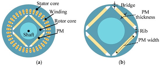
Figure 1.
The model of the HSPMM. (a) Integral structure and (b) rotor structure of the IPM motor.

Table 1.
Main stator parameters of the HSPMM.
3. Analysis of Rotor Parameter Influence on Electromagnetic and Mechanical Stress Performance
3.1. Pre-Treatment of Finite-Element Model
Ansys software (https://www.ansys.com/) is a large-scale general finite-element analysis (FEA) software developed by American Ansys Company, which can carry out electromagnetic, mechanical strength, thermal, acoustic, and fluid research. The electromagnetic and stress calculations in this paper are based on Ansys software. In this section, the 2D finite-element model (2D-FEM) was built in Ansys Workbench, as shown in Figure 2. The calculation of rotor stress is performed in the tool kit for static structures in the Ansys workbench, and the analysis of electromagnetic characteristics under no load and rated load is performed in the Maxwell module. During the analysis of the influence of rotor design parameters on motor performance, we kept the other parameters unchanged and changed only one parameter.
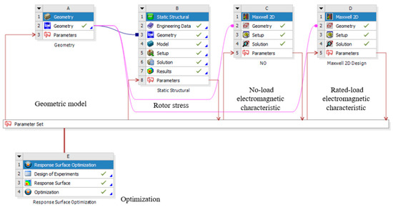
Figure 2.
The model of electromagnetic optimization.
The parametric model of the rotor structure is shown in Figure 3. The PM can be divided into two segments by one stiffener or into three segments by two stiffeners. The distance between the PM slots and the rotor outer diameter is called bridge thickness, THB. Stiffener thickness, THS, is the gap between three-segment PMs, that is, the sum of the thickness of two stiffeners. The rib width, WR, indicates the distance between the two PM slots. Combined with the preliminary analysis and design experience, the initial design rotor parameters are presented in Table 2.
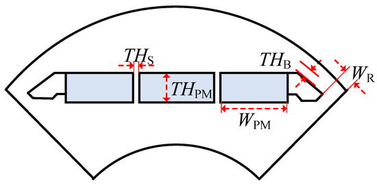
Figure 3.
IPM rotor structure with the three-segment PM.
Table 2.
Initial design parameters of the rotor.
3.1.1. Calculation Process of Rotor Stress
The calculation process of rotor stress for the high-speed IPM motor is consistent with the sequence of static structure of toolkit, which is mainly divided into four parts: adding materials, establishing geometric model, setup, and solution. The first step, add the materials required for the rotor stress calculation to the engineering date meter according to the material properties in Table 3. The second step is to link the motor model drawn in the geometry structure to the geometry module.
Table 3.
Rotor material properties.
The third step is setup. It mainly covers the settings of connections, mesh, boundary conditions, rotation speed, and thermal condition. In the pre-treatment of rotor stress simulation, the outer surface of the PMs is in bonded contact with the rotor core, and the inner surface of the PMs is set with frictional contact. The element size of rotor mesh is 1 mm, as shown in Figure 4. The rotor stress is simulated at a 120% rated speed (21,600 rpm) at a hot state (100 °C). The fourth step is solving. The equivalent stress of the rotor core is selected for calculation. The yield strength of electrical steel is 480 MPa, while the PM can withstand a compressive stress of 800 MPa. Therefore, all rotor stress distributions are discussed only in relation to the rotor core in this paper.
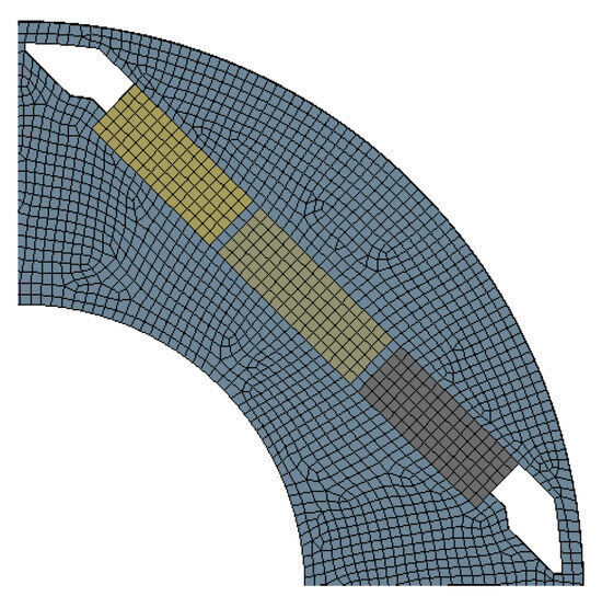
Figure 4.
The mesh of the rotor stress calculation model.
3.1.2. Calculation Process of Electromagnetic Characteristics
The electromagnetic calculation of the high-speed IPM motor is divided into no load and rated load, which are distinguished by the setting of the winding excitation. The pre-processing of electromagnetic calculation mainly includes establishing a geometric model, selecting the solution type, setting material, setting motion band, boundary condition, excitation source, and mesh.
In this paper, in the process of analyzing the influence of rotor design parameters on motor performance, the geometric model is changed by changing the parameters. The solution type of the 2D maxwell model selects transient. The addition of materials is divided into stator and rotor electrical steel materials, PM materials, and winding conductor materials. For models with moving parts, motion boundaries need to be set. For the HSPMM analyzed in this paper, select the center of the air gap to draw the motion boundary and add the axis of rotation, direction of rotation, and speed of rotation.
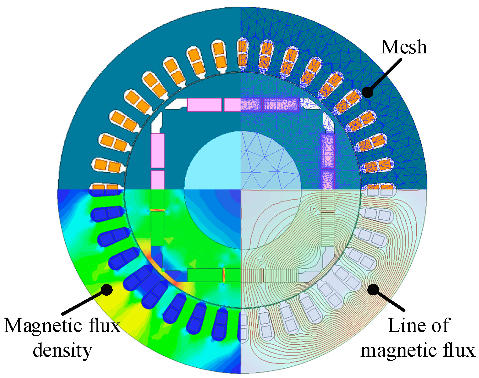
For the boundary conditions, vector potential is chosen because the whole model of the motor is used in this paper. That is, the outer vector magnetic potential of the boundary is a certain characteristic value (usually set to 0). In this paper, current sources are selected to excite the windings in the electromagnetic analysis process. The difference is that the magnitude of current during no-load electromagnetic analysis is set to 0, while the load simulation current is set to a three-phase rated current. Consistent with the rotor stress analysis process, the electromagnetic calculation process also requires the mesh of the motor model. The 2D-FEM of the electromagnetic calculation process is shown in Figure 5, including the mesh, magnetic flux density, and magnetic flux distribution. After finishing these pre-treatments, the electromagnetic model of the motor can be solved.

Figure 5.
The 2D-FEM of the electromagnetic calculation process.
3.2. Influence of Magnetic Bridge and Stiffeners Thickness
Designing a magnetic bridge is a challenge for high-speed IPM motors. As shown in Figure 6, the electromagnetic performance and rotor stress are compared for different bridge thicknesses. When the bridge thickness increases from 1 mm to 3 mm, the line back-EMF decreases from 382.6 V to 348 V. The maximum rotor stress decreases to 820 MPa, a 41% reduction compared to 1 mm. Figure 6c summarizes the variation trend of no-load line back-EMF and rotor stress at different bridge thicknesses.
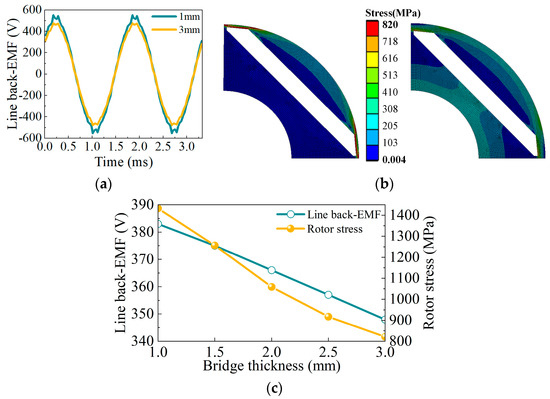
Figure 6.
The influence of the bridge thickness on back-EMF and stress. (a) Line back-EMF; (b) rotor stress; (c) variation trend.
Unfortunately, when the bridge thickness is 3 mm, the rotor stress is still greater than the yield strength of the electrical steel. Therefore, it is necessary to take measures to strengthen the rotor’s reliability. PM materials can be divided into three segments by adding stiffeners. As shown in Figure 7a, when the thickness of the stiffener is 2.5 mm, the maximum stress of the rotor structure is 425 MPa. Figure 7b summarizes the influence of the stiffener thickness on the no-load back-EMF.
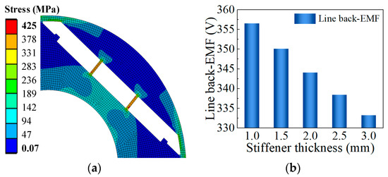
Figure 7.
The influence of the stiffener thickness on line back-EMF and rotor stress. (a) Rotor stress; (b) line back-EMF.
4. Sensitive Analysis of Rotor Parameters
4.1. Rotor Optimize Parameters
Five rotor design parameters are set as optimization variables in the optimization process, including bridge thickness, rib width, stiffener thickness, PM thickness, and PM width. Figure 8 shows the trend of the five optimization parameters for motor efficiency and rotor stress.
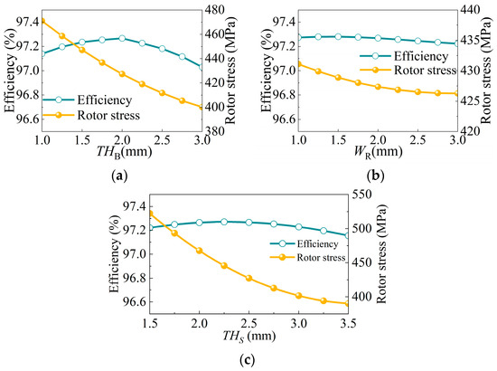
Figure 8.
The influence of each parameter on efficiency and rotor stress. (a) Bridge thickness; (b) rib width; (c) stiffener thickness.
In Figure 8a, when the bridge thickness is greater than 2.5 mm, the motor efficiency drops rapidly. However, the decreasing tendency of rotor stress becomes slow. Therefore, the variation range of the bridge thickness is limited from 1.0 mm to 2.5 mm. As can be seen from Figure 8b, the effect of rib width on motor efficiency is mild. The effect of stiffener thickness on motor efficiency and rotor stress is shown in Figure 8c. With the increase in the stiffener thickness, motor safety is greatly improved, but motor efficiency first increases and then decreases. In order to obtain higher motor efficiency, the variation range of stiffener thickness is set from 2.0 mm to 3.5 mm.
With the increase in the number of PMs, the efficiency of the motor increases, and the centrifugal force and rotor stress also increase. In addition, the number of PMs used is limited by the installation size. Therefore, the maximum and minimum values of PM thickness are set to 5.5 mm and 7 mm, respectively. The variation range of PM width is limited to 51–54 mm.
Based on the above analysis, the variation ranges of the five rotor design parameters are listed in Table 4.
Table 4.
Optimized design parameters and variation range.
4.2. Response Surface Analysis
The optimization model is built based on the Optimization toolkit in Ansys Workbench. Figure 9 summarizes the fitting accuracy of the Kriging surrogate model and 2D-FEM calculation results. The Kriging surrogate model is an unbiased estimation model that predicts the results of uncalculated test points on the basis of calculated test sample data. It can be seen that the predicted values are highly consistent with the calculated values. The response surface of rotor optimization parameters to motor performance is shown in Figure 10, Figure 11 and Figure 12.
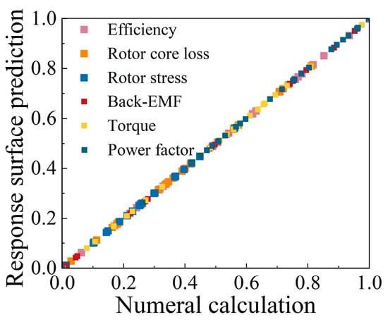
Figure 9.
Fitted curve of the predicted and calculated values.
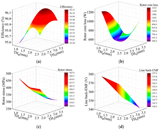
Figure 10.
Response surface of bridge thickness and stiffener thickness for motor performance. (a) Efficiency; (b) rotor core loss; (c) rotor stress; (d) line back-EMF.
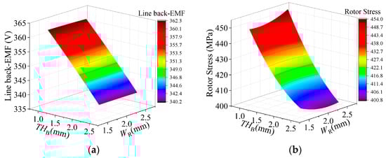
Figure 11.
Response surface of bridge thickness and rib width for motor performance. (a) Line back-EMF; (b) rotor stress.
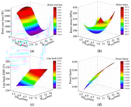
Figure 12.
Response surface of PM thickness and PM width for motor performance. (a) Rotor core loss; (b) rotor stress; (c) back-EMF; (d) power factor.
Figure 10 presents the effects of the bridge thickness and stiffener thickness on the efficiency, rotor core loss, rotor stress, and back-EMF. The efficiency of the motor first increases and then decreases with the increase in the bridge and stiffener thicknesses. The rotor core loss generally decreases with the increase in the bridge thickness. It can be seen from Figure 10c,d that the rotor stress and line back-EMF all decrease obviously with the increase in the bridge and stiffener thicknesses.
The influence of bridge thickness and rib width on line back-EMF and rotor stress is displayed in Figure 11. It is obvious that bridge thickness has a greater impact on motor performance. Figure 12 illustrates the effects of PM thickness and width on motor performance. The rotor core loss generally decreases with the increase in PM thickness. With the increase in the number of PMs, the rotor stress, no-load back-EMF, and power factor all increase significantly.
4.3. Sensitivity Analysis
The above analysis shows that each parameter has a different degree of influence on motor performance. Sensitivity analysis is an effective way to evaluate the impact of individual parameters on optimization objectives [24]. In this optimization, the Pearson correlation coefficient is chosen to define sensitivity [25]. As shown in (1):
where is the value of the optimization objective corresponding to the optimization variable , is the average of the optimization objective when the parameters take different values. n is the sample size.
The histogram in Figure 13 shows the sensitivity coefficient of this optimization objective. A positive value means that the optimization objective increases with the increase in the optimization variable [26]. From the analysis results of Figure 13, it can be seen that different rotor optimization parameters have different sensitivities to motor characteristics. For example, PM thickness has a significant influence on the efficiency and rotor core loss of the motor. The stiffener thickness has a relatively large influence on rotor stress. In contrast, the influence of rib width on motor performance is modest.
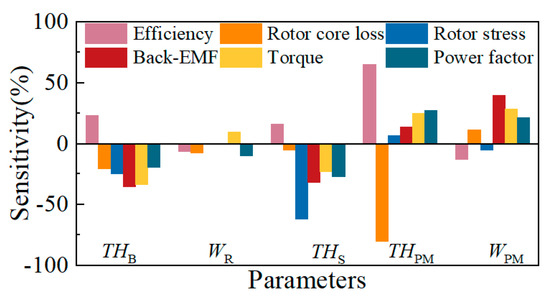
Figure 13.
Sensitivity values for optimization parameters.
5. Comprehensive Optimization
5.1. Optimization Process
The detailed optimization flowchart is summarized in Figure 14, which mainly includes the following four steps:
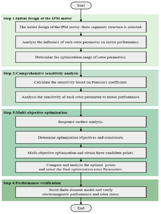
Figure 14.
Flowchart of the optimization.
Step 1: Initial design of the IPM motor. Firstly, the rotor structure of the three-segment PM is adopted by analysis. Then, five optimization variables are selected. Finally, the influence of five variables on motor efficiency and rotor stress is analyzed to determine the variation range.
Step 2: Comprehensive sensitivity analysis. Firstly, the sensitivity of rotor variables to motor characteristics is calculated based on the Pearson coefficient. Then, the effect of each parameter on multi-physics performance is analyzed and evaluated with sensitivity coefficients.
Step 3: Multi-objective optimization. Firstly, the surrogate model for rotor design parameters and motor performance is established. Secondly, the optimization objectives and constraints are reasonably selected. Then, the multi-objective genetic algorithm is used to achieve the optimal solutions. Finally, select the final optimization parameters.
Step 4: Performance verification. In this step, the electromagnetic performance, mechanical stress, and temperature distribution of the initial scheme and the optimized design are compared. And the reliability and safety of the optimization design are tested and verified by experiments.
5.2. Optimization Objectives and Constraints
In order to make the selection of optimization objectives and constraints more reasonable, it is essential to analyze and consider the characteristics of multiple physical fields, including mechanical strength, electromagnetic properties, and temperature distribution [27]. Due to small size and difficult heat dissipation conditions, the maximum motor efficiency is set as the first optimization goal to obtain a more reasonable temperature distribution.
In addition, when the motor efficiency is the same, different loss distributions have a great impact on the motor temperature distribution of the high-speed IPM motor. The housing water cooling system is used for heat dissipation design. The heat dissipation conditions of the stator are good because it is close to the spiral waterway.
On the premise of keeping the total iron loss constant at 4 kW, only the iron loss distribution ratio between the stator and rotor is adjusted. This change means that the iron loss of the stator or rotor may increase, while the iron loss on the other side will decrease accordingly, but the sum of the two will always be maintained at 4 kW. The effect of different rotor losses on motor temperature is shown in Figure 15. When the rotor core loss increases, the temperature of the stator core remains basically unchanged. The temperature of the stator core decreases by 2%. However, the temperature of the rotor core and PM increased significantly, by 33.1% and 29.8%, respectively. It can be concluded that the influence of rotor core loss on temperature is serious. Therefore, the minimum rotor core loss is set as the second optimization objective to guarantee the lowest motor temperature.
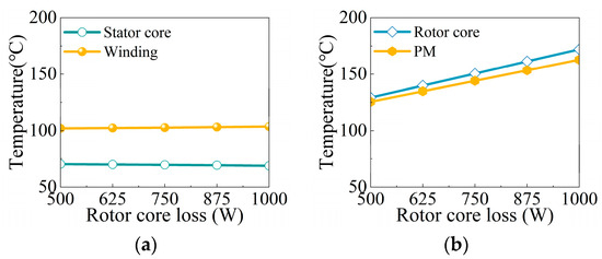
Figure 15.
The influence of rotor loss on temperature. (a) Stator; (b) rotor.
The constraints of the high-speed IPM motor optimization process include rotor stress, no-load line back-EMF, output torque, and power factor.
Rotor stress: To ensure the mechanical reliability, the maximum stress of the rotor core must be less than the maximum yield strength of the rotor material (480 MPa) and leave a certain safety margin (85%).
No-load electromagnetic characteristics: No-load line back-EMF is an important indicator of no-load performance. To achieve a higher power factor, the line back-EMF should be close to the rated voltage, which is limited to between 360 V and 380 V.
Rated-load electromagnetic performance: Torque should be greater than the rated torque (74.2 N·m). In addition, the power factor is limited to above 0.95.
Summarizing the above analysis, the two optimization objectives and four constraints of the IPM motor are listed as follows:
where is the efficiency, and is the rotor core loss. is rotor stress, is the no-load line back-EMF, the output torque, and cos Φ is the power factor.
Genetic algorithm has been recognized as an effective optimization method, and this method has been verified in many related papers. Thus, in this paper, genetic algorithms are employed in order to obtain optimized solutions based on response surface models. The electromagnetic optimization uses the multi-objective genetic algorithm to obtain Pareto solutions. During multi-objective optimization, the optimal solution is a compromise between two objectives. The four subplots in Figure 16 all show the relationship between multi-objective performances during optimization.

Figure 16.
Relationship between multi-objective performances.(a) Relationship between back-EMF, efficiency and rotor stress; (b) Relationship between rotor core loss, efficiency and rotor stress; (c) Relationship between power factor, efficiency and rotor stress; (d) Relationship between output torque, efficiency and rotor stress.
5.3. Optimization Results
The three candidate points selected from the Pareto front are compared in Table 5. It is clear that the overall performance of the third candidate is better than the other two designs.
Table 5.
Optimized design parameters and HSPMM performance.
6. Performance Comparison
In this section, the final optimization parameters are decided. Then, the initial and optimized schemes are compared, including electromagnetic performance, rotor stress, and temperature distribution. The final design is presented in Table 6 by combining the third candidate and actual processing requirements.
Table 6.
Initial and optimized rotor parameters.
6.1. Comparison of Electromagnetic Performances
Figure 17 presents the electromagnetic performance of the motor under no-load conditions. The magnetic flux density distribution and flux line distribution are calculated. As shown in Figure 17a, the magnetic flux density of both schemes is mainly concentrated at the magnetic bridge and stiffeners. The no-load line back-EMF of the initial design is 345 V, while that of the optimized motor is 366.5 V.
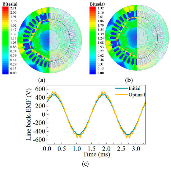
Figure 17.
Comparison of the no-load electromagnetic performance before and after optimization. (a,b) Magnetic flux density; (c) line back-EMF.
The torque and rotor core losses for the rated load are shown in Figure 18. It can be seen from Figure 18a that the optimized average torque increases slightly from 76.2 N·m to 78.3 N·m. In Figure 18b, the optimized rotor core loss drops to 538 W, a reduction of 355 W compared to the initial design. The decrease in rotor core losses indicates that the temperature distribution of the optimized motor will have a significant improvement.
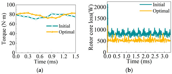
Figure 18.
Comparison of the rated-load motor performances before and after optimization. (a) Torque; (b) rotor core loss.
6.2. Comparison of Rotor Stress
Figure 19 shows the rotor stress distribution before and after optimization. The maximum rotor stress of the optimized motor is 373 MPa; the safety factor is 1.29, which is calculated by dividing the yield stress by the maximum stress generated [28].
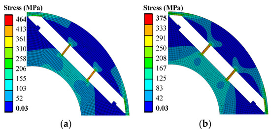
Figure 19.
Comparison of the rotor stress before and after optimization. (a) Initial; (b) optimal.
6.3. Comparison of Temperature Distribution
A suitable heat dissipation system must be used to ensure rotor safety and reliability. In this paper, the temperature distribution of the high-speed IPM is simulated using the thermal network method in motor-CAD. As shown in Figure 20, a water cooling system with a spiral waterway outside the stator is adopted; the water temperature and flow rate are set to 25 °C and 1.2, respectively. The direction of the arrows in the figure represents the direction of flow of the cooling liquid.
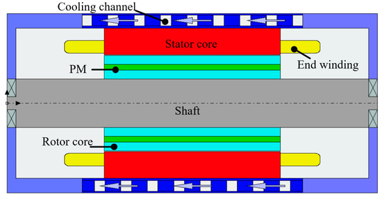
Figure 20.
Motor cooling system design.
The temperature distributions of the initial design and optimized scheme are shown in Figure 21. For the high-speed IPM motors, the maximum temperature of the motor is located at the rotor core. The maximum motor temperature of the optimized scheme is 129.6 °C, which is 37.1 °C lower than the original design. The temperature of the PM decreased from 158.7 °C to 125.3 °C, a decrease of 33.4 °C.
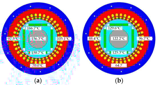
Figure 21.
Comparison of temperature before and after optimization. (a) Initial; (b) optimal.
The comparisons of the detailed performance between the initial and optimized schemes are listed in Table 7. Compared to the initial design, the optimized motor performance is significantly improved in all aspects. Among them, motor efficiency increases from 95.96% to 96.34%, with an increase of 0.38%. The optimized power factor rises to 0.972. The rotor safety factor increases from 1.03 to 1.29. In addition, the temperature of the winding decreases from 105.1 °C to 96.7 °C.
Table 7.
Initial and optimized motor performance.
7. Prototype and Experiment
The optimized motor has good electromagnetic performance and high mechanical reliability. Thus, a 140 kW, 18,000 rpm high-speed IPM motor is manufactured based on the optimized scheme. The photo of the prototype is shown in Figure 22. In order to better confirm the simulation analysis, the performance of the prototype is verified, including rotor safety, electromagnetic, and temperature tests.
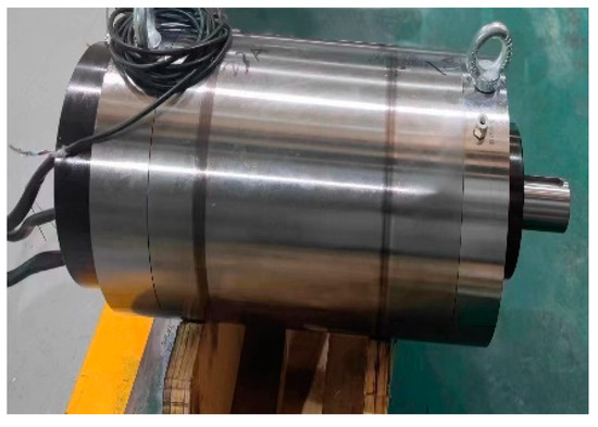
Figure 22.
The prototype.
Rotor stress is the primary factor affecting rotor reliability. In the test experiment of rotor safety, the rotor is run at a 120% rated speed for 30 min. It is found that there is no deformation or damage after removing the rotor. The no-load line back-EMF is measured with the prototype driven by another motor. The power factor of the prototype is obtained by the power analyzer. The test result is 0.969, which is slightly lower than the optimization analysis result. The efficiency of the prototype obtained by the ratio of output power and input power is 96.18%, which is very close to the optimization result. Moreover, the winding temperature is measured by a temperature sensor in the end winding, after the motor has been running in the rated state for several hours.
8. Conclusions
In this paper, an electromagnetic optimization design of a 140 kW, 18,000 rpm high-speed IPM motor is carried out. On the one hand, the mechanical strength of the rotor was taken into account in the optimization process. On the other hand, in order to obtain a more reasonable temperature distribution, the maximum motor efficiency and the minimum rotor core loss are selected as the optimization objectives.
Compared with the initial design, the motor efficiency was increased by 0.38%, and the rotor safety factor was increased by 25.2%. The temperature of the PM drops by 33.4 °C. Based on the above results, the electromagnetic performance, rotor stress, and temperature distribution of the motor are significantly improved. Finally, a 140 kW, 18,000 rpm high-speed IPM motor is manufactured based on the optimized design. The experimental results are in good agreement with the theoretical analysis, which proves the effectiveness of the electromagnetic optimization design.
Author Contributions
Conceptualization, F.Y. and G.D.; methodology, F.Y. and N.L.; software, N.L.; validation, F.Y., G.D., M.H. and Z.K.; formal analysis, N.L.; investigation, F.Y. and N.L.; resources, F.Y.; data curation, F.Y. and N.L.; writing—original draft preparation, N.L.; writing—review and editing, F.Y., G.D., M.H. and Z.K.; visualization, N.L.; supervision, G.D.; project administration, F.Y.; funding acquisition, G.D. All authors have read and agreed to the published version of the manuscript.
Funding
This research was funded by the National Natural Science Foundation of Shaanxi Province, grant number 2024JC-YBMS-419. This research was funded by the China Postdoctoral Science Foundation, grant number 2021M693880. This research was funded by the National Natural Science Foundation of Shaanxi Province, grant number 2019JQ-792. This research was funded by the Key Research and Development Program of Shaanxi, 2024GX-YBXM-243.
Institutional Review Board Statement
Not applicable.
Informed Consent Statement
Not applicable.
Data Availability Statement
The original contributions presented in the study are included in the article, further inquiries can be directed to the corresponding author.
Conflicts of Interest
Author Zhen Kang was employed by the company Xi’an Thermal Power Research Institute Co., Ltd. The remaining authors declare that the research was conducted in the absence of any commercial or financial relationships that could be construed as a potential conflict of interest.
References
- Liu, F.; Wang, X.H.; Xing, Z.Z.; Ren, J.; Li, X. Analysis and research on no-load air gap magnetic field and system multiobjective optimization of interior PM motor. IEEE Trans. Ind. Electron. 2022, 69, 10915–10925. [Google Scholar] [CrossRef]
- Li, L.N.; Zhu, G.J. Electromagnetic-Thermal-Stress Efforts of Stator-Casing Grease Buffers for Permanent Magnet Driving Motors. IEEE Trans. Ind. Appl. 2024, 60, 1268–1276. [Google Scholar] [CrossRef]
- Du, G.H.; Huang, N.; He, H.C.; Lei, G.; Zhu, J.G. Parameter design for a high-speed permanent magnet machine under multiphysics constraints. IEEE Trans. Energy Convers. 2020, 35, 2025–2035. [Google Scholar] [CrossRef]
- Qin, X.F.; Yao, L.; Wan, W.J.; Shi, D.; Wang, Y.C.; Shen, J.X. Investigation of bessel functions in analytical modeling of rotor eddy current losses in PM machine rotor with copper shield. IEEE Trans. Magn. 2023, 59, 8100609. [Google Scholar] [CrossRef]
- Du, G.H.; Li, N.M.; Zhou, Q.X.; Gao, W.T.; Wang, L.; Pu, T. Multi-physics comparison of surface-mounted and interior permanent magnet synchronous motor for high-speed applications. Machines 2022, 10, 700. [Google Scholar] [CrossRef]
- Wang, J.; Geng, W.W.; Li, Q.; Li, L.; Zhang, Z.R. A new flux-concentrating rotor of permanent magnet motor for electric vehicle application. IEEE Trans. Ind. Electron. 2022, 69, 10882–10892. [Google Scholar] [CrossRef]
- Peng, C.; Wang, D.H.; Feng, Z.K.; Wang, B.D. A new segmented rotor to mitigate torque ripple and electromagnetic vibration of interior permanent magnet machine. IEEE Trans. Ind. Electron. 2022, 69, 1367–1377. [Google Scholar] [CrossRef]
- Yang, Y.Y.; Castano, S.; Yang, R.; Kasprzak, M.; Bilgin, B. Design and comparison of interior permanent magnet motor topologies for traction applications. IEEE Trans. Transp. Electrific. 2017, 3, 86–97. [Google Scholar] [CrossRef]
- Abdelrahman, A.; Sahu, A.; Emery, N.; Al-Ani, D.; Bilgin, B. Multi-physics design platform for a high power density multi-phase IPM traction motor: Analysis and simulation. In Proceedings of the 2022 IEEE Transportation Electrification Conference & Expo (ITEC), Anaheim, CA, USA, 15–17 June 2022; pp. 92–96. [Google Scholar]
- Xu, Y.M.; Ai, M.M.; Xu, Z.Y.; Liu, W.H.; Wang, Y.D. Research on interior permanent magnet synchronous motor based on performance matching of electric bus. IEEE Trans. Appl. Supercond. 2021, 31, 5204304. [Google Scholar] [CrossRef]
- Chai, F.; Li, Y.; Liang, P.X.; Pei, Y. Calculation of the maximum mechanical stress on the rotor of interior permanent-magnet synchronous motors. IEEE Trans. Ind. Electron. 2016, 63, 3420–3432. [Google Scholar] [CrossRef]
- Li, Y.; Pei, Y.L.; Liang, P.X.; Chai, F. Analysis of the rotor mechanical strength of interior permanent magnet synchronous in-wheel motor with high speed and large torque. In Proceedings of the 2014 IEEE Conference and Expo Transportation Electrification Asia-Pacific (ITEC Asia-Pacific), Beijing, China, 31 August–3 September 2014; pp. 1–5. [Google Scholar]
- Jung, J.W.; Lee, B.H.; Kim, D.J.; Hong, J.P.; Kim, J.Y.; Leon, S.M.; Song, D.H. Mechanical stress reduction of rotor core of interior permanent magnet synchronous motor. IEEE Trans. Magn. 2012, 48, 911–914. [Google Scholar] [CrossRef]
- Rao, J.; Qu, R.H.; Ma, J.; Xu, W. Investigate the influence of magnetic bridge design on mechanical strength and electromagnetic characteristics in high speed IPM machines. In Proceedings of the 2014 17th International Conference on Electrical Machines and Systems (ICEMS), Hangzhou, China, 22–25 October 2014; pp. 22–27. [Google Scholar]
- Chu, G.Y.; Dutta, R.; Rahman, M.F.; Lovatt, H.; Sarlioglu, B. Analytical calculation of maximum mechanical stress on the rotor of interior permanent-magnet synchronous machines. IEEE Trans. Ind. Appl. 2020, 56, 1321–1331. [Google Scholar] [CrossRef]
- Du, G.H.; Huang, N.; Zhao, Y.Y.; Lei, G.; Zhu, J.G. Comprehensive sensitivity analysis and multiphysics optimization of the rotor for a high speed permanent magnet machine. IEEE Trans. Energy Convers. 2021, 36, 358–367. [Google Scholar] [CrossRef]
- Jung, Y.-H.; Park, M.-R.; Kim, K.-O.; Chin, J.-W.; Hong, J.-P.; Lim, M.-S. Design of high-speed multilayer IPMSM using ferrite PM for EV traction considering mechanical and electrical characteristics. IEEE Trans. Ind. Appl. 2021, 57, 327–339. [Google Scholar] [CrossRef]
- Lin, R.; Sudhoff, S.D.; Nascimento, V.C.D. A multi-physics design method for V-shape interior permanent-magnet machines based on multi-objective optimization. IEEE Trans. Energy Convers. 2020, 35, 651–661. [Google Scholar] [CrossRef]
- Praslicka, B.; Ma, C.; Taran, N. A computationally efficient high-fidelity multi-physics design optimization of traction motors for drive cycle loss minimization. IEEE Trans. Ind. Appl. 2023, 59, 1351–1360. [Google Scholar] [CrossRef]
- Liu, F.; Wang, X.H. Design and multiobjective optimization of dual-circulation cooling system considering electro-thermal coupling for IPMSM. IEEE Trans. Transp. Electrific. 2023, 9, 3072–3084. [Google Scholar] [CrossRef]
- Sun, X.D.; Shi, Z.; Lei, G.; Guo, Y.G.; Zhu, J.G. Multi-objective design optimization of an IPMSM based on multilevel strategy. IEEE Trans. Ind. Electron. 2021, 68, 139–148. [Google Scholar] [CrossRef]
- Tahkola, M.; Keränen, J.; Sedov, D.; Far, M.F.; Kortelainen, J. Surrogate modeling of electrical machine torque using artificial neural networks. IEEE Access 2020, 8, 220027–220045. [Google Scholar] [CrossRef]
- Li, Z.; Che, S.; Zhao, H.; Zhang, L.C.; Wang, P.J.; Du, S.H.; Zhang, H.J.; Feng, Y.F.; Sun, H.X. Loss analysis of high-speed permanent magnet motor based on energy saving and emission reduction. Energy Rep. 2023, 9, 2379–2394. [Google Scholar] [CrossRef]
- Chen, H.; Lee, C.H.T. Parametric sensitivity analysis and design optimization of an interior permanent magnet synchronous motor. IEEE Access 2019, 7, 159918–159929. [Google Scholar] [CrossRef]
- Geng, W.W.; Wang, J.; Li, L.; Guo, J. Design and multiobjective optimization of a new flux-concentrating rotor combining halbach PM array and spoke-type IPM machine. IEEE Trans. Mechatron. 2023, 28, 257–266. [Google Scholar] [CrossRef]
- Lim, D.K.; Yi, K.P.; Jung, S.Y.; Jung, H.K.; Ro, J.S. Optimal design of an interior permanent magnet synchronous motor by using a new surrogate-assisted multi-objective optimization. IEEE Trans. Magn. 2015, 51, 8207504. [Google Scholar]
- Praslicka, B.; Taran, N.; Ma, C. An ultra-fast method for analyzing IPM motors at multiple operating points using surrogate models. In Proceedings of the 2022 IEEE Transportation Electrification Conference & Expo (ITEC), Anaheim, CA, USA, 15–17 June 2022; pp. 868–873. [Google Scholar]
- Ahn, J.H.; Han, C.; Kim, C.W.; Choi, J.Y. Rotor design of high-speed permanent magnet synchronous motors considering rotor magnet and sleeve materials. IEEE Trans. Appl. Supercond. 2018, 28, 5201504. [Google Scholar] [CrossRef]


Disclaimer/Publisher’s Note: The statements, opinions and data contained in all publications are solely those of the individual author(s) and contributor(s) and not of MDPI and/or the editor(s). MDPI and/or the editor(s) disclaim responsibility for any injury to people or property resulting from any ideas, methods, instructions or products referred to in the content. |
© 2024 by the authors. Licensee MDPI, Basel, Switzerland. This article is an open access article distributed under the terms and conditions of the Creative Commons Attribution (CC BY) license (https://creativecommons.org/licenses/by/4.0/).