Article

A Novel Method of Time-Varying Formation Control Based on a Directed Graph for Multiple Autonomous Underwater Vehicles

1
National Key Laboratory of Science and Technology on Underwater Vehicle, Harbin Engineering University, Harbin 150001, China
2
State Key Laboratory of Robotics, Shenyang Institute of Automation, Chinese Academy of Sciences, Shenyang 110016, China
3
Key Laboratory of Marine Robotics, Shenyang 110169, China
*
Author to whom correspondence should be addressed.
Appl. Sci. 2024, 14(14), 6377; https://doi.org/10.3390/app14146377
Submission received: 20 June 2024 / Revised: 15 July 2024 / Accepted: 17 July 2024 / Published: 22 July 2024
(This article belongs to the Special Issue Modeling, Guidance and Control of Marine Robotics)

Abstract

:
Currently, autonomous underwater vehicles (AUVs) are facing various challenges, rendering multiple-AUV (multi-AUV) formation control a pivotal research direction. The issues surrounding formation control for a multi-AUV system to establish time-varying formations must be investigated. This paper discusses the formation protocol of multi-AUV systems in order to establish the defined time-varying formations. First, when these systems establish formations, the speed of each AUV can be equivalent. After that, consensus-based methods are used to solve the time-varying formation-control problem. The necessary and sufficient process of multi-AUV in achieving time-varying formations is proved. Furthermore, the formula for the time-varying formation center function is provided. Further, we present a protocol law for multi-AUVs to establish time-varying formations. Finally, the theoretical results of a simulation are presented, which validate the formation protocol.

1. Introduction

The autonomous underwater vehicle (AUV) is a highly sophisticated, intricate system that integrates various cutting-edge technologies, such as vehicle control, anomaly detection, information decision-making, and deep-sea navigation. This convergence of advanced technologies enables the AUV to operate efficiently in challenging underwater environments. One significant advantage of the AUV is its ability to cover a larger search area. By utilizing its autonomous capabilities, the AUV can navigate through vast expanses of the ocean floor with precision and speed. This expanded coverage allows for more comprehensive data collection and exploration of previously uncharted territories. Moreover, by employing multiple AUVs in coordinated missions, the fault tolerance of the entire system can be significantly improved. When one AUV encounters technical issues or malfunctions during an operation, other vehicles within the multiple-AUV (multi-AUV) fleet can seamlessly take over its tasks without disrupting overall mission objectives. This redundancy ensures continuous data acquisition and minimizes potential downtime due to equipment failures. Furthermore, advancements in communication systems have enhanced collaboration among multiple AUVs operating together. These vehicles can exchange real-time information regarding their respective positions, collected data, and environmental conditions. Such seamless communication facilitates efficient coordination between individual units within a multi-AUV team while optimizing resource allocation for maximum productivity.
In formation control, the leader–follower method of multiple agents is the most common structure. In this method, each follower aircraft is controlled to maintain its velocity and position to a predefined leader aircraft along the trajectory. This structure rapidly reconfigures and extends to new objects, so it can be quickly copied by other multi-AUVs [1]. Therefore, the leader-follower method is widely employed in real-world engineering problems. However, the formation system is too reliant on the leader. One team [2] studied multi-agent systems with input delays and found that parameters were too wide and difficult to adjust in the real marine environment. Others investigated the formation-control problem of leader–follower-structured AUVs through state-prediction estimation in the scenario of an undependable underwater acoustic channel [3]. Ultimately, the team conducted a comparison of the suggested formation-control strategy with the traditional method, and they proved the effectiveness of the former. Targeting the control problem of AUV formation with delays and interruption in the communication, another team [4] signed a feedback linearization controller and the PD control method, and they transformed the strongly coupled nonlinear vehicle model into a second-order model. Another team [5] proposed a basic formation-control system that could minimize the modifications of standardization among an autonomous surface vehicle and AUVs, and they tested it in a sea environment. Furthermore, researchers examined the leader–follower coordination control problem that arises in a continuous-time multi-AUV formation containing two independent topologies and time-varying delays [6,7]. Using the gradient-descent strategy to approximate the communication delay, a time-lag estimator was designed [8]. They found that the time lag of the leader AUV state packets reduced the actual delay, and that the formulation of the estimator led to obstacle avoidance. Additionally, researchers studied the leader–follower consistency problem of a multi-intelligent body system with input delays [2]. Others [9] studied synchronous state information, proposed a leader–follower consensus control protocol with time-varying delays, and performed a controllability analysis using Lyapunov–Krasovskii functionals. Expanding the research on the leader–follower consensus, one team [10] evaluated the issues of the immeasurable states of intelligent agents and the inherent time delays in the signal-transmission process. They subsequently created an unknown input observer to estimate time delays and established a consensus control protocol for multi-agent systems according to the observer’s estimated values. Moreover, one team [11] examined a novel optimal control method that can achieve the consensus of multiple AUVs and avoid obstacles with minimal control effort. Another team [12] focused on collision-free formation-tracking AUVs under the influence of compound disturbances in intricate ocean environments. To that end, they proposed a novel finite-time extended state observer (FTESO)-based distributed dual closed-loop model-predictive control scheme. In [13], the authors designed a control protocol based on a distributed robust model-predictive control to better coordinate cooperation between AUVs. In [14], the researchers established a robust model-predictive control scheme based on the active disturbance-rejection control strategy for the Untracking task. Of course, extending the use of these systems to multi-AUV systems can be challenging, as it involves orchestrating the control behavior of each subsystem and making sure that the local MPC (Model Predictive Control) optimization problem maintains its closed-loop stability under system constraints. In [15], the authors presented an unprecedented solution to the issue posed by the need to control the nonplanar multi-AUV formation reconfiguration. The proposed method utilizes the graph rigidity and affine transformation (GR-AT) approach, which can tackle this complex problem in a unique manner. In [16], the researchers established the distance rigid graph-based formation-control strategy for vehicles modeled with Euler–Lagrange-like (E-L) equations. The approach differs from linear systems due to the nonholonomic constraint in the former method. Furthermore, researchers [17] suggested a time-varying strategy based on optimization for networked uncertain Euler–Lagrange mobile agents. This strategy adaptively and flexibly considers objective functions that can change in real time, enabling its versatile application. Others [18] investigated the distance-based formation-control problem for multi-agent systems in arbitrary dimensional space. The agents are treated as point masses with dynamics governed by single and double integrators. In addressing rigid graph-based formation acquisition control problems, one team [19] focused on a class of double-integrator multiagent systems operating in two independent layers. This research illuminated how to acquire formations efficiently within such systems. Also, the work presented in [20] studied the formation coordination control of discrete-time distributed leaderless multi-AUV systems with two independent position–velocity communication topology and control inputs on a nonconvex set. Its focus was how to effectively coordinate multiple AUVs without relying on centralized leadership or global information exchange. In [21], the authors addressed the formation-control problem to deploy a group of AUVs by considering vehicle nonholonomic constraints and obstacle avoidance in the environment. In [22], the authors suggested a fixed-time-based method involving a multi-AUV leader–follower formation-control, achieving the finite-time convergence of formation-tracking error. In [23], the researchers created a two-loop controller to regulate multi-AUV formation, as well as a neural-network based controller and a conditional integrator to tackle model uncertainty and disturbances. In [24], the researchers proposed a new distributed control protocol for solving the guaranteed cost formation tracking control of multi-AUVs with switching topology communication. The protocol realizes formation tracking control of a multi-AUV system, and considers the characteristics of switching topology communication between individuals. In [25], the researchers designed a method of formation control that combines CNN-LSTM (Convolutional Neural Networks-Long Short-Term Memory) prediction and backsteps sliding mode control to overcome hydroacoustic communication constraints in the multi-AUV leader–follower formation. In [26], the researchers transformed the nonlinear AUV model into a second-order integral model via feedback linearization. They designed finite-time sliding-mode disturbance observers for unknown disturbances in the ocean and then estimated the unknown disturbances in finite time.
In [27], a fixed-time terminal sliding mode control method was designed for a class of second-order nonlinear systems with unknown dynamics and perturbations. The results of this study were subsequently applied in [28] to achieve consistency control. To enhance convergence speed, Ni et al. [29] improved the fixed-time stable system proposed in [27] by deriving a smaller upper bound for convergence time. They then applied the result to the second-order system discussed in [30], considering the input delay problem, and designed a fixed-time control strategy by using the leader–following mechanism. Building upon the abovementioned work, ref. [31] further improved the convergence speed and investigated a solution for handling the singularity problem of the sliding mode surface. References [30,32,33] transform the delay error system into a second-order system without delay for double integral and first-order linear multi-agent systems with determined input delay, and they use the fixed-time reaching law to achieve fixed-time consistency. In [34], the focus shifts to predicting the future time states of time-varying input delay single integral systems while carefully considering the uncertainties inherent in the transformed systems. Here, nonlinear fixed-time formation protocols for multi-robot systems in both directed and undirected topologies are proposed. In addition, in [33], drawing inspiration from the integral predictor in [35], a predictor was designed to predict the future state for a first-order nonlinear multi-agent system characterized by uniformly fixed input delay and uncertainties. Ref. [36] investigated the cooperative trajectory tracking (CTT) control problem of multiple autonomous underwater vehicles (AUVs), and designed a neural network-based data-driven control algorithm and used the radial basis function neural network to estimate the primary pseudo parameters. Ref. [37] developed a new MRMP (Multi-Robot Motion Planning) algorithm. The fitness for these variants was also measured for simulations where different target motion models were used when calculating the fitness function, highlighting the improved performance when using actual target motion models. Ref. [38] studied a novel reference filter for the Formation Keeping (FK) of multiple AUVs; the FK objectives were treated as servo-constraints. The reference values for the motion control can be directly computed using the Udwadia–Kalaba equation. A low-level Model Predictive Control (MPC) is assumed to be embedded to each agent. The existing limitations in their communication are also considered. Results verified the trajectory tracking and disturbance rejection, with low constraint violations. Ref. [39] studied a group of heterogeneous AUV systems with intermittent communication links being considered, as well as a finite-time trajectory-tracking control strategy; a distributed trajectory-tracking controller was designed using the states estimated by the intermittent communication network, even without velocity measurements. A homogeneous technique was utilized to prove that all followers can track the leader in a finite time. Finally, the effectiveness of the developed finite-time tracking control strategy is illustrated by numerical simulations. Ref. [40] addresses significant control challenges, including external disturbances, noise, model uncertainties, actuator faults, stochastic switching topologies, time-varying communication delays, and positional information between agents. Stochastic switching topologies are assumed to follow a Markov chain. The proposed framework demonstrates its effectiveness in managing the high nonlinearity and coupled dynamics of AUVs.
This paper investigates the problem of achieving time-varying formations based on the consensus for multi-AUVs. First, the focus is on time-varying formations, which are essential in practical applications where certain formations require agents to have different speeds, such as rotation formations. Only time-varying formations can effectively address this scenario. Second, we present an analysis of AUV formation and the design protocol for multi-AUV systems, aiming to establish time-varying formations. To do so, we propose the necessary and sufficient conditions for these formations. Third, the explicit formula of the AUV formation center functions is provided. Lastly, the theoretical results of simulations are presented.
The rest of this paper is organized as follows. In Section 2, basic concepts and the problem are presented. In Section 3, the main theoretical analysis is presented. In Section 4, three typical working conditions verified by a simulation are presented. Furthermore, Section 5 gives the conclusions and discussion.

2. Background Description

Here, the model of AUV and the basic concepts about graph theory are introduced.

2.1. Basic Concepts

A directed graph G = Q , ε , W consists of a set of nodes Q = q 1 , q 2 , , q n , a set of edges ε q i , q j : q i , q j Q , and a weighted adjacency matrix W = w i j N × N with nonnegative elements w i j . An edge of G is denoted by e i j = q i , q j . Then, if and only if e i j ε and w i i = 0 for all i 1 , , N , the w i j > 0 . The set of neighbors of node q i is denoted by N i = q j Q : q i , q j ε . The in-degree of node q i is defined as deg i n q i = j = 1 N w i j . The degree matrix of G is denoted by D = diag deg i n q i , i = 1 , 2 , N . The Laplacian matrix of G is d L = D W .
Further information about graph theory can be obtained from [41].
For a given Ψ , Re Ψ and Im Ψ represent the real and the imaginary part of Ψ , respectively. The superscript H denotes the Hermitian adjoint of matrices.
The following lemma is useful for multi-AUV systems.
Lemma 1. 
Define  L N × N  is the Laplacian matrix of a directed graph  G [42]:
(1)
L  has at least one zero eigenvalue, and  1 N  is the associated eigenvector; that is,  L 1 N = 0 ;
(2)
If  G  has a spanning tree, then  0  is a simple eigenvalue of  L and all the other  N 1  eigenvalues have positive real parts;
1 N  means a column vector of size  N  with 1 as its elements, and  I n  means an identity matrix with n dimensions;
0  means zero matrices of an appropriate size, with zero vectors and zero number as special cases.

2.2. Mathematical Model of the AUV

The AUV design in this study is a six-DOF (Degree of Freedom) navigation in water; moreover, we also took into account the actual application situation and the type of sensor equipped, as well as the fact that the AUV actually navigates at the same depth. Thus, we simplified the entire control model such that the AUV formation moves on the horizontal plane (Figure 1). The designed AUV has two horizontal channels to realize the change in the head direction, so the AUV in the plane space is fully driven, and the kinematics and dynamics formulas [25] are as follows:
η ˙ = J ψ υ M υ ˙ = Γ η , υ + τ + d Δ f ,
where η is a state vector for the AUV, and η = x , y , ψ T , where x is the portrait position, y is the lateral position, and ψ is the bow direction angle. Additionally, υ = u , v , r T , where u is the speed along X, v is the speed along Y, and r is the bow angular velocity. Finally, τ = τ 1 , τ 2 , τ 3 T , where τ is the control input vector to be designed, τ 1 is the forward force, τ 2 is the transverse force, and τ 3 is the yawing moment.
J φ is the bow’s rotation matrix, defined as follows:
J ψ = cos ψ sin ψ 0 sin ψ cos ψ 0 0 0 1
J ˙ ψ = J ψ S r
J T ψ S r J ψ = J ψ S r J T ψ = S r
S r = 0 r 0 r 0 0 0 0 0
Let
d = M J T δ ,
δ = δ 1 , δ 2 , δ 3 ,
ϑ = ϑ 1 , ϑ 2 , ϑ 3 is uncertainty of the model
Γ η , υ = C υ υ D υ ,
where C υ is the Coriolis force and centripetal force matrix, D is the damping coefficient matrix, and M is the inertia coefficient matrix. The port and starboard structure of the AUV is symmetrical, so Y r ˙ = N v ˙ , and the geometric center of the AUV coincides with its center of gravity; thus, x g = 0 :
M = m X u ˙ 0 0 0 m Y v ˙ m x g Y r ˙ 0 m x g N v ˙ I z N r ˙ = m 11 0 0 0 m 22 0 0 0 m 33 ,
C v = 0 0 m 22 v m 23 r 0 0 m 11 u m 22 v + m 23 r m 11 u 0 ,
D = X u 0 0 0 Y v Y r 0 N v N r = d 11 0 0 0 d 22 d 23 0 d 32 d 33 ,
where m is the AUV mass, I z is the moment of inertia, x g is the distance between the AUV geometric center D and the center of gravity G, and the symbols X * , Y * , and Z * represent the corresponding hydrodynamic derivatives.
A multi-AUV system has N AUVs. The interaction topology of the multi-AUV system can be detailed by a directed graph G . The i th AUV can be represented by node q i in G , and the interaction channel from the i th AUV to the j th AUV can be expressed as e i j , i , j i = 1 , 2 , N . Thus, the directed graph G obtains a spanning tree.
For these AUVs, the inner loop can decide the attitude, and the outer loop can decide position with desired velocity of the system (Figure 2).
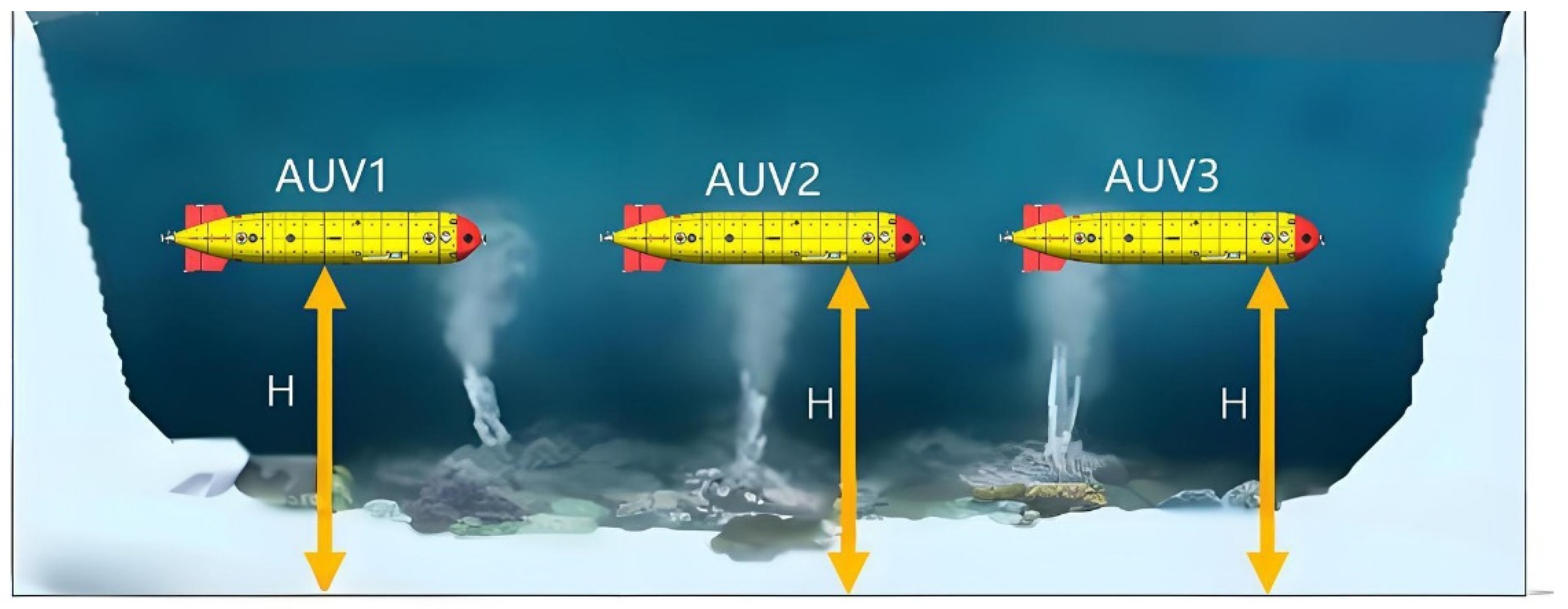
The assumed operation scenario carried out in this study is shown in Figure 3. The AUVs in the formation all move in the fixed-depth layer, so the coordination of AUVs in the depth direction is not considered.
The multi-AUV system can de designed as follows:
x ˙ i t = v i t v ˙ i t = u i t ,
where i = 1 , 2 , N , x i t n , and v i t n refer to the position and velocity vectors of the i th AUV, respectively, and u i t n refers to the control inputs.
Define θ i t = x i t , v i t T , B 1 = 1 , 0 T , and B 2 = 0 , 1 T . Then, the multi-AUV system in Equation (12) can be rewritten as follows:
θ ˙ i t = B 1 B 2 T θ i t + B 2 u i t ,
Let m i t = m i x t , m i v t T be piecewise continuously differentiable vectors i = 1 , 2 , N and m t = m 1 T t , m 2 T t , m N T t T 2 N .
Condition 1: A vector m t specifies the time-varying formation. If the multi-AUV in Equation (13) establishes time-varying formation m t for the appropriate initial states, then a vector-valued function c t 2 satisfies lim t θ i t m i t c t = 0 , where c t means the formation center function.
To certify the Condition 1, suppose we have an affine pentagon structure of a multi-AUV system with five AUVs moving in the plane. Let x i X t , m i X t , and c x X t , and x i Y t m i Y t , c x Y t refer to the position, the formation, and the formation center function of the i th AUV along the x- and y-axes in the X–Y plane, respectively.
θ i x t = x i X t , x i Y t T θ i x t = x i X t , x i Y t T c i x t = c i X t , c i Y t T ,
If θ i x t m i x t c x t 0 as t for all AUVs i 5 in Figure 4, the two pentagons indicated by m i x t and θ i x t i 5 are congruent.
Condition 2: If a vector function s t 2 makes lim t θ i t s t = 0 i = 1 , 2 , , N , then the multi-AUV system in Equation (12) can attain consensus for any bounded initial states, so a consensus function is described as s t .
From conditions 1 and 2, if m t 0 , the multi-AUV system in Equation (13) establishes the formation, and then the consensus also can be established. Thus, the time-varying formation center function and the consensus function are critical.
The time-varying formation protocol can be defined as follows:
u i t = K 1 θ i t m i t + K 2 j N i w i j θ j t m j t θ i t m i t + m ˙ i v t
where i = 1 , 2 , N , K 1 = k 11 , k 12 , and K 2 = k 21 , k 22 .
K 1 is the motion mode of the formation center, and K 2 is the appropriate value that can lead all AUVs to establish the desired formation.
Define the following:
θ t = θ 1 T t , θ 2 T t , θ N T t T m x t = m 1 x T t , m 2 x T t , m N x T t T m v t = m 1 v T t , m 2 v T t , m N v T t T ,
So, multi-AUV system (12) can be written in a compact form as Equation (15).
θ ˙ t = I N B 2 K 1 + B 1 B 2 T L B 2 K 2 θ t I N B 2 K 1 L B 2 K 2 m t + I N B 2 m ˙ t
This paper focuses on two problems for multi-AUV system in Equation (17):
  • When the time-varying formation is established.
  • If the system obtains the time-varying formation, what is the protocol in Equation (17)?

3. Theoretical Analysis

In this section, the time-varying formation for the multi-AUV system problem in Equation (14) becomes a consensus problem. Then, the necessary and sufficient conditions to establish the time-varying formation m t are proved, and the explicit formula of the time-varying formation center function is obtained. Then, a procedure is proposed to establish the gain matrices in Equation (17).

3.1. Formation Analysis

Define λ i i = 1 , 2 , N as the eigenvalues of L corresponding to G , where λ 1 = 0 with the associated eigenvector u ¯ 1 = 1 N and 0 < Re λ 2 Re λ N .
Define the following:
U 1 L U = J ,
where U = u ¯ 1 , u ¯ 2 u ¯ N , U 1 = u ˜ 1 , u ˜ 2 u ˜ N H , and the J is the form of Jordan canonical of L , u ¯ i N , and u ˜ i N i = 1 , 2 , N .
Let
θ ˜ i t = θ i t m i t i = 1 , 2 , N ,
θ ˜ t = θ ˜ 1 T t , θ ˜ 2 T t , θ ˜ N T t T ,
So, the multi-AUV system in Equation (17) can be transformed into the following:
θ ˜ ˙ t = I N B 2 K 1 + B 1 B 2 T L B 2 K 2 θ ˜ t + I N B 1 B 2 T m t + I N B 2 m ˙ v t m ˙ t ,
As B 1 = 1 , 0 T , B 2 = 0 , 1 T , and ˙ m ˙ t = I N I 2 m ˙ t , the multi-AUV system in Equation (21) can be rewritten as follows:
θ ˜ ˙ t = I N B 2 K 1 + B 1 B 2 T L B 2 K 2 θ ˜ t + I N B 1 m v t m ˙ x t ,
The following lemma holds directly.
Lemma 2. 
The multi-AUV system in Equation (17) establishes time-varying formation m(t) if and only if Equation (22) establishes consensus.
Let c 1 2 and c 2 2 be linearly independent vectors.
p j = u ¯ i c q j = 2 i 1 + q ; i = 1 , 2 , N ; q = 1 , 2 ,
A consensus subspace (CS) can be defined as the subspace U spanned by p 1 = u ¯ 1 c 1 = 1 N c 1 and p 2 = u ¯ 1 c 2 = 1 N c 2 . Moreover, a complement of the CS can be represented as the subspace ¯ U spanned by p 3 , p 4 , , p 2 N . Since p j j = 1 , 2 , , 2 N is linearly independent, the following lemma can be obtained.
Lemma 3. 
U ¯ U = 2 N .
By Lemma 1, one obtains J = diag 0 , J ¯ , where J ¯ consists of Jordan blocks corresponding to λ i i = 2 , 3 , , N .
Let
U ˜ = u ˜ 2 , u ˜ 3 , u ˜ N H ξ t = u ˜ 1 H I 2 θ ˜ t ς t = U ˜ I 2 θ t ,
The multi-AUV system in Equation (22) thus becomes the following:
ξ ˙ t = B 2 K 1 + B 1 B 2 T ξ t + u ˜ 1 H B 1 m v t m ˙ x t ,
ς ˙ t = I N 1 B 2 K 1 + B 1 B 2 T J ¯ B 2 K 2 ς t + U ˜ B 1 m v t m ˙ x t
Lemma 4. 
Based on [43]  φ ˙ t = Y φ t , we know that  Y  is a 2 × 2 complex matrix with the characteristic polynomial  f q = q 2 + a 1 q + a 2 , so the system is asymptotically stable when the only condition is the following:
Re a 1 > 0 Re a 1 Re a 1 a ¯ 2 Im a 2 2 > 0 ,
We can thus prove the necessary and sufficient conditions for the multi-AUV system in Equation (17) to obtain  m t  by the following theorem.
Theorem 1. 
The multi-AUV system in Equation (17) establishes the time-varying formation  m t  if, and only if, the following conditions hold simultaneously:
(1)
lim t m i v t m j v t m ˙ i x t m ˙ j x t = 0 , i 1 , 2 , N j N i ,
(2)
if  i 1 , 2 , N  and  ψ i = k 12 k 11 Re λ i k 12 k 21 + k 11 k 22 + Re λ i 2 + Im λ i 2 k 21 k 22 , then:
k 12 + Re λ i k 22 > 0 ,
( k 12 + Re λ i k 22 ) ψ i Im λ i 2 k 21 2 > 0 ,
The proof process is as follows:
Define the following:
θ ˜ C t = U I 2 ξ H t , 0 H θ ˜ C ¯ t = U I 2 0 , ς H t H e i R N ,
where e i R N is a vector with 1 as its i th component and 0 as other components.
Note that c 1 and c 2 refer to the linearly independent vectors. α 1 t , α 2 t , and α 2 k + j t k = 1 , 2 , , N 1 ; j = 1 , 2 must exist to meet ξ t = α 1 t c 1 + α 2 t c 2 and ς t = α 3 t c 1 H + α 4 t c 2 H , , α 2 N 1 t c 1 H + α 2 N t c 2 H H .
Because ξ H t , 0 H = e 1 ξ t ,
θ ˜ C ¯ t = U I 2 e 1 ξ t   = u ¯ 1 ξ t   = α 1 t p 1 + α 2 t p 2 U ,
Because p j j = 3 , 4 , , 2 N , Equation (32) can be expressed as follows:
θ ˜ C ¯ t = i = 2 N α 2 i 1 t u ¯ i c 1 + α 2 i t u ¯ i c 2   = j = 3 2 N α j t p j ¯ U ,
ξ H t , ς H t H = U 1 I 2 θ ˜ t then θ ˜ t = θ ˜ C t + θ ˜ C ¯ t .
According to Lemmas 2 and 3, the only condition is that when lim t θ ˜ C ¯ t = 0 , the multi-AUV system in Equation (17) obtains m t , so:
lim t ς t = 0 ,
ς ˜ ˙ t = I N 1 B 2 K 1 + B 1 B 2 T J ¯ B 2 K 2 ς ˜ t ,
Now, the multi-AUV system in Equation (17) can establish formation m t because Equation (25) is under the condition from Equations (26) and (34).
So:
lim t U ˜ B 1 m v t m ˙ x t = 0 ,
Based on Equation (28), then:
lim t L B 1 m v t m ˙ x t = 0 ,
Based on Equation (16), then:
L = U J U 1 ,
Now multiplying both sides of Equation (37) with U 1 I ,
lim t J ¯ U ˜ B 1 m v t m ˙ x t = 0 ,
Note that J ¯ is nonsingular by Lemma 1.
Next, multiplying both sides of Equation (39) with J ¯ 1 I 2 results in Equation (36). It shows Equation (12) being sufficient for Equation (36).
Then, define U ˜ = [ U ^ , u ^ ] , U ^ N 1 × N 1 , where u ^ N 1 × 1 means that u ^ is the last column vector of U ˜ . Then, we rank U ˜ = N 1 and rank U ^ = N 1 .
From Equation (36), we obtain the following:
lim t [ U ^ , u ^ ] B 1 m v t m ˙ x t = 0 ,
Note that U ˜ 1 N = 0 , and then:
u ^ = U ^ 1 N 1 ,
Define the following:
m ¯ x t = m 1 x t , m 2 x t , , m N 1 x t T m ¯ v t = m 1 v t , m 2 v t , , m N 1 v t T ,
Based on Equations (40) and (41), we obtain the following:
lim t U ^ I 2 I N 1 B 1 m ¯ v t m ¯ ˙ x t 1 N 1 B 1 × m N v t m ˙ N x t = 0
Repeat the same procedure by U ^ 1 I 2 , and then for i { 1 , .   .   .   ,   N 1 } , as follows:
lim t m i v t m N v t m ˙ i x t m ˙ N x t = 0 ,
Equation (12) is held by Equation (44). Equations (12) and (36) are equivalent under Theorem 1. So, based on the structure of J ¯ , the stability of Equation (35) is equivalent to the N − 1 subsystem, as follows:
ς ¯ ˙ i t = B 2 K 1 λ i K 2 + B 1 B 2 T ς ¯ t i = 2 , 3 , , N ,
and
B 2 K 1 λ i K 2 + B 1 B 2 T = 0 1 k 11 λ i k 21   k 12 λ i k 22 + 1 0 0 1 = 0 1 k 11 λ i k 21 k 12 λ i k 22 ,
Now, the characteristic polynomial of the state matrix of the N 1 subsystem in Equation (45) can be obtained by f i s = s 2 k 12 λ i k 22 s k 11 λ i k 21 i = 2 , 3 , , N , where s is a complex variable.
Thus, Equation (34) is asymptotically stable when Equation (13) holds.
Now, according to the above, there is an achievable formation constraint from Equation (28), and the internal stability of the subsystem in Equation (24) can be ensured by Equations (29) and (30), and the formation error converges to 0.
If the multi-AUV in Equation (17) obtains m t , it means that θ ˜ i t ξ t 0 as t under Theorem 1. Thus, we can establish the formation center function through Equation (25). The explicit expression of the formation center function is shown as follows:
Lemma 5. 
Multi-AUV in Equation (17) obtains  m t  with the function c(t) of the formation center:
lim t c t c 0 t c h t = 0 ,
where
c 0 t = e B 2 K 1 + B 1 B 2 T t u ˜ 1 H I 2 θ 0 ,
c 0 t = 0 t e B 2 K 1 + B 1 B 2 T t τ u ˜ 1 H I 2 × m v τ k 12 m v τ k 11 m x τ d τ u ˜ 1 H I 2 m t
c 0 t  is consensus function and time-varying formation center function for the multi-AUV system in Equation (17) when  m t 0 . c h t  shows the effect of  m t . If  m t 0 , the multi-AUV system’s explicit formula of consensus function is  c t . According to Theorem 2, the motion modes of the formation center informing the design of  K 1  can be selected by the eigenvalues of  B 2 K 1 + B 1 B 2 T .

3.2. Protocol Design

Next, we propose a method for determining the gain matrix of the multi-AUV implementations in Equation (13) of the time-varying formations in Equation (17).
Theorem 2. 
In Theorem 1, when Equation (12) is held, let
K 2 = Re λ 2 1 B 2 T P ¯ ,
The multi-AUV in Equation (13) obtains the time-varying formation under Equation (17), where  P ¯  is the positive-definite solution to the algebraic Riccati equation:
P ¯ B 2 K 1 + B 1 B 2 T + B 2 K 1 + B 1 B 2 T T P ¯ P ¯ B 2 B 2 T P ¯ + I ,
The proof process is as follows:
Define the Lyapunov function candidate by considering the N 1 subsystems described in Equation (48):
V i t = ς ¯ i H t P ¯ ς ¯ i t i = 2 , 3 , , N ,
Taking the derivative of V i t with respect to t , then:
V ˙ i t = ς ¯ i H t ς ¯ i t + 1 2 Re λ 2 Re λ 2 1 × ς ¯ i H t P ¯ B 2 B 2 T P ¯ ς ¯ i t ,
Note that 0 < Re λ 2 Re λ N , which makes V ˙ i t ς ¯ i H t ς ¯ i t   i = 2 , 3 , , N under Equation (53).
Now, the N 1 subsystems detailed by Equation (43) are asymptotically stable according to the Lyapunov’s second method for stability. Multi-AUV in Equation (13) establishes a time-varying formation through Equation (17), with the proof shown in Theorem 1. Thus, the proof of Theorem 2 has been completed.
So, the procedure of the multi-AUV protocol in Equation (17) is confirmed. First, setting the appropriate K 1 allows us to design the motion modes of the formation center by allocating the eigenvalues of B 2 K 1 + B 1 B 2 T at the desired locations in the complex plane. As B 1 B 2 T , B 2 is controllable, K 1 is always present. At last, we design K 2 to satisfy Equation (30) by using the conclusion of Theorem 2.

4. Simulation

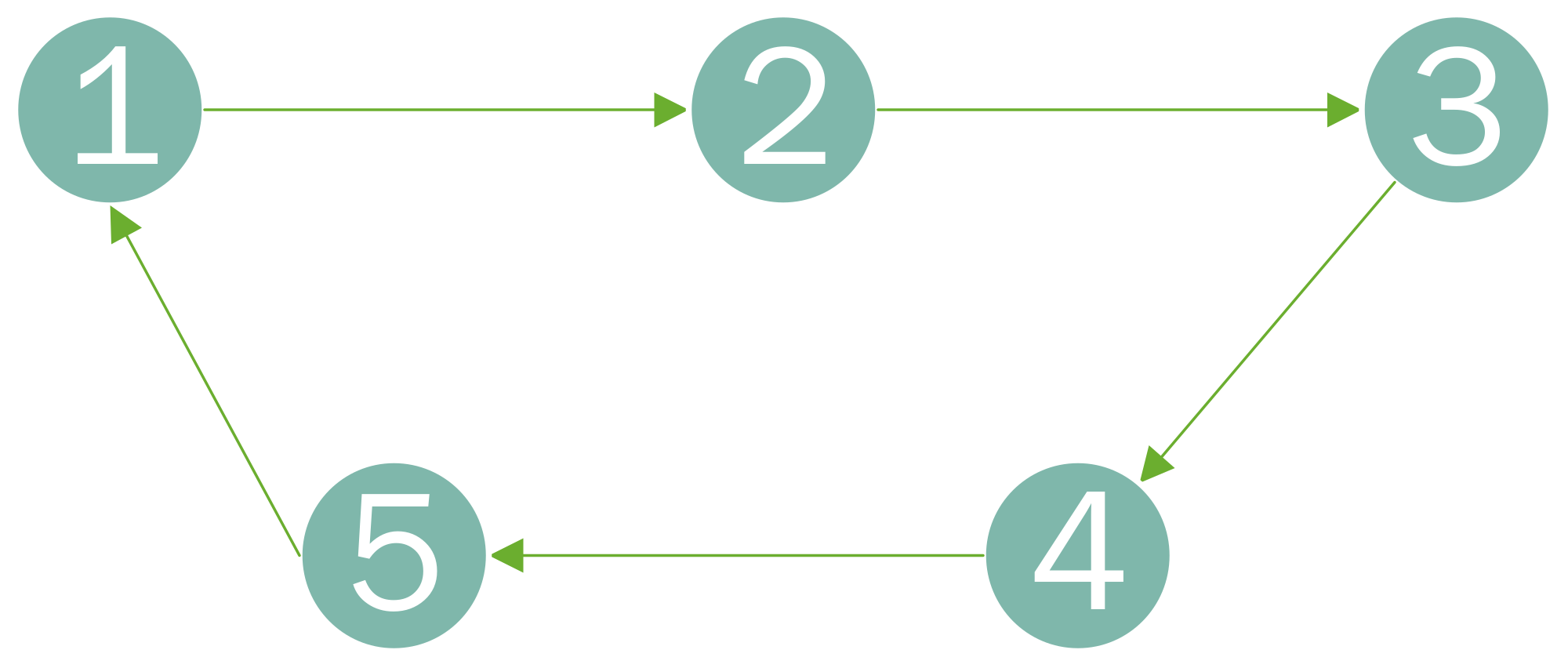
In this section, we present simulations tested on five AUVs that demonstrate the efficacy of the theoretical results. The multi-AUV’s interaction topology is shown in Figure 5, and had 0–1 weights.
Define the following:
θ i t = x i X t , v i X t , x i Y t , v i Y t T m i t = m i x X t , m i v X t , m i x Y t , m i v Y t T ,
So, the dynamics of each AUV in the case through Kronecker product with n = 2 are shown:
θ ˙ t = I N B 2 K 1 + B 1 B 2 T θ i t + I N B 1 u i t ,
Simulation 1:
Define m i t i = 2 , 3 , , N as follows:
g i t = sign ( sin ( ω t / 2 + π i 1 / 5 ) ) m i x X t = r cos ω t + 2 π i 1 / 5 1 g i t m i v X t = ω r sin ω t + 2 π i 1 / 5 1 g i t m i x Y t = r sin ω t + 2 π i 1 / 5 m i v Y t = ω r cos ω t + 2 π i 1 / 5 ,
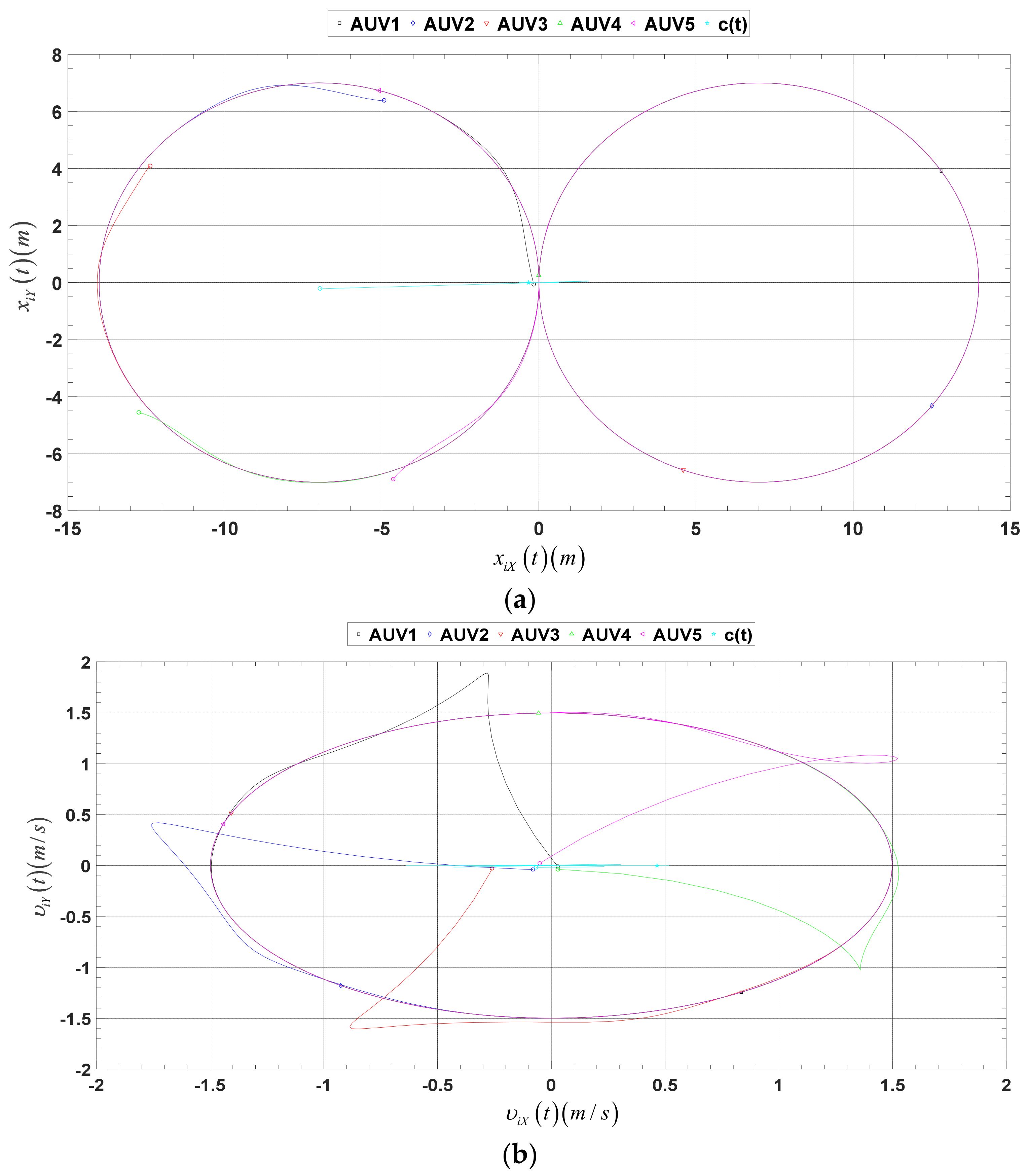
where r = 7 m and ω = 0.214 rad / s . When the multi-AUV system successfully had obtained the required time-varying formation configuration, the entire formation exhibited a highly coordinated, dynamic motion pattern. In this formation, a total of five AUVs were engaged in action, and they sailed strictly according to the preset figure-eight pattern. This mode not only required each AUV to have a high degree of autonomous navigation, but also required precise communication and coordination between them to ensure the stable operation of the entire fleet. Note that to ensure that there was no collision between the AUVs within the formation while maintaining sufficient spacing to facilitate the transmission of information and the execution of tasks, these AUVs maintained a phase separation of 0.4 T radians on the trajectory.
This design not only considered the overall stability of the formation, but also the independence and flexibility of the AUV so that the entire formation could effectively achieve various tasks in the intricate underwater environment.
The motion modes of the formation center were chosen at 0.58 + 1.26 j and 0.58 1.26 j with j 2 = 1 , K 1 = I 2 2 , 1.2 , meaning that when the multi-AUVs established the time-varying formation, the formation center was stationary.
According to the Theorem 2, we designed K 2 = I 2 0.3416 , 0.7330 . Moreover, the initial states of the five AUVs were as follows:
θ 1 0 = 0.16 , 0.03 , 0.07 , 0.03 T θ 2 0 = 4.92 , 0.08 ,   6.38 , 0.04 T θ 3 0 = 12.37 , 0.26 ,   4.08 , 0.03 T θ 4 0 = 12.73 ,   0.03 , 4.56 , 0.04 T θ 5 0 = 4.63 , 0.05 , 6.9 ,   0.02 T ,
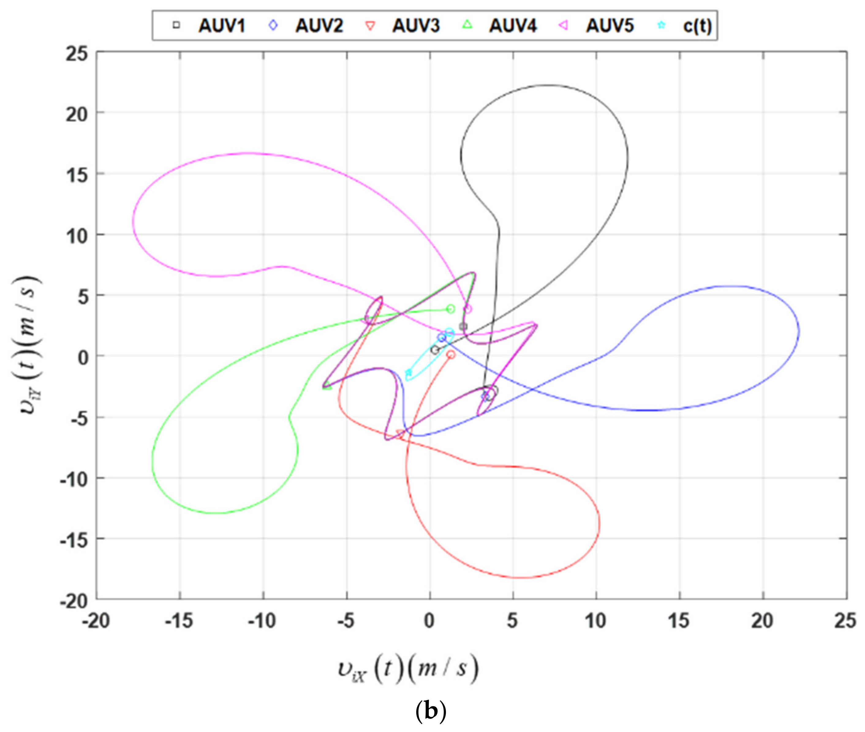
Figure 6 shows the state trajectories of the multi-AUV system in the simulation and the desired c t . In this Figure, the AUVs’ and c 0 ’s initial states are represented by circles, and the five AUVs’ and c t ’s final states are shown as the following different patterns: AUV1 is a square, AUV2 is a diamond, AUV3 is an upside-down triangle, AUV4 is a standard triangle, AUV5 is a left-pointing triangle, and c t is pentagram.
Figure 7 describes the snapshots of the c t with the 16 to 21 second positions and velocities of the five AUVs.
Choosing applicable initial states, we realized the desired time-varying formation transformation in the simulation, and the AUVs did not collide in this process.
Simulation 2:
The motion modes of the formation center function in this simulation were assigned to move periodically. Define m t as follows:
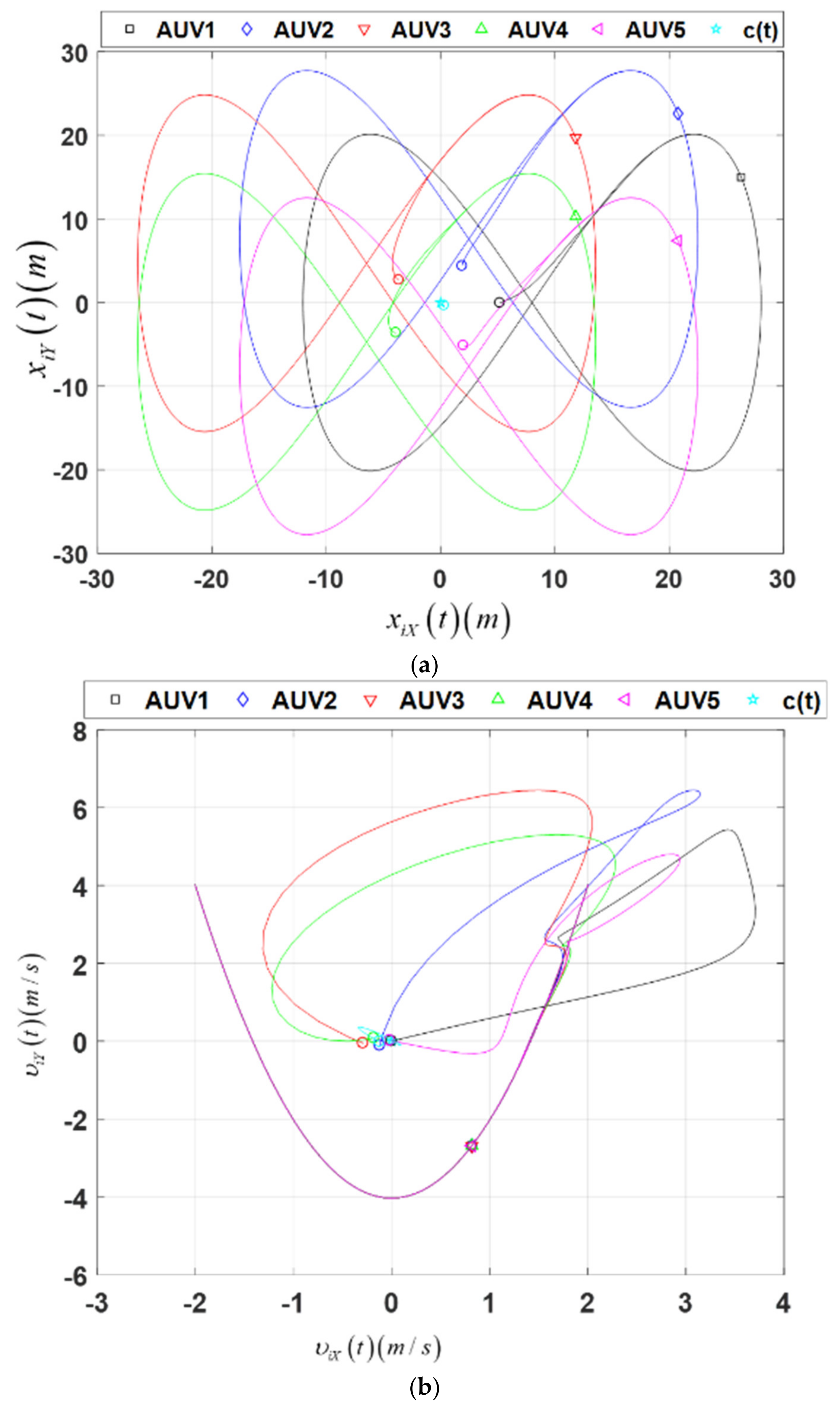
m i x X t = r sin ω t + d * cos 2 π i 1 / 5 m i v X t = ω r cos ω t m i x Y t = r sin 2 ω t + d * sin 2 π i 1 / 5 m i v Y t = 2 ω r cos ω t ,
where r = 20 m , d = 8 m , and ω = 0.1 rad / s . We chose K 1 = I 2 3 , 1.2 to assign the motion modes of the formation center at 0.5 j and 0.5 j with j 2 = 1 .
According to the Theorem 2, we defined the K 2 = I 2 1.3416 , 2.7330 .
Let the initial state of the AUV be θ i 0 = i Θ i 1 , i Θ i 2 , i Θ i 3 , i Θ i 4 T i = 1 , 2 , , 5 , where i Θ i n n = 1 , 2 , 3 , 4 is pseudorandom value with a uniform distribution on the interval 0 , 1 .
As a result, the multi-AUV system successfully obtained the required formation configuration and entered a state of collaborative work. In this mode, the center of the formation did not remain stationary, but moved periodically. As the center of the formation moved, the five AUVs moved closely around it, forming a dynamic pentagon. This mode of operation is typical for most formation situations. In practice, the formation center rarely remains stationary because such a static state is not conducive to the AUV’s mission in complex underwater environments. Therefore, periodically moving the formation center can make the whole formation more flexible, adaptable, and better able to cope with various unexpected situations and environmental changes.
Figure 8a demonstrates AUVs’ position and c t in the simulation. Figure 8b shows the velocity of the AUVs and c t in the simulation. The identification in this Figure is the same as that in Simulation 1.
Simulation 3
The formation center function’s motion modes in this simulation were assigned to move periodically, and the formation center varied randomly within a range of 10 m. We defined the time-varying formation m t   i = 2 , 3 , , N as follows:
m i x X t = r sin ω t + 2 π i 1 / 5 m i v X t = ω r cos ω t + 2 π i 1 / 5 m i x Y t = r cos 2 ω t + 2 π i 1 / 5 m i v Y t = ω r sin ω t + 2 π i 1 / 5 ,
where r = 50 m and ω = 0.1 rad / s . Let K 1 = I 2 0.25 , 0 to designate the formation center’s motion modes at 0.5 j and 0.5 j with j 2 = 1 . Define the K 2 = I 2 1.57 , 4.32 . The initial location selection was consistent with that in simulation 2.
Figure 9a demonstrates the AUVs’ position and c t in the simulation. Figure 9b shows the velocity of the AUVs and c t in the simulation. The identification in this Figure is the same as that in Simulation 1.

5. Conclusions and Discussion

This paper discusses how to realize a complex, varied time-varying formation of multi-AUVs and the formation-control strategy. In the current ocean exploration and technology application, an AUV is an efficient and autonomous underwater exploration tool, and its formation control and cooperative work ability are critical in completing complex tasks. Through theoretical analysis and algorithm design, we provided a feasible solution for multi-AUVs to establish the desired time-varying formation.
Consensus-based time-varying formation problems for multi-AUVs systems are investigated and simulation of the formation theories to multi-AUVs are presented. On the formation control level, based on the dynamic characteristics of the AUV, a consensus-based formation protocol for multi-AUV systems to achieve time-varying formations is proposed. Then, formation problems are transformed into consensus problems. Necessary and sufficient conditions for multi-AUV systems to achieve time-varying formation are presented, and an explicit expression of the time-varying formation center function is given. The formations can be any time-varying vectors satisfying condition (12). Different from most cases of collaboration, the velocities of the multi-AUVs studied in this paper are not equal when they reach the cooperative state, and the research content is more general. In addition, the interaction topology of each AUV only needs to have a spanning tree, without the information mentioned previously. Furthermore, a procedure to design the protocol for multi-AUV systems to achieve time-varying formations is proposed. The method was then verified by three typical simulations. These results not only enrich the theoretical system of formation control, but also provide an important theoretical basis for practical application.
However, owing to the complexity and variability of the marine environment, the limitation of sensor accuracy, and the unreliability of underwater communication, it is often difficult to establish the expected effect with the traditional formation-control algorithm.
Therefore, how to determine the practicability of AUV formation has become the focus of research.
Future research needs to pay more attention to practical application scenarios and to develop robust formation-control algorithms that can adapt to complex marine environments. In this way, we can ensure that AUVs can perform tasks stably and reliably under various harsh conditions.
In addition, the research content of this study was aimed at isomorphic AUVs, but the formation algorithm of heterogeneous AUVs is more valuable to study. For practicality, the heterogeneous AUV formation structure can make the formation system have stronger flexibility and adaptability to complete more complex tasks.

Author Contributions

Conceptualization, L.W.; methodology, G.S.; software, G.S.; validation, G.S. and H.X.; writing—original draft preparation, G.S.; writing—review and editing, H.X.; visualization, G.S.; supervision, H.X.; project administration, H.X.; funding acquisition, H.X. All authors have read and agreed to the published version of the manuscript.

Funding

This work was supported by the National Key R&D Program of China [grant no. 2021YFC2800100] and the Natural Science Foundation of Liaoning Province, China, [grant no. 2022-MS-035].

Institutional Review Board Statement

Not applicable.

Informed Consent Statement

Not applicable.

Data Availability Statement

The original contributions presented in the study are included in the article, further inquiries can be directed to the corresponding author.

Acknowledgments

The research was performed at Harbin Engineering University and Shenyang Institute of Automation (SIA), as well as the Chinese Academy of Sciences.

Conflicts of Interest

The authors declare no conflicts of interest.

References

  1. Weitz, L.A.; Hurtado, J.E.; Sinclair, A.J. Decentralized cooperative-control design for multivehicle formations. J. Guid. Control Dyn. 2008, 31, 970–979. [Google Scholar] [CrossRef]
  2. Yang, S.; Chen, J.; Liu, F. Observer-based consensus control of multi-agent systems with input delay. In Proceedings of the 2018 IEEE 4th International Conference on Control Science and Systems Engineering (ICCSSE), Wuhan, China, 21–23 August 2018; IEEE: Piscataway, NJ, USA, 2018; pp. 533–537. [Google Scholar]
  3. Cai, W.; Liu, Z.; Zhang, M.; Lv, S.; Wang, C. Cooperative formation control for multiple AUVs with intermittent underwater acoustic communication in IoUT. IEEE Internet Things J. 2023, 10, 15301–15313. [Google Scholar] [CrossRef]
  4. Li, J.; Zhang, H.; Chen, T.; Wang, J. AUV formation coordination control based on transformed topology under time-varying delay and communication interruption. J. Mar. Sci. Eng. 2022, 10, 950. [Google Scholar] [CrossRef]
  5. Okamoto, A.; Kim, K.; Sasano, M.; Sato, T.; Inaba, S.; Kondo, S.; Matsumoto, H.; Murashima, T.; Shimura, T.; Fujiwara, T.; et al. Development of a basic formation control system for heterogeneous autonomous marine vehicles and its sea trials in suruga bay. In Proceedings of the 2023 IEEE Underwater Technology (UT), Tokyo, Japan, 6–9 March 2023; IEEE: Piscataway, NJ, USA, 2023; pp. 1–10. [Google Scholar]
  6. Yan, Z.; Pan, X.; Yang, Z.; Yue, L. Formation control of leader-following multi-uuvs with uncertain factors and time-varying delays. IEEE Access 2019, 7, 118792–118805. [Google Scholar] [CrossRef]
  7. Yan, Z.; Yang, Z.; Pan, X.; Zhou, J.; Wu, D. Virtual leader based path tracking control for multi-uuv considering sampled-data delays and packet losses. Ocean Eng. 2020, 216, 108065. [Google Scholar] [CrossRef]
  8. Suryendu, C.; Subudhi, B. Formation control of multiple autonomous underwater vehicles under communication delays. IEEE Trans. Circuits Syst. II Express Briefs 2020, 67, 3182–3186. [Google Scholar] [CrossRef]
  9. Li, J.; Tian, Z.; Zhang, H. Discrete-time AUV formation control with leader-following consensus under time-varying delays. Ocean Eng. 2023, 286, 115678. [Google Scholar] [CrossRef]
  10. Zhang, N.; Niu, W.; Li, T. Consistency control of multi—Agent system based on unknown input observer. IFAC-PapersOnLine 2018, 51, 566–571. [Google Scholar] [CrossRef]
  11. Shao, G.; Wan, L.; Xu, H. Multi-AUV control method based on inverse optimal control of integrated obstacle avoidance algorithm. Appl. Sci. 2023, 13, 12198. [Google Scholar] [CrossRef]
  12. Zhang, M.; Yan, Z.; Zhou, J.; Yue, L. Distributed dual closed-loop model predictive formation control for collision-free multi-AUV system subject to compound disturbances. J. Mar. Sci. Eng. 2023, 11, 1897. [Google Scholar] [CrossRef]
  13. Xu, B.; Wang, Z.; Li, W.; Yu, Q. Distributed robust model predictive control-based formation-containment tracking control for autonomous underwater vehicles. Ocean Eng. 2023, 283, 115210. [Google Scholar] [CrossRef]
  14. Arcos-Legarda, J.; Gutiérrez, Á. Robust model predictive control based on active disturbance rejection control for a robotic autonomous underwater vehicle. J. Mar. Sci. Eng. 2023, 11, 929. [Google Scholar] [CrossRef]
  15. Pang, W.; Zhu, D.; Chu, Z.; Chen, Q. Distributed adaptive formation reconfiguration control for multiple AUVs based on affine transformation in three-dimensional ocean environments. IEEE Trans. Veh. Technol. 2023, 72, 7338–7350. [Google Scholar] [CrossRef]
  16. Zhang, P.; de Queiroz, M.; Cai, X. Three-dimensional dynamic formation control of multi-agent systems using rigid graphs. J. Dyn. Syst. Meas. Contr. 2015, 137, 111006. [Google Scholar] [CrossRef]
  17. Cai, X.; Queiroz, M.d. Adaptive rigidity-based formation control for multirobotic vehicles with dynamics. IEEE Trans. Control Syst. Technol. 2015, 23, 389–396. [Google Scholar] [CrossRef]
  18. Oh, K.-K.; Ahn, H.-S. Distance-based undirected formations of single-integrator and double-integrator modeled agents in n-dimensional space. Int. J. Robust Nonlinear Control 2013, 24, 1809–1820. [Google Scholar] [CrossRef]
  19. Ramazani, S.; Selmic, R.; de Queiroz, M. Rigidity-based multiagent layered formation control. IEEE Trans. Cybern. 2017, 47, 1902–1913. [Google Scholar] [CrossRef]
  20. Yan, Z.; Yue, L.; Zhou, J.; Pan, X.; Zhang, C. Formation coordination control of leaderless multi-AUV system with double independent communication topology and nonconvex control input constraints. J. Mar. Sci. Eng. 2023, 11, 107. [Google Scholar] [CrossRef]
  21. Yu, W.; DiMassa, D.D. Formation control of networked autonomous underwater vehicles with obstacle avoidance. In Proceedings of the OCEANS 2022, Hampton Roads, VA, USA, 17–20 October 2022; IEEE: Piscataway, NJ, USA, 2022; pp. 1–7. [Google Scholar]
  22. Gao, Z.; Guo, G. Fixed-time leader-follower formation control of autonomous underwater vehicles with event-triggered intermittent communications. IEEE Access 2018, 6, 27902–27911. [Google Scholar] [CrossRef]
  23. Xia, G.; Zhang, Y.; Zhang, W.; Chen, X.; Yang, H. Dual closed-loop robust adaptive fast integral terminal sliding mode formation finite-time control for multi-underactuated AUV system in three dimensional space. Ocean Eng. 2021, 233, 108903. [Google Scholar] [CrossRef]
  24. Yan, Z.; Zhang, C.; Zhang, K.; Cai, S. Research on guaranteed cost formation tracking control of multi-auv with virtual leader. In Proceedings of the OCEANS 2023—Limerick, Limerick, Ireland, 5–8 June 2023; IEEE: Piscataway, NJ, USA, 2023; pp. 1–6. [Google Scholar]
  25. Li, J.; Tian, Z.; Zhang, G.; Li, W. Multi-AUV formation predictive control based on CNN-LSTM under communication constraints. J. Mar. Sci. Eng. 2023, 11, 873. [Google Scholar] [CrossRef]
  26. Li, J.; Tian, Z.; Zhang, H.; Li, W. Robust finite-time control of a multi-AUV formation based on prescribed performance. J. Mar. Sci. Eng. 2023, 11, 897. [Google Scholar] [CrossRef]
  27. Zuo, Z. Non-singular fixed-time terminal sliding mode control of non-linear systems. IET Control Theory Appl. 2015, 9, 545–552. [Google Scholar] [CrossRef]
  28. Zuo, Z. Nonsingular fixed-time consensus tracking for second-order multi-agent networks. Automatica 2015, 54, 305–309. [Google Scholar] [CrossRef]
  29. Ni, J.; Liu, L.; Liu, C.; Hu, X.; Li, S. Fast fixed-time nonsingular terminal sliding mode control and its application to chaos suppression in power system. IEEE Trans. Circuits Syst. II Express Briefs 2017, 64, 151–155. [Google Scholar] [CrossRef]
  30. Ni, J.; Liu, L.; Liu, C.; Liu, J. Fixed-time leader-following consensus for second-order multiagent systems with input delay. IEEE Trans. Ind. Electron. 2017, 64, 8635–8646. [Google Scholar] [CrossRef]
  31. Li, X.; Zhang, Y.; Bao, H.; Zhap, G. Nonsingular terminal sliding mode based impact angle constraint guidance law with fixed-time convergence. Control Decis. 2020, 35, 474–482. [Google Scholar] [CrossRef]
  32. Wang, C.; Wen, G.; Peng, Z.; Zhang, X. Integral sliding-mode fixed-time consensus tracking for second-order non-linear and time delay multi-agent systems. J. Frankl. Inst. 2019, 356, 3692–3710. [Google Scholar] [CrossRef]
  33. Jenabzadeh, A.; Safarinejadian, B. Distributed estimation and control for nonlinear multi-agent systems in the presence of input delay or external disturbances. ISA Trans. 2020, 98, 198–206. [Google Scholar] [CrossRef]
  34. Wang, C.; Tnunay, H.; Zuo, Z.; Lennox, B.; Ding, Z. Fixed-time formation control of multirobot systems: Design and experiments. IEEE Trans. Ind. Electron. 2019, 66, 6292–6301. [Google Scholar] [CrossRef]
  35. Mehra, S.; Sahoo, S.R. Trajectory tracking with input delay in multi-agent system: Double integrator case. In Proceedings of the 2016 International Conference on Unmanned Aircraft Systems (ICUAS), Arlington, VA, USA, 7–10 June 2016; IEEE: Piscataway, NJ, USA, 2016; pp. 387–393. [Google Scholar]
  36. Wu, C.; Karimi, H.R.; Shan, L.; Dai, Y. Data-driven iterative learning cooperative trajectory tracking control for multiple autonomous underwater vehicles with input saturation constraints. J. Field Robot. 2024. Early View. [Google Scholar] [CrossRef]
  37. Fay, K.; Giordano, M.; Soto, A.; Clark, C.M.; Spurgeon, E.; Anderson, J.; Lowe, C. Multi-Robot Expansive Planning and Trajectory Evaluation for Tracking and Localization of Marine Life. In Proceedings of the 38th ACM/SIGAPP Symposium on Applied Computing, Tallinn, Estonia, 27–31 March 2023. [Google Scholar] [CrossRef]
  38. Lins De Oliveira, É.; Maia Matarazzo Orsino, R.; Crisol Donha, D. Formation-Kee and Cooperative Control of AUVs Based on the Udwadia-Kalaba Equation. In Proceedings of the International Design Engineering Technical Conferences and Computers and Information in Engineering Conference, Boston, MA, USA, 20–23 August 2023; American Society of Mechanical Engineers: New York, NY, USA, 2023; Volume 87387. [Google Scholar] [CrossRef]
  39. Chen, B.; Hu, J.; Ghosh, B.K. Finite-time tracking control of heterogeneous multi-AUV systems with partial measurements and intermittent communication. Sci. China Inf. Sci. 2024, 67, 152202. [Google Scholar] [CrossRef]
  40. Mokhtari, M.; Taghizadeh, M.; Mazare, M. Distributed Consensus and Formation Control of Multi-AUV Systems under Actuator Faults and Switching Topology. Eur. J. Control. 2024, 79, 101006. [Google Scholar] [CrossRef]
  41. Godsil, C.; Royle, G. Algebraic Graph Theory; Springer: New York, NY, USA, 2001. [Google Scholar] [CrossRef]
  42. Wei, R.; Beard, R.W. Consensus seeking in multiagent systems under dynamically changing interaction topologies. IEEE Trans. Autom. Control 2005, 50, 655–661. [Google Scholar] [CrossRef]
  43. Zahreddine, Z.; El-Shehawey, E.F. On the stability of a system of differential equations with complex coefficients. Indian J. Pure Appl. Math. 1988, 19, 963–972. [Google Scholar]
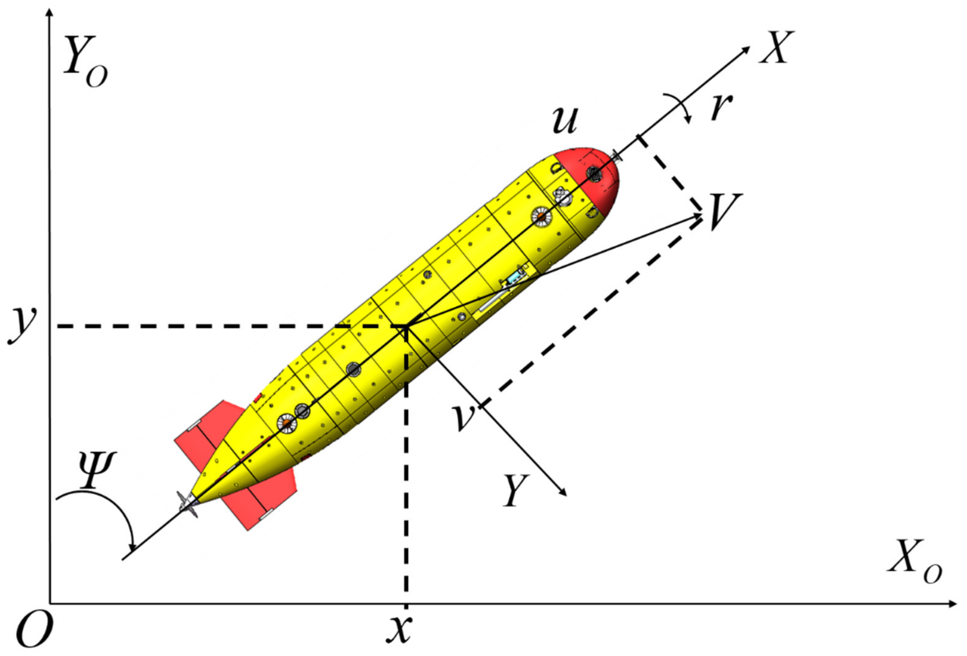
Figure 1. The autonomous underwater vehicle (AUV) coordinate diagram.
Applsci 14 06377 g001
Figure 2. Two-loop formation-control scheme for multiple-AUV (multi-AUV) systems.
Applsci 14 06377 g002
Figure 3. All AUVs operate at the same height (distance from the ocean floor).
Applsci 14 06377 g003
Figure 4. AUV formation on the X–Y plane with N = 5.
Applsci 14 06377 g004
Figure 5. Directed interaction topology G about the five AUVs.
Applsci 14 06377 g005
Figure 6. The trajectories of five AUVs and c t in the simulation. (a) The position trajectories of five AUVs in the simulation; (b) the velocity trajectories of five AUVs in the simulation.
Applsci 14 06377 g006
Figure 7. Position snapshots of θ t and c t for c t t 16 s , 21 s in the simulation.
Applsci 14 06377 g007
Figure 8. State trajectories of five AUVs in the simulation and c t . (a) The position trajectories of five AUVs in the simulation; (b) the velocity trajectories of five AUVs in the simulation.
Applsci 14 06377 g008
Figure 9. State trajectories of the five AUVs in the simulation and c t . (a) The position trajectories of the five AUVs in the simulation; (b) the velocity trajectories of the five AUVs in the simulation.
Applsci 14 06377 g009aApplsci 14 06377 g009b
Disclaimer/Publisher’s Note: The statements, opinions and data contained in all publications are solely those of the individual author(s) and contributor(s) and not of MDPI and/or the editor(s). MDPI and/or the editor(s) disclaim responsibility for any injury to people or property resulting from any ideas, methods, instructions or products referred to in the content.