
Unloading Technology and Application Research of Variable Diameter Drilling in Dynamic Pressure Roadway


Abstract
1. Introduction
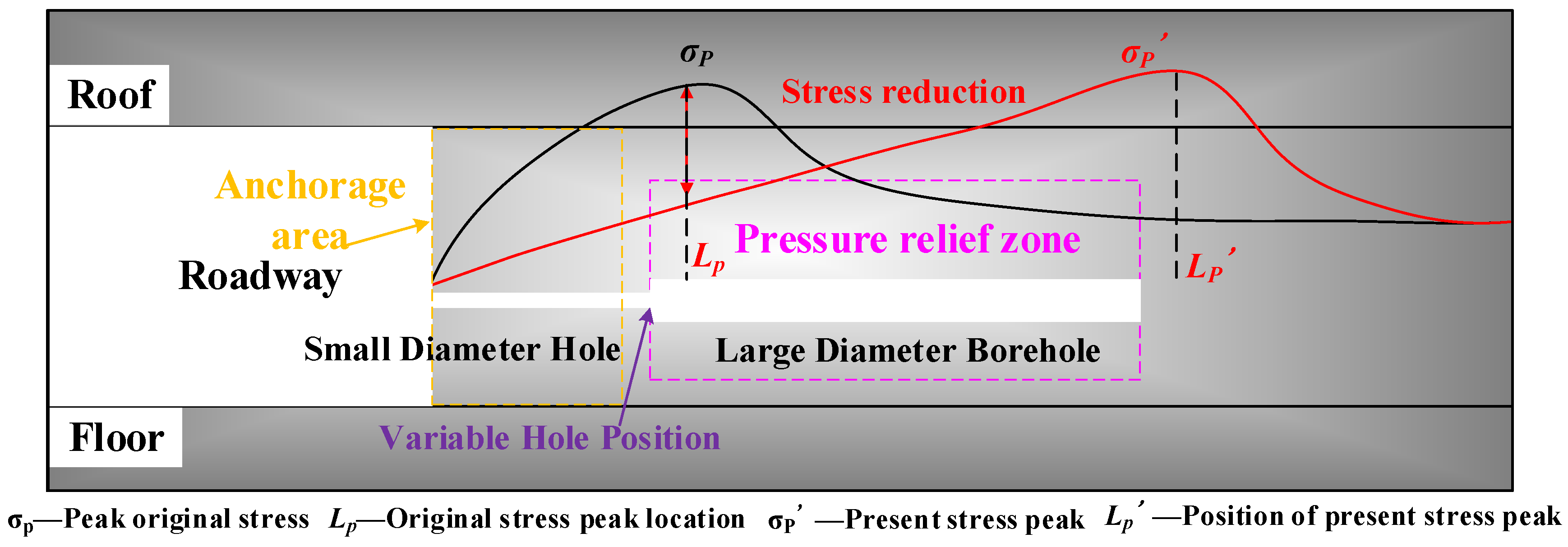
2. The Pressure Relief Principle of Variable Diameter Borehole
3. Materials and Methods
- (1)
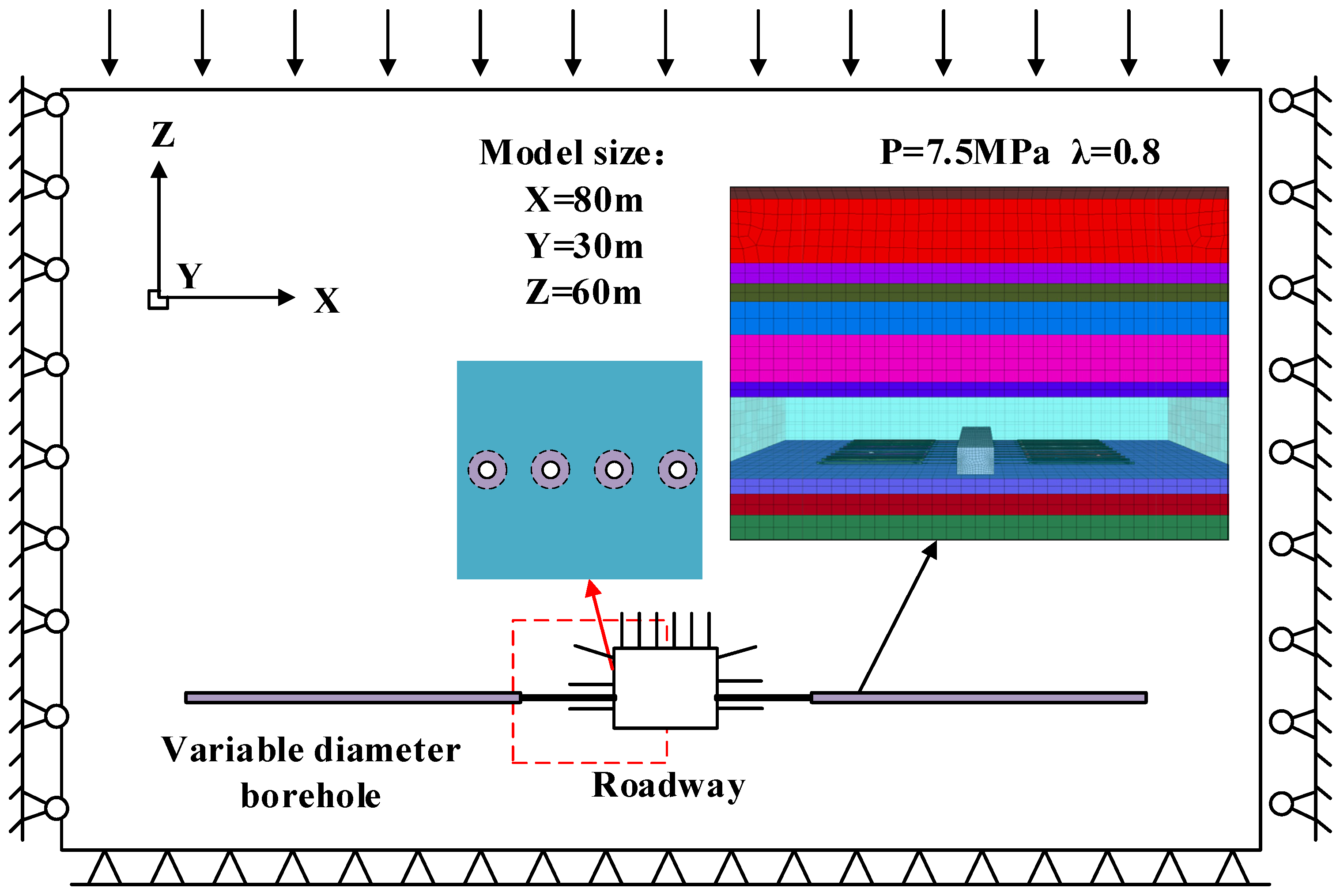
- Model parameters and boundary conditions
- (2)
- The constitutive model and mechanical parameters
4. Results and Discussion
4.1. Influence of Different Parameters on Vertical Stress Distribution in the Surrounding Rock
- (1)
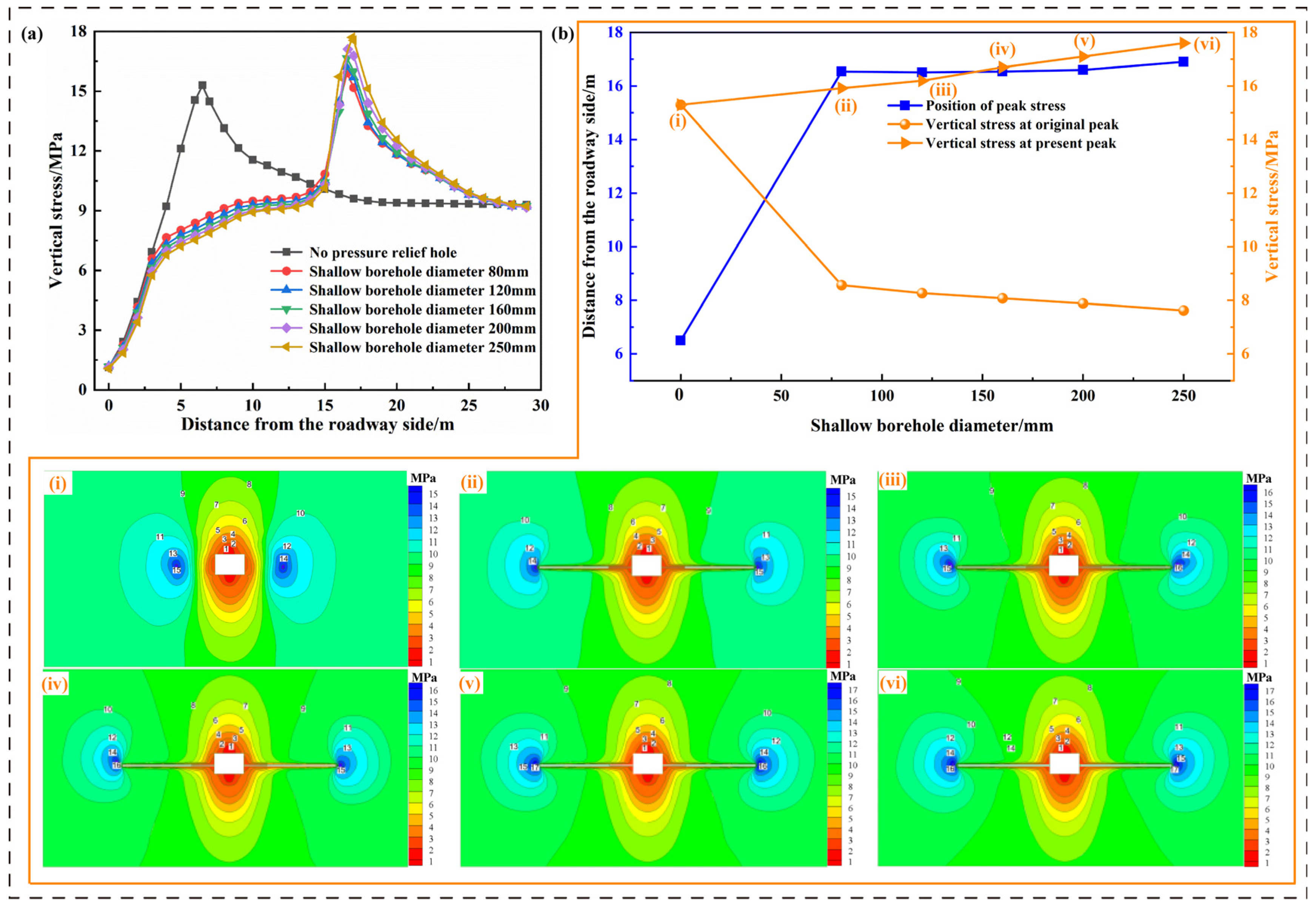
- Shallow borehole diameter
- (2)
- Deep borehole diameter
- (3)
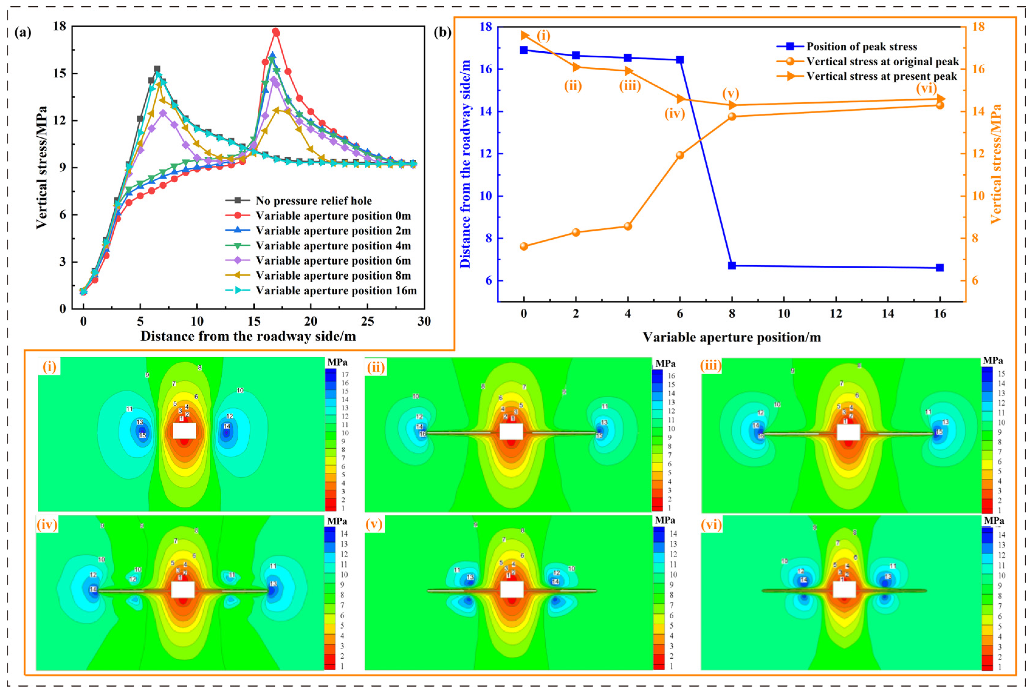
- Variable aperture position
- (4)
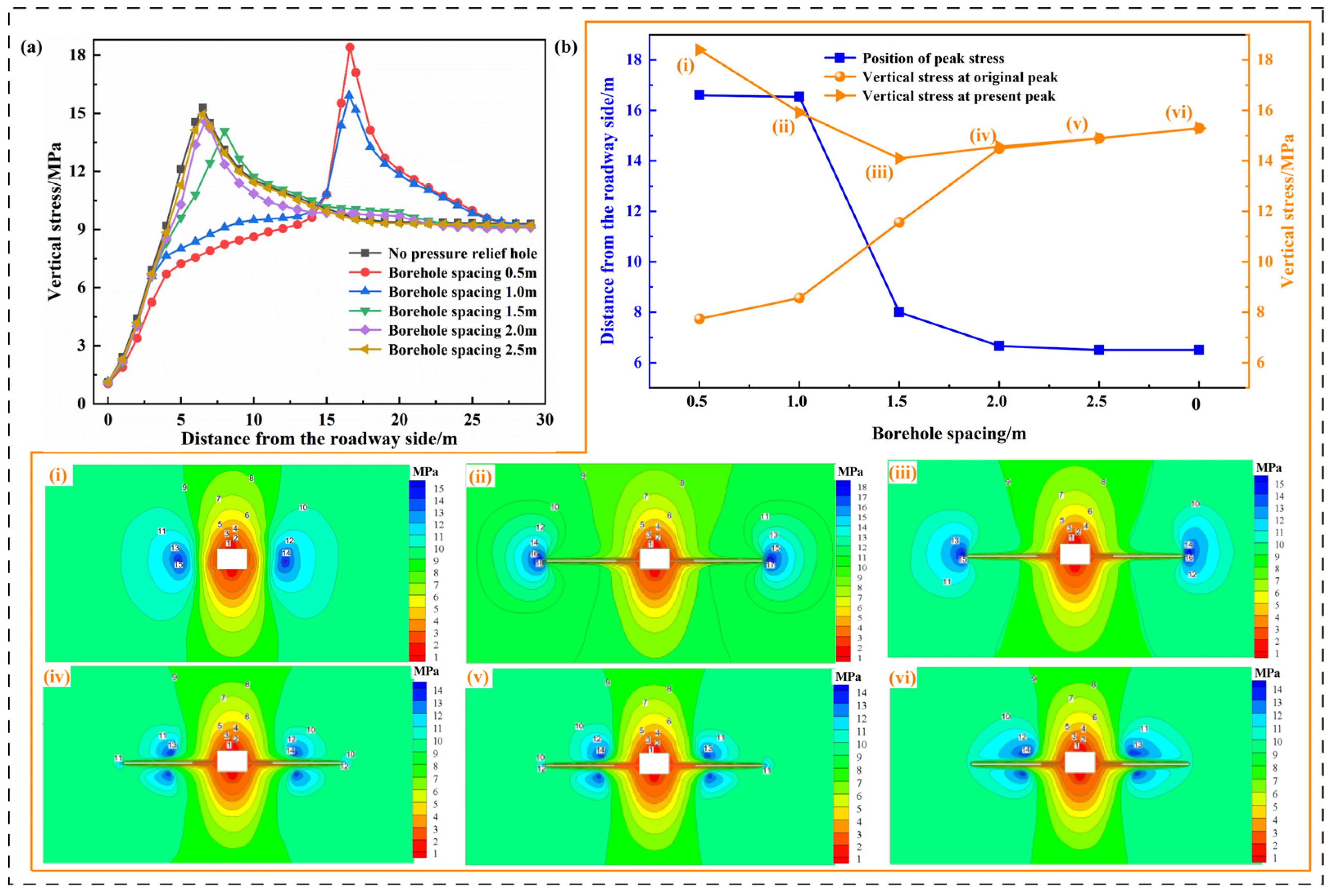
- Borehole spacing
4.2. Influence of Different Parameters on the Deformation of Surrounding Rock
- (1)
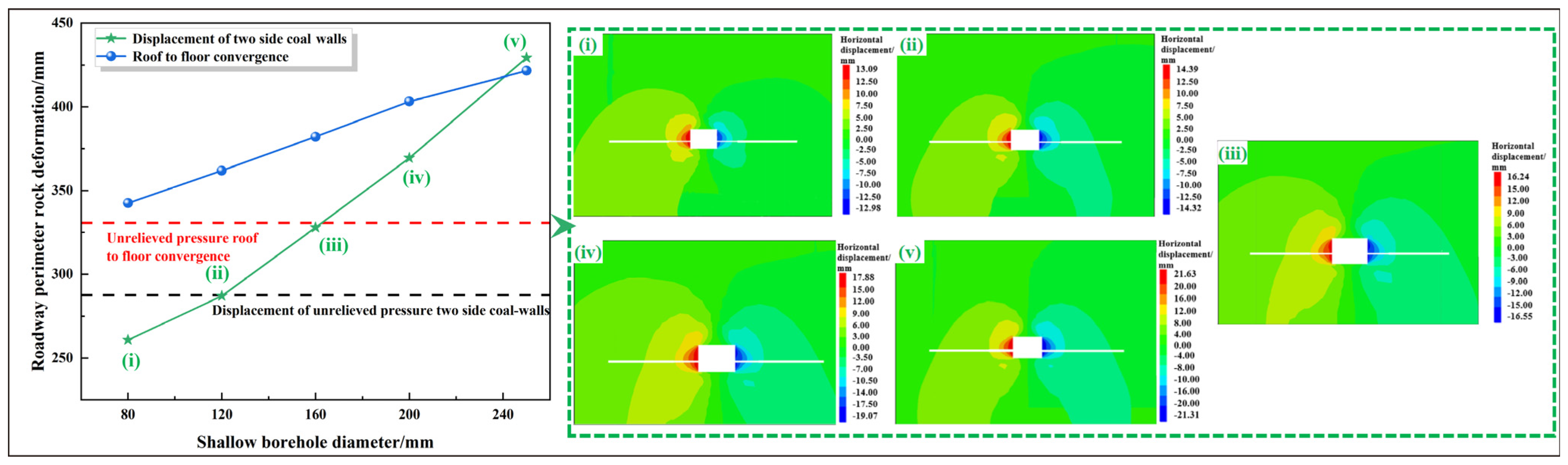
- Shallow borehole diameter
- (2)
- Deep Borehole Diameter
- (3)
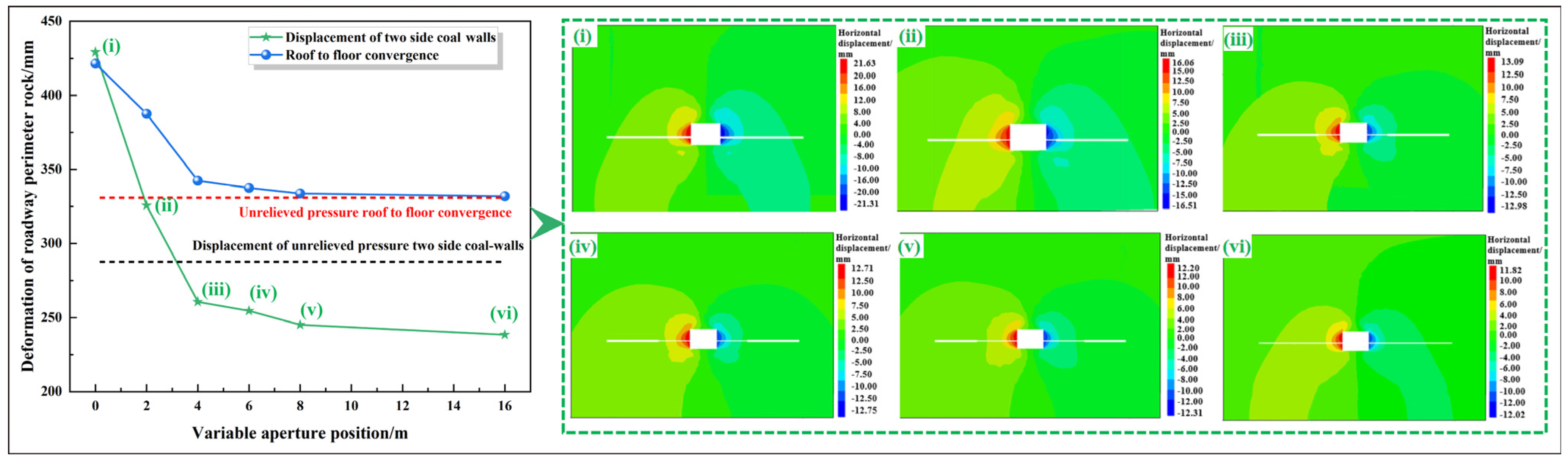
- Variable aperture position
- (4)
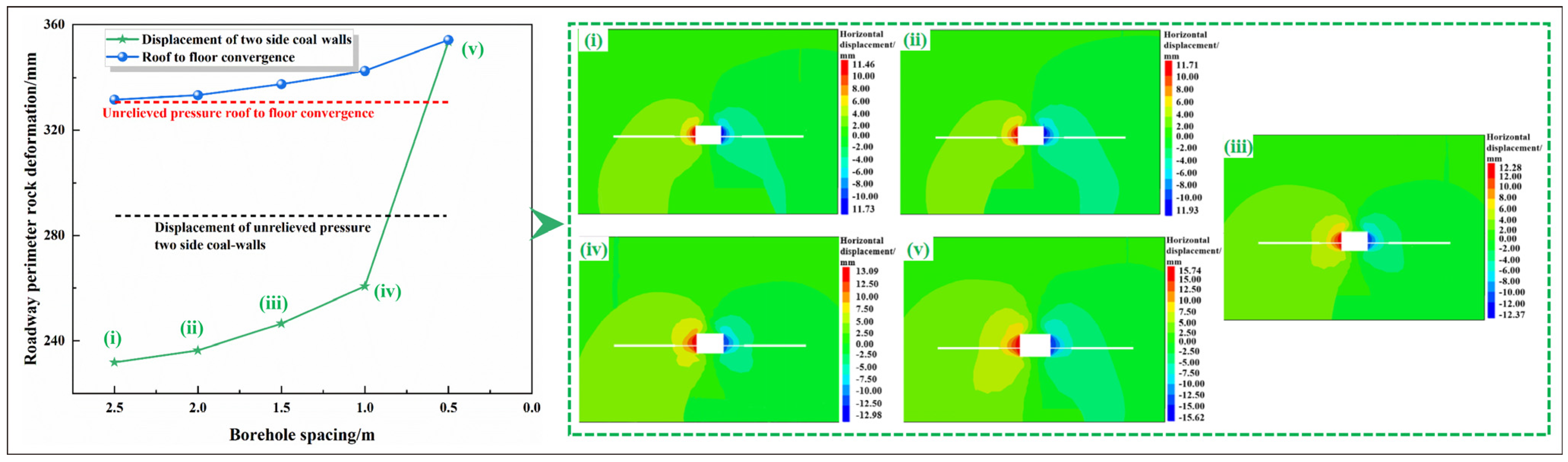
- Borehole spacing
4.3. Influence of Different Parameters on the Support Structure
- (1)
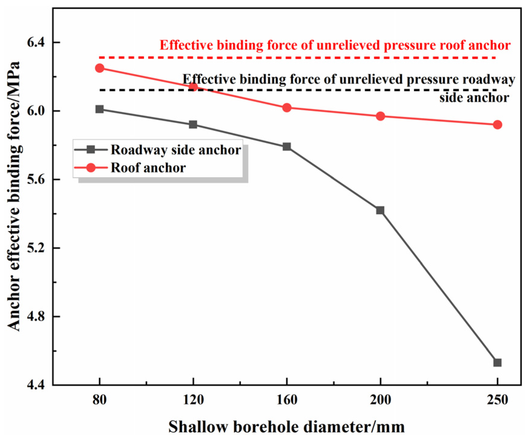
- Shallow borehole diameter
- (2)
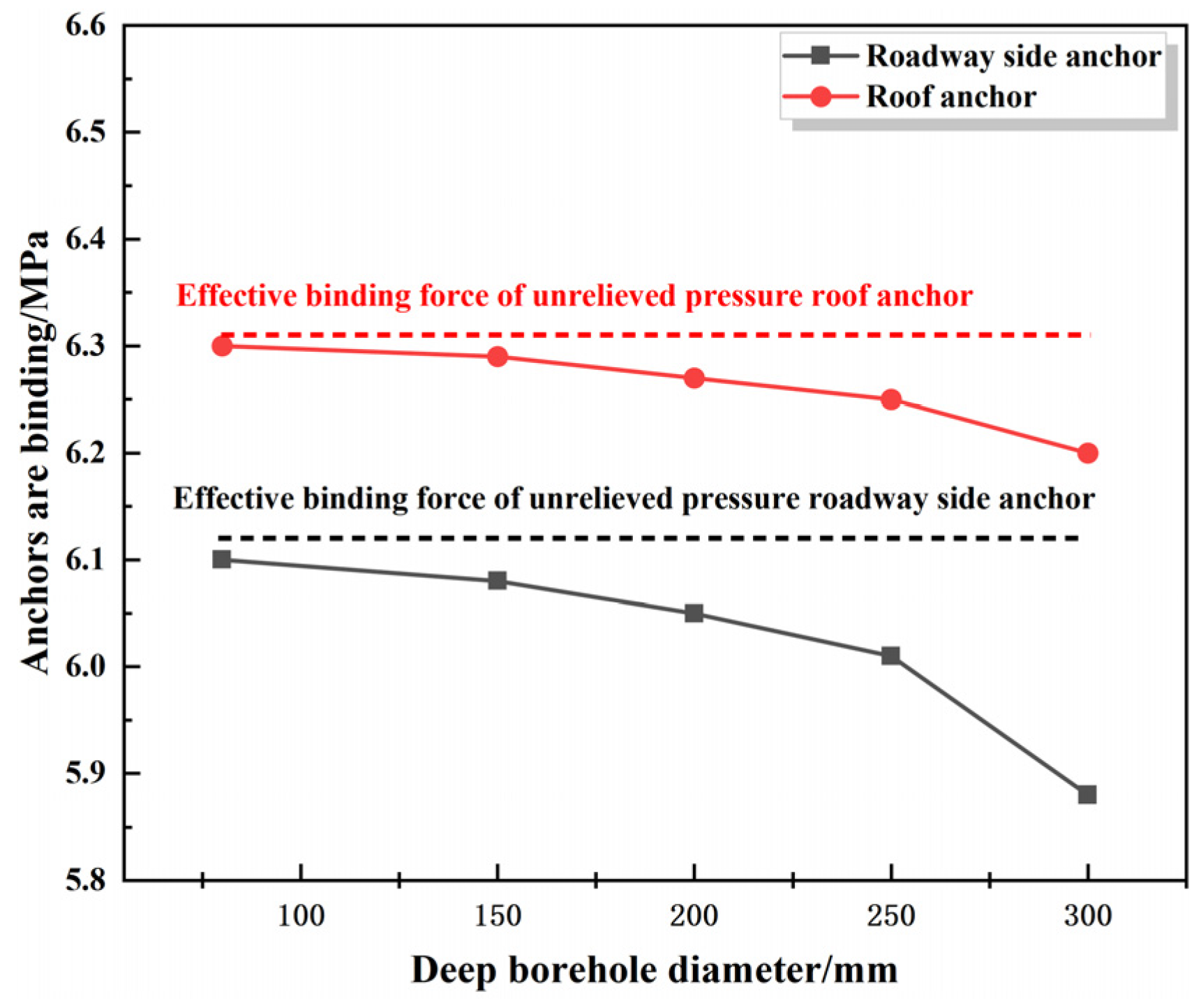
- Deep borehole diameter
- (3)
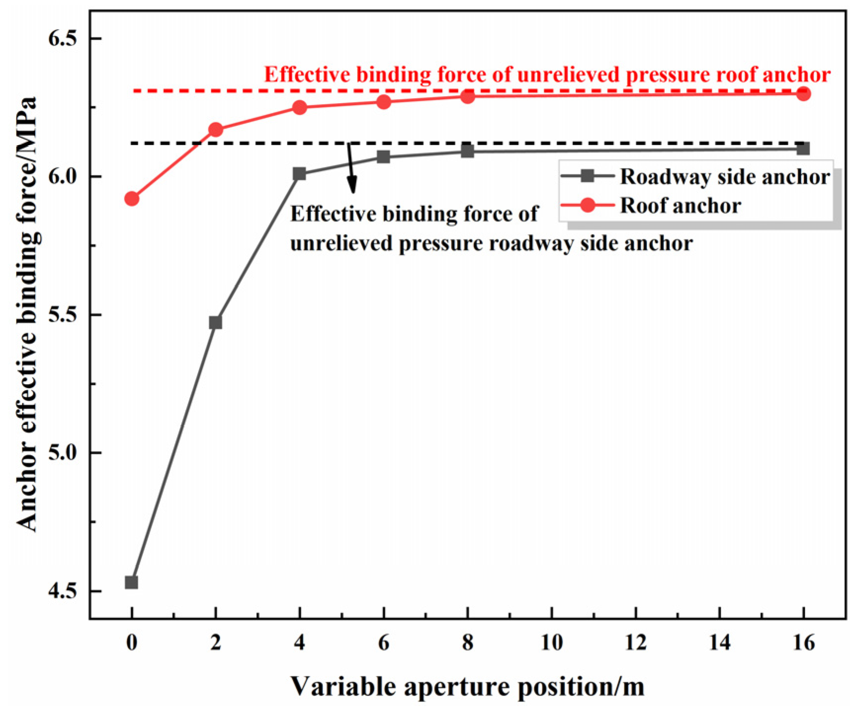
- Variable aperture position
- (4)
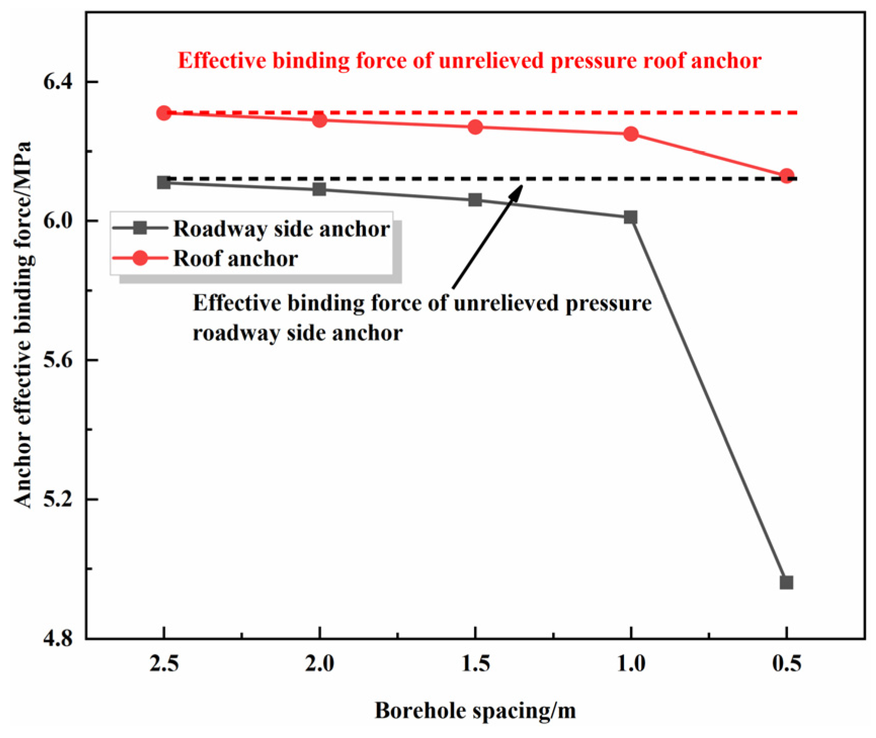
- Borehole spacing
5. Industrial Testing
5.1. The Variable Diameter Borehole Program
5.2. Monitoring by the Method of Drilling Bits
5.3. Stress On-Line Monitoring
6. Conclusions
- (1)
- Shallow borehole diameter has less influence on stress transfer and more influence on roadway deformation and support structure. When the shallow borehole diameter increases, the deformation of the roadway becomes larger, and the effective binding force of the anchor decreases, which is easy to cause the de-anchoring phenomenon.
- (2)
- The deep borehole diameter has a greater influence on stress transfer and a smaller influence on roadway deformation and support structure. The larger the deep borehole diameter, the smaller the change of surrounding rock stress and effective binding force of the anchor, but the pressure relief zone formed in the deep part of the borehole continues to increase. And the effect of roadway stress transfer is better.
- (3)
- The influence of variable borehole diameter position on stress transfer, roadway deformation, and anchor support is larger. With variable aperture position in the anchorage area, the stress transfer effect is better, but the roadway deformation is larger, and the effective binding force of the anchor is smaller. With variable aperture position between the anchorage area and the peak stress position of the roadway side, the stress transfer effect is better, and the deformation of the roadway is smaller, the effective binding force of the anchor is reduced to a lesser extent. With variable aperture position outside the peak stress position of the roadway side, although the deformation of the roadway is reduced, the effective binding force of the anchor is also small, but the stress transfer effect is better. Although the deformation of the roadway is reduced, the change of the effective binding force of the anchors is also small, but the effect of stress transfer is poor.
- (4)
- Borehole spacing has a significant effect on the stress transfer to the surrounding rock, the deformation of the roadway, and the impact of anchor support. When the borehole spacing is larger than 2.0 m, the effect of vertical stress transfer is poor. When the borehole spacing is between 1.0 m and 2.0 m, the vertical stress begins to transfer to the depth of the surrounding rock, the deformation of the roadway is small, and the effective constraint force of the anchors can be maintained at the normal level. When the borehole spacing is smaller than 1.0 m, the deformation of the roadway is larger, and the effective binding force of the anchors decreases sharply.
- (5)
- The variable diameter drilling program is given, and variable diameter boreholes are constructed within 200 m of the working face. The boreholes are arranged in a single row, 1.5 m away from the floor, with a spacing of 2.0 m. The depth of the holes on the coal wall side is 16 m, the depth of the holes on the coal pillar side is 12 m, the diameter of the shallow boreholes is 100 mm, and the diameter of the deep boreholes is 250 mm; the position of the variable diameter boreholes is located in the place of 4 m away from roadway side. The industrial test was carried out in the 19,111 auxiliary transport roadway of the Pingshuo No.1 Coal Mine. Through the method of drilling bits and the monitoring of the drilling stress gauge, the stress concentration of the surrounding rock in the roadway is reduced, which proves that the variable diameter drilling pressure relief program is reasonable and feasible.
Author Contributions
Funding
Institutional Review Board Statement
Informed Consent Statement
Data Availability Statement
Acknowledgments
Conflicts of Interest
References
- Cao, A.; Dou, L.; Bai, X.; Liu, Y.; Yang, K.; Li, J.; Wang, C. State-of-the-art occurrence mechanism and hazard control of mining tremorsand their challenges in Chinese coal mines. J. China Coal Soc. 2023, 48, 1894–1918. [Google Scholar]
- Dou, L.; Tian, X.; Cao, A.; Gong, S.; He, H.; He, J.; Cai, W.; Li, X. Present situation and problems of coal mine rock burst prevention and control in China. J. China Coal Soc. 2022, 47, 152–171. [Google Scholar]
- Zhan, Q.; Shahani, N.M.; Zheng, X.; Xue, Z.; He, Y. Instability mechanism and coupling support technology of full section strong convergence roadway with a depth of 1350 m. Eng. Fail. Anal. 2022, 139, 106374. [Google Scholar] [CrossRef]
- Xie, S.; Pan, H.; Zeng, J.; Wang, E.; Qiao, S. A case study on control technology of surrounding rock of a large section chamber under a 1200-m deep goaf in Xingdong coal mine, China. Eng. Fail. Anal. 2019, 104, 112–125. [Google Scholar] [CrossRef]
- Wang, P.; Zhang, N.; Kan, J.; Xu, X.; Cui, G. Instability mode and control technology of surrounding rock in composite roof coal roadway under multiple dynamic pressure disturbances. Geofluids 2022, 2022, 19. [Google Scholar] [CrossRef]
- Yang, H.; Zhang, N.; Han, C.; Sun, C.; Song, G.; Sun, Y.; Sun, K. Stability control of deep coal roadway under the pressure relief effect of adjacent roadway with large deformation: A case study. Sustainability 2021, 13, 4412. [Google Scholar] [CrossRef]
- Zhang, C.; Canbulat, I.; Hebblewhite, B.; Ward, C.R. Assessing coal burst phenomena in mining and insights into directions for future research. Int. J. Coal Geol. 2017, 179, 28–44. [Google Scholar] [CrossRef]
- Pu, Y.; Apel, D.B.; Prusek, S.; Walentek, A.; Cichy, T. Back-analysis for initial ground stress field at a diamond mine using machine learning approaches. Nat. Hazards 2021, 105, 191–203. [Google Scholar] [CrossRef]
- Wang, C.; Wu, A.; Lu, H.; Bao, T.; Liu, X. Predicting rockburst tendency based on fuzzy matter–element model. Int. J. Rock Mech. Min. Sci. 2015, 75, 224–232. [Google Scholar] [CrossRef]
- Frid, V. Calculation of electromagnetic radiation criterion for rockburst hazard forecast in coal mines. Pure Appl. Geophys. 2001, 158, 931–944. [Google Scholar] [CrossRef]
- Hosseini, N. Evaluation of the rockburst potential in longwall coal mining using passive seismic velocity tomography and image subtraction technique. J. Seismol. 2017, 21, 1101–1110. [Google Scholar] [CrossRef]
- Liu, G.; Mu, Z.; Chen, J.; Yang, J.; Cao, J. Rock burst risk in an island longwall coal face by stress field. Geosci. J. 2018, 22, 609–622. [Google Scholar] [CrossRef]
- Ma, B.; Deng, Z.; Zhao, S.; Li, S. Analysis on mechanism and influencing factors of drilling pressure relief to prevent rock burst. Coal Sci. Technol. 2020, 48, 35–40. [Google Scholar]
- Wang, Z. Control Effect of Mechanical Properties on Borehole Pressure Relief in Coal Seam. Master’s Thesis, China University of Mining and Technology, Xuzhou, China, 2016. [Google Scholar]
- Huang, Z. Large diameter borehole unloading and anti-punching technology for deep well Impact hazardous coal seam. Coal Sci. Technol. Mag. 2014, 2, 65–67. [Google Scholar]
- Sanfirov, I.; Yaroslavtsev, A.; Chugaev, A.; Babkin, A.; Baibakova, T. Frozen wall construction control in mine shafts using land and borehole seismology techniques. J. Min. Sci. 2020, 56, 359–369. [Google Scholar] [CrossRef]
- Li, Y.; Cao, S.; Fantuzzi, N.; Liu, Y. Elasto-plastic analysis of a circular borehole in elastic-strain softening coal seams. Int. J. Rock Mech. Min. Sci. 2015, 80, 316–324. [Google Scholar] [CrossRef]
- Tambovtsev, P. Estimation of main fracture initiation energy in separating stone blocks from rock mass by impact on plastic material in drillhole. J. Min. Sci. 2016, 52, 689–697. [Google Scholar] [CrossRef]
- Zhai, C.; Xu, J.; Liu, S.; Qin, L. Investigation of the discharge law for drill cuttings used for coal outburst prediction based on different borehole diameters under various side stresses. Powder Technol. 2018, 325, 396–404. [Google Scholar] [CrossRef]
- Zhao, X.; Zhang, H.; Zhu, W. Fracture evolution around pre-existing cylindrical cavities in brittle rocks under uniaxial compression. Trans. Nonferrous Met. Soc. China 2014, 24, 806–815. [Google Scholar] [CrossRef]
- Williams, J.; Johnson, C. Acoustic and optical borehole-wall imaging for fractured-rock aquifer studies. J. Appl. Geophys. 2004, 55, 151–159. [Google Scholar] [CrossRef]
- Lempp, C.; Witthaus, M.; Röckel, T.; Hecht, C.; Herold, M. Geomechanical behaviour of pelitic rocks with diagenetically caused different strengths becoming effective in deep geothermal boreholes. Z. Dtsch. Ges. Geowiss. 2010, 161, 379–400. [Google Scholar] [CrossRef]
- Paraschiv-Munteanu, I.; Cristescu, N. Stress relaxation during creep of rocks around deep boreholes. Int. J. Eng. Sci. 2001, 39, 737–754. [Google Scholar] [CrossRef]
- Zhao, T.; Guo, W.; Yu, F.; Tan, Y.; Huang, B.; Hu, S. Numerical investigation of influences of drilling arrangements on the mechanical behavior and energy evolution of coal models. Adv. Civ. Eng. 2018, 2018, 3817397. [Google Scholar] [CrossRef]
- Geng, Q.; Wei, Z.; Meng, H. Numerical and experimental method to determine the boring diameters of a two-stage TBM cutterhead to prevent rock burst. J. Mech. Sci. Technol. 2014, 28, 4613–4620. [Google Scholar]
- Wang, P.; Jiang, Y.; Li, P.; Zhou, J.; Zhou, Z. Experimental Analysis of Pressure Relief Effect of Surrounding Rock in High-Stress Roadways under Different Drilling Parameters. Appl. Sci. 2023, 13, 2511. [Google Scholar] [CrossRef]
- Brady, B.; Brown, E. Rock Mechanics: For Underground Mining; Springer Science & Business Media: Berlin, Germany, 2006. [Google Scholar]
- Wang, J.; Park, H. Comprehensive prediction of rockburst based on analysis of strain energy in rocks. Tunn. Undergr. Space Technol. 2001, 16, 49–57. [Google Scholar] [CrossRef]
- Zhang, S.; Li, Y.; Shen, B.; Sun, X.; Gao, L. Effective evaluation of pressure relief drilling for reducing rock bursts and its application in underground coal mines. Int. J. Rock Mech. Min. Sci. 2019, 114, 7–16. [Google Scholar] [CrossRef]
- Wu, H.; Zhao, G.; Liang, W. Mechanical properties and fracture characteristics of pre-holed rocks subjected to uniaxial loading: A comparative analysis of five hole shapes. Theor. Appl. Fract. Mech. 2020, 105, 102433. [Google Scholar] [CrossRef]
- Lin, Q.; Wang, S.; Wan, B.; Lu, Y.; Wang, Y. Characterization of fracture process in sandstone: A linear correspondence between acoustic emission energy density and opening displacement gradient. Rock Mech. Rock Eng. 2020, 53, 975–981. [Google Scholar] [CrossRef]
- Wang, J.; Apel, D.; Xu, H.; Wei, C.; Skrzypkowski, K. Evaluation of the effects of yielding rockbolts on controlling self-initiated strainbursts: A numerical study. Energies 2022, 15, 2574. [Google Scholar] [CrossRef]
- Tahmasebinia, F.; Yang, A.; Feghali, P.; Skrzypkowski, K. A numerical investigation to calculate ultimate limit state capacity of cable bolts subjected to impact loading. Appl. Sci. 2022, 13, 15. [Google Scholar] [CrossRef]
- Cui, F.; Zhang, S.; Chen, J.; Jia, C. Numerical study on the pressure relief characteristics of a large-diameter borehole. Appl. Sci. 2022, 12, 7967. [Google Scholar] [CrossRef]
- Li, S.; Purdy, C. Maximum horizontal stress and wellbore stability while drilling: Modeling and case study. In Proceedings of the SPE Latin America and Caribbean Petroleum Engineering Conference, Lima, Peru, 1–3 December 2010; p. 139280. [Google Scholar]
- Zucca, M.; Crespi, P.G.; Longarini, N. Seismic vulnerability assessment of an Italian historical masonry dry dock. Case Stud. Struct. Eng. 2017, 7, 1–23. [Google Scholar] [CrossRef]
- Spears, R.; Jensen, R. Approach for selection of Rayleigh damping parameters used for time history analysis. J. Press. Vessel Technol. 2012, 134, 061801. [Google Scholar] [CrossRef]
- Němec, I.; Trcala, M.; Vaněčková, A.; Rek, V. Dynamic Damping-Comparison of different concepts from the point of view of their physical nature and effects on civil engineering structures. In Programs and Algorithms of Numerical Mathematics: Proceedings of the Seminar, Hejnice, Czech Republic, 24–29 June 2018; Chleboun, J., Kůs, P., Přikryl, P., Rozložník, M., Segeth, K., Šístek, J., Vejchodský, T., Eds.; Institute of Mathematics CAS: Prague, Czech Republic, 2019; pp. 107–118. [Google Scholar]
- Salehi, M.; Sideris, P. Enhanced Rayleigh damping model for dynamic analysis of inelastic structures. J. Struct. Eng. 2020, 146, 04020216. [Google Scholar] [CrossRef]
- Wang, M.; Song, Z.; Zheng, D.; Shen, W.; Gou, P.; Wei, S. Development and application of rock energy dissipation model in FLAC3D. J. China Coal Soc. 2021, 46, 2565–2573. [Google Scholar]
- Wang, W.; Wang, Y.; Zhang, H. Construction and verification of post-peak rock strain softening model. Chin. J. Undergr. Space Eng. 2021, 17, 546–551+608. [Google Scholar] [CrossRef]
- Yi, K.; Kang, H.; Ju, W.; Liu, Y.; Lu, Z. Synergistic effect of strain softening and dilatancy in deep tunnel analysis. Tunn. Undergr. Space Technol. 2020, 97, 103280. [Google Scholar] [CrossRef]
- Zhang, Q.; He, W.; Zhang, H.; Wang, H.; Jiang, B. A simple numerical procedure for the elasto-plastic coupling finite strain analysis of circular tunnels in strain-softening rock masses. Comput. Geotech. 2021, 130, 103921. [Google Scholar] [CrossRef]
- Yao, J.; Yin, Y.; Zhao, T.; Ren, W.; Qiu, Y.; Guo, W. Segmented enlarged-diameter borehole destressing mechanism and its influence on anchorage support system. Energy Sci. Eng. 2020, 8, 2831–2840. [Google Scholar] [CrossRef]


| Rock Layer | Density/kg·m−3 | Thickness/m | Bulk Modulus/GPa | Shear Modulus/GPa | Cohesion/MPa | Internal Friction Angle/° | Tensile Strength/MPa |
|---|---|---|---|---|---|---|---|
| Mudstone | 2750 | 2.97 | 4.24 | 5.13 | 3.69 | 36 | 1.38 |
| Sandy mudstone | 2515 | 10.16 | 8.58 | 8.58 | 4.96 | 34 | 5.16 |
| Medium coarse sandstone | 2667 | 3.62 | 10.43 | 5.67 | 12.23 | 38 | 5.20 |
| Carbonaceous mudstone | 2606 | 3.38 | 3.77 | 4.07 | 2.82 | 36 | 1.29 |
| Medium coarse sandstone | 2667 | 2.48 | 10.43 | 5.67 | 12.23 | 38 | 5.20 |
| Sandy mudstone | 2515 | 8.29 | 8.58 | 8.58 | 4.96 | 34 | 5.16 |
| Carbonaceous mudstone | 2606 | 2.67 | 3.77 | 4.07 | 2.82 | 36 | 1.29 |
| 9# Coal | 1380 | 14.35 | 2.2 | 2.6 | 1.56 | 35 | 2.01 |
| Sandy mudstone | 2515 | 2.71 | 8.58 | 8.58 | 4.96 | 34 | 5.16 |
| Mudstone | 2750 | 3.68 | 4.24 | 5.13 | 3.69 | 36 | 1.38 |
| 11# Coal | 1380 | 5.69 | 2.2 | 2.6 | 1.56 | 35 | 2.01 |
| Lithology | Cumulative Plastic Shear Strain Value | Internal Friction Angle/° | Cohesion/MPa | |
|---|---|---|---|---|
| Floor | Sandy mudstone | 0 | 34 | 4.78 |
| 0.05 | 32 | 3.86 | ||
| 0.1 | 28 | 2.53 | ||
| Coal | 9# Coal | 0 | 35 | 1.56 |
| 0.05 | 31 | 1.21 | ||
| 0.1 | 28 | 0.97 | ||
| Roof | Carbonaceous mudstone | 0 | 36 | 2.82 |
| 0.05 | 32 | 2.45 | ||
| 0.1 | 24 | 1.87 | ||
| Medium grain sandstone | 0 | 38 | 12.23 | |
| 0.05 | 33 | 10.46 | ||
| 0.1 | 26 | 9.77 | ||
| Emod/MPa | ytension/MPa | xcarea/m2 | gr_coh/N | gr_k/N·m−1 | gr_per/m |
|---|---|---|---|---|---|
| 200 | 0.31 | 3.8 × 10⁻⁴ | 4.37 × 10⁵ | 2 × 10⁷ | 0.785 |
| Number | Shallow Borehole Diameter/mm | Deep Borehole Diameter/mm | Variable Aperture Position/m | Borehole Spacing/m |
|---|---|---|---|---|
| 1 | 80 | 250 | 4 | 1.0 |
| 2 | 120 | 250 | 4 | 1.0 |
| 3 | 160 | 250 | 4 | 1.0 |
| 4 | 200 | 250 | 4 | 1.0 |
| 5 | 250 | 250 | 4 | 1.0 |
| 6 | 80 | 80 | 4 | 1.0 |
| 7 | 80 | 150 | 4 | 1.0 |
| 8 | 80 | 200 | 4 | 1.0 |
| 9 | 80 | 250 | 4 | 1.0 |
| 10 | 80 | 300 | 4 | 1.0 |
| 11 | 80 | 250 | 0 | 1.0 |
| 12 | 80 | 250 | 2 | 1.0 |
| 13 | 80 | 250 | 4 | 1.0 |
| 14 | 80 | 250 | 6 | 1.0 |
| 15 | 80 | 250 | 8 | 1.0 |
| 16 | 80 | 250 | 16 | 1.0 |
| 17 | 80 | 250 | 4 | 0.5 |
| 18 | 80 | 250 | 4 | 1.0 |
| 19 | 80 | 250 | 4 | 1.5 |
| 20 | 80 | 250 | 4 | 2.0. |
| 21 | 80 | 250 | 4 | 2.5 |
| Depth/m | 1−5 | 5−10 | 10−15 | |
|---|---|---|---|---|
| Hazard criteria | Quality of pulverized coal | 3.6 kg/m | 5.5 kg/m | 7.5 kg/m |
| Dynamic phenomenon | Stuck drill, suction drill, against drill, strange noise, impact in the hole | |||
| Measuring Point Depth | Warning Level | Warning Value |
|---|---|---|
| Shallow hole (8 m) | Intermediate warning | 10~12 MPa |
| Advanced warning | ≥12 MPa | |
| Deep hole (15 m) | Intermediate warning | 12~14 MPa |
| Advanced warning | ≥14 MPa |
Disclaimer/Publisher’s Note: The statements, opinions and data contained in all publications are solely those of the individual author(s) and contributor(s) and not of MDPI and/or the editor(s). MDPI and/or the editor(s) disclaim responsibility for any injury to people or property resulting from any ideas, methods, instructions or products referred to in the content. |
© 2024 by the authors. Licensee MDPI, Basel, Switzerland. This article is an open access article distributed under the terms and conditions of the Creative Commons Attribution (CC BY) license (https://creativecommons.org/licenses/by/4.0/).
Share and Cite
Tai, L.; Li, C.; Yu, X.; Xu, Z.; Sun, L. Unloading Technology and Application Research of Variable Diameter Drilling in Dynamic Pressure Roadway. Appl. Sci. 2024, 14, 6443. https://doi.org/10.3390/app14156443
Tai L, Li C, Yu X, Xu Z, Sun L. Unloading Technology and Application Research of Variable Diameter Drilling in Dynamic Pressure Roadway. Applied Sciences. 2024; 14(15):6443. https://doi.org/10.3390/app14156443
Chicago/Turabian StyleTai, Lianhai, Chong Li, Xiaoxiao Yu, Zhijun Xu, and Lei Sun. 2024. "Unloading Technology and Application Research of Variable Diameter Drilling in Dynamic Pressure Roadway" Applied Sciences 14, no. 15: 6443. https://doi.org/10.3390/app14156443
APA StyleTai, L., Li, C., Yu, X., Xu, Z., & Sun, L. (2024). Unloading Technology and Application Research of Variable Diameter Drilling in Dynamic Pressure Roadway. Applied Sciences, 14(15), 6443. https://doi.org/10.3390/app14156443