Article

Motion Response of the Submersible Underwater Towed System as Cable Length Changes

School of Ocean Engineering, Jiangsu Ocean University, Lianyungang 222005, China
*
Author to whom correspondence should be addressed.
Appl. Sci. 2024, 14(15), 6503; https://doi.org/10.3390/app14156503
Submission received: 10 May 2024 / Revised: 11 July 2024 / Accepted: 24 July 2024 / Published: 25 July 2024
(This article belongs to the Special Issue Underwater Hydrodynamics and Vibration)

Abstract

:

Featured Application

This article shows the research that was conducted on the motion response patterns and computational modeling results of a submersible towed system when the cables are extended and retracted during movement. This information is advantageous for actual engineering applications, facilitating enhanced control systems for depth stability, shock resistance, approach avoidance, and collision avoidance. Furthermore, it provides theoretical justification and practical illustrations to streamline the equations of motion during composite maneuvering motions.

Abstract

Submersible underwater towed systems usually need to transition from steady-state motion to maneuvering motion during operation while dynamically adjusting the length of the towed cable. The lumped mass approach was employed to convert the dragged cable into a model with a concentrated mass. Analyzed utilizing a computational simulation tool, the motion response of the towed system was examined for both simple and composite maneuvering motions. By comparing the changes in tension at the end of the towed cable and the depth of the towed body motion under different motion states and cable retraction and deployment speeds, the motion response law of the system when the length of the towed cable changes during the submarine maneuver motion is obtained. The maximum tension value occurred at 1.0 m/s during the acceleration maneuver when the velocity change of the submersible ended at the same time as the cable length change. After the deployment maneuver in a circular rotating motion, the range of tension fluctuations decreased by 93%, greatly improving the stability of the towed system. An analysis was conducted to examine the impact of various motion and structural parameters on the motion response. The study revealed that the buoyancy-to-gravity ratio of the towed body, the acceleration time of the accelerated motion, and the rotational speed of the circular rotational motion had a notable influence on the outcomes. When the buoyancy-to-gravity ratio of the towed body is 1.0, the maximum tension value of the towed cable is minimized, and the depth change of the towed body is closer to 0 m.

1. Introduction

A submersible underwater towed system must execute a range of maneuvers in accordance with the operational conditions and mission requirements during its mission. A towed system must maintain a consistent depth, heading, speed, and motion attitude to ensure navigation safety and gather seabed geological and marine hydrographic data. Additionally, it should be capable of quickly adjusting its depth, heading, speed, and motion attitude to comply with composite commands, such as obstacle avoidance and swift information retrieval. Special towed systems with lengthy cables and those requiring little impact from environmental forces will have more stringent control needs [1,2]. This requires not only a submersible underwater towed system that can flexibly and reliably transition between steady-state and maneuvering motions but also a towed system that can dynamically adjust the length of the towed cable.
Researchers have conducted studies on various maneuvering motions of underwater towed systems, including accelerated motion [3,4], circular rotational motion [5,6], and horizontal sinusoidal motion [7]. Researchers have conducted these studies using sea trials and numerical simulations to collect experimental data and create fundamental models. Liu [8] developed a mathematical model that represents the underwater towed cable in three dimensions. This model is used to analyze the linear motion of the towed system when the speed varies. Gong [9] examined the tension variation curves and shape of a towed cable in three distinct working conditions: no current, current in the same direction, and current in the opposite direction. These conditions were observed while the towed mother ship was experiencing accelerated motion. Zhao [10] conducted multiple sets of computational simulations to analyze the accelerated motion and U-turn motions. The numerical results were then compared with sea trial data to validate the accuracy and dependability of the simulations. Chapman [11] classified circular rotational motion into three states based on the ratio of the radius of gyration to the length of the towed cable in circular rotational towed motion: high-speed towed, low-speed towed, and a transient state between high and low speed. Wang [12] suggested additional dimensionless coefficients to better describe the kinematic response phenomena that occur during circular rotational towed. These coefficients include the ratio of the mass of the towed cable to the mass of the towed body and the ratio of the unit mass length of the towed cable to the hydrodynamic force, based on Chapman [11]. Kishore [13] conducted a study on an underwater towed system that involved circular rotational motion at various radii, towed lengths, and speeds. The study revealed that the speed of rotation decreased from 9.85 m/s to 3.5 m/s, resulting in a significant decrease in the tension of the towed cable by 95 kN. Wang [14] developed a hydrodynamic mathematical model for an underwater towed system that takes into account the changing length of the cable. The study confirmed that adjusting the length of the towed cable can effectively reduce fluctuations in the depth of the towed body and the tension in the cable when the mother ship is moving up and down. Lu [15] utilized the lumped mass method to model the cable and successfully simulated the process of cable retraction and deployment by adjusting the number of mass points in the cable model. Yu [16] developed a mathematical model for an underwater towed system of a submersible that takes into account the changing length of the cable. The model was used to analyze four different working conditions, each with varying release speeds and towing speeds. The results showed that reducing the towing speed or using an appropriate release length can enhance the stability of the towed body on the horizontal plane. Pang [17] performed simulations and discovered that both the speed at which the cable is towed and the speed at which the cable is released have an impact on the shape of the cable. However, the ultimate shape of the cable is primarily determined by the speed at which it is towed. González [18] developed a simplified model of towed cable motion by solving a linear elastic model that disregards bending stiffness and a dynamic multibody dynamics model that simulates the stowage of the towed cable with finite segments. Quan [19] designed an underwater towed system with a variable cable length that took into account the impacts of axial loads, shear, bending, and torsion. Zhang [20] established a dynamic model of variable cable length during ship circular rotational motion and investigated the towed cable structure and stresses at different speeds and depths of deployment.
The majority of the literature has examined the distinct impacts of the maneuvering motion or the deployment and retraction of the cable in isolation. For instance, Liu [8] and Gong [9] primarily concentrated on the variable-speed linear motion, whereas Lu [15] and Yu [16] examined the cable retraction and deployment process but did not thoroughly research the relationship between the two. The intricate scenario involving the simultaneous coordination of maneuvering motion and cable deployment is nearing practical implementation; however, it remains an area with limited research. For instance, Zhao [10] and Wang [14] discussed several instances that were coupled, but the level of detail and scope were insufficient.
This paper utilizes the lumped mass method as a theoretical framework to describe the hydrodynamic properties of the tow cable, as depicted in Figure 1. In this method, the towed cable is discretized as a series of elastic, frictionless light springs, modeling only the axial and torsional properties of the cable. The inter-spring segments can be conceptualized as comprising two coaxial telescopic rods that are linked by axial and torsional spring dampers. The bending properties of the cable are depicted by rotational spring dampers positioned at both ends of the cable segment, connecting the segment to the node. The cable does not have to be axisymmetric since different values of bending stiffness can be specified for the two orthogonal bending planes. The nodes of the system concentrate the mass of the towed cable, fluid drag, added mass, gravity, and buoyancy. The nodes of each half-segment are combined and allocated to the nodes at the end of the segment, while the kinematic relationship between the nodes is utilized as a condition for continuity. Newton’s second law states that the equations governing the motion of the cable being towed can be determined and solved using numerical methods in an inertial coordinate system. This detailed view consists of three nodes and two line segments. The towed cable model structure is composed of three types of spring dampers. The first type is the axial spring damper, which is employed to simulate the axial stiffness and damping in the cable. It applies equal and opposite effective tension to the nodes at the ends of the line segment. The second type is the bending spring damper, which is employed to simulate the bending properties of the cable. The third type is a torsion spring damper, which is employed to simulate the torsional stiffness and damping of the cable. It exerts equal and opposite torque moments on the nodes located at both ends of the segment.
The lumped mass method used in this paper considers the towed cable as a series of mass points, which allows for a better simulation of the physical behavior of actual towed cables. The model established by this method is a discrete model. Physical properties such as mass and stiffness of the towed cable vary discontinuously over the length, and the discrete model can capture these variations more accurately. Continuous models may require solving composite partial differential equations. Discrete models simplify the mathematical treatment and numerical calculations by splitting the cable into multiple simple mass units. Discrete models are typically faster to compute and are suitable for real-time simulation and control applications, which is especially important in analyzing the dynamic response of towed systems.
Walton [21] initially proposed the lumped mass method in a study of the kinematic response of an underwater anchor chain. In this method, the relationship between the nodes is used as a continuity condition, and the added mass is taken into consideration to divide the time differential vector and formulate a set of equations of motion for the microelements of the towed cable. Kato [22] examined the behavior of the faired cable during maneuvering by employing the lumped mass technique. The simulation results were then compared to the findings obtained from actual sea trials to confirm the accuracy of the predicted towed system using the lumped mass method. Nakajima [23] described the process of anchor chain calculation based on the lumped mass method and compared the differences between different types of anchor chains, which further verified the reliability of the lumped mass method in calculating slender cables. Huang [24] created a comprehensive three-dimensional kinematic model of a towed system using the lumped mass method and examined its kinematic traits. The cable is considered to be an elastic cable within the linear elasticity range, and there is a potential for high-frequency vibration on the towed cable. Chai [25] examined the impact of tension, bending moment, seabed contact, and torque on towed cables in force analysis. He expanded on the lumped mass method and studied the motion characteristics of cables like anchor chains, risers, and towed cables in different situations through numerical simulations. The lumped mass method is characterized by a distinct physical interpretation, a straightforward methodology, and broad applicability and scalability. It has been widely adopted by engineers and technicians since its inception.
Most studies have focused on single maneuvering motions or maneuvering motions with fixed cable lengths. Some studies have focused on the effects of specific parameters, but there have been fewer systematic analyses of the combined effects of multiple parameters. In this paper, we combine the maneuvering motion and the dynamic adjustment of towed cable length, which is closer to the complexity in real operation. And the effects of different motion and structural parameters on motion response, such as buoyancy-to-gravity ratio, acceleration time, and rotational speed of circular motion, are analyzed to find the relationship between parameters and motion response. A theoretical model of a towed cable with a non-constant length for underwater towed systems is developed using the lumped mass approach in this paper. The simple maneuvering motion and the composite maneuvering motion are simulated by the cable dynamics computational simulation tool Orcaflex, and the laws of the influence of different cable length change speeds on the motion response during the maneuvering motion of the submersible are found. This paper uses cable dynamics computational simulation tools to simulate the operation of retracting and releasing towed cables during accelerated motion and circular rotational maneuvers. The goal is to simplify the equations of motion under composite maneuvering actions and obtain the laws of motion response of the towed cable length changes during the submersible’s movements. The speed of cable retraction and deployment directly influences the magnitude of shock effects experienced by the towed cable. The rate of change in cable length has the greatest impact on the depth change of the towed body when the cable deployment maneuver is executed while the submersible is accelerating. Increasing the length of the cable during circular rotational maneuvers can stabilize the tension change of the towed cable. Undoubtedly, this paper still has certain limitations that warrant additional investigation. One of the most significant issues is the sudden and significant variations in tension that happen during the completion of the retraction and deployment maneuvers. While the tension variation resulting from various structural parameters has been extensively examined, the specific variables responsible for directly influencing this tension variation and the methods to prevent or reduce this abrupt tension change have not been conclusively proved. This can be explored in more depth in future research.

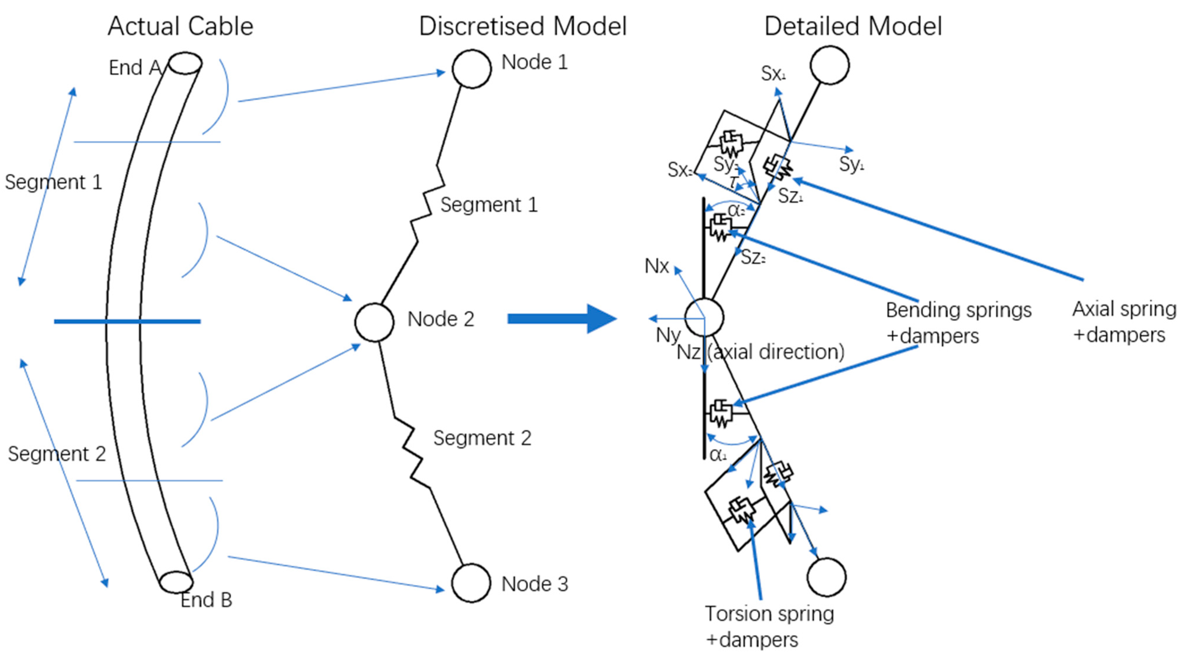
2. Computational Theory

A typical submarine underwater towed system is shown in Figure 2. A typical submarine underwater towed system usually consists of a flexible towed cable with zero or positive buoyancy, a towed body carrying a variety of underwater operational equipment, and a submarine that provides the driving force. In this study, a computational model of underwater towed systems for submersibles with variable cable lengths is developed in conjunction with related studies on motion modeling of underwater towed systems [26,27,28]. The submersible is represented as an underwater vehicle with six degrees of freedom for moving. The towed cable is represented using the lumped mass method in a mathematical manner. The towed body is considered a small-scale mass point model attached to the end of the towed cable at s = 0. The towed body is primarily influenced by its buoyancy, gravity, and resistance to current. The towed cable does not take into account the effects of bending and torsional stiffness. This study examines the accelerated and circular rotating motions of a submarine in a static horizontal plane at a specific water depth, excluding the influence of external factors such as wind, waves, and currents on the towed system, while simultaneously ensuring that the towed object remains submerged throughout maneuvers.

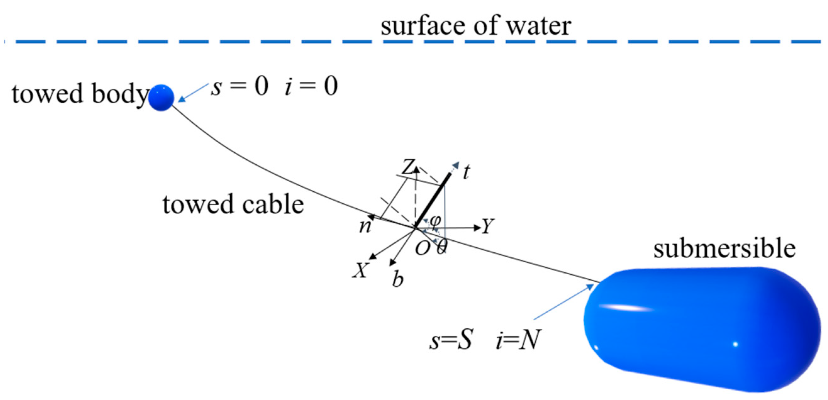
2.1. Coordinate System

The towed body is considered a small-scale mass point model attached to the end of the towed cable at s = 0. The coordinate system is simplified to use the inertial coordinate system O-XYZ and the local coordinate system O-btn, where the towed body and the towed cable are described by the local coordinate system O-btn. Two coordinate systems can be converted using a rotation matrix. The transformation relationship between the inertial coordinate system and the local coordinate system is as expressed in Equation (1).
[ X , Y , Z ] T = E [ b , n , t ] T
E = cos θ sin θ cos ϕ sin θ sin ϕ sin θ cos θ cos ϕ cos θ sin ϕ 0 sin ϕ cos ϕ
In this context, E represents the matrix that converts the local coordinate system into the global coordinate system.

2.2. Governing Equation

The total length of the S towed cable is discretized into N segments by the lumped mass method, and then the dynamic model is established. The process entails dividing the towed cable into N segments by discretizing it from end to end into N + 1 nodes. The end at s = 0 corresponds to the i = 0 node, while the end at s = S corresponds to the i = N node. The arc-length coordinates of these nodes satisfy the condition 0 = s0 < s1 < … < si < si+1 … < sN = S. The equations of motion for the nonlinearity at node i of the towed cable are obtained using Newton’s second law.
M i a i = Δ T i + B i + G i + F D i
where a i = x ¨ i represents acceleration; Δ T i , B i , G i , F D i represent the tension, buoyancy, gravity, and fluid resistance of the towed cable at node i; M i represents the mass matrix; M a , i represents the inertial mass of the towed cable node itself and its added mass; Ma represents the added mass matrix of a simple node. The relationship between M i and M a , i is as follows:
M i = ( μ i 1 / 2 l i 1 / 2 + μ i + 1 / 2 l i + 1 / 2 ) I / 2 + M a , i
M a , i = ( M a , i 1 / 2 + M a , i + 1 / 2 ) / 2
M a = ρ l σ 1 sin 2 θ cos 2 θ cos θ sin θ cos 2 ϕ sin θ cos ϕ sin ϕ cos θ sin θ cos 2 ϕ 1 cos 2 θ cos 2 ϕ cos θ cos ϕ sin ϕ sin θ cos ϕ sin ϕ cos θ cos ϕ sin ϕ cos 2 ϕ
I is a 3 × 3 unit matrix; μ, l, and ρ represent the mass per unit length, the length between nodes, and the cross-sectional area of the towed cable, respectively; the subscript i + 1/2 represents the physical quantity located between node i and node i + 1.
(1)
Tension T can be treated elastically in terms of the stress–strain relationship, and its constitutive relationship can be represented by Hooke’s law.
Δ T i = T i + 1 / 2 T i 1 / 2
T i + 1 / 2 = E σ ε i + 1 / 2 τ i + 1 / 2
ε i + 1 / 2 = ( x i + 1 x i ) 2 + ( y i + 1 y i ) 2 + ( z i + 1 z i ) 2 / l i + 1 / 2 1
where τ represents the unit tangent vector in the direction of cable length; E represents the elastic modulus; ε represents the stress.
(2)
Buoyancy B and gravity G. The buoyancy and gravity at node i can be expressed as follows:
B i + G i = ρ g [ ( l i 1 / 2 σ i 1 / 2 + l i + 1 / 2 σ i + 1 / 2 ) ( l i 1 / 2 μ i 1 / 2 + l i + 1 / 2 μ i + 1 / 2 ) ] / 2
where g represents the acceleration of gravity.
(3)
Fluid drag force FDi. The drag force on the towed cable can be separated into oblique component drag and normal component drag, taking into account the strain impact on the cable. The expression is as follows:
F D i = ( F D i + 1 / 2 + F D i 1 / 2 ) / 2
F D i ρ l d 1 + ε ( C n v n , b v n , b + π C t v t v t )
where v = x ˙ represents the velocity vector of the node; d represents the diameter of the cable; and C n and C t represent the normal and tangential resistance coefficients, respectively.
The motion of the towed body is described using a mass motion model, and its equations of motion control can be obtained by Newton’s second law:
M c A ¨ s = Q
The non-zero elements of the mass matrix are as follows:
M c = m + m c x 0 0 0 m + m c y 0 0 0 m + m c z
A S = X c Y c Z c T
Q = ρ U 2 L x   2 / 2 ρ U 2 L y   2 / 2 ρ U 2 L z   2 / 2 + m g ρ g V
where Matrix As indicates the spatial position of the towed body, with components Xc, Yc, and Zc indicating its position in three coordinate directions within a reference coordinate system; m represents the mass of the towed body; mcx, mcy, and mcz represent the added mass of the towed body. Q is the gravitational buoyancy, inertial force, current action, and towed cable tension acting on the towed body; Lx, Ly, and Lz are the characteristic lengths of the towed body for the calculation of current forces.

2.3. Boundary Conditions

At the location of towed cable i = 0, the towed body is represented as a mass point model and is connected to the end of the towed cable. Combining Equations (2) and (3), the boundary condition here can be written as:
( M 0 + M c ) a 0 = F 0 + Q
where the equation indicated by a subscript of 0 is at node 1, the end of the towed cable.
At the point where the towed cable i = N , it represents the initial end of the towed cable connected to the submersible. The displacement and velocity of the initial end of the towed cable is the same as that of the submersible; thus, x N = x s ( t ) . The velocity of the initial end of the towed cable is when the length of the towed cable changes:
x ˙ N = v s ( t ) + v d r ( t ) τ
where the equation denoted by the subscript N is at the ith node, where i = N. xs represents the trajectory of the nodes of the towed cable and the submarine over time, and vs represents the velocity of the submarine, where vs = dxs/dt. v d τ represents the speed at which the length of the towed cable is changing, with positive values indicating retraction and negative values indicating deployment. τ represents the time-dependent unit tangential vector at point i = N of the towed cable, and τ N 1 / 2 is substituted for τ because τ N 1 / 2 can be readily obtained through direct numerical differentiation.
The initial condition includes the position and velocity of each node on the cable, as described by the following equation:
x i = x 0 x ˙ i = v 0 ( i = 0 , 1 , , N )

2.4. Solution Methods

For towed cables with changing lengths, the number of discrete segments of the towed cable and the number of effective equations of motion need to be dynamically adjusted during the calculation process. Cable segments and nodes are inserted during a cable deployment maneuver and removed during a cable retraction maneuver. The cable length s is determined by the following equation at any given time:
s ( t ) = s 0 0 t v d r ( 1 + ε ) d τ
where s 0 represents the initial length of the towed cable, and ε represents the local strain.
When s j 1 + Δ s < s s j + Δ s , the node ordinal number i at the towed cable node N can be calculated using the following equation:
N j
where j ranges from 1 to N, Δ s = l N 1 / 2 3 ~ l N 1 / 2 2 . When i = N , s N = s ( t ) .
As the flexible towed cable does not account for bending and torsional stiffness effects, Equation (6) can be simplified to:
s ( t ) s 0 0 t v d r d τ
After each time step, the values of s and N can be determined for the current length of the towed cable. The current s and N values are used in Equations (8) and (9) to calculate the arc length and node sequence number at the tow cable position. Continue performing the calculations mentioned above until the towed cable is fully retracted or deployed.
Combining the differential definition of velocity v = d x / d t and associating it with Equation (3) allows the equations of motion of the towed cable to be controlled.
d x ˙ i d t = M i   1 F i d x i d t = x ˙ i ( i = 0 , , N 1 )
The equations of motion control for the underwater towed system of a submersible with varying cable length can be obtained by coupling Equations (3), (5) and (10), which can be solved by using the Runge–Kutta method under the given initial value conditions.

3. Numerical Model Setup

The submersible underwater towed system consists of the submersible, towed cable, and towed body. The structural specifications of the towed cable and towed body are detailed in Table 1. To prevent the towed cable from tangling around the propeller and avoid collisions, the towed cable and body are typically designed to have negative or zero buoyancy. Additionally, the towed cable is attached to the upper section of the submersible to ensure system safety during mission operations. This study focuses on analyzing the tension of the towed cable and the rising and sinking trajectories of the towed body. The simulation is conducted without accounting for the impact of wind, waves, currents, and other variables on the towed system.

4. Results and Discussion

Table 2 shows the categorization for simple and composite manipulation motions. Submersible underwater towed systems can be classified based on whether the length of the towed cable is altered during maneuvering: a simple maneuvering motion in which the submersible performs a maneuvering motion without changing the length of the towed cable, and a composite maneuvering motion in which the submersible performs a maneuvering motion and changes the length of the towed cable at the same time. Simple maneuvering motions are categorized as accelerated motion and circular rotational motion. Composite maneuvering motions involve altering the length of the towed cable during accelerated motion and circular rotational motion.

4.1. Simple Maneuvering Motion

Before investigating the motion response of the system under composite maneuvering motions, it is first necessary to analyze the motion response of a simple maneuvering motion that does not enter into the cable retraction and deployment behavior. The submersible’s speed ranges from 2 kN to 4 kN, and the speed change takes 1500 s. The circular rotational motion speed is 4 kN with a rotational radius of 400 m.
The course of the towed body depth and towed cable tension during the accelerated and circular rotational motions are shown in Figure 3 and Figure 4. In this paper, towed cable tension refers to the tension at the point where the towed cable connects to the submersible. This is the point where the forces on the entire towed system are most concentrated, and understanding and monitoring the tension at this point is critical to ensuring the stability and safety of the system. During accelerated motion, the towed body’s depth stabilizes gradually from one initial depth to another. The inertial effect of the towed body significantly impacts the system’s maneuverability. Once the submersible reaches a constant speed, the tension in the cable stabilizes at a specific level. When the submersible undergoes circular rotational motion, the change in the depth of the towed body and tension in the towed cable can be divided into two phases: an initial phase of a continuously changing transient state, followed by a stable long-term variation. Figure 5 displays the changes in the shape of the towed cable when the submersible undergoes accelerated motion. The cable pattern was recorded at intervals of 100 s, starting from 0 s and continuing throughout the entire 1500 s acceleration duration. The alteration in the shape of the towed cable during the circular rotation was documented at intervals of 25 s, starting from 3000 s and continuing until 3500 s, as depicted in Figure 6.

4.2. Composite Maneuvering Motion

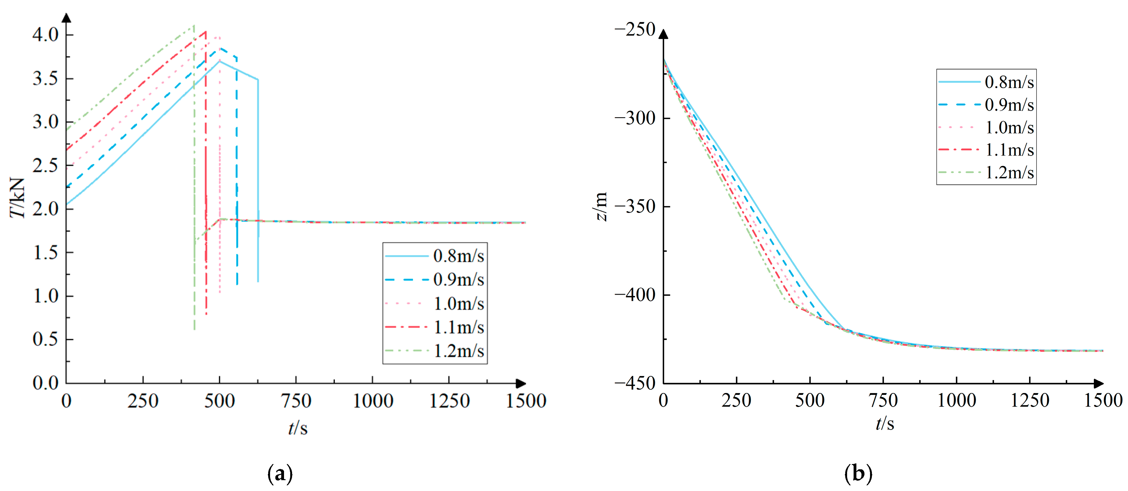
4.2.1. Accelerated Motion

To investigate the impact of various towed cable speeds on motion response during accelerated motion, the towed cable’s initial length is 1000 m, the submersible operates 500 m below the horizontal plane, and the cable speeds are 0.8, 0.9, 1.0, 1.1, and 1.2 m/s. The speed of the retraction and deployment cables is taken from the Zhang literature [20], and this speed satisfies practical engineering applications. The lengths of submersibles under different speeds of towed cable have been adjusted to 500 m, with time and speed range changes matching those in Section 4.1. This study presents the course diagram of motion response during acceleration and the change diagram of motion response during variable speed change cable length. The plot in Figure 7 illustrates the change in shape of the towed cable during the retraction and deployment maneuver while undergoing acceleration. Figure 7a shows the variation of the towed cable shape at a retraction speed of 1.0 m/s. Figure 7b shows the variation of the towed cable shape at the deployment speed of 1.0 m/s.
Figure 8 and Figure 9 illustrate the submersible executing cable retraction and deployment actions while in accelerated motion. The course curves of the depth of towed body motion and towed cable tension for different retraction and deployment speeds. As the deployment maneuver increases the length of the towed cable, the depth of the towed body decreases. The faster the deployment speed, the smaller the towed body depth. The depth of the towed body gradually stabilized at −336 m at different deployment speeds at the end of the cable deployment maneuver. The towed cable experiences a large shock impact at the end of the deployment maneuver, leading to a rapid increase in tension. After executing the retraction maneuver, the depth of the towed body increased linearly and eventually stabilized at −432 m. At the moment of the end of the retraction maneuver, the towed cable is significantly affected by the shock effect, and the towed cable tension is then drastically reduced.
Figure 10 illustrates the motion response values of the towed system while the submersible undergoes accelerated motion and the rate of change of the cable length of the towed cable is altered. Figure 10a shows the maximum tension on the towed cable at different retraction and deployment maneuvering speeds. When the deployment maneuver is performed, with the increase in the towed cable length change speed from 0.8 m/s to 1.2 m/s, the maximum tension of the towed cable first increases and then slightly decreases, and the maximum tension value appears at 1.0 m/s. There are two primary factors contributing to this phenomenon. Firstly, the submersible generates additional inertial force when performing acceleration maneuvers. Secondly, the length of the towed cable continuously increases during the deployment process, and the tension of the cable increases as the rate of change in cable length increases. Upon completion of the deployment maneuver, the towed cable will abruptly cease its release, resulting in a swift and significant alteration in towed cable tension. When the rate of change of the length of the towed cable is 1.0 m/s, the acceleration maneuvering motion of the submersible terminates at the same time as the deployment maneuver of the towed cable. Due to the influence of these two factors, the maximum tension of the towed cable reaches its maximum at this moment. When performing the retraction maneuver, the maximum tension in the towed cable gradually increased as the speed of the cable length change increased. The maximum tension was about 3.6 kN at 0.8 m/s and increased to about 4.2 kN as the speed increased to 1.2 m/s. The tension in the towed cable is caused by a combination of gravity, buoyancy, inertial forces, current resistance, and the forces of retraction and deployment. This tension increases as the speed of the submersible and the rate of change in the length of the towed cable increase. Figure 10b displays the variations in depth of the towed body after different retraction and deployment maneuvers at the conclusion of the towed cable maneuver. In the deployment maneuver, the depth of the towed body increased significantly as the deployment speed increased from 0.8 m/s to 1.2 m/s, with the depth change increasing from about 50 m to about 150 m. During the retraction maneuver, the alteration in speed has a minimal impact on the depth of the towed body, which remains relatively constant at approximately −150 m.
To ensure the accuracy and suitability of the conclusions, it is important to examine the system’s motion response under various structural parameters. The influence of the underwater towed system on motion response in a submersible comes from three sources: the submersible, the towed cable, and the towed body. The submersible’s motion serves as the propulsion for the towed system. The towed cable’s mass per unit length and diameter jointly control its gravity and buoyancy. In order to account for the various designs of towed bodies that are tailored to distinct mission requirements, it is necessary to consider varying drag coefficients and added mass coefficients, in addition to the effects of gravity and buoyancy on the towed body. As shown in Table 3, the ranges of values of motion and structural parameters for the retraction and deployment maneuvers during the accelerated motion of the towed cable system. The drag coefficient of a towed body in an underwater towed system usually ranges from 0.6 to 1.5 [29], while the added mass coefficient normally falls between 0.5 and 2.0 [30].
Figure 11 displays the motion response values of the towed system for different parameters as the submersible is accelerated and the cable length is changed. The lower the maximum tension in the towed cable and the closer the depth of the towed body is to 0 m, the better the safety and motion stability of the towed system. Figure 11a shows that the maximum tension values during the retraction and deployment of the submarine are 3.71 kN and 3.65 kN, respectively, when the acceleration time is 600 s. These values are considerably lower than the corresponding values for other acceleration times. The reason for this is that as the acceleration time increases, the acceleration of the submersible decreases, resulting in a decrease in both inertial force and current resistance. However, the depth of the towed body for the deployment at an acceleration time of 600 s has the largest change of 127 m. From Figure 11b, it is evident that when the buoyancy of the towed body is equivalent to the force of gravity, the maximum tension is minimized, and the depth variation approaches zero meters. When the ratio of buoyancy to gravity of the towed body is 1.0, the maximum tension in the deployment state is 3.67 kN, and the change in depth is 38 m. In the retraction state, the maximum tension is 3.89 kN, and the change in depth is −100 m. It is worth noting that when the ratio of 2.0 is when the deployment of the depth change value is 0, is this an indication of more time to meet the depth change value of 0 m requirements? The answer is no because when the ratio is 2.0 when the towed body is floating in the water, it does not meet the requirements of the towed body submerged in the water. Figure 11c demonstrates that when the drag coefficient of the towed body decreases, the maximum tension also decreases, and the depth variation value deviates further from 0 m. At a resistance coefficient of 0.6, the maximum tension experienced during deployment is 3.71 kN, while the greatest tension during retraction is 3.01 kN. On the other hand, when the resistance coefficient is 1.5, the depth change during deployment is 90 m, and the maximum tension during retraction is −161 m. According to Figure 11d, the added mass coefficient of the towed body solely impacts the maximum tension during the deployment maneuver. The maximum tension decreases as the added mass coefficient decreases. When the added mass coefficient is 0.5, the maximum tension is 3.90 kN. According to Figure 11e, when the buoyancy force per unit length of the towed cable is equal to gravity, the maximum tension of the cable is at its minimum, and the depth change is closer to 0. The maximum tension at the time of retraction is 4.01 kN, and the value of the depth change is −117 m. The maximum tension at the time of deployment is 3.94 kN, and the value of the depth change is 81 m. This occurs when the buoyancy force per unit length of the towed cable is in equilibrium with the force of gravity, resulting in the cancellation of these two forces. As a result, the pull at the first end of the towed cable is reduced.

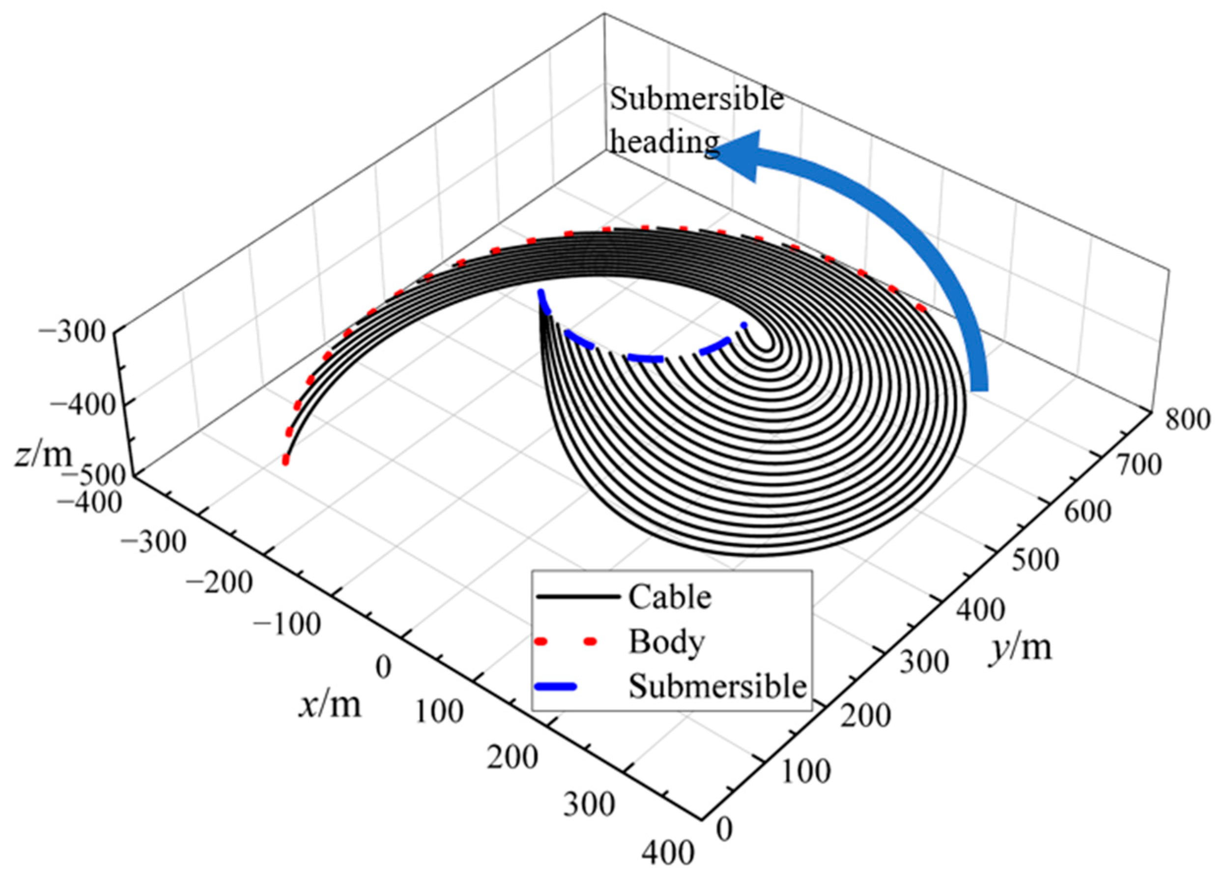
4.2.2. Circular Rotational Motion

The circular rotational radius and rotational speed are determined by Section 4.1, while the initial cable length, retraction and deployment speed, submersible depth, and cable length variation range are in accordance with Section 4.2.1. When the submersible is performing circular rotational motion, the motion response of the towed system is divided into two phases: transient and long-periodic steady states. When the submersible is performing circular rotational motion, the motion response of the towed system is divided into two phases: transient and long-periodic steady states. This study aims to analyze the motion response of the towed system during the steady-state period under the towed cable maneuver. The towed cable maneuver is carried out only after the towed system enters steady-state operation, so the towed cable maneuver is chosen to be carried out 3000 s after the start of the simulation. As shown in Figure 12, the variation of towed cable shape during the retraction and deployment maneuver during the rotational motion is plotted. Figure 12a shows the variation of the towed cable shape at a retraction speed of 1.0 m/s. Figure 12a shows the variation of the towed cable shape at the deployment speed of 1.0 m/s.
Figure 13 and Figure 14 demonstrate the submersible engaging in cable deployment and retraction actions while executing circular rotational movement. The figures depict variations in towed body motion depth and towed cable tension at varying deployment and retraction speeds. During the deployment maneuver, the towed body depth change progresses through three distinct phases: linear variation from the start to the end of the maneuver, followed by a reverse linear variation, and finally a transition phase where the depth gradually stabilizes to a long-periodic variation. Shock effects impact the towed cable at the start and finish of the deployment movement. The tension in the towed cable varies significantly, increasing as the line is deployed at a higher rate. The depth of the towed body varies rapidly with the retraction maneuver when the retraction maneuver is performed. At the end of the retraction maneuver, the towed body depth gradually returns to a steady state with long periodic variations. During the retraction maneuver, the towed cable has a shock effect at the start and end of the process. The tension in the towed cable experiences considerable fluctuations at the start and end of the retraction process, with the magnitude of the shift being proportional to the speed of retraction. Comparing the towed body depth change during retraction and deployment reveals that the towed body depth requires more time to stabilize during deployment.
Figure 15 displays the variations in motion response induced by the submersible while executing circular rotating motion and cable retraction and deploying processes. Figure 15a shows the maximum tension of the towed cable during circular rotational motion at different retraction and deployment maneuvering speeds. The maximum tension values for both retraction and deployment were 1.66 kN and 2.39 kN at a rate of variation of 1.2 m/s in cable length. While the maximum tension is reached when the rate of change of cable length is at its peak, the rise in maximum tension does not directly correspond to the increase in the rate of change of cable length. This is due to the fact that the variation of the towed cable tension during the submersible circular rotational motion shows an obvious long periodicity and the time of the maximum tension appearing at different rates of cable length change is not consistent. The maximum tension can be greatly diminished if the alteration in cable length concludes at the minimum point of the tension fluctuation cycle. Figure 15b shows the change in towed cable depth at the completion of a maneuver when retracting and deploying are carried out during the steady condition of circular rotating motion. A higher rate of cable length change during retraction results in a lesser depth change. At a cable retraction speed of 0.8 m/s, the depth change of the towed body is −148 m. A higher rate of change in cable length during deployment results in a larger difference in depth. When the cable is deployed at a speed of 1.2 m/s, the depth of the towed body varies by 147 m.
To examine the impact of various maneuvering and structural parameters on the motion response during circular rotation, the range of parameters used is essentially identical to that specified in Table 3. The “acceleration time/s” is replaced by “rotational speed/kN”, and the value ranges are 2 kN, 4 kN, 6 kN, and 8 kN. Figure 16 displays the motion response values of the towed system when the submersible circular rotational motion and cable length are changed.
Figure 16a illustrates that the submersible rotational speed is 8 kN. The maximum tension values during recovery and deployment are the largest, and the drag body depth variation values are closer to 0, which are 6.35 kN, 5.33 kN, −41 m, and 41 m. The increase in maximum tension with increasing speed is well understood. The reason that the value of the depth variation of the towed body decreases at higher rotational speeds is that at high towed speeds, the lift and drag effects of the fluid surrounding the towed body and the inertial forces of the system are enhanced. These forces will balance the motion of the towed body to some extent and stabilize it in a certain depth range, thereby reducing the cyclic variation in depth. In Figure 16b, it can be observed that when the buoyancy-to-gravity ratio of the towed body is 1.0, the maximum tension values of the towed cable are at their minimum for both the retracting and deploying cables. Additionally, the depth change of the towed body is closer to 0 m, with values of −46 m and 38 m. The corresponding tension values for these depths are 2.27 kN and 1.31 kN, respectively. In Figure 16c, it is evident that the maximum tension during deployment remains relatively constant despite variations in the towed body resistance coefficient. As depicted in Figure 16d, the added mass coefficient of the towed body solely impacts the maximum tension during the deployment maneuver. A smaller added mass coefficient results in a correspondingly smaller maximum tension. When the added mass coefficient is 0.5, the maximum tension is 1.76 kN. From Figure 16e, when the buoyancy force per unit length of the towed cable is equal to gravity, the maximum tension of the towed cable is the smallest, and the value of the depth change is closer to 0 m.

5. Conclusions

The article simulates and analyzes the motion response of a submersible underwater towed system during retracting and deploying cable maneuvers. It examines simple maneuvering motions with accelerated and circular rotational motions, as well as composite maneuvering motions involving retracting and deploying cable maneuvers, using a cable dynamics computational tool. The towed body depth and towed cable tension history curves were obtained for the towed system in different maneuvering motions. The value of the change in kinematic response under composite maneuvering motion is calculated. The laws regarding the impact of varying rates of cable length change on the kinematic response during submersible maneuvering motions are outlined. To ensure wider applicability of the conclusions, the effects of different maneuvering and structural parameters on motion response are discussed.
(1)
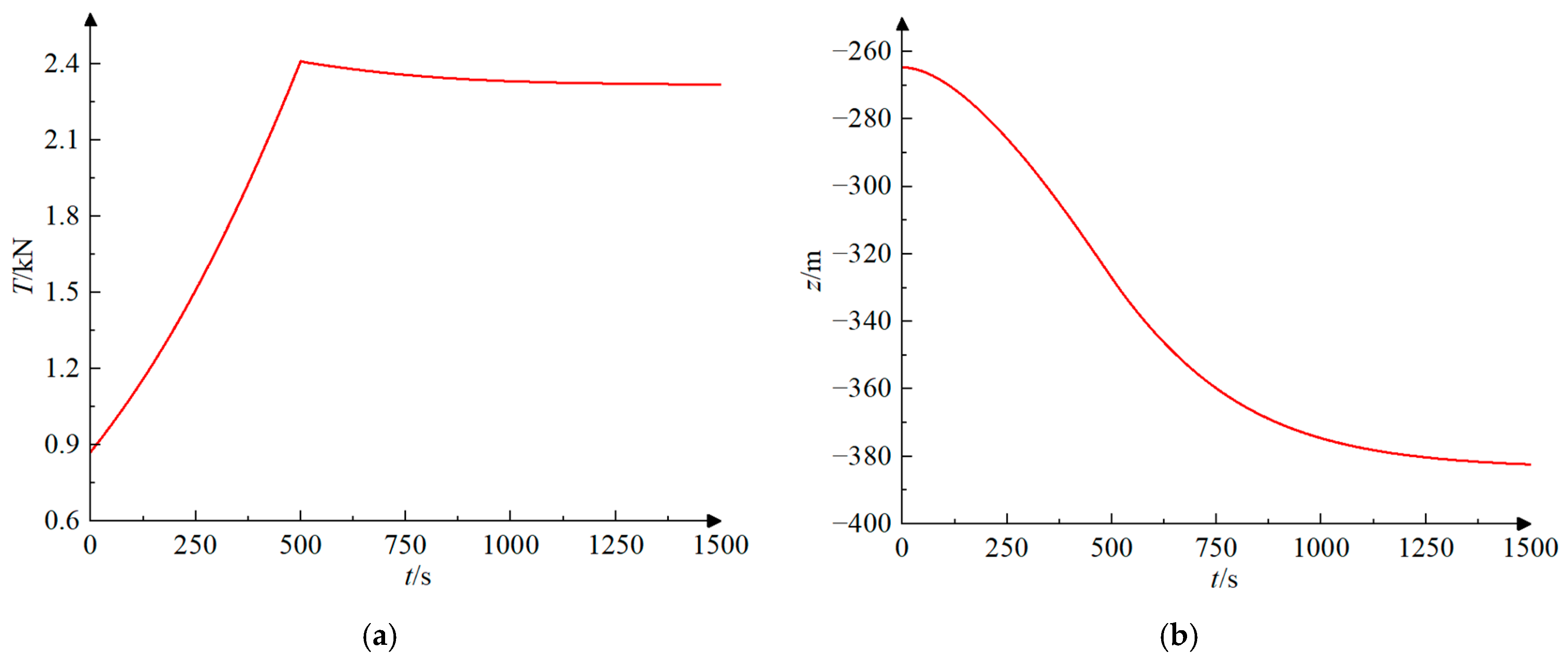
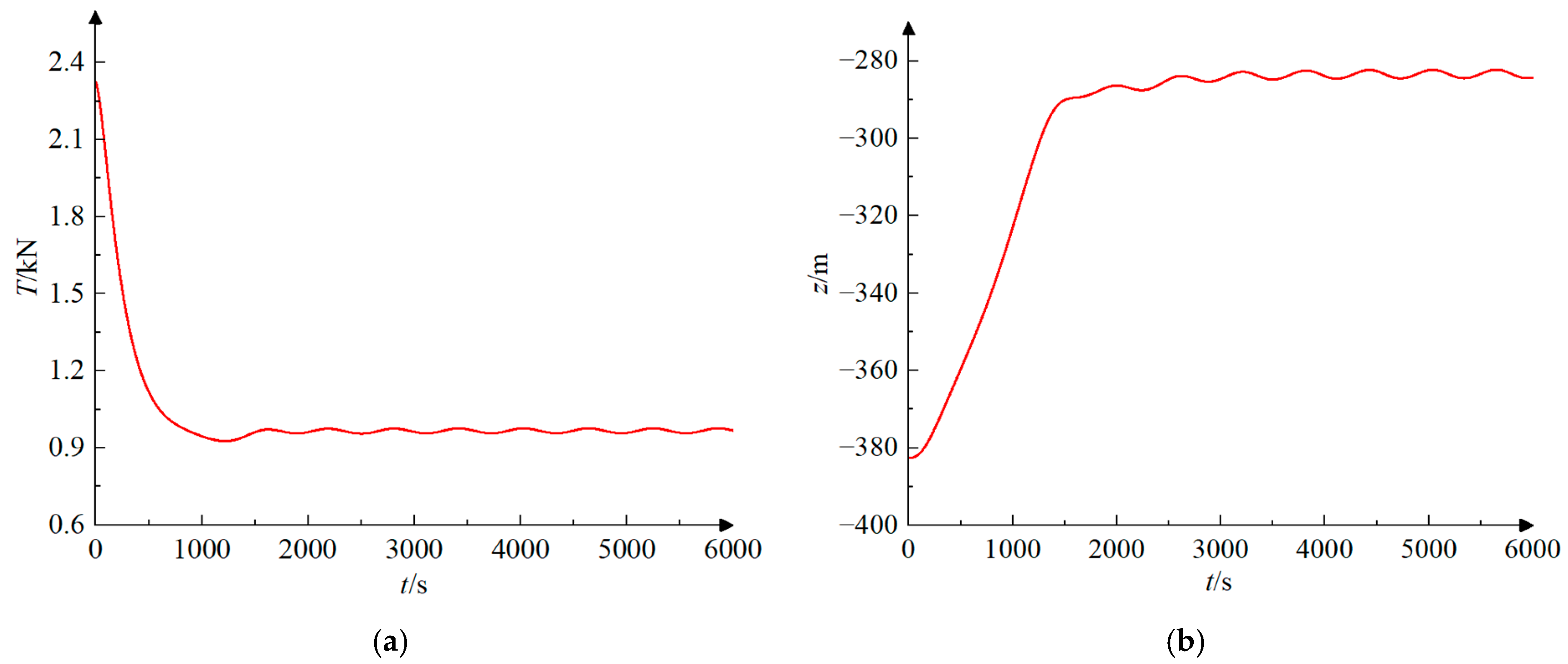
At the end of the retraction maneuver and the deployment maneuver, rapid and substantial fluctuations in tension occur at the point where the towed cable connects to the submersible.
(2)
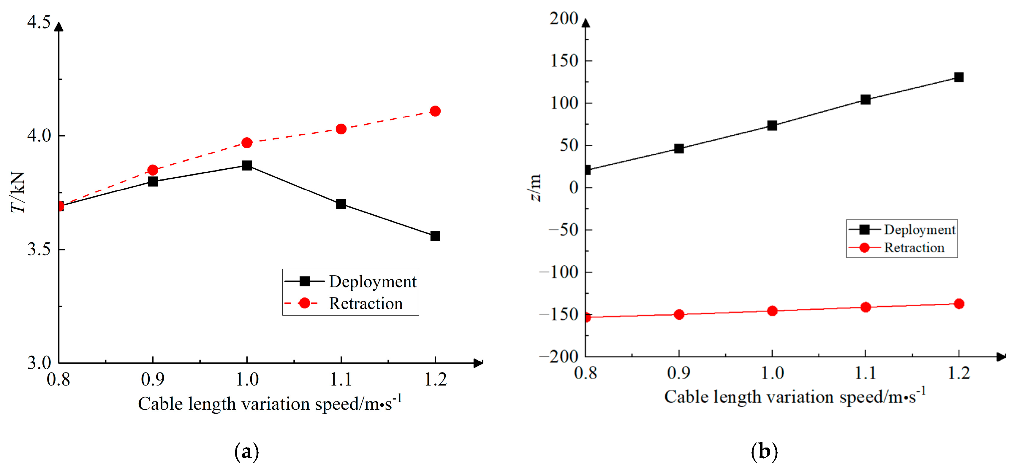
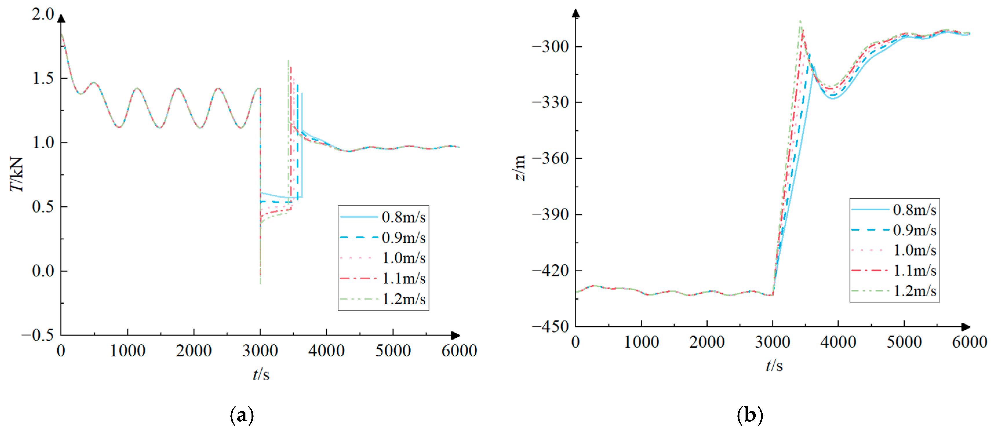
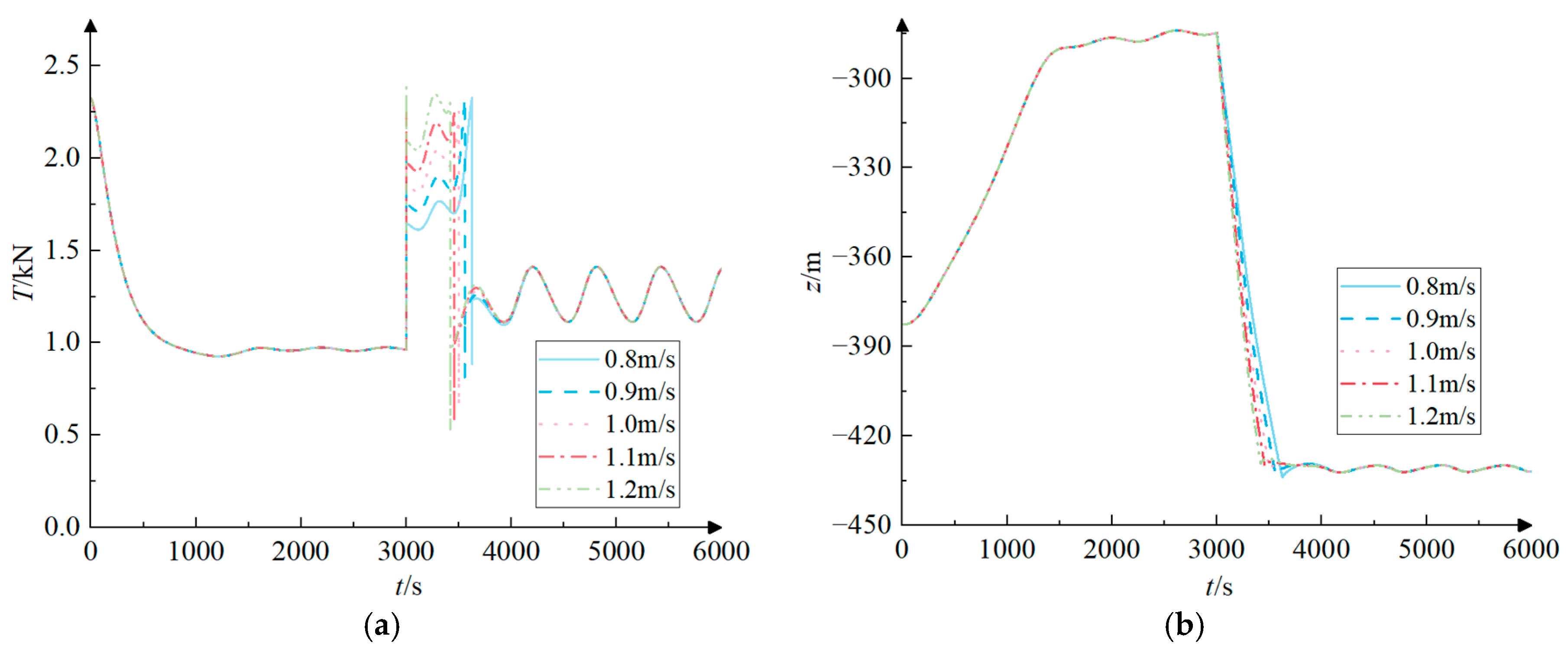
When performing retraction maneuvers or deployment maneuvers during submersible acceleration, the simultaneous end of submersible acceleration and towed cable length change is avoided by selecting a suitable rate of cable length change. This can effectively reduce the maximum tension of the towed cable. During the deployment maneuver, as the length of the towed cable rises, the speed of the cable change also increases from 0.8 m/s to 1.2 m/s. This results in an initial increase and subsequent minor drop in the maximum tension of the towed cable. The maximum tension value occurs at a speed of 1.0 m/s. This is because the acceleration of the submersible ends at the same time as the cable length change at the towed cable length change speed of 1.0 m/s.
(3)
When the cable deployment maneuver was performed during the circular rotational motion, the range of tension variation was reduced from 0.30 kN before the deployment to 0.02 kN after the deployment. The stability of the towed cable tension at the end of the deployment was significantly enhanced. During the cable deployment process, the faster the cable length change speed, the larger the towed body depth change amount. An increase in towed cable length increases the total mass and inertia of the system. Increased inertia of the system results in less sensitivity to external forces, leading to a reduction in the magnitude of tension variations. At the same time, a longer towed cable has a larger surface area in contact with the water column, the damping effect of the fluid is more significant, and the tension will gradually decay as it propagates. This is because energy is absorbed and dispersed during propagation, thus reducing tension fluctuations.
(4)
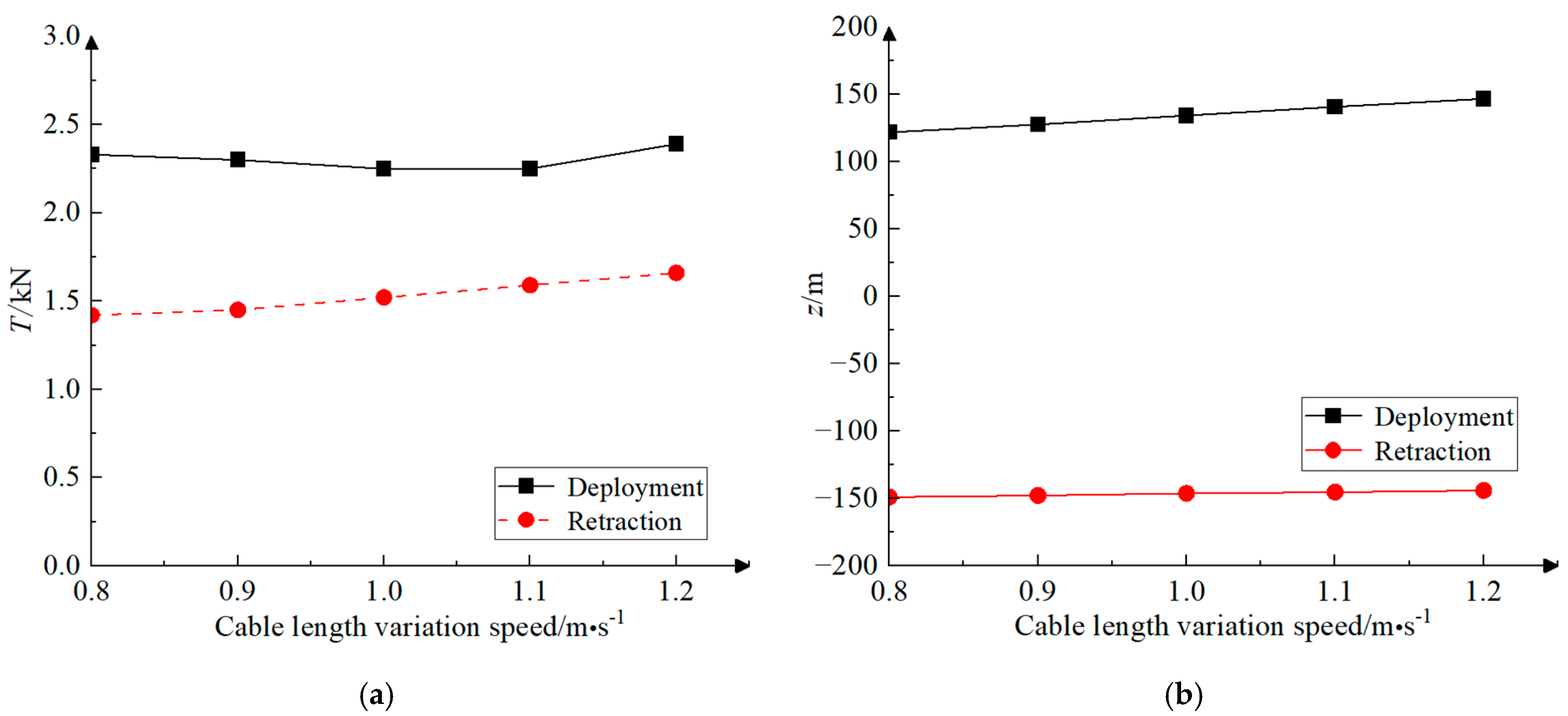
The maximum tension of the towed cable in the circular rotational motion occurs at the rate of change of the cable length of 1.2 m/s at different rates of change of the cable length, and the maximum tension values of the retraction and deployment of the cable are 1.66 kN and 2.39 kN. While the maximum tension is reached when the rate of change of cable length is at its maximum, the rise in maximum tension does not directly correspond to the increase in the rate of change of cable length. This is due to the fact that the variation of the towed cable tension during the submersible circular rotational motion shows an obvious long periodicity and the time of the maximum tension appearing at different rates of cable length change is not consistent. The maximum tension can be greatly diminished if the alteration in cable length concludes at the minimum point of the tension fluctuation cycle.
(5)
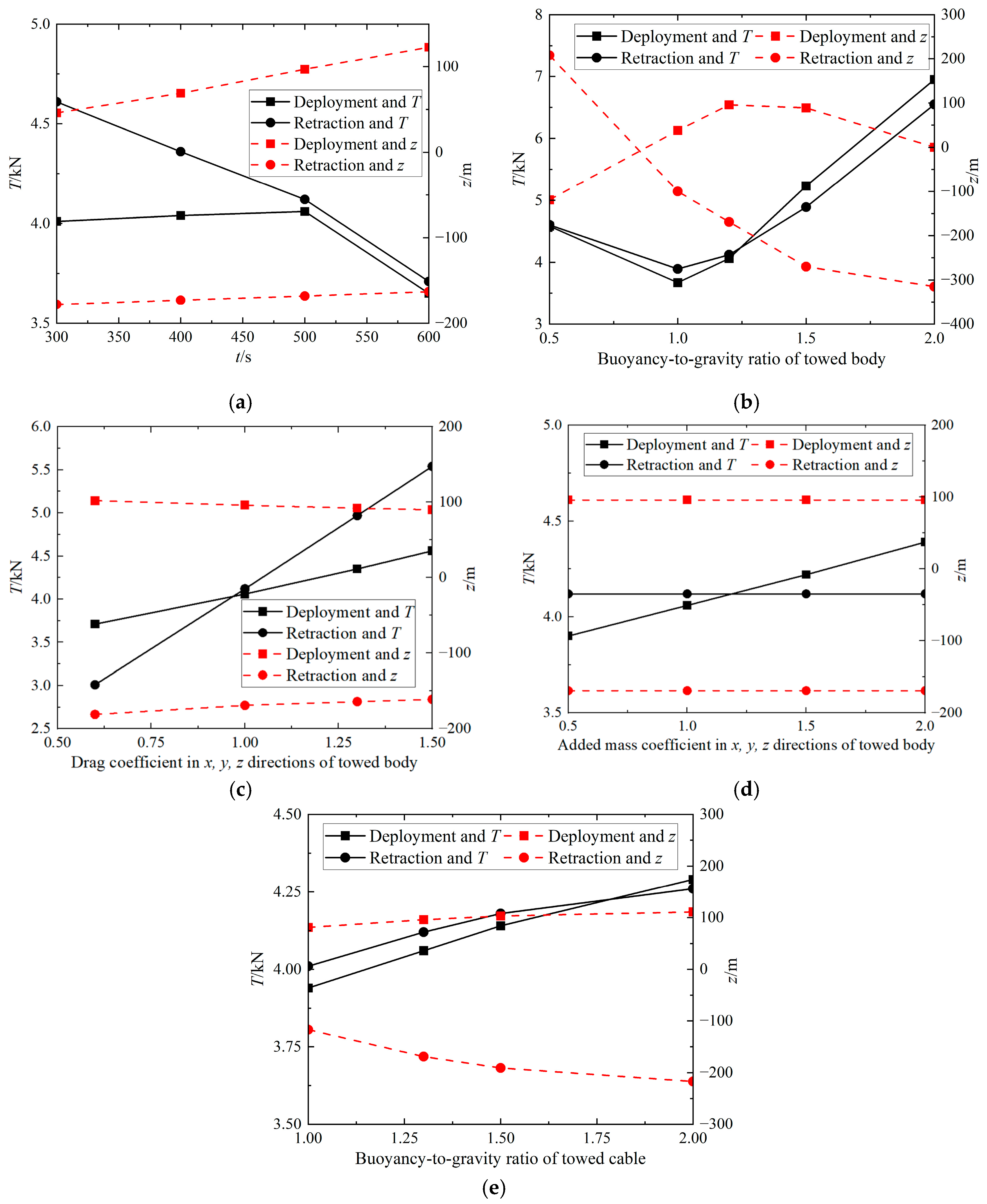
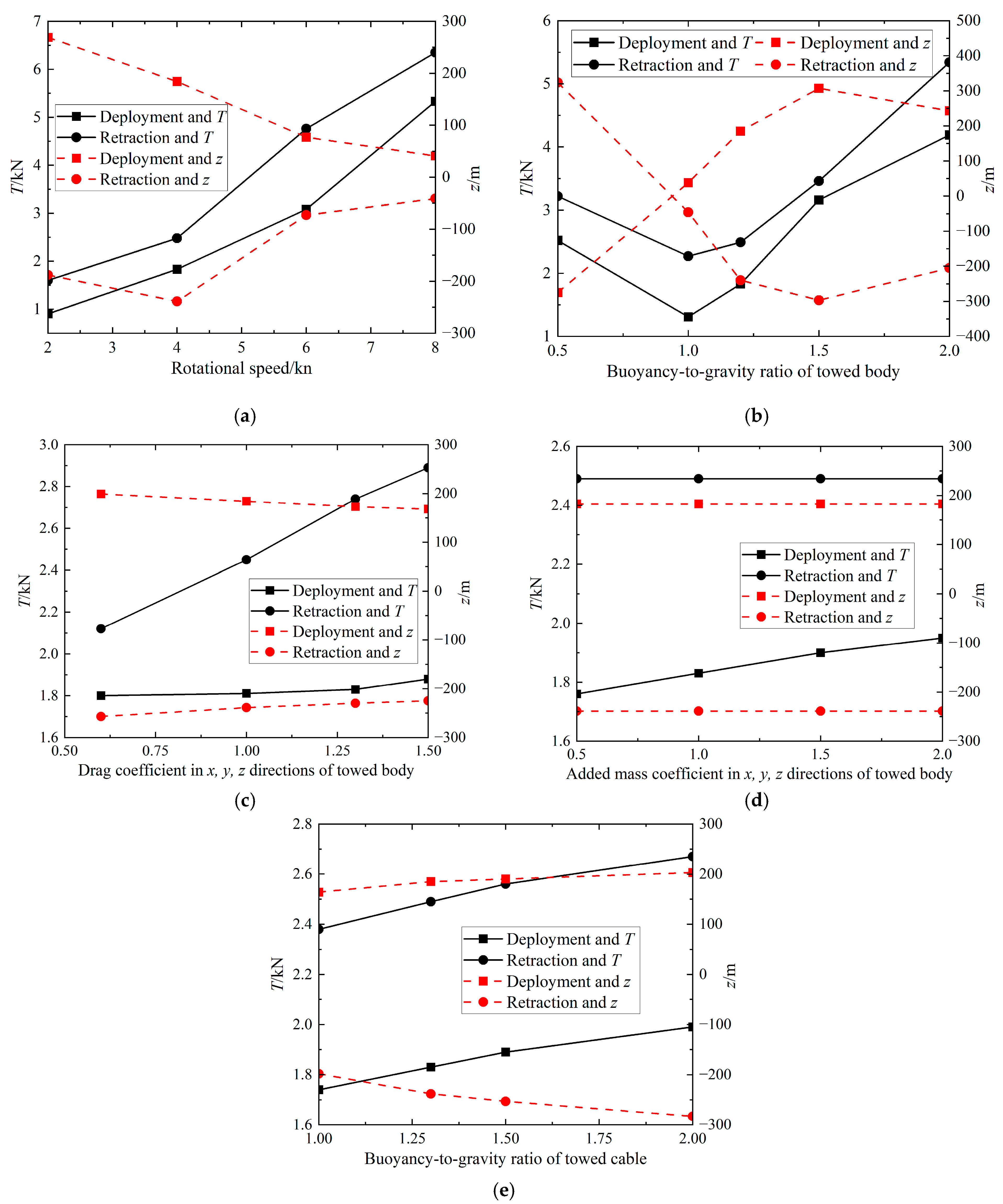
This paper considers the effects of various motion parameters and structural parameters on the motion response of composite maneuvering motion. Specifically, the buoyancy-to-gravity ratio of the towed body, the drag coefficient of the towed body, the added mass coefficient of the towed body, the buoyancy-to-gravity ratio of the towed cable, the acceleration time of the acceleration motion, and the rotational speed of the circular rotational motion are taken into account. Parameters such as the buoyancy-to-gravity ratio of the towed body, the acceleration time of the acceleration motion, and the rotational speed of the circular rotational motion have a notable impact on the motion response.

Author Contributions

Conceptualization, Z.W. and P.K.; methodology, Z.W.; software, P.K.; validation, Z.W.; formal analysis, Z.W.; investigation, P.K.; resources, Z.W.; data curation, P.K.; writing—original draft preparation, P.K.; writing—review and editing, Z.W.; visualization, P.K.; supervision, Z.W.; project administration, P.K.; funding acquisition, Z.W. All authors have read and agreed to the published version of the manuscript.

Funding

This research was funded by the National Natural Science Foundation of China, grant number 51709133.

Data Availability Statement

The datasets generated and/or analyzed during the current study are not publicly available due to privacy or ethical restrictions but are available from the corresponding author upon reasonable request.

Conflicts of Interest

The authors declare no conflicts of interest.

References

  1. Grosenbaugh, M.; Bowen, A. A Case for Active Control of Underwater Vehicles Towed by Very Long Marine Cables. In Proceedings of the ISOPE International Ocean and Polar Engineering Conference, Seoul, Republic of Korea, 19–24 June 2005. ISOPE-I-05-166. [Google Scholar]
  2. Walker, K.L.; Giorgio-Serchi, F. Disturbance Preview for Non-Linear Model Predictive Trajectory Tracking of Underwater Vehicles in Wave Dominated Environments. In Proceedings of the 2023 IEEE/RSJ International Conference on Intelligent Robots and Systems (IROS), Detroit, MI, USA, 1–5 October 2023; pp. 6169–6176. [Google Scholar]
  3. Vaz, M.A.; Patel, M.H. Transient behaviour of towed marine cables in two dimensions. Appl. Ocean Res. 1995, 17, 143–153. [Google Scholar] [CrossRef]
  4. Wang, Z. Towed Cable System Vibration Responses to Varying Towed Velocity. Nav. Archit. Ocean Eng. 2019, 35, 1–7. [Google Scholar] [CrossRef]
  5. Grosenbaugh, M.A. Dynamic Behavior of Towed Cable Systems During Ship Turning Maneuvers. Ocean Eng. 2007, 34, 1532–1542. [Google Scholar] [CrossRef]
  6. Zhang, D.; Bai, Y.; Zhu, K. Dynamic analysis for towed cable under two different modes. J. Ship Mech. 2018, 22, 967–976. [Google Scholar] [CrossRef]
  7. Ablow, C.M.; Schechter, S. Numerical simulation of undersea cable dynamics. Ocean Eng. 1983, 10, 443–457. [Google Scholar] [CrossRef]
  8. Liu, L.; Zhang, Y.; Cha, Z. Math-model of Three-dimensional Dragging with Changing Velocity. Ship Eng. 2003, 25, 25–27. [Google Scholar] [CrossRef]
  9. Gong, L.; Wang, W.; Li, S. Investigations on Linear Manoeuvres of Underwater Towed Cable in Current. J. Phys. Conf. Ser. 2020, 1549, 420–433. [Google Scholar] [CrossRef]
  10. Zhao, Y.; Li, G.; Lian, L. Numerical model of towed cable body system validation from sea trial experimental data. Ocean Eng. 2021, 226, 108859. [Google Scholar] [CrossRef]
  11. Chapman, D.A. Towed cable behaviour during ship turning manoeuvers. Ocean Eng. 1984, 11, 327–361. [Google Scholar] [CrossRef]
  12. Wang, Z.; Sun, G. Parameters influence on maneuvered towed cable system dynamics. Appl. Ocean Res. 2015, 49, 27–41. [Google Scholar] [CrossRef]
  13. Kishore, S.S.; Ganapathy, C. Analytical investigations on loop-manoeuvre of underwater towed cable-array system. Appl. Ocean Res. 1996, 18, 353–360. [Google Scholar] [CrossRef]
  14. Wang, H.; Wang, Q. Study on dynamic model of underwater towed heave compensation system. Ocean Eng. 2008, 26, 77–83. [Google Scholar] [CrossRef]
  15. Lu, Z.; Zhu, K. Dynamic Simulation of System of Ocean Changeable Cable in Three Dimensions. J. Jiangsu Univ. Sci. Technol. (Nat. Sci. Ed.) 2003, 17, 6–11. [Google Scholar] [CrossRef]
  16. Yu, S.; Li, Y.; Zhang, Y. Forecast of a floating detector’ s towing state. Ocean Eng. 2015, 3, 45–50. [Google Scholar] [CrossRef]
  17. Pang, S.-K.; Liu, J.-Y.; Chen, H.; Wang, J.; Yi, H. Analysis of motion state of the tow-part underwater towed vehicle system during cable deployment. In Proceedings of the OCEANS 2017—Aberdeen, Aberdeen, UK, 19–22 June 2017; pp. 1–5. [Google Scholar] [CrossRef]
  18. González, F.; de la Prada, A.; Luaces, A. Real-time simulation of cable pay-out and reel-in with towed fishing gears. Ocean Eng. 2017, 131, 295–307. [Google Scholar] [CrossRef]
  19. Quan, W.; Chang, Q.; Zhang, Q. Dynamics calculation for variable-length underwater cable with geometrically nonlinear motion. Ocean Eng. 2020, 212, 107–126. [Google Scholar] [CrossRef]
  20. Zhang, D.; Zhao, B.; Zhu, K. Dynamic analysis of towed cable with variable length during turning maneuvers. Sci. Rep. 2023, 13, 352–362. [Google Scholar] [CrossRef] [PubMed]
  21. Walton, T.S.; Polachek, H. Calculation of transient motion of submerged cables. Math. Comput. 1960, 14, 27–46. [Google Scholar] [CrossRef]
  22. Kato, N.; Koda, S.; Takahashi, T. Motions of underwater towed system. Int. Offshore Mech. Arct. Eng. 1986, 5, 426–433. [Google Scholar]
  23. Toshio, N.; Motora, S.; Fujino, M. On the dynamic analysis of multi-component mooring lines. In Proceedings of the Offshore Technology Conference OTC, Houston, TX, USA, 4 May 1982. [Google Scholar]
  24. Huang, S. Dynamic analysis of three-dimensional marine cable. Ocean Eng. 1994, 21, 587–605. [Google Scholar] [CrossRef]
  25. Chai, Y.T.; Varyani, K.S.; Barltrop, N.D.P. Three-dimensional Lump-Mass formulation of a catenary riser with bending, torsion and irregular seabed interaction effect. Ocean Eng. 2002, 29, 1503–1525. [Google Scholar] [CrossRef]
  26. Wang, F.; Huang, G.; Deng, D. Dynamic response analysis of towed cable during deployment/retrieval. J. Shanghai Jiaotong Univ. (Sci.) 2008, 13, 245–251. [Google Scholar] [CrossRef]
  27. Wang, F.; Tu, W.; Deng, D. Motion Modeling and Numerical Simulation Study of Underwater Multi-Cable Multi-Body Towed System. J. Shanghai Jiaotong Univ. 2020, 54, 441–450. [Google Scholar] [CrossRef]
  28. Wang, Z. Simulation for random vibration transfer and isolation of a multi-segment towed system. J. Vib. Shock 2019, 38, 259–264. [Google Scholar] [CrossRef]
  29. Wang, Z. Dynamics and Design of Ocean Towing Systems; National Defense Industry Press: Beijing, China, 2019; pp. 8–16. [Google Scholar]
  30. Dong, R.G. Effective Mass and Damping of Submerged Structures; Lawrence Livermore National Lab: Livermore, CA, USA, 1978; pp. 40–47. [Google Scholar] [CrossRef]
Figure 1. Actual cable and lumped mass method models.
Applsci 14 06503 g001
Figure 2. Diagram of submersible underwater towed system.
Applsci 14 06503 g002
Figure 3. The course of the motion response of a towed system in accelerated motion. (a) The trend of tension in the towed cable over time; (b) The trend of the depth of the towed body over time.
Applsci 14 06503 g003
Figure 4. The course of the motion response of a towed system in circular rotational motion. (a) The trend of tension in the towed cable over time; (b) The trend of the depth of the towed body over time.
Applsci 14 06503 g004
Figure 5. Changes in cable shape of the towed cable during acceleration motion of the submersible.
Applsci 14 06503 g005
Figure 6. Changes in cable shape of the towed cable during circular rotational motion of the submersible.
Applsci 14 06503 g006
Figure 7. Changes in cable shape of the towed cable at a retraction and deployment speed of 1.0 m/s during acceleration of the submersible. (a) Cable shape change of towed cable during retraction; (b) Cable shape change of towed cable during deployment.
Applsci 14 06503 g007
Figure 8. The motion response history of the towed system for different cable deployment speeds during the accelerated motion of the submersible. (a) The trend of tension in the towed cable over time; (b) The trend of the depth of the towed body over time.
Applsci 14 06503 g008
Figure 9. The motion response history of the towed system for different cable retraction speeds during the accelerated motion of the submersible. (a) The trend of tension in the towed cable over time; (b) The trend of the depth of the towed body over time.
Applsci 14 06503 g009
Figure 10. The motion response values of the towed system when the rate of change of the length of the towed cable varies during the accelerated motion of the submersible. (a) The maximum tension of the towed cable; (b) The difference in depth variation of the towed body.
Applsci 14 06503 g010
Figure 11. The motion response values of the traction system corresponding to different parameters when the submersible accelerated motion and cable length are varied. (a) Acceleration time; (b) Buoyancy-to-gravity ratio of towed body; (c) Drag coefficient in x, y, z directions of towed body; (d) Added mass coefficient in x, y, z directions of towed body; (e) Buoyancy-to-gravity ratio of towed cable.
Applsci 14 06503 g011
Figure 12. Changes in cable shape of the towed cable at a retraction and deployment speed of 1.0 m/s during rotational motion of the submersible. (a) Cable shape change of towed cable during retraction; (b) Cable shape change of towed cable during deployment.
Applsci 14 06503 g012
Figure 13. The motion response history of the towed system for different cable deployment speeds during the circular rotational motion of the submersible. (a) The trend of tension in the towed cable over time; (b) The trend of the depth of the towed body over time.
Applsci 14 06503 g013
Figure 14. The motion response history of the towed system for different cable retraction speeds during the circular rotational motion of the submersible. (a) The trend of tension in the towed cable over time; (b) The trend of the depth of the towed body over time.
Applsci 14 06503 g014
Figure 15. The motion response values of the towed system when the rate of change of the length of the towed cable varies during the circular rotational motion of the submersible. (a) The maximum tension of the towed cable; (b) The difference in depth variation of the towed body.
Applsci 14 06503 g015
Figure 16. The motion response values of the traction system corresponding to different parameters when the submersible circular rotational motion and cable length are varied. (a) Rotational speed; (b) Buoyancy-to-gravity ratio of towed body; (c) Drag coefficient in x, y, z directions of towed body; (d) Added mass coefficient in x, y, z directions of towed body; (e) Buoyancy-to-gravity ratio of towed cable.
Applsci 14 06503 g016
Table 1. Parameters of underwater submersible towed system.
Structural ParametersParameter Value
Initial cable length/m1000
Cable diameter/m0.0165
Mass   per   unit   length / kg · m−10.1711
Tangential drag coefficient of towed cable0.0080
Normal drag coefficient of towed cable1.5000
Towed mass/kg390
Displacement volume of towed body/m30.4254
Drag coefficient in x, y, z directions of towed body1.0000
Added mass coefficient in x, y, z directions of towed body1.0000
Table 2. Classification of maneuvering motion.
Cable Retraction and DeploymentNo Cable Retraction and Deployment
AcceleratedmotionComposite maneuvering motionsSimple maneuvering motion
Circular rotational motionComposite maneuvering motionsSimple maneuvering motion
Table 3. The ranges of values of motion and structural parameters for the retraction and deployment maneuvers during the accelerated motion of the towed cable system.
Motion and Structural ParametersRanges of Values
Acceleration time/s300, 400, 500, 600
Buoyancy-to-gravity ratio of towed body0.5, 1.0, 1.2, 1.5, 2.0
Drag coefficient in x, y, z directions of towed body0.6, 1.0, 1.3, 1.5
Added mass coefficient in x, y, z directions of towed body0.5, 1.0, 1.5, 2.0
Buoyancy-to-gravity ratio of towed cable1.0, 1.3, 1.5, 2.0
Disclaimer/Publisher’s Note: The statements, opinions and data contained in all publications are solely those of the individual author(s) and contributor(s) and not of MDPI and/or the editor(s). MDPI and/or the editor(s) disclaim responsibility for any injury to people or property resulting from any ideas, methods, instructions or products referred to in the content.

