Article

High-Precision Pointing and Tracking System Design for Near-Space Balloon-Based Optical Observation

1
Aerospace Information Research Institute, Chinese Academy of Sciences, Beijing 100190, China
2
School of Optoelectronics, University of Chinese Academy of Sciences, Beijing 100049, China
3
Key Laboratory of Computational Optical Imaging Technology, Chinese Academy of Sciences, Beijing 100190, China
*
Author to whom correspondence should be addressed.
Appl. Sci. 2024, 14(15), 6531; https://doi.org/10.3390/app14156531
Submission received: 20 June 2024 / Revised: 7 July 2024 / Accepted: 8 July 2024 / Published: 26 July 2024
(This article belongs to the Collection Optical Design and Engineering)

Abstract

:
Near-space high-altitude balloon-based platforms have a series of advantages and provide superior conditions for optical observation. In order to ensure the stability of the optical axis of the optical detection load and stable tracking of the target, a near-space high-altitude balloon-based high-precision pointing and tracking system was designed, which can compensate for changes in the pitch angle and azimuth angle of the platform during flight. The system includes a primary platform stable pointing system and a secondary precise tracking system. In the finished flight experiment, the primary platform pointing system and secondary precise tracking system on the balloon-based observation platform worked normally, providing a guarantee for the coronagraph’s stable tracking and detection of the sun. The primary platform pointing system can realize ±1° pointing accuracy, and the simulated accuracy of the secondary precise tracking system is 4″, which guaranteed that the coronagraph obtained more than 20,000 images. In subsequent works, we will upgrade and optimize the whole system and conduct our next flight experiment in the future.

1. Introduction

As a new type of low-speed and stable unmanned aerial vehicle (UAV), high-altitude balloons have the advantages of long dwell time, strong loading capacity, and flexible flight, making them an effective supplement to traditional aviation aircrafts and satellites [1,2]. Near space refers to the space from 20 km to 100 km; the atmosphere is thin, and the water vapor influence, atmospheric refraction, and scattering on optical observation is very small, providing superior optical observation conditions [3,4].
Compared with traditional ground-based and space-based optical observation platforms, near-space high-altitude balloon-based optical observation platforms have a series of advantages:
(1) Superior observation conditions. The optical detection system based on near space has a wider spectral range and can achieve detection resolution close to that of a satellite-based space telescope [5];
(2) Long detection distance. Compared to a ground-based optical system, a high-altitude balloon-based platform is less affected by the Earth’s curvature and can detect targets at longer distances, and it is not affected by ground factors, such as buildings, mountains, and human activities [3];
(3) Strong concealment. On the one hand, the vast majority of fixed-wing aircraft and ground-to-air missiles are currently unable to reach this altitude; on the other hand, the thin film structure of the balloon itself also increases detection difficulty [4];
(4) Low launch and maintenance costs. Compared to space optical detection platforms, the launch and maintenance costs of floating optical detection platforms are low. High-altitude balloons have lower launch costs. They can also be recycled and the system using parachutes be reused alongside the use of other recycling technologies [5].
Typical near-space balloon-based optical detection experiments performed in recent years are shown in Table 1. The United States has the most outstanding development in the field of near-space balloon-based optical detection, with a strong capacity reaching up to several tons, a long duration exceeding one year, high azimuth accuracy, and stable attitude control [6,7,8]. In recent years, the United States has implemented many optical detection projects based on near-space spaceborne observation platforms. In these detection projects, the altitude range of balloon flight ranges from 30 km to 40 km, and the optical observation spectrum includes the ultraviolet spectrum, visible spectrum, and infrared spectrum [9,10,11,12].
The typical representative of near-space optical observations is the balloon-borne large-aperture submillimeter series telescope (BLAST, Pittsboro, NC, USA). BLAST adopts a coaxial Cassegrain optical system, including a primary mirror with a diameter of 1.9 m and a secondary mirror with a diameter of 0.4 m. BLAST has made two successful flights, departing from the Arctic in 2005 and Antarctica in 2006, achieving the first high-resolution and large-scale submillimeter imaging in near space [13,14,15,16]. In 2010 and 2012, BLAST-Pol completed two near-space flight tests around Antarctica at the McMurdo Station to observe the situation of the Milky Way and extraterrestrial objects, with an average flight altitude of 40 km [17,18]. In 2018–2019, the next-generation balloon-borne large-aperture submillimeter telescope (BLAST-TNG) of the United States also carried out a near-space submillimeter wave mapping experiment at the McMurdo Station in Antarctica [19,20].
In 2005, Italy conducted a near-space flight observation experiment on a high-performance balloon-mounted pod (HiPeG). The optical detection payload used in this experiment was a high-resolution hard X-ray telescope. In order to meet the demand for the attitude angle in optical imaging, the high-performance balloon-mounted pod adopts one high-performance GPS and one highly dynamic star sensor to ensure the stability and accuracy of the observation attitude, with a pointing accuracy better than 10″ [21]. In 2009, the “Sunrise” program, implemented by Germany and the United States, aimed to conduct solar observations in near space as part of its long-endurance balloon project, flying at altitudes ranging from 35 km to 37 km. In addition to the telescope, the entire near-space observation platform also includes a high-precision pointing control system and an attitude stabilization system, which can achieve a tracking accuracy of 7.5″ to the sun [22].
In 2010, the United States successfully conducted a near-space observation experiment with the Stratospheric Terahertz Observatory (STO) telescope, with a flight altitude of approximately 35km and a flight time of over 14 days. Combined with control mechanisms such as reaction wheels, the pointing accuracy and attitude stability accuracy of the entire system were better than 1″ [23].
In 2016, Sweden successfully conducted a near-space balloon-based POGO observation experiment. Flywheels and other attitude control systems were installed to provide stability of the first-level attitude. High-precision star sensors were used to provide the angle, and the accuracy was better than 0.01 degrees [24,25].
In 2018, the Chinese Academy of Sciences launched the “Near Space Science Experiment System” project, also known as the “Honghu Project”, which aims to establish a middle- and high-level scientific exploration platform in near space, providing a new way for balloon-based optical observation in near space. Relying on the superior optical observation conditions in near space and the advantages of high-altitude balloons, the “Honghu Project” can improve China’s understanding and prediction level of the space environment [26]. Typical optical detections include multi-band airglow imagers, spherical coronagraphs, solar FUV/UV spectrometers, and enhanced ultraviolet spectrometers [27,28,29,30].
These imaging systems need to ensure the stability of the optical axis and the absence of pixel aliasing during the imaging process. However, they also need to continuously track the observed target.
The multi-band airglow imager is used for the imaging and observation of narrowband airglow radiation in four bands within the visible light near-infrared range. Airglow radiation is an atmospheric luminescence phenomenon with extremely weak intensity, a narrow wavelength band, and a wide distribution range. Therefore, when observing in near space, it is necessary to ensure stable pointing of the designated area to ensure that the image does not blur under the long-term exposure of minutes. In 2020 and 2021, two experiments were conducted to observe near-space airborne glow. There was no stable pointing system in 2020, but a stable pointing system was added in 2021.
The spherical coronal observation experiment was conducted only once in 2022, and this experiment included a stable pointing and tracking system. A solar FUV/UV spectrometer conducted three near-space flight tests in 2019, 2020, and 2021. Among them, there was no stable pointing and tracking system in the 2019 experiment, but a stable pointing and tracking system for the sun was included in 2020 and 2021. The enhanced ultraviolet spectrometer conducted three near-space flight experiments in 2020, 2021, and 2022. Among them, there was no stable pointing and tracking system in the 2020 and 2021 tests, and 2022 included a stable pointing and tracking system for the sun.
In these optical detection experiments, in order to ensure the stability of the optical axis of the optical detection load and the stable tracking of the target, a stable pointing and tracking system was designed, which can compensate for changes in the pitch angle, roll angle, and azimuth angle of the platform during the near-space flight. This article takes the near-space spherical coronagraph stable pointing and tracking system as an example to introduce how to provide a more suitable observation environment for optical observation loads on a near-space spherical platform.
The second part introduces the system design for the observation experiment of the spherical coronagraph, mainly including the design of the optical observation platform, the design of the first-level stable pointing, and the design of the second-level stable pointing and tracking system. The third part of this article introduces the situation of near-space spherical coronal observation experiments, mainly including ground observation experiments and near-space spherical coronal observation experiments.

2. Methods and Analysis

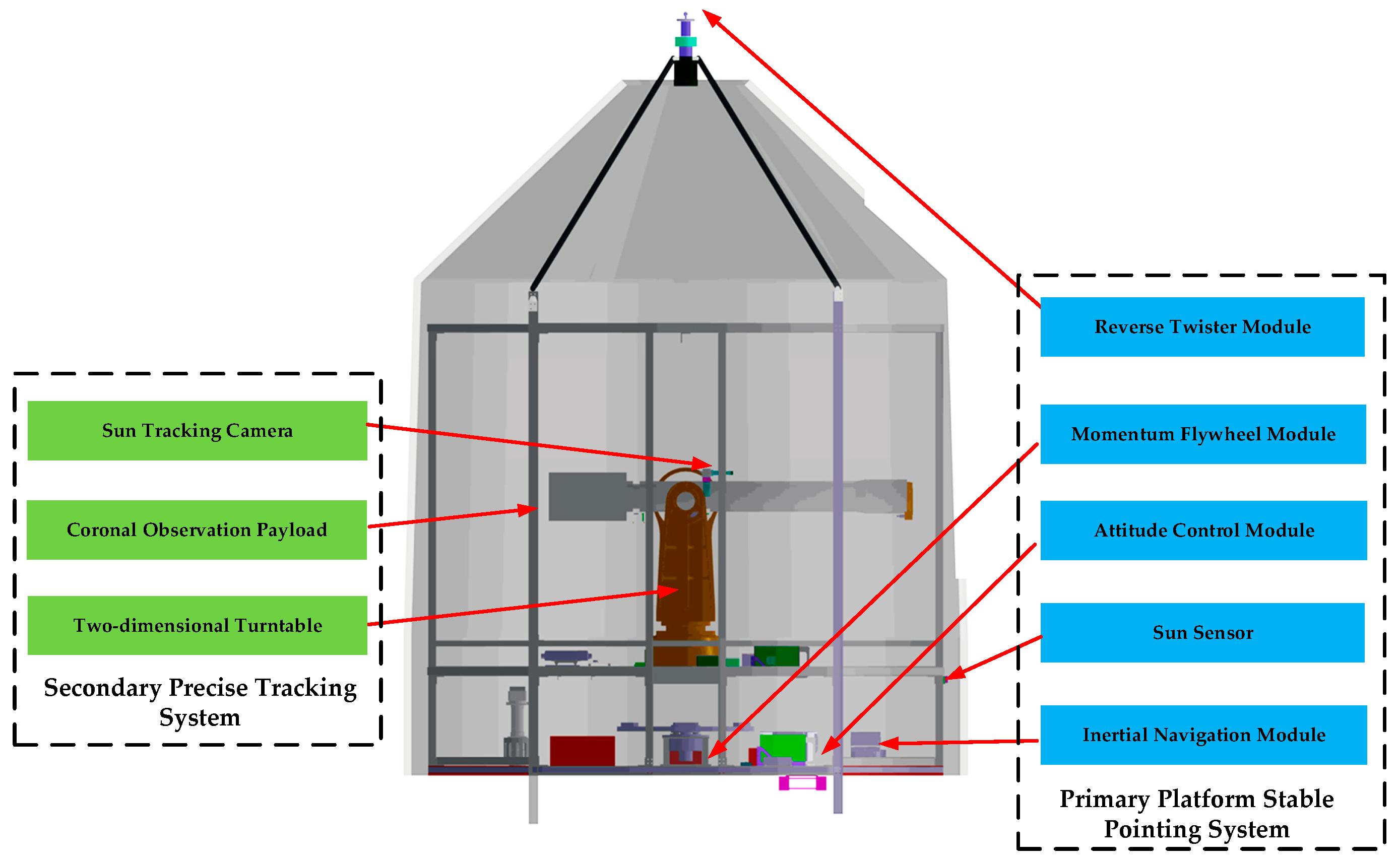
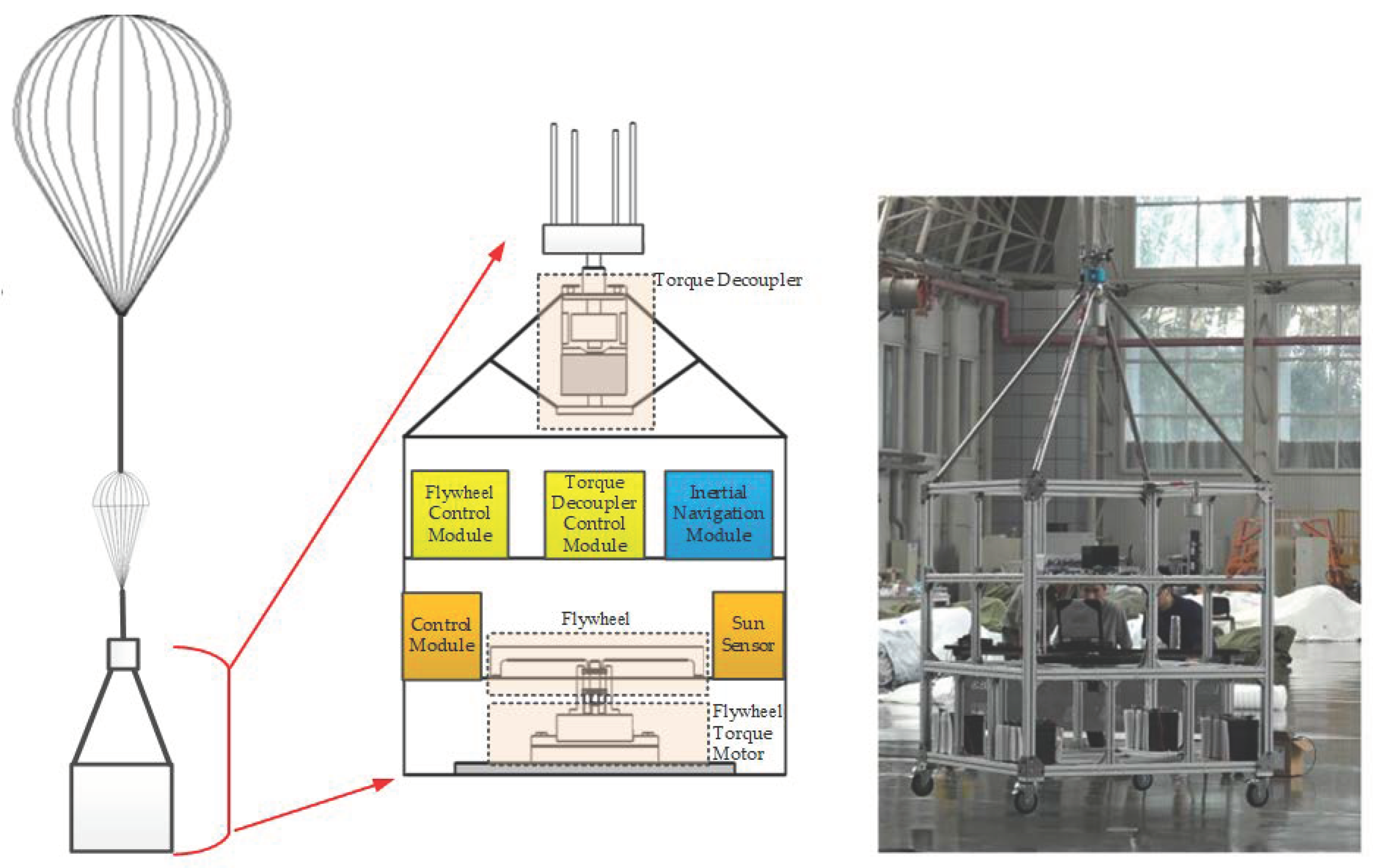
2.1. System Overview

The near-space-based coronal observation system mainly consists of a high-altitude balloon, a parachute, and an observation cabin, as shown in Figure 1. The high-altitude balloon uses a zero-pressure balloon, which is mainly composed of polyethylene material and charged with helium gas. The function of a parachute is to reduce the descent speed and protect the observation cabin. The observation platform is a key component of the entire system and includes a power supply system, fly control system, measurement and control system, stable pointing and tracking system, and payload control system.
This paper mostly focuses on the stable pointing and tracking system in a coronal observation system. The stable pointing and tracking system of the near-space spherical coronal observation platform includes two parts: the primary platform stable pointing system and the secondary precise tracking system, as shown in Figure 2. The primary platform stable pointing system is equipped with an inertial navigation module, including a gyroscope, a sun sensor, a set of actuators, and an attitude control module. The secondary precise tracking system consists of a high-precision two-dimensional turntable and a precision sun-tracking camera. The coronal observation payload is installed on the two-dimensional turntable, and the tracking camera is installed on the payload to ensure that the optical axis of the precision tracking camera and the optical observation equipment is parallel.
The collaborative workflow of the primary and secondary platforms in the stable pointing and tracking system is shown in Figure 3. The attitude control module on the primary platform drives the reaction momentum flywheel module and anti-twist module based on the information output by the sun sensor. With the support of high-precision inertial navigation and gyroscope data, the azimuth angle is stabilized within an error range of ±1° of the sun. After the primary platform rotates into place, the status signal is sent to the secondary platform. The high-precision two-dimensional turntable adopts a design of two axes and two frames, providing stable pointing functions for the azimuth and pitch angles of the optical payload. The two-dimensional turntable adjusts the azimuth and pitch angles based on the offset data output from the precision tracking camera, enabling precise pointing and tracking of the sun.

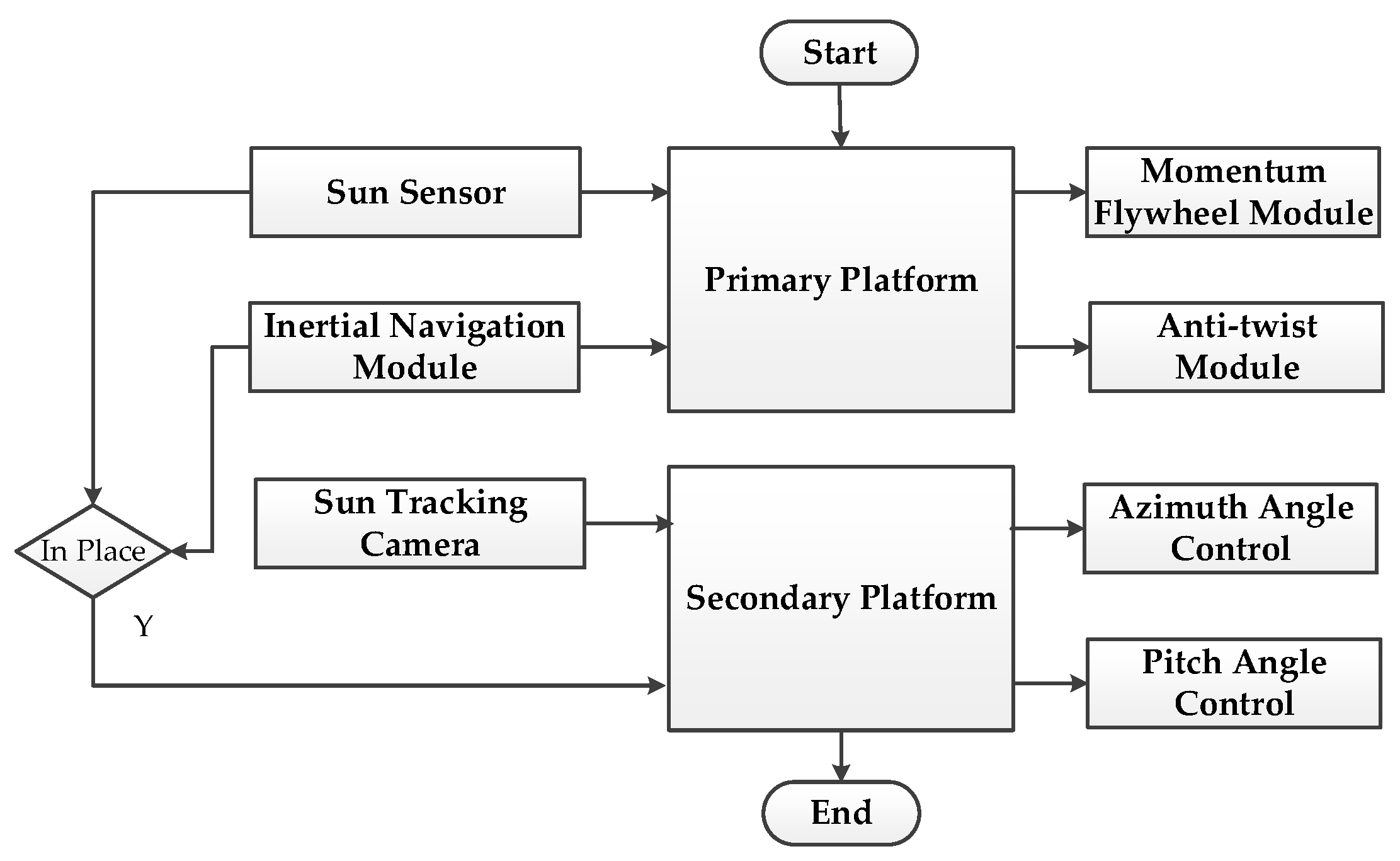
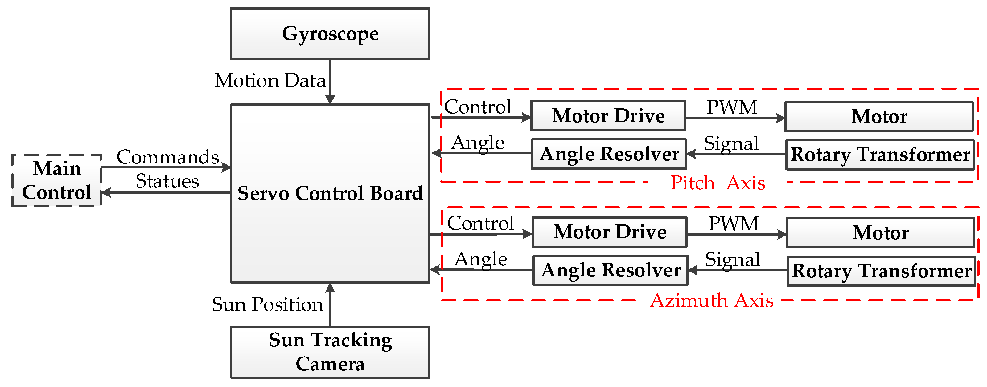
2.2. Primary Platform Stable Pointing System Design

Different from other spacecraft, the balloon-based observation platform carrying scientific research instruments is suspended below the balloon through a 10~100 m long sling and flexible structure, and it relies on the buoyancy of the balloon to achieve lift and high-altitude suspension flight. During the flat flight process, slight turbulence in the airflow will cause the balloon to experience varying wind pressures, resulting in a random force that causes the balloon to slowly rotate at a speed of approximately 0.01~0.1 revolutions per minute (rpm), which will cause changes in the orientation of the platform. Meanwhile, the long rope can cause the platform to undergo complex swinging movements, and due to the weak and stable airflow in the near space, the oscillation motion will gradually attenuate, and the average amplitude will eventually decrease to 0.01° at a stable state [31]. These disturbances must be suppressed otherwise they will cause an adverse impact on the accuracy of the attitude control of the system. The swing disturbance will directly change the attitude of the platform, thus affecting the pointing accuracy of the scientific instruments. The directional interference not only changes the posture of the platform but also influences the twisting and flexible structure of the lifting rope [32].
Therefore, in order to ensure the pointing accuracy of optical observation instruments towards the target, the observation platform needs to adjust the azimuth angle and ensure the stability of the azimuth angle. In order to eliminate the azimuth change caused by the periodic rotation of the balloon, this paper adopts a momentum flywheel. The acceleration or deceleration of the momentum flywheel can change its angular momentum, and the change in the flywheel’s angular momentum will enable the observation platform to obtain the control torque required to drive its rotation, achieving the purpose of azimuth control. In order to prevent reverse torque caused by the twisting of the lifting rope during the directional control of the observation platform and avoid saturation of the flywheel speed, a reverse-twisting device needs to be designed between the lifting rope and the observation platform to reduce the twisting effect. The primary platform stable pointing system is shown in Figure 4 and includes a flywheel, a flywheel torque motor, a torque decoupler, a flywheel control module, a torque decoupler control module, an inertial navigation module, a sun sensor, and a control module.
The simulation results show that when the pitch/roll attitude measurement accuracy is less than 0.05° and the azimuth attitude measurement accuracy is better than 0.2°, a stable pointing accuracy of ±1° can be achieved through the high-altitude balloon-based attitude adjustment mechanism using a momentum flywheel and torque decoupler device. This accuracy is high enough to provide a stable direction for the second platform.

2.3. Secondary Precise Tracking System

The secondary platform is used to load the coronagraph payload and perform solar observation tasks. It can point and stabilize the optical axis on a moving balloon and track the sun by moving in azimuth and pitch. The index of the secondary platform is shown in Table 2.

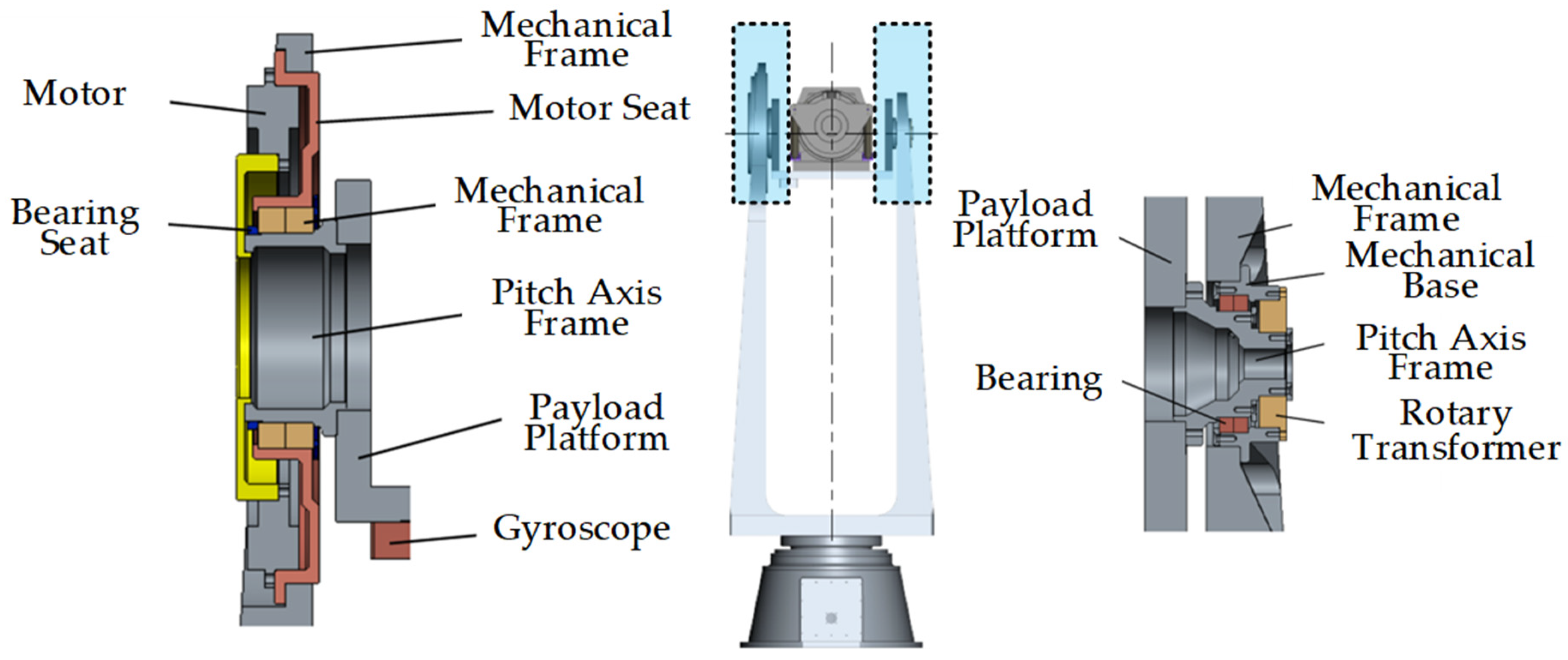
2.3.1. Mechanical Design

Due to the large size of the coronagraph, the secondary stable platform fully utilizes existing mature technologies and engineering experience to optimize design, reduce development costs and technical risks, and shorten development cycles. It adopts modular, standardized, programmable, and interchangeable design technologies to facilitate product maintenance and upgrading. It also adopts derating design, redundancy design, and margin design to ensure product reliability and environmental adaptability. The overall mechanical design of the secondary stable platform is shown in Figure 5. The height of the platform is more than 1400 mm, and the length of the platform is about 1900 mm. The mechanical limit of the azimuth angle is set from −172° to +172°, and the pitch angle is set from −5° to +85°. The electrical limit of azimuth angle is set from −160° to +160°, and the pitch angle is set from +5° to +78°.
The azimuth axis system is composed of an azimuth frame, an azimuth motor, bearings, and a rotary transformer, as shown in Figure 6. The azimuth motor directly drives the azimuth axis frame to rotate, and the azimuth axis frame is connected to the mechanical frame rigidly. The azimuth rotary transformer is connected to the mechanical base plate and the azimuth axis frame to achieve azimuth angle measurement. The servo control board, motor drive board, and power board are installed on the base frame, with a removable cover on the frame side, making it easy to maintain the circuit boards.
The pitch frame is used to install the coronagraph, and it mainly consists of a pitch frame, a pitch motor, bearings, a gyroscope, and a rotary transformer, as shown in Figure 7. The pitch motor and rotary transformer are located on a different side of the mechanical frame for weight balancing. The gyroscope is installed on the pitch frame and directly measures the angle change of the coronagraph. To minimize system weight, the gravity center of the coronagraph system should be as close as possible to the pitch axis.

2.3.2. Stable Pointing and Tracking Design

The stable pointing and tracking function of the platform is realized by a combination of servo control, motor drive, motion measurement, angle measurement, and sun position measurement, as shown in Figure 8. The servo control board receives instructions from the upper computer and executes them, returning status information, such as current angle position, receives gyro signals and sun position information, and drives the azimuth and pitch motors using PWM (Pulse Width Modulation) to keep stable and track the sun.
The motion speed of the balloon-based platform is very low, and the disturbance frequency is low. A MEMS gyroscope was selected as an angular rate sensor with reliable quality and stable accuracy as performance indicators. The rotary transformer in this paper has good stability and adaptability and can achieve a measurement accuracy of 20″.
In order to achieve various working states of the secondary platform and meet the requirements of the coronagraph observation function, there are 3 control states: the stable control state, the locking control state, and the tracking control state.

2.3.3. Accuracy Analysis

Tracking accuracy refers to the deviation in the line of sight of a target with certain motion characteristics that reflects the stable tracking of the platform. Tracking accuracy mainly depends on the reliability of the servo control system and tracking algorithm.
The servo control factors that affect tracking accuracy mainly include the tracking loop correction algorithm and the stability loop. The main evaluation indicators of the tracking loop correction algorithm are bandwidth and static error. The wider the tracking loop bandwidth, the better the stable performance, and the smaller the static error, the better the tracking performance [33].
At present, the volume and weight of this system are relatively large, and the interference torque of the shaft system is controlled below 0.5 N∙m. The gyroscope noise is controlled below 7°/h (the gyroscope noise index is 5°/h, and according to experience, the noise may be increased due to power supply noise, reading noise, etc.). The oscillation frequency and amplitude of the balloon are very low (the balloon is unpowered, the high-altitude wind direction and wind speed are fixed, and the oscillation frequency and amplitude of the balloon are not high). According to the response curve of the stable circuit to the interference torque (0.5 N∙m, 1°, 0.1 Hz), the peak stability accuracy is 23 μrad, and the root mean square value is 9 μrad, which can meet the accuracy of ≤25 μrad, providing a guarantee for improving tracking accuracy.
The purpose of an automatic tracking loop is to ensure the framework to track targets within a certain speed and acceleration range and achieve the required steady-state and dynamic performance. The main factors affecting the steady-state and dynamic performance are the bandwidth and open-loop gain of the tracking loop system.
The image tracker can be regarded as a sampling and holding stage, where the tracker outputs an error signal once per frame and holds it for one frame, with a sampling frequency equivalent to a frame rate of 80 Hz. Due to the 12.5 ms delay in each error signal output of the image tracker and the error signal containing a certain high-frequency component, the tracking loop is usually calibrated to an I-type system to improve the stability of the system and achieve better tracking results.
Considering the impact of the interference torque caused by balloon oscillation, under the interference torque of frequency of 0.1 Hz, amplitude of 1°, and 0.5 N∙m, the target motion speed is input under conditions such as 4′/s (Earth’s rotation speed; the sun is basically stationary), and the tracking accuracy simulation result is 0.02 mrad, about 4″, which can realize the 10″ tracking accuracy.

3. Results

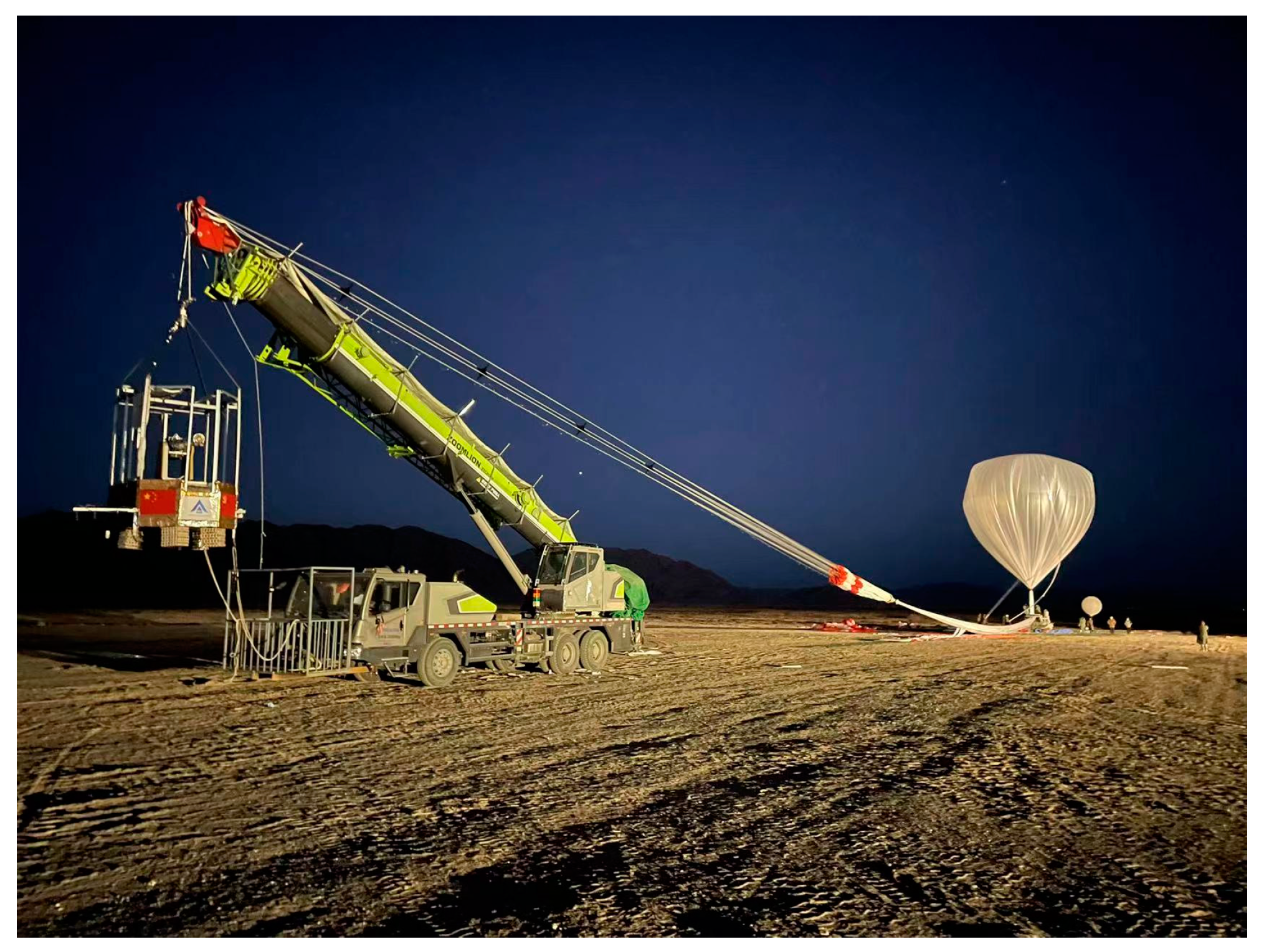
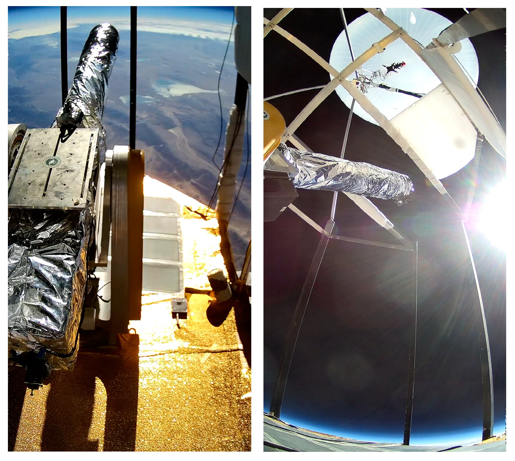
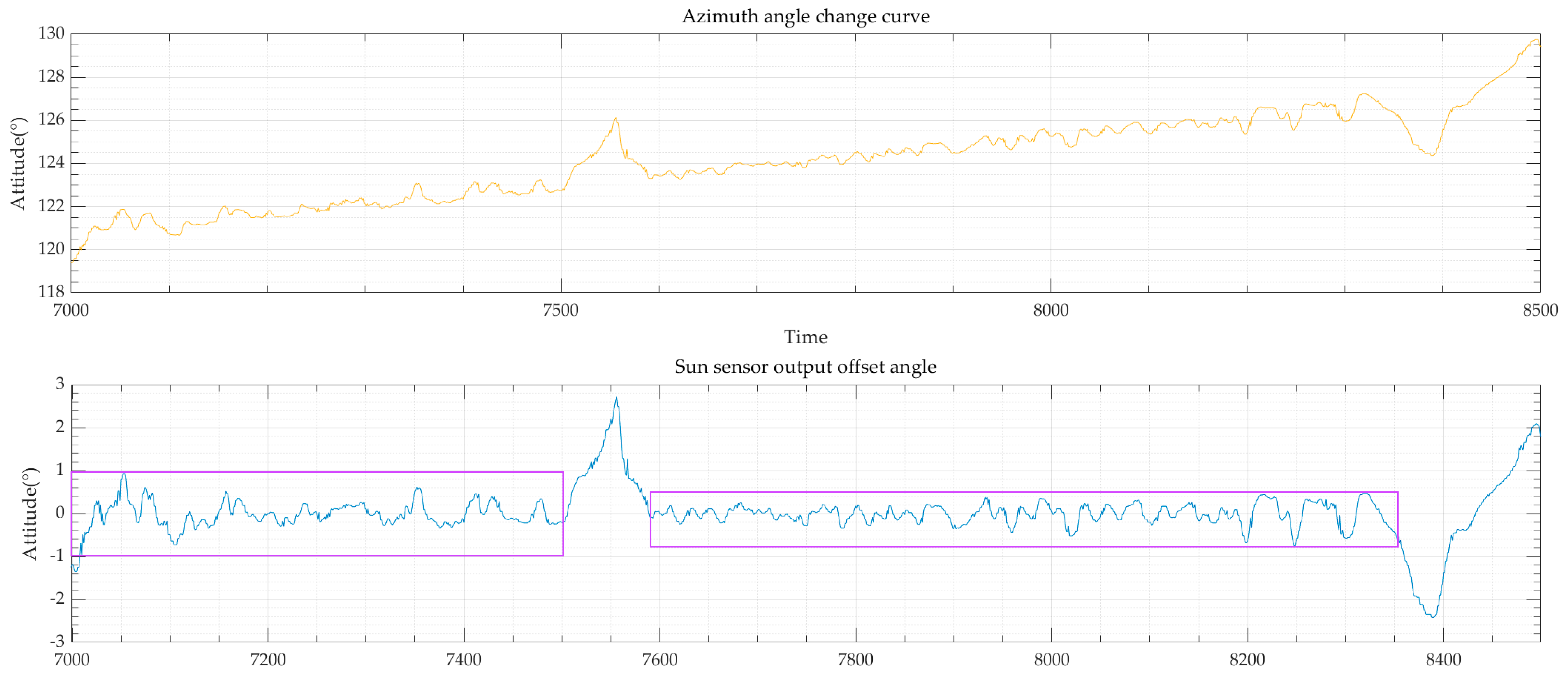
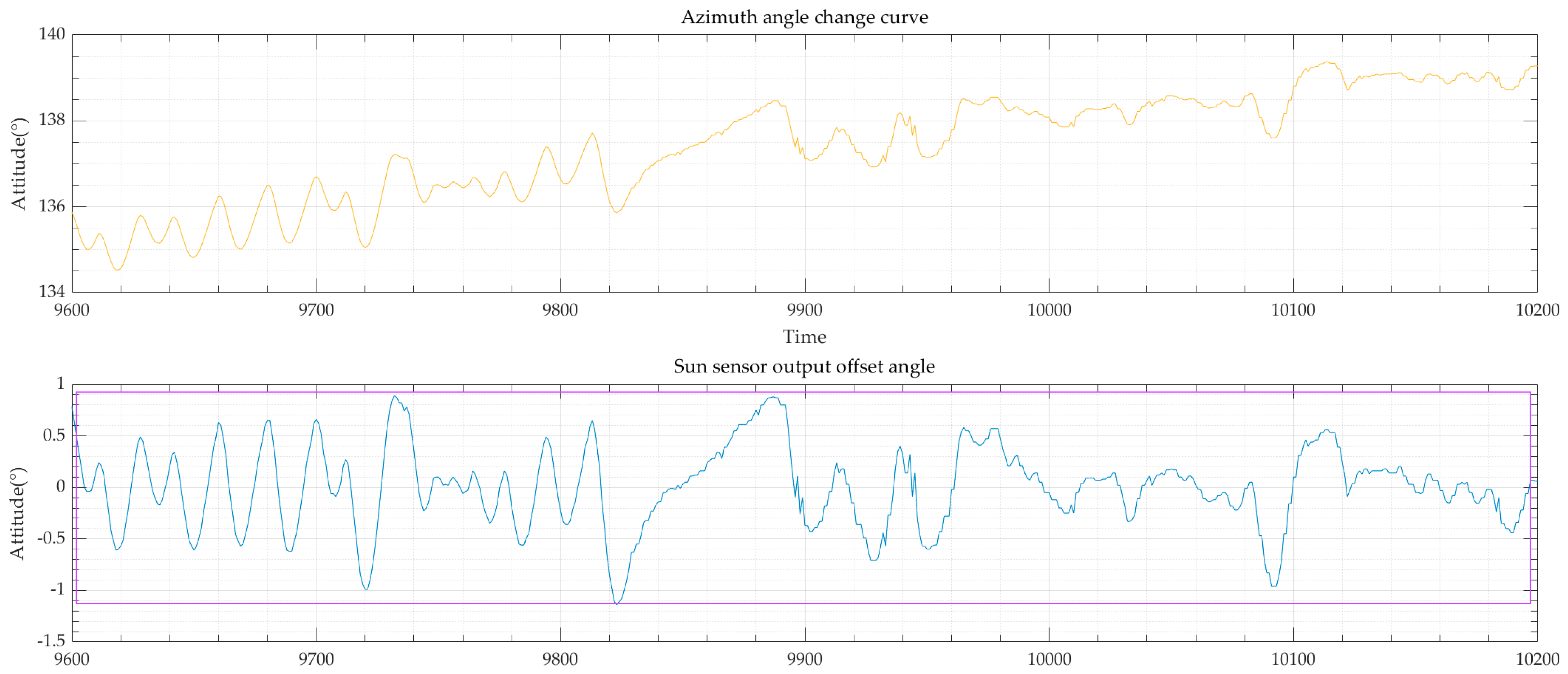
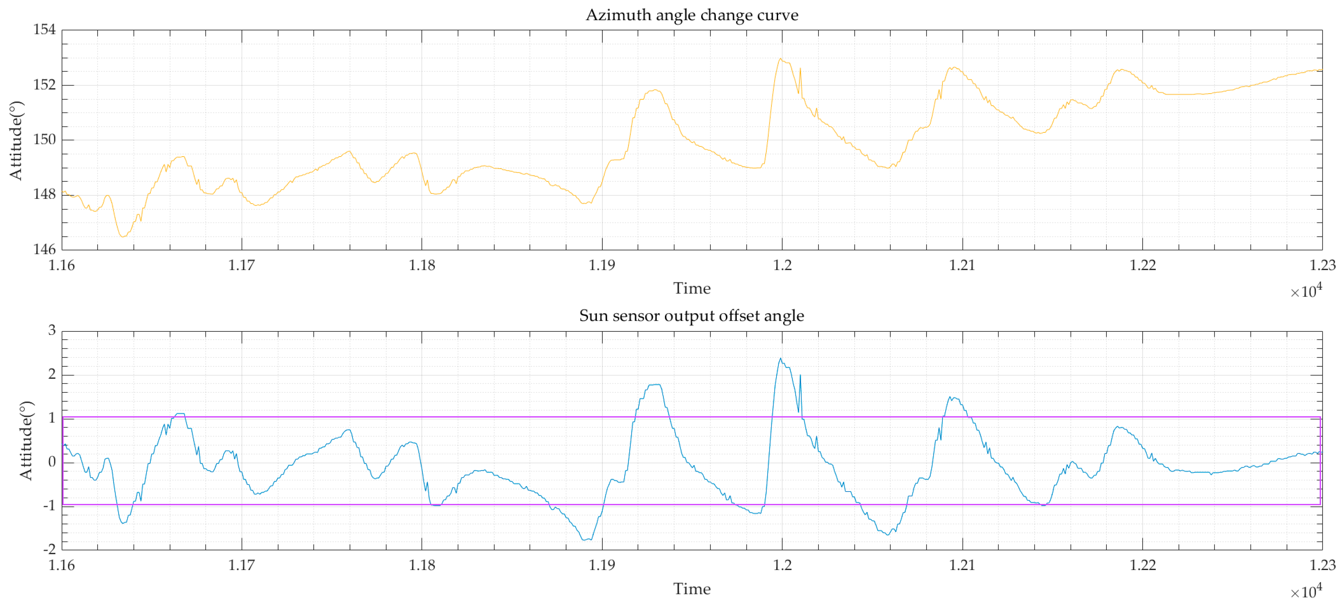
3.1. Flight Experiment Result

On 4 October 2022, a near-space high-altitude-based coronagraph flight experiment was conducted in the Dachaidan District, Qinghai Province, China. This experiment started in the morning, and the balloon was launched at 8:54. The entire experiment system before the balloon was launched is shown in Figure 9. The balloon reached an altitude of 30 km and began flat flying at 9:26. The coronagraph began to work, and the status of the observation platform during the flight after a total flight time of 6 h and 32 min, including a flight of 4 h and 50 min above 29 km, is shown in Figure 10. The platform landed at 15:26, and the landing status is shown in Figure 11. After the experiment, the security control cabin, payload cabin, scientific payload, and experimental data were all recovered in good condition.

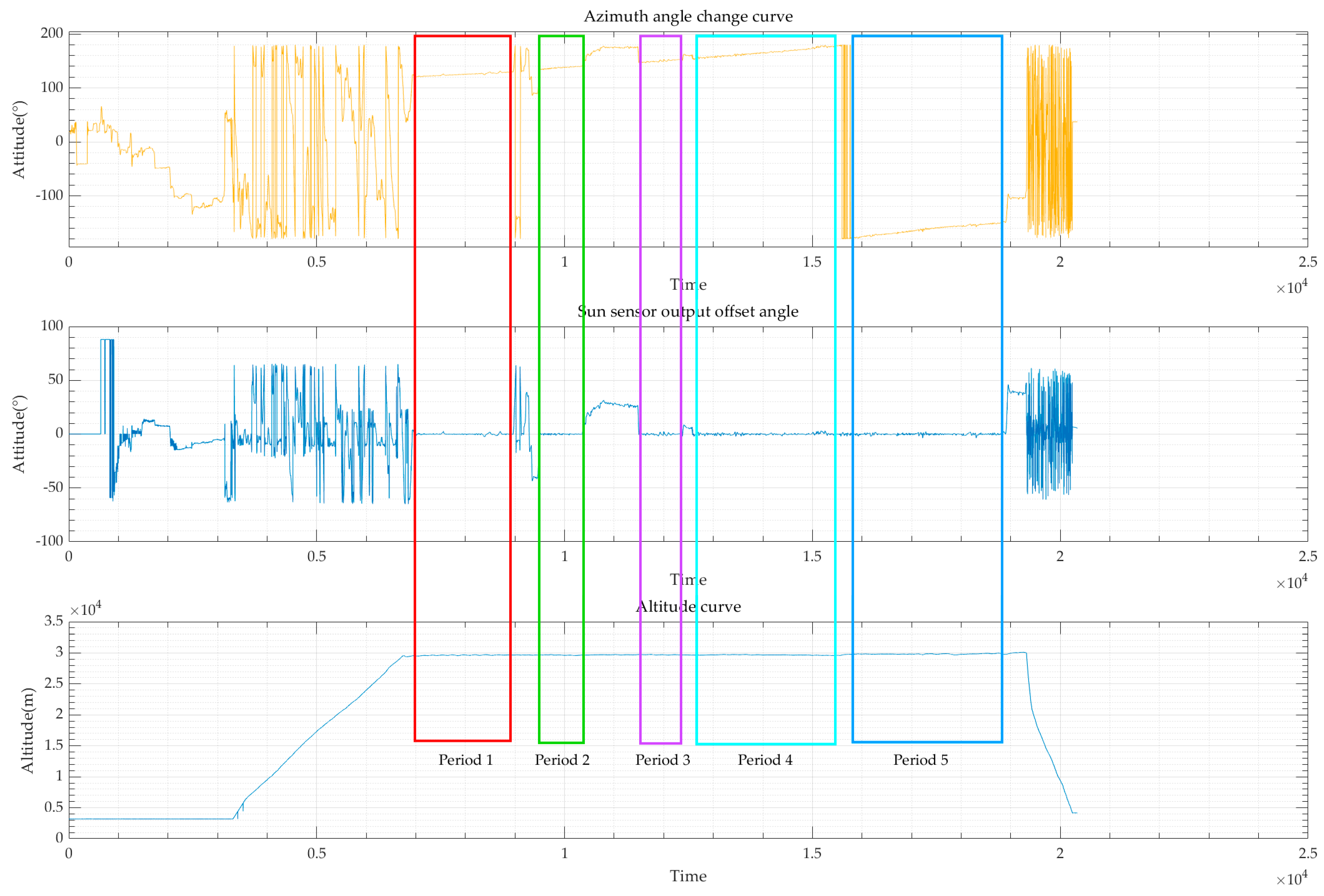
3.2. Flight Result Analysis

The azimuth curve of the primary platform, the offset angle relative to the sun of the sun sensor output, and the height change curve recorded by the spherical observation platform in this observation experiment are shown in Figure 12. The spherical coronagraph observation system conducted a total of five observation periods, as shown in the time periods 1 to 5, with different color rectangles.
Based on the observation of period 1, the azimuth angle of the primary platform and the deviation angle of the solar sensor during that period were analyzed, as shown in Figure 13. It can be seen that during this observation period, the orientation of the primary platform can reach or even exceed ±1°, reaching −0.8–0.6°, as shown in the purple box.
The result of period 2 is shown in Figure 14. In this observation period, the primary platform pointing system can realize ±1° pointing accuracy most of the time, while the whole accuracy is −1.1 to 0.9°, as shown in the purple box.
The result of period 3 is shown in Figure 15. In this observation period, the primary platform pointing system can realize ±1° pointing accuracy most of the time, while the whole accuracy is −1.8° to 2.4°, as shown in the purple box.
The result of period 4 is shown in Figure 16. In this observation period, the primary platform pointing system can realize ±1° pointing accuracy most of the time, while the whole accuracy is −2° to 2.5°, as shown in the purple box.
The result of period 5 is shown in Figure 17. In this observation period, the primary platform pointing system can realize ±1° pointing accuracy most of the time, while the whole accuracy is −3.5° to 2.5° as shown in the purple box.
The secondary precise tracking system also worked well during the experiment, and it ensured the coronagraph obtained more than 20,000 images. Another group in our team will analyze the obtained observation data as soon as possible and share it with our counterparts in the future.

4. Conclusions

In this experiment, the primary platform pointing system and secondary precise tracking system on the balloon-based observation platform worked normally, providing a guarantee for the coronagraph’s stable tracking and detection of the sun. The primary platform pointing system can realize ±1° pointing accuracy. However, some other issues were also exposed in this experiment. Firstly, the experimental platform did not store real-time position and attitude information of the secondary precise tracking system, and it is currently unable to analyze its specific angle, attitude, and other information in this experiment. In subsequent works, we will upgrade and optimize the whole system. Firstly, we will improve the storage of real-time angles, attitudes, and other information. Secondly, we will further improve the performance of pointing and tracking accuracy to provide support for the coronagraph to obtain better imaging quality images. In addition, the next flight experiment is planned to be conducted in 2024 or 2025. Before conducting the flight experiment, we will perform multiple ground observation experiments to verify the overall performance of the system.

Author Contributions

Conceptualization, M.H.; methodology, L.Q.; resources, W.Z.; writing—original draft preparation, Z.W. and Z.Z.; writing—review and editing, Y.S. and G.W.; visualization, X.L. and Y.Z.; project administration, M.H. All authors have read and agreed to the published version of the manuscript.

Funding

This research was funded by the strategic priority research program of the Chinese Academy of Science (Grant No: XDA17020603), the Space Debris Research Project (KJSP2020020201), and the Youth Innovation Promotion Association CAS.

Data Availability Statement

The original contributions presented in the study are included in the article. Further inquiries can be directed to the corresponding author.

Conflicts of Interest

The authors declare no conflicts of interest.

References

  1. Wang, W.-Q. Near-space vehicles: Supply a gap between satellites and airplanes for remote sensing. IEEE Aerosp. Electron. Syst. Mag. 2011, 26, 4–9. [Google Scholar] [CrossRef]
  2. Azadi, M.; Popov, G.A.; Lu, Z.; Eskenazi, A.G.; Bang, A.J.W.; Campbell, M.F.; Hu, H.; Bargatin, I. Controlled levitation of nanostructured thin films for sun-powered near-space flight. Sci. Adv. 2021, 7, eabe1127. [Google Scholar] [CrossRef] [PubMed]
  3. Wang, Z.; Huang, M.; Qian, L.; Zhao, B.; Wang, G. High-Altitude Balloon-Based Sensor System Design and Implementation. Sensors 2020, 20, 2080. [Google Scholar] [CrossRef] [PubMed]
  4. Sun, G.; Li, M.; Wang, Y.; Zhou, K.; Hu, X.; Guo, Z.; Zhu, L. Temperature-compensated fiber-optic online monitoring methodology for 3D shape and strain of near-space airship envelope. Appl. Opt. 2022, 61, 9279–9295. [Google Scholar] [CrossRef] [PubMed]
  5. Rhodes, J.; Dobke, B.; Booth, J.; Massey, R.; Liewer, K.; Smith, R.; Amara, A.; Aldrich, J.; Berge, J.; Bezawada, N.; et al. Space-quality data from balloon-borne telescopes: The High Altitude Lensing Observatory (HALO). Astropart. Phys. 2012, 38, 31–40. [Google Scholar] [CrossRef]
  6. Tucker, G.S.; Ade, P.A.; Bock, J.J.; Devlin, M.; Griffin, M.; Gundersen, J.; Gundersen, J.; Halpern, M.; Hargrave, P.; Hughes, D.; et al. The balloon-borne large aperture sub-millimeter telescope. Adv. Space Res. 2004, 33, 1793–1796. [Google Scholar] [CrossRef]
  7. Cathey, H.M. Development overview of the revised NASA Ultra Long Duration Balloon. Adv. Space Res. 2008, 42, 1624–1632. [Google Scholar] [CrossRef]
  8. Gunderson, K.S.; Chen, C.H.; Christensen, F.E.; Craig, W.W.; Decker, T.A.; Hailey, C.J.; Harrison, F.A.; McLean, R.; Wurtz, R.E.; Ziock, K. Ground performance of the High-Energy Focusing Telescope (HEFT) attitude control system. Proc. Spie Int. Soc. Opt. Eng. 2004, 5165, 158–168. [Google Scholar]
  9. Kremic, T.; Cheng, A.F.; Hibbitts, K.; Young, E.F.; Ansari, R.R.; Dolloff, M.D.; Landis, R.R. Stratospheric balloons for planetary science and the Balloon Observation Platform for Planetary Science (BOPPS) mission summary. In Proceedings of the 2015 IEEE Aerospace Conference, Big Sky, MT, USA, 7–14 March 2015. [Google Scholar]
  10. Stambaugh, K.; Bernasconi, P.; Bauer, B. Using the BOPPS balloon mission as a tool to provide engineers with end-to-end mission development experience. In Proceedings of the AIAA SPACE 2015 Conference and Exposition, Pasadena, CA, USA, 31 August–2 September 2015. [Google Scholar]
  11. Diller, J.; Dinkel, K.; Dischner, Z.; Young, E. Design and performance of the BOPPS UVVis fine pointing system. In Proceedings of the 2015 IEEE Aerospace Conference, Big Sky, MT, USA, 7–14 March 2015. [Google Scholar]
  12. Lewis, M.; Juergens, J.; Aretskin-Hariton, E.; Woodruff, R. Image guider subsystem analysis for the GHAPS project. In Proceedings of the Ground-Based and Airborne Instrumentation for Astronomy VII, Austin, TX, USA, 10–14 June 2018. [Google Scholar]
  13. Catanzaro, B.E.; Pham, T.; Olmi, L.; Martinson, K.E.; Devlin, M. Design and fabrication of a lightweight 2-m telescope for the balloon-borne large-aperture submillimeter telescope: BLAST. Proc. SPIE Int. Soc. Opt. Eng. 2002, 4818, 71–78. [Google Scholar]
  14. Wiebe, D.V. BLAST: A Balloon-Borne, Large-Aperture, Submillimetre Telescope; University of Toronto: Toronto, ON, Canada, 2008. [Google Scholar]
  15. Pascale, E. The Balloon-borne Large Aperture Submillimetre Telescope (BLAST) and BLASTPol. Proc. Int. Astron. Union 2012, 8, 154–160. [Google Scholar] [CrossRef]
  16. Lorenzo, M. BLAST: Studying Cosmic and Galactic Star Formation from a Stratospheric Balloon. Ph.D. Thesis, Cardiff University, Cardiff, UK, 2011. [Google Scholar]
  17. Pascale, E.; Ade, P.A.R.; Angilè, F.E.; Benton, S.J.; Devlin, M.J.; Dober, B.; Fissel, L.M.; Fukui, Y.; Gandilo, N.N.; Gundersen, J.O.; et al. The balloon-borne large-aperture submillimeter telescope for polarimetry-BLASTPol: Performance and results from the 2010 Antarctic flight: Proc. SPIE. In Proceedings of the Ground-Based and Airborne Telescopes IV, Amsterdam, The Netherlands, 27 September 2012. [Google Scholar]
  18. Soler, P.J.; Ade, P.A.; Angile, F.E.; Benton, S.J.; Devlin, M.J.; Dober, B.; Fissel, L.M.; Fukui, Y.; Galitzki, N.; Klein, J.; et al. Thermal design and performance of the balloon-borne large aperture submillimeter telescope for polarimetry BLASTPol: Proc. SPIE. In Proceedings of the Ground-based and Airborne Telescopes V, Montréal, QC, Canada, 22 July 2014. [Google Scholar]
  19. Lourie, N.P.; Ade, P.A.R.; Angile, F.E.; Ashton, P.C.; Austermann, J.E.; Devlin, M.J.; Dober, B.; Galitzki, N.; Gao, J.; Gordon, S.; et al. Preflight characterization of the BLAST-TNG receiver and detector arrays. In Proceedings of the SPIE 10708, Millimeter, Submillimeter, and Far-Infrared Detectors and Instrumentation for Astronomy IX, Austin, TX, USA, 10–15 June 2018. [Google Scholar]
  20. Galitzki, N. Magnetic Fields in Molecular Clouds: The BLASTPol and BLAST-TNG Experiment; University of Pennsylvania: Pennsylvania, PA, USA, 2016. [Google Scholar]
  21. Cocco, G.D.; Basili, A.; Franceschini, T.; Landini, G.; Malaguti, G.; Palladino, G.; Silvestri, S.; Gizzi, L.A.; Barbini, A.; Galimberti, M. HiPeG: A high performance balloon gondola for fine angular resolution X-ray telescopes. Adv. Space Res. 2006, 37, 2103–2107. [Google Scholar] [CrossRef]
  22. Barthol, P.; Gandorfer, A.; Solanki, S.K.; Schüssler, M.; Chares, B.; Curdt, W.; Deutsch, W.; Feller, A.; Germerott, D.; Grauf, B.; et al. The Sunrise Mission. Sol. Phys. 2011, 268, 1–34. [Google Scholar] [CrossRef]
  23. Walker, C.K.; Kulesa, C.A.; Groppi, C.E. The Stratospheric Terahertz Observatory (STO): An LDB Experiment to Investigate the Life Cycle of the Interstellar Medium. In Proceedings of the 19th International Symposium on Space Terahertz Technology, Groningen, The Netherlands, 28–30 April 2008; Volume 28, p. 32. [Google Scholar]
  24. Chauvin, M.; Friis, M.; Jackson, M.; Kawano, T.; Kiss, M.; Mikhalev, V.; Ohashi, N.; Stana, T.; Takahashi, H.; Pearce, M. Calibration and performance studies of the balloon-borne hard X-ray polarimeter PoGO+. Nucl. Instrum. Methods Phys. Res. 2017, 859, 125–133. [Google Scholar] [CrossRef]
  25. Christian, L. The Stratospheric Balloon Mission PoGO+ from Esrange to Victoria Island. In Proceedings of the AIAA Balloon Systems Conference, Denver, CO, USA, 5–9 June 2017. [Google Scholar]
  26. He, F. Remote Sensing of planetary space environment. Chin. Sci. Bull. 2020, 65, 1305–1319. (In Chinese) [Google Scholar] [CrossRef]
  27. Wang, Z.; Huang, M.; Sun, Y.; Tao, T.; Qian, L.; Zhang, G.; Zhao, B.; Han, W.; Wang, G.; Zhao, Y. Near-Earth space balloon-based multi-band airglow imager optic design. Appl. Opt. 2021, 60, 8057–8068. [Google Scholar] [CrossRef] [PubMed]
  28. Jun, L.; TengFei, S.; MingZhe, S.; Tao, Z.; FangYu, X.; JingXing, W.; Yu, F.; Yan, L.; KaiFeng, K.; Min, H.; et al. A 50-mm balloon-borne white-light coronagraph: I.Basic structure and experiments on the ground. Sci. Sin. Phys. Mech. Astron. 2023, 53, 259611. [Google Scholar] [CrossRef]
  29. Wei, F.; Zhang, X.; Peng, S.; Li, W.; Li, C.; Leng, S.; Feng, P. Solar FUV/UV Spectrometer Onboard High Altitude Balloon Flight in the Near Space. Acta Photonica Sin. 2021, 50, 1222002. [Google Scholar]
  30. Chen, Z.; Li, R.; Sun, X.; Yang, K.; Wang, B.; Bai, Y.; Wang, L. Control system of intensified ultraviolet spectrometer in near space, Proc. SPIE 12254. In Proceedings of the International Conference on Electronic Information Technology (EIT 2022), 122542M, Chengdu, China, 23 May 2022. [Google Scholar] [CrossRef]
  31. Yajima, N.; Kokaji, S.; Hashino, S. Report of Mechanical Engineering Laboratory No.135; ISAS: Sagamihara, Japan, 1986. [Google Scholar]
  32. Gruner, T.D.; Olney, D.J.; Russo, A.M. Measurements of Load Train Motion on a Stratospheric Balloon Flight; NASA Goddard Space Flight Center: Greenbelt, MD, USA, 2005. [Google Scholar]
  33. Zlotnik, D.; Forbes, J. Dynamic modelling, estimation, and control for precision pointing of an atmospheric balloon platform. Trans. Can. Soc. Mech. Eng. 2014, 38, 263–274. [Google Scholar] [CrossRef]
Figure 1. Near-space-based coronal observation system.
Applsci 14 06531 g001
Figure 2. Diagram of the stable pointing and tracking system.
Applsci 14 06531 g002
Figure 3. Workflow of the stable pointing and tracking system.
Applsci 14 06531 g003
Figure 4. Diagram of primary platform stable pointing system.
Applsci 14 06531 g004
Figure 5. Overall mechanical design of the secondary stable platform.
Applsci 14 06531 g005
Figure 6. Diagram of the azimuth axis system.
Applsci 14 06531 g006
Figure 7. Diagram of the pitch axis system.
Applsci 14 06531 g007
Figure 8. Diagram of the stable pointing and tracking function.
Applsci 14 06531 g008
Figure 9. The entire experiment system before the balloon was launched.
Applsci 14 06531 g009
Figure 10. The status of the observation platform during the flight.
Applsci 14 06531 g010
Figure 11. The landing status of the platform after the flight.
Applsci 14 06531 g011
Figure 12. Coronagraph observation platform data during this flight.
Applsci 14 06531 g012
Figure 13. Azimuth and sun offset-angle curve of period 1.
Applsci 14 06531 g013
Figure 14. Azimuth and sun offset-angle curve of period 2.
Applsci 14 06531 g014
Figure 15. Azimuth and sun offset-angle curve of period 3.
Applsci 14 06531 g015
Figure 16. Azimuth and sun offset-angle curve of period 4.
Applsci 14 06531 g016
Figure 17. Azimuth and sun offset-angle curve of period 5.
Applsci 14 06531 g017
Table 1. Near-space balloon-based optical detection experiments.
TimeCountryNameIndex
2005The United StatesBLAST40 km
2005ItalyHiPeG10″
2009Germany and the United StatesSunrise35 km to 37 km, 7.5″
2010The United StatesSTO35 km, 1″
2016SwedenPOGO0.01°
Table 2. Index of the secondary platform.
ParameterIndex
Horizon pointing rangeAzimuth: −160° to +160°
Pitch: +5° to +78°
Search angular velocity≥3°/s
Search angular acceleration≥3°/s2
Tracking accuracy≤10″
Precision tracking cameraImage size: 1600 × 1200
Maximum frame rate: 80 fps
Measurement accuracy: 1″
Disclaimer/Publisher’s Note: The statements, opinions and data contained in all publications are solely those of the individual author(s) and contributor(s) and not of MDPI and/or the editor(s). MDPI and/or the editor(s) disclaim responsibility for any injury to people or property resulting from any ideas, methods, instructions or products referred to in the content.

