Review

A Review of Foot–Terrain Interaction Mechanics for Heavy-Duty Legged Robots

1
School of Mechanical Engineering, Tianjin University of Technology and Education, Tianjin 300222, China
2
School of Information Technology Engineering, Tianjin University of Technology and Education, Tianjin 300222, China
3
State Key Laboratory of Robotics and Systems, Harbin Institute of Technology, Harbin 150001, China
4
School of Automotive Engineering, Harbin Institute of Technology (Weihai), Weihai 264209, China
5
Tianjin Institute of Aerospace Mechanical and Electrical Equipment, Tianjin 300458, China
*
Author to whom correspondence should be addressed.
Appl. Sci. 2024, 14(15), 6541; https://doi.org/10.3390/app14156541
Submission received: 29 May 2024 / Revised: 16 July 2024 / Accepted: 24 July 2024 / Published: 26 July 2024
(This article belongs to the Special Issue Trajectory Analysis, Positioning and Control of Mobile Robots)

Abstract

:
Heavy-duty legged robots have played an important role in material transportation, planet exploration, and other fields due to their unique advantages in complex and harsh terrain environments. The instability phenomenon of the heavy-duty legged robots often arises during the dynamic interactions between the supporting feet and the intricate terrains, which significantly impact the ability of the heavy-duty legged robots to move rapidly and accomplish tasks. Therefore, it is necessary to assess the mechanical behavior of foot–terrain interactions for the heavy-duty legged robots. In order to achieve the above goal, a systematic literature review methodology is employed to examine recent technical scientific publications, aiming to identify both current and prospective research fields. The characteristics of supporting feet for different heavy-duty legged robots are compared and analyzed. The foot–terrain mechanical models of the heavy-duty legged robots are discussed. The problems that need further research are summarized and presented, which is conducive to further deepening and expanding the research on the mechanical behavior of foot–terrain interactions for heavy-duty legged robots.

1. Introduction

In nature, there are various uneven and irregular terrains that have complex environmental surfaces, such as grassland, desert, mud pools, and mountains. The exploration of unknown terrain is dangerous for humans. Autonomous mobile robots can be the first to enter the detection before humans enter unfamiliar and dangerous environments, which greatly ensures the safety of human life and improves the efficiency of exploration work. With the continuous development of autonomous mobile robot technology, autonomous mobile robots have been widely used in multiple fields to protect human safety and improve production efficiency [1].
Considering the varying modes of contact between mobile robots and terrain, the broad classification of mobile robots includes wheeled robots, tracked robots, snake-like robots, spherical robots, and legged robots [2]. The currently widely researched and applied mobile robots are mainly wheeled robots. Wheeled robots have limitations in their use due to their high requirements for terrain environments, necessitating relatively wide, flat, or smaller rugged terrains. Compared to the harsh requirements of wheeled robots in the terrain environment, tracked robots have to some extent improved the high demand for the terrain. However, the large contact area of the tracks with the terrain also brings new problems. The terrain adaptability of snake robots has significantly improved compared to the tracked robots, but these types of robots lack a load-bearing capacity and have relatively slow movement speed. They can only achieve the robot’s own motion [3]. The spherical robots have good mobility performance. Although the spherical shape can effectively protect the fragile and moving parts of the robots from external damage, the contact mode between the spherical robots and the terrain is point contact, which is not conducive to control movement. The spherical robots have not been widely used [4]. The legged robots often use biomimetic technology to design their structures. They usually imitate humans walking on two legs, and mammals or insects walking on multiple legs. Their structures are more flexible and can maintain relative stability. Compared to wheeled robots and tracked robots, legged robots require only intermittent and discrete landing points to cross obstacles like legged animals. Therefore, walking mechanisms have stronger adaptability to walk on complex terrain. Compared to snake robots and spherical robots, the legged robots have a load-bearing capacity. The research on legged robots has received widespread attention in recent years due to their excellent terrain adaptability and motion flexibility. In fields such as interstellar exploration [5], humanitarian demining [6], logging [7], and nuclear industry [8], the legged robots have unique advantages and have been widely used.
Based on their load-bearing abilities, legged robots can be classified into two categories: heavy-duty legged robots and light-duty legged robots. It can be seen that heavy-duty legged robots have three characteristics compared to light-duty legged robots: large mass, large volume, and high payload–total mass ratio [1]. The heavy-duty legged robots may encounter various complex terrains in actual environments, which also makes the robots full of challenges when moving. Compared to the light-duty legged robots, the heavy-duty legged robots are more prone to foot sinkage occurring when traveling in soft and muddy terrains due to the lower pressure-bearing capacity of the soil. With the low adhesion of smooth surfaces such as ice and snow, heavy-duty legged robots are also more prone to foot slips occurring. The heavy-duty legged robots are more sensitive to foot–terrain interactions compared to the light-duty legged robots. When a heavy-duty legged robot interacts dynamically with complex terrain during movement, it is prone to the phenomenon of robot instability. It has a significant impact on achieving rapid robot movement and completing designated tasks. Studying the foot–terrain mechanical behavior of the heavy-duty legged robots and establishing an appropriate foot–terrain mechanical model are meaningful. The reasonable landing area of the heavy-duty legged robots is increased. The optimization of control strategies is achieved. The parameters selection of foot structure design is facilitated. By designing foot configurations for different working conditions, the mobility performance of the heavy-duty legged robots is improved. The area of some irregular feet in contact with the terrain is not equal to the overall size of the feet. An accurate area is essential in model design.
Compared to the light-duty legged robots, the heavy-duty legged robots have a larger leg mass. Both the supporting and the swinging legs can withstand greater torque during the movement, and that puts forward better technical requirements for maintaining the stability of the robots. Thus, it is particularly important to study the mechanical behavior of foot–terrain interactions of the heavy-duty legged robots. The forces acting on the robot’s feet are divided into normal and tangential forces. In order to make the robot’s walking smoother, the study of gait planning for heavy-duty legged robots also relies on the study of foot–terrain mechanics [9,10,11]. Bloesch and Voloshina have also pointed out that it is necessary to study foot–terrain mechanics of the legged robots to improve terrain adaptability [12,13]. Zhuang studied the multimodal information fusion of robots, which has a significant effect on improving their terrain recognition ability [14].
The supporting foot structures of the heavy-duty legged robots directly affect foot–terrain interactions. Based on the research process of the mechanical behavior of foot–terrain interactions in heavy-duty legged robots, the supporting foot structures and mechanical models of foot–terrain interactions are reviewed for the heavy-duty legged robots. In Section 2, the supporting foot structures of the heavy-duty legged robots are discussed. The foot configurations and plantar pattern shapes of the heavy-duty legged robots’ supporting feet are compared and analyzed. In Section 3, the key technologies related to the foot–terrain characteristics of the heavy-duty legged robots are provided. The development of foot–terrain mechanics is narrated. In Section 4, the challenging works in the study of terrain behavior mechanics for heavy-duty legged robots are described. In Section 5, the conclusions are presented. The future development trends are projected. The overall framework of the article is shown in Figure 1. The purpose of this paper is to ensure the terrain adaptability of heavy-duty legged robots by studying the foot–terrain mechanics mechanism.

2. Supporting Feet of Heavy-Duty Legged Robots

The heavy-duty legged robots are one of the basic forms of mobile robots. Unlike the wheeled and tracked robots, they can freely change the landing points during the actual walking. They adjust their posture at any time by changing the support between feet and terrain, which can ensure stability during the support process. The heavy-duty legged robots make direct contact with the terrain and need to adapt to different types and inclinations of terrain. It increases the requirements for the feet. The feet can play a supporting, load-bearing, and antiskid role. Also, they need to have multiple degrees of freedom to adapt to the forward and turning movements of the heavy-duty legged robots. The feet of the heavy-duty legged robots need to meet special requirements such as bearing heavy loads, adapting to different terrains, and having flexible degrees of freedom. The section briefly reviews two types of related work, namely the foot configurations and sole pattern shapes of different heavy-duty legged robots.

2.1. Supporting Foot Configurations of Heavy-Duty Legged Robots

2.1.1. Feet with Passive Adaptive Joints

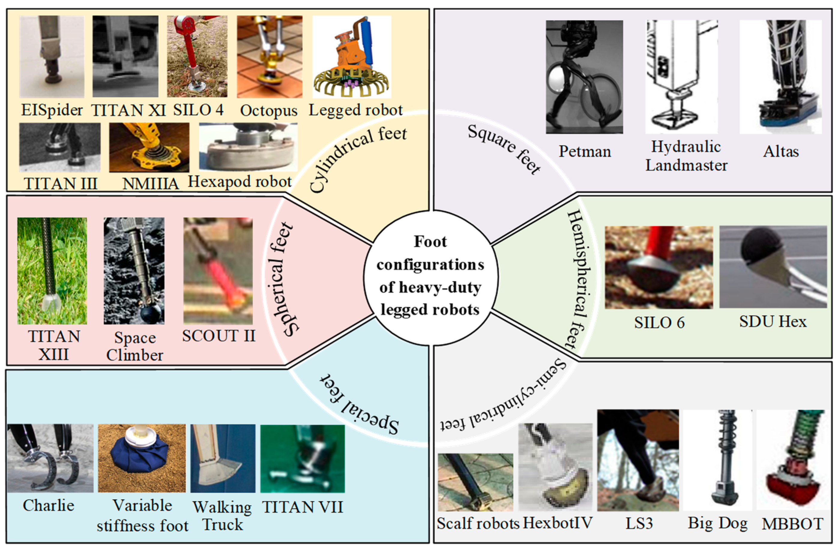
Spheres, ellipsoids, and rectangles have been found to be the most common shapes of feet [15]. Common configurations such as cylindrical feet, semi-cylindrical feet, spherical feet, hemispherical feet, square feet, and special feet are summarized.

Cylindrical Supporting Foot Configurations

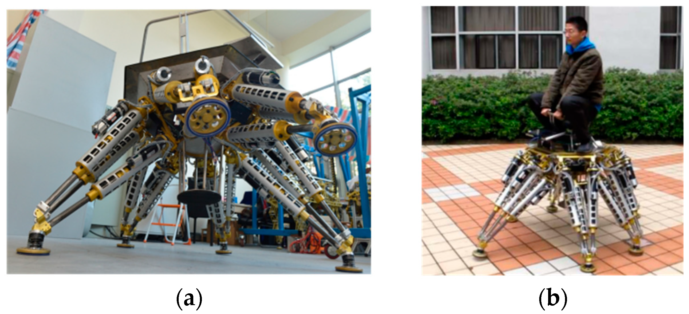
The Tokyo Institute of Technology has developed the TITAN series of robots. In 2002, the latest generation model machine called TITAN XI was developed, and the robot is shown in Figure 2a. It is a hydraulically driven quadruped robot. The robot can walk steadily and continuously on slopes covered with reinforced concrete frames. It can achieve intermittent crawling gait based on map information. Terrain adaptive gait makes the robot’s motion more stable. The robot’s feet are cylindrical [16]. TITAN IX is a quadruped robot with cylindrical foot shapes for humanitarian landmine detection missions [17]. TITAN III is a quadruped robot with cylindrical feet [18], as shown in Figure 2b.
The COMET-IV robot developed by Chiba University is a heavy-duty hexapod robot based on hydraulic drive, as shown in Figure 2c. The weight of the robot is approximately 2120 kg. Its load-bearing capacity is approximately 424 kg. The overall size is approximately 2.8 m × 3.3 m × 2.5 m. Each leg has four degrees of freedom (DOFs). It can walk on uneven terrain. The robot’s feet are cylindrical [19].
The Dante II robot, designed for exploring planetary surfaces, operates semi-autonomously and is equipped with eight legs. It weighs 770 kg, has the capacity to carry a 130 kg payload, and is capable of navigating slopes up to 30 degrees. The feet of the robot are cylindrical [20].
The NMIIIA robot was successfully developed in 1985, as shown in Figure 2d. It is a crewed hexapod robot developed by the former Soviet Union during the implementation of lunar exploration activities. It is used for star surface exploration and load bearing. The robot has a mass of 750 kg, a load-bearing capacity of 80 kg, and a moving speed of 0.7 km/h. Its feet are cylindrical [1].
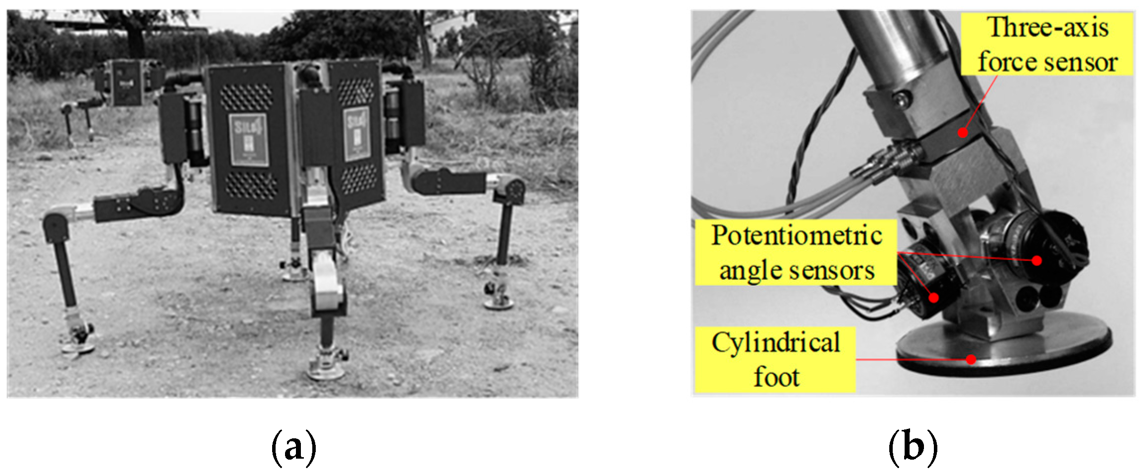
The SILO4 robot developed in Spain also has cylindrical feet [21]. The passive joint of the foot contains three rotational degrees of freedom (DOFs). The three-axis force sensors are installed on the robot’s feet. The outdoor experiment and ankle joint are shown in Figure 3.
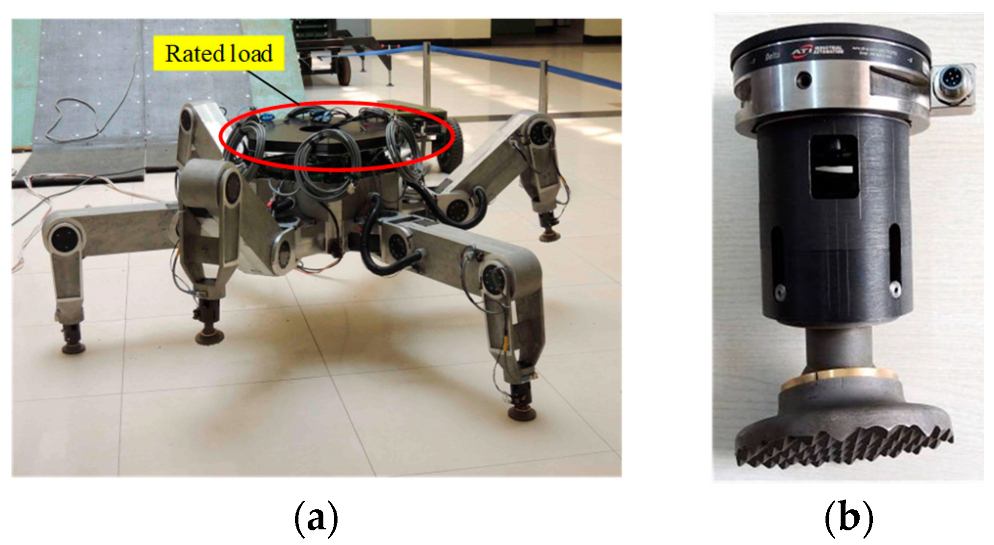
Zhuang developed a terrain electric-driven hexapod robot with a high load ratio, ElSpider. Six supporting legs of the robot are uniformly distributed on the body of the central symmetric structure. A single leg adopts a structure with three active and four passive degrees of freedom. It has a weight of approximately 300 kg. The rated load of ElSpider is greater than 155 kg, as shown in Figure 4a. Its overall size is approximately 1.9 m × 1.9 m × 1.0 m. It can cross obstacles with a height greater than 0.3 m, cross trenches with a width greater than 0.3 m, walk regularly at a speed of 0.16 m/s, and climb a maximum slope of 35°. The robot’s feet are cylindrical [22,23,24]. The six dimensions force sensors are also installed on the feet to measure the foot–terrain forces, as shown in Figure 4b.
A P-P structured hexapod Octopus robot was developed by Professor Gao F’s team from the School of Mechanical and Power Engineering at Shanghai Jiao Tong University. The robot’s body adopts a symmetrical design. It always maintains three supporting legs to support the body during walking, with good stability and maneuverability. Its speed is 1.2 km/h, and its load-bearing capacity is 200 kg. The Octopus robot adopts cylindrical configurations at the feet. But unlike the other feet of heavy-duty legged robots, the middle of the cylindrical foot is hollow. Its structure can effectively reduce the mass of the robot’s feet. And springs are installed above the feet to provide cushioning and shock absorption [26,27,28]. The indoor experiment is shown in Figure 5a. The load-bearing progress is shown in Figure 5b.
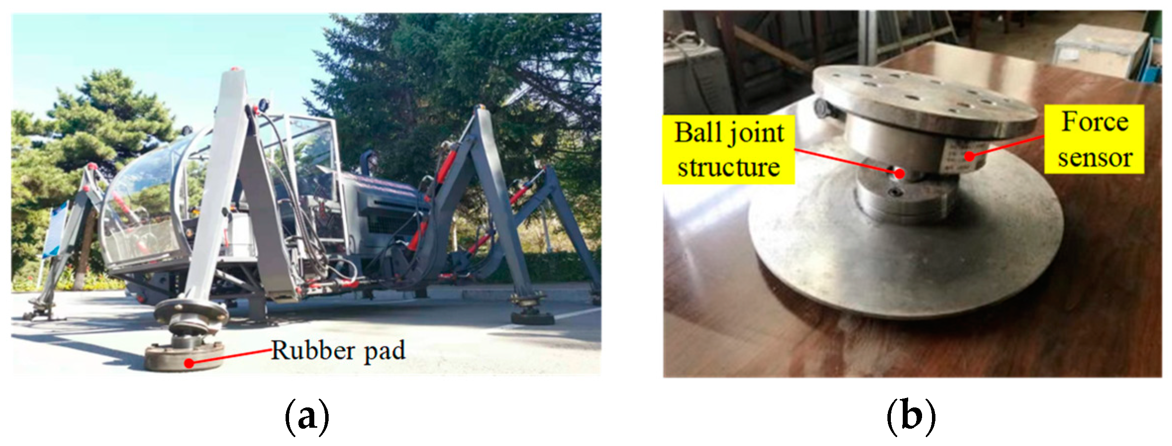
Researchers from Jilin University have designed a heavy-duty hexapod robot [30,31,32]. The feet are designed as ball joint structures, and force sensors are connected in series above the ball joints to detect whether the feet are firmly pressed against the terrain. There are reset springs parallel to the ball joints between the upper and the lower plates of the ball joints. They are used for feet to avoid sticking during the process of stepping on the terrain due to the large deflection angle of the foot bottom. Thick rubber pads are installed at the bottom of the feet to cushion the landing of the feet. The prototype of the heavy-duty hexapod robot and its foot are, respectively, shown in Figure 6a,b.
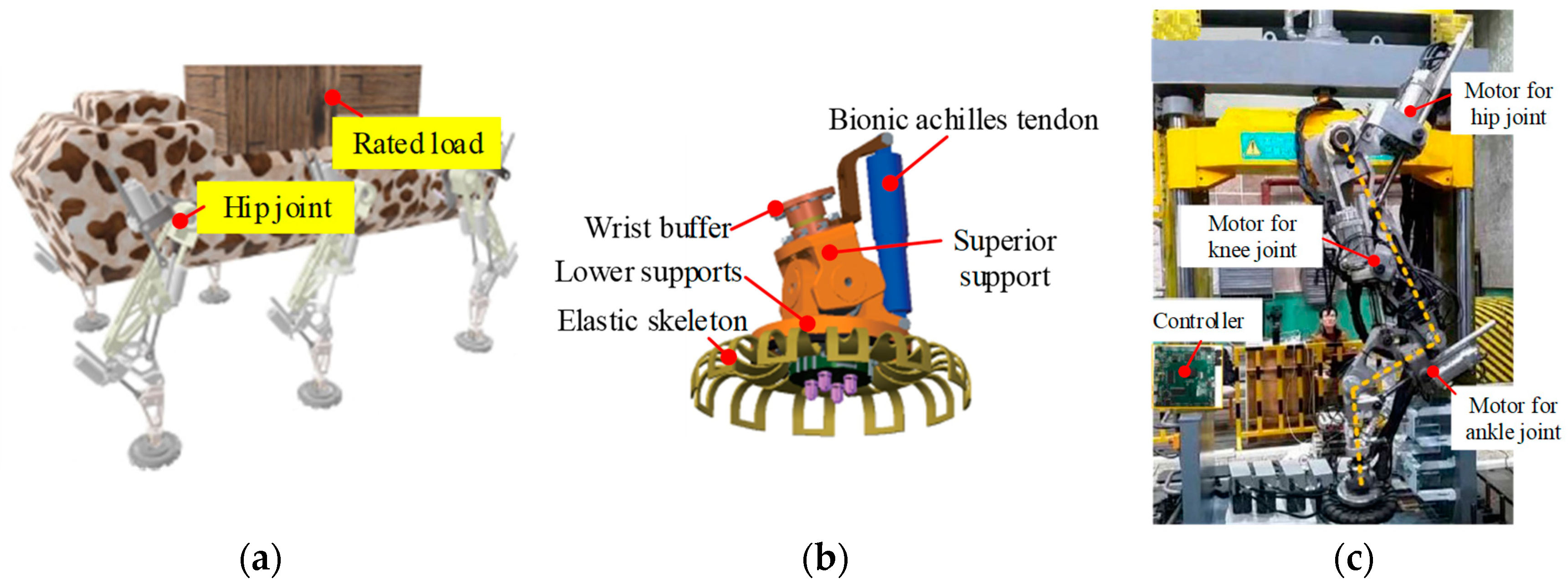
On the basis of the investigation of the heavy-duty legged robot, researchers from Huazhong University of Science and Technology present a novel foot structure for the heavy-duty legged robot. Its highly adaptable foot system with significant adhesion can be utilized to navigate extreme roads and complex terrains, including mountainous areas and swamps. The foot design, inspired by mountain-dwelling creatures, has been crafted to ensure substantial adhesion and enhanced adaptability [33,34]. The feet are installed on the heavy-duty legged robot, as shown in Figure 7a. The robot foot and single leg are, respectively, shown in Figure 7b,c.
The advantage of cylindrical feet is that they have a large contact area with the terrain. Large contact areas can provide greater adhesion to withstand heavy loads. At the same time, the heavy-duty legged robots equipped with cylindrical flat feet are suitable for long-distance transportation. The disadvantage is that it is necessary to design a swing structure, otherwise it cannot walk stably. The stress distribution model of the cylindrical foot of the heavy-duty legged robots is shown in Equation (1). Then
F N t = σ t × A F T t = τ t × A
where FN is the normal support force of the foot. FT is the tangential driving force of the foot. A is the contact area between the foot and the terrain.

Semi-Cylindrical Supporting Foot Configurations

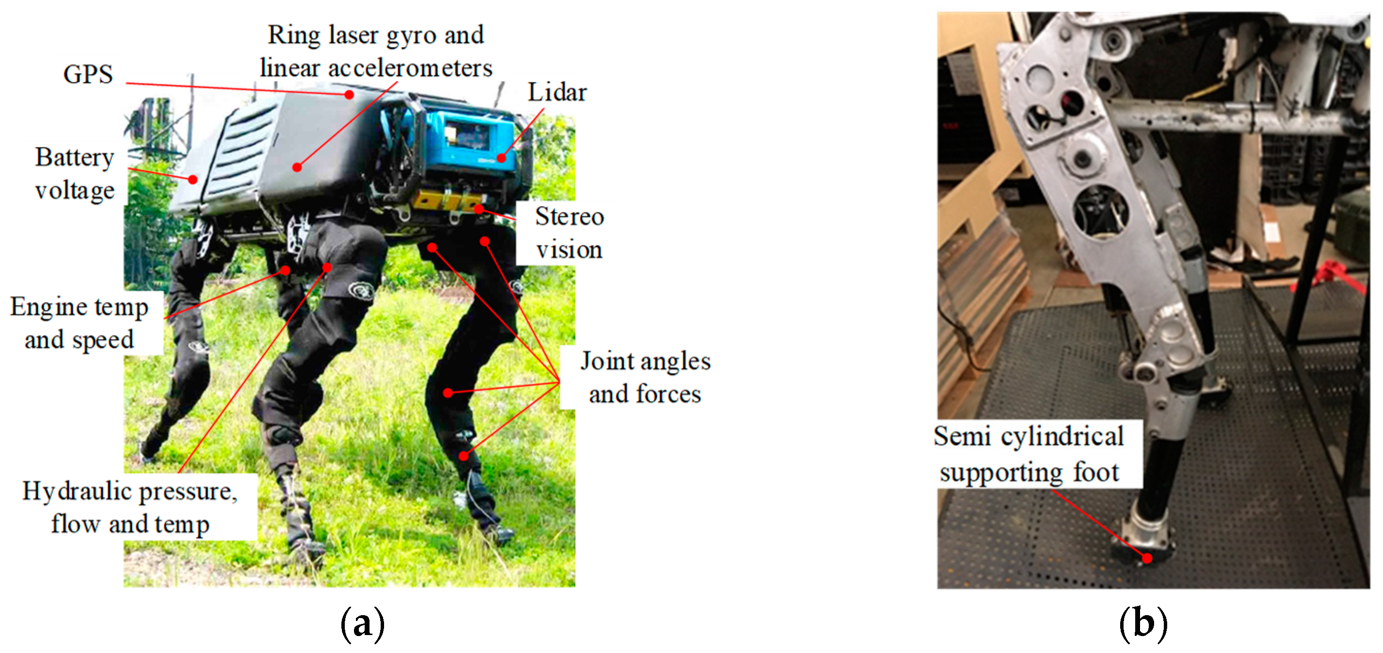
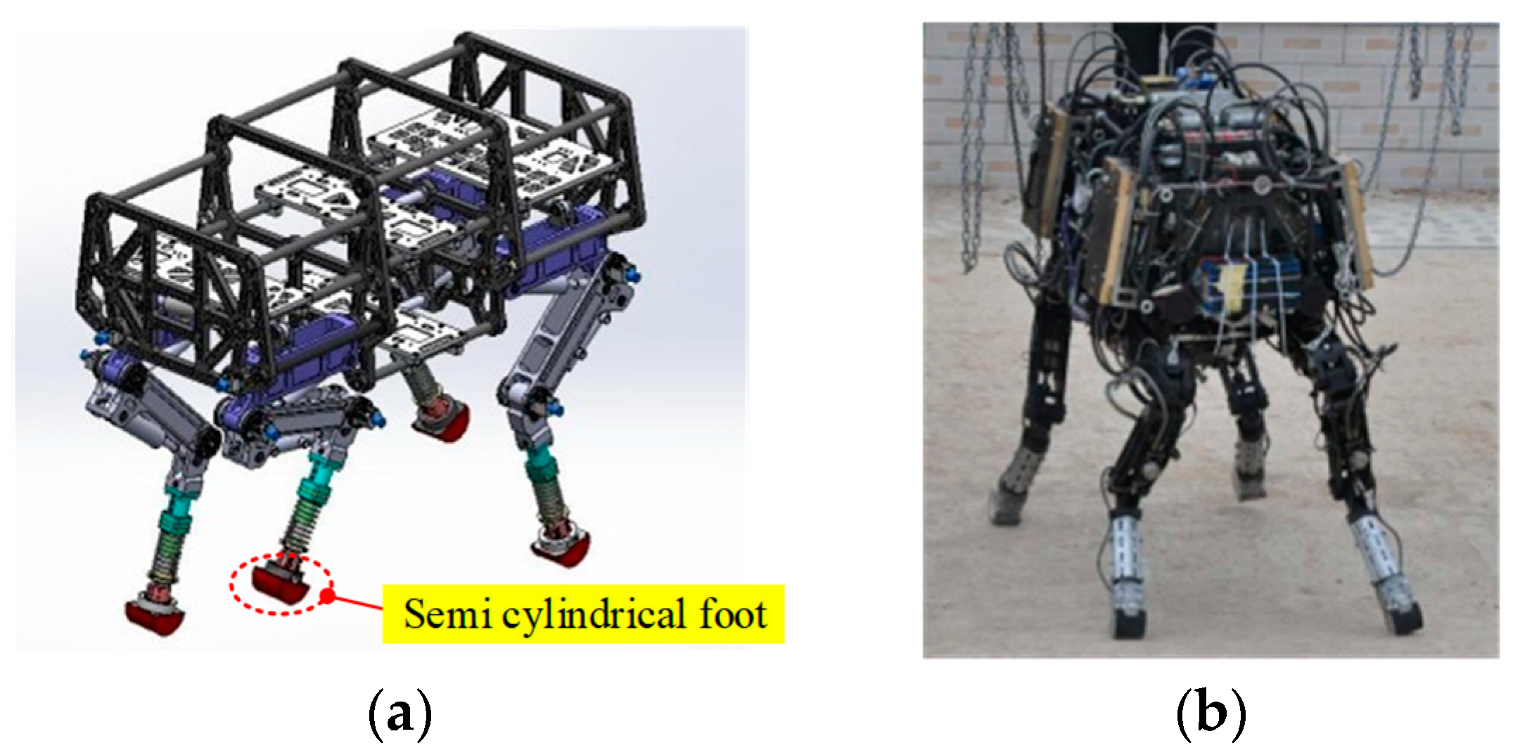
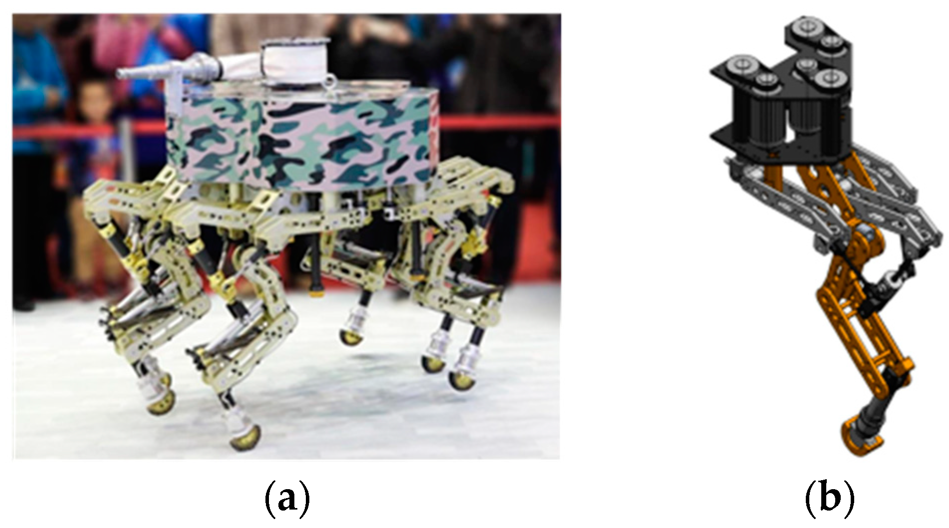
The Big Dog robot [35,36,37] developed by Boston Dynamics in the United States is a quadruped robot. The main components of the robot are shown in Figure 8a. It has full flexibility and can stand, squat, and move. The crawling speed is 0.2 m/s, the jogging speed is 1.6 m/s, and the jumping speed can reach 3.1 m/s in laboratory testing. The weight is approximately 109 kg, and the size is 1.1 m × 1 m × 0.3 m. The feet of the Big Dog robot are semi-cylindrical, as shown in Figure 8b. The Big Dog robot can pass through rock slopes up to 60° and has excellent adaptability to complex terrain.
Researchers at Huazhong University of Science and Technology have developed a hydraulic-driven quadruped robot, MBBOT [38,39]. Each leg of the robot includes four active degrees of freedom. The total mass of the robot is 140 kg. The feet of the four legs are also equipped with three-dimensional force sensors to detect the magnitude of the force between the legs and the external environment. The 3D model of the robot MBBOT is shown in Figure 9a. The prototype of the robot MBBOT is shown in Figure 9b.
Researchers from Shanghai Jiao Tong University have designed a disaster relief hexapod robot, HexbotIV [42,43,44]. The overall dimension of the robot is about 1.10 m × 0.72 m × 1.00 m. The robot has a total mass of 268 kg and can provide a load of 50 kg. In addition, to reduce the impact of the robot during movement, semi-cylindrical rubber cushions are installed at the end of the feet. The prototype of HexbotIV is shown in Figure 10a. The three-dimensional drawing of the parallel mechanism leg with an erect posture is shown in Figure 10b.
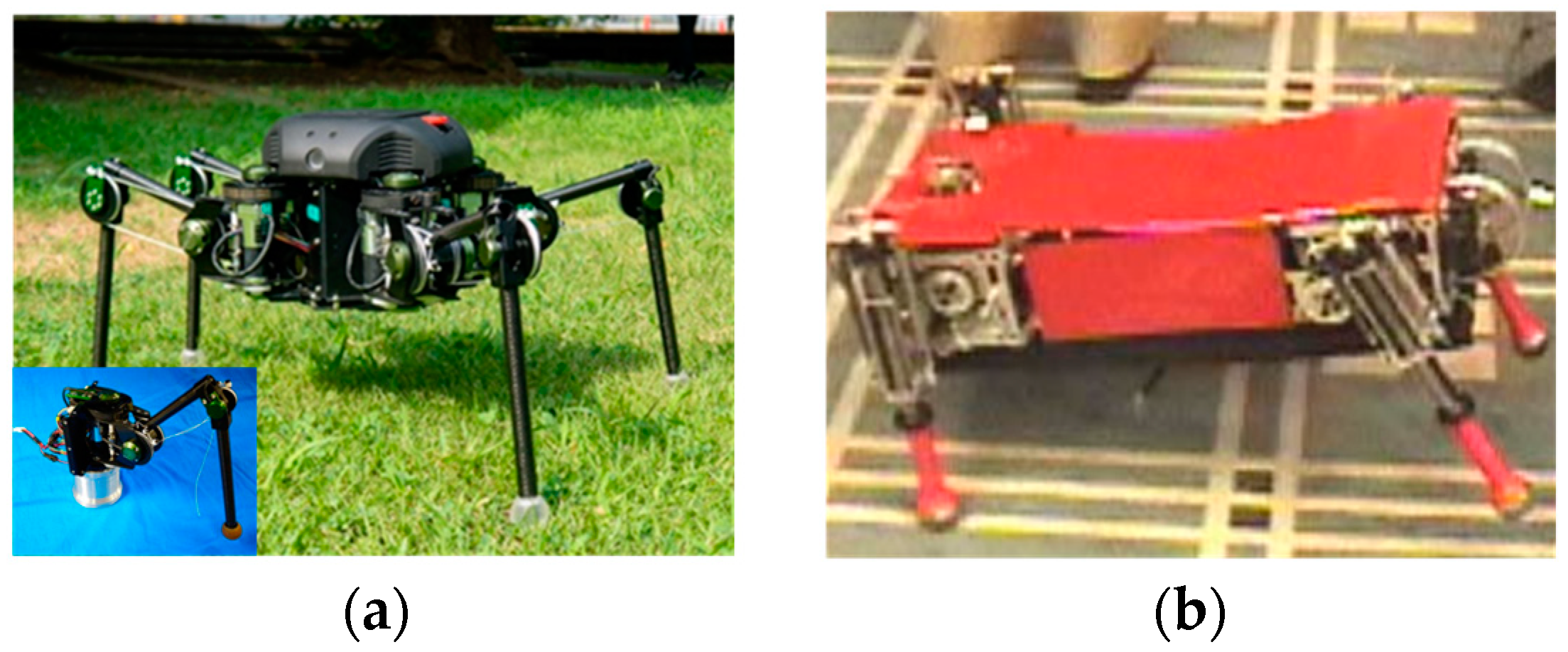
LS3 is tailored for the Marine Corps to handle cargo, as shown in Figure 11a. It can bear a payload of approximately 182 kg, carry enough fuel to sustain for 24 h, and cover approximately 32.2 km. Its feet are semi-cylindrical [45].
The SCalf-I robot, SCalf-II robot, and SCalf-III robot developed by the research team of Shandong University are all quadruped hydraulic heavy-duty robots, as shown in Figure 11b–d, respectively. The payload–total mass ratio can reach 0.5. The feet are designed as semi-cylindrical shapes [46,47,48].
Compared with cylindrical feet, the semi-cylindrical feet of heavy-duty legged robots can effectively reduce the mass of the robot. However, the contact surface area between the semi-cylindrical feet and the terrain is relatively small for the cylindrical feet. Then, the stability of the heavy-duty legged robots is slightly worse than that of the cylindrical feet.

Spherical Supporting Foot Configurations

In 2010, the DFKI Robot Innovation Center at the University of Bremen designed a highly adaptable free-climbing robot (Space Climber) for the steep slopes of lunar craters. The robot feet are mechanisms similar to eagle claws, as shown in Figure 12a. The feet can effectively improve the terrain adhesion ability of the detector [49]. In 2012, to overcome the limited mobility of detectors in unstructured environments, such as obstacles, normal steep slopes, and steep slopes of fine-grained soil, the Space Climber feet were changed to spherical shapes [50]. The updated robot feet are shown in Figure 12b. The spherical feet can withstand collisions with hard surfaces or obstacles and provide an increased contact area when sinking into the soil. The spherical feet have the natural advantage of having the same tangential performance in different directions of motion.
TITAN XIII is a quadruped robot, as shown in Figure 13a. Each leg has three degrees of freedom (DOFs). The body mass is 5.65 kg, and the load is 5.0 kg. Its feet shapes are spherical. It can move on rough and irregular terrains by selecting suitable footholds and changing the robot’s posture [51]. Ohtsuka S invented terrain-adaptive feet for the TITAN XIII robot. Its feet can passively adapt to rough terrain, including bumps and tilts, while ensuring a stable foothold [52].
The SCOUT II robot [53] is a quadruped robot that can achieve a jumping gait, as shown in Figure 13b. Each leg has two degrees of freedom: a driving hip joint and a linear spring. The stable mobile control strategy can be achieved when it walks at a maximum speed of 0.9 m/s to 1.2 m/s. The dynamically stable legged robots lay greater emphasis on their terrain adaptability, making their movement more stable. The feet of the robot adopt hemispherical shapes to achieve the point contact between the foot and the terrain, which improves the stability of the robot in different terrains.
Based on the above statement, it can be very easy to come to a conclusion. The advantages of the spherical foot are that the mechanical structure design is simple, the tangential forces in all directions are equal, and it is very suitable for walking in soft soil or deserts. Meanwhile, the disadvantage of the spherical foot is that the contact between the foot and the terrain is point contact, with a relatively small contact area and low terrain friction, which is not conducive to the robot’s smooth walking. When the velocity angle of the foot tip coincides with the attitude angle, the stress distribution models of the spherical foot can be obtained, as shown in Equations (2) and (3). Then
F N = K δ m t + C δ n t δ ˙ p t sin η
F T = μ F N K δ m t + C δ n t δ ˙ p t cos η μ F N
F T = K δ m t + C δ n t δ ˙ p t cos η K δ m t + C δ n t δ ˙ p t cos η < μ F N
where K is the spring coefficient, C is the damping coefficient, μ is the friction coefficient, m and q are the parameters to be identified, and n is the model parameter.

Hemispherical Supporting Foot Configurations

The SILO6 robot [54] is a hexapod robot system used for humanitarian demining missions. According to the static stability design, a triangular gait is adopted to achieve the maximum speed of the robot. The foot is fixed to the hemisphere of the ankle, with a simple structure and good performance on the hard terrain. But increasing the radius of the ball on the loose terrain will reduce the sinking amount. At the same time, on hard terrain, the radius of the ball is too large to make it attempt to rotate, changing the positions of the foot’s support. The SILO-6 robot is shown in Figure 14a.
The SDU Hex electric hexapod robot [55] designed by researchers from Shandong University in 2021 can achieve leg arm reuse and strong operation. The structure of the entire SDU Hex robot is shown in Figure 14b. The feet adopt hemispherical structures. And the feet are equipped with a high adhesion damping rubber pattern and air chamber, reducing the impact force during the interaction between the foot and the terrain.
The hemispherical feet and spherical feet have the same contact methods with the terrain, both of which are point contact. Therefore, the mechanical models of the two above can be generalized and will not be explained in detail here.

Square Supporting Foot Configurations

The Hydraulic Landmaster robot is a large hexapod robot that works on steep forest terrain, as shown in Figure 15. The weight of the robot is 3950 kg, with a rated load of 1000 kg. The size is 3.6 m × 2.3 m × 2.6 m, with a maximum height of 4.5 m, and a maximum height of 1.7 m when passing through obstacles. Electric Landmaster 3 is the previous generation of Hydraulic Landmaster. The electric Landmaster 3 robot has a weight of 82 kg and a rated load of 30 kg. Both robots have the same model structure with principle, and both have significant heavy-duty capacity. Square feet are used at the feet of robots [1].
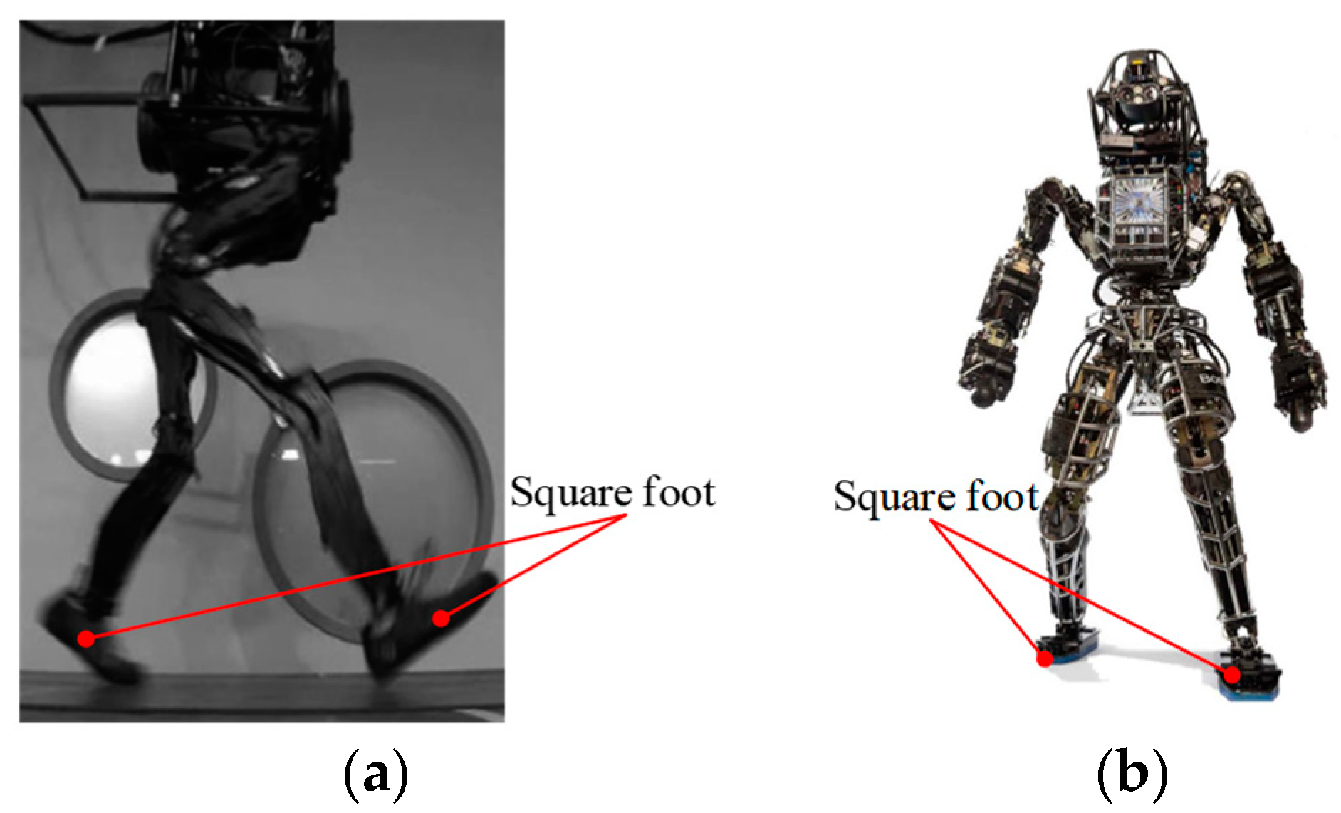
The Petman robot [56] developed in the United States is a humanoid bipedal robot, as shown in Figure 16a. The maximum speed can reach 7.2 km/h. The robot’s use of Big Dog’s leg structure and electronic equipment enables faster design and testing experiments. When pushing moderately from the side while walking, it can restore its balance. Square feet are used at the feet. Another humanoid bipedal robot Altas [57] also adopts square foot structures, as shown in Figure 16b.
The advantages of square configuration are that the design is relatively simple, and no spiral structure design is required. The disadvantage is that it cannot adapt to more complex terrain. The rectangular foot–terrain mechanics models can be obtained by multiplying the average stress distribution with the plantar area. The rectangular foot–terrain mechanics models can be given in Equation (4). Then
F N t = k c a + k φ a b δ n F T t = a b c + F N t tan φ
where a, b, and c are the dimensions of the long side, wide side, and high side of the rectangular foot, respectively.

Special Supporting Foot Configurations

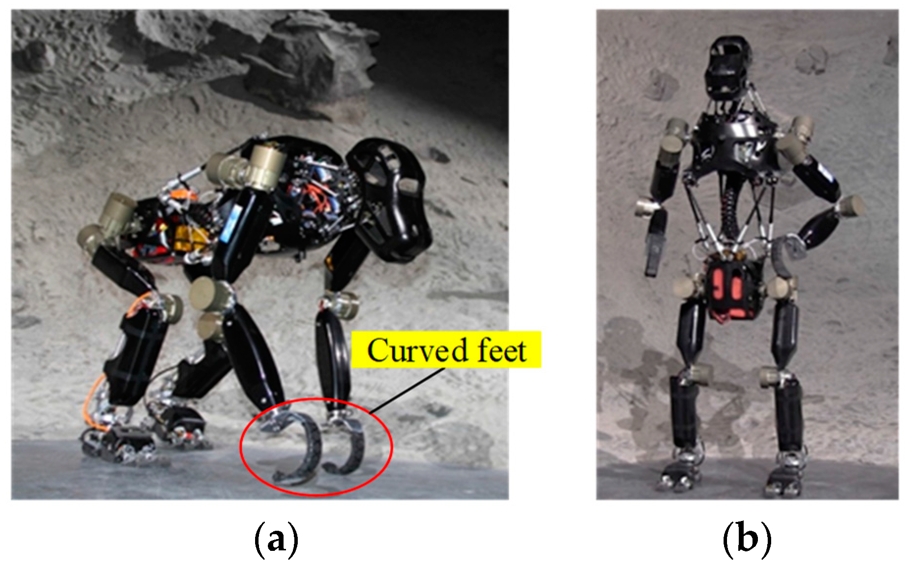
Charlie is a quadruped robot designed based on primitive humans. The feet of the front legs adopt curved structures [58,59]. The quadruped forward movement of the robot can be achieved. The Charlie robot can walk upright with both feet. The quadruped and bipedal walking postures are, respectively, shown in Figure 17a,b.
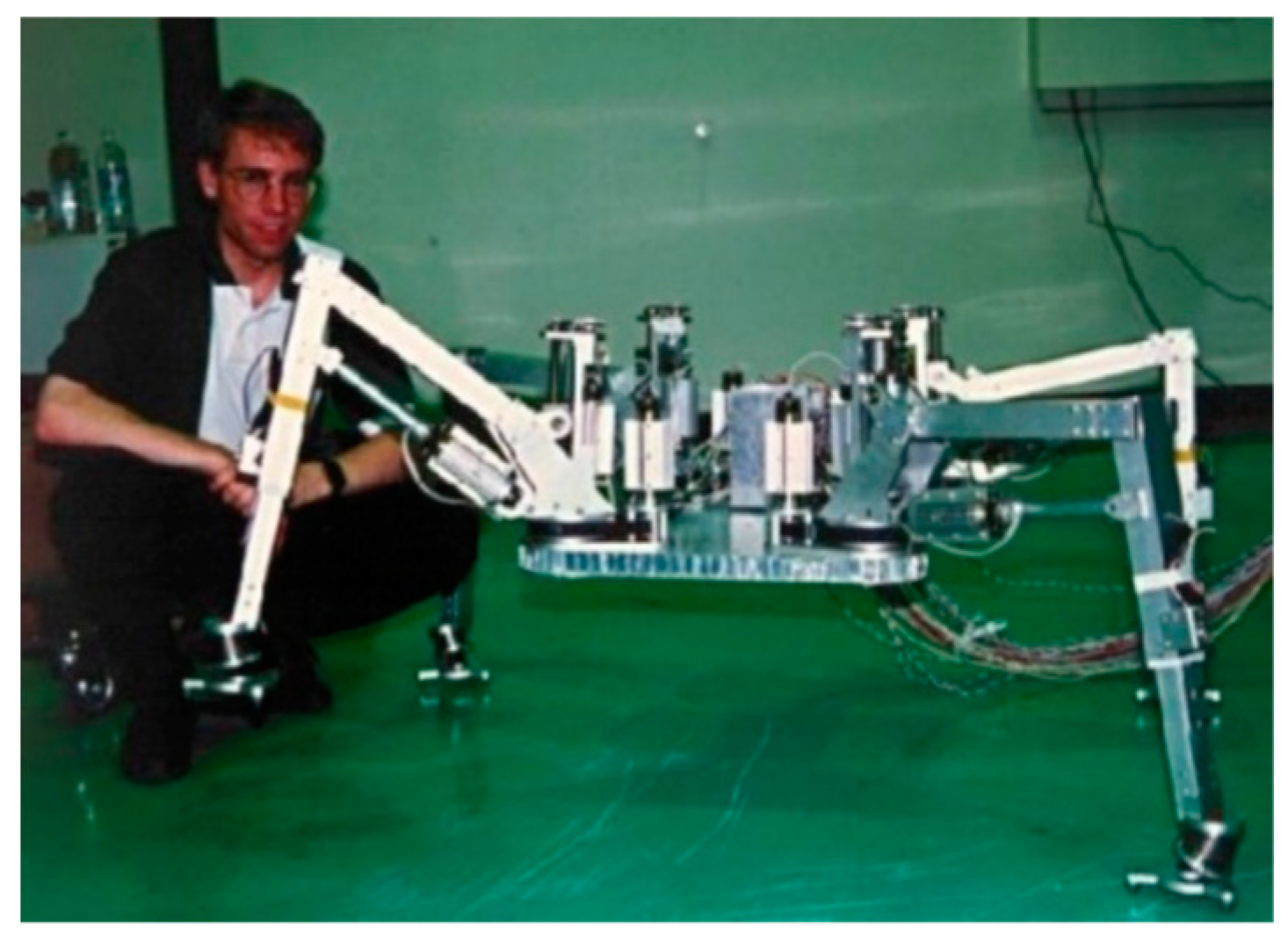
In the 1960s, General Electric designed a quadruped walking truck for the US Army, as shown in Figure 18. The shape of the foot is curved [60]. The advantages of curved feet are that they have simpler structures and a lighter weight. Their disadvantage is that they cannot carry a larger mass.
Hirose proposed a passive terrain adaptive foot mechanism [61]. A sensor mechanism installed on the ankle and three fixed claws at the bottom of the foot are included. The effectiveness of these new mechanisms was verified through the TITAN VII robot walking experiment. The TITAN VII robot is shown in Figure 19.
Researchers are inspired by the large surface area to volume ratio of X-shaped concrete piles in geotechnical engineering. An X-shaped foot with holes is designed and the relationship between sinkage and bearing capacity is analyzed. When subjected to an identical load, the sinkage experienced by an X-shaped foot with holes is less compared to that of other foot shapes [62,63]. It is beneficial for reducing the sinkage of the robot and improving walking stability.
Combining sinkage with multi-body dynamics, the characteristics of the circular foot, X-shaped foot, and improved X-shaped foot were analyzed for their sinkage and walking stability. It can be obtained that the improved X-shaped foot has the best capability of increasing the support length and lateral force of the robot. The horizontal cross-sectional shapes of the three types of feet are shown in Figure 20.
Chopra [64] proposed a foot design that can passively change shape and actively change stiffness to improve the robot’s motion on the granular media. The foot is shown in Figure 21a. It has been proven that using a foot design with wrinkles is soft before falling and rigid during shearing. It can reduce foot acceleration at joints, traction force, and penetration depth, and obtain a greater resistance coefficient when the foot is at a certain displacement. The contact process between the foot and the terrain is shown in Figure 21b.
The advantages of robot feet with passive adaptive joints are their simple mechanical structures, simple mobility control policies, and the ability to adjust relative positions and angles according to changes in the environment. Robot feet with passive adaptive joints can be divided into cylindrical feet, semi-cylindrical feet, spherical feet, hemispherical feet, square feet, and special feet. The most widely used configuration for the supporting feet of heavy-duty legged robots is cylindrical. The performance indicators of the released heavy-duty legged robots with passive adaptive joints are shown in Table 1. The different foot configurations with the passive adaptive joints of heavy-duty legged robots are shown in Figure 22. Due to the reasons of technical confidentiality and copyright, the specific weight-bearing quality of heavy-duty robots that can be consulted is limited.
In terms of configuration, the cylindrical shape is symmetrical in all directions, which can make the normal and the tangential forces on the robot’s supporting feet more uniform. The robot’s foot slip is effectively suppressed. It plays an irreplaceable role in the movement of heavy-duty legged robots on unstructured terrain. The cylindrical foot has a larger contact area with the terrain, which is compared to the smaller contact area of other feet. For the heavy-duty legged robots, increasing the area between feet and terrain in the process of operation can reduce the pressure on the foot per unit area and improve the support effect during the load-bearing period. However, the drawbacks of the robot feet with passive adaptive joints are also obvious. The structures cannot fully adapt to the changing terrain environment and actively control the foot posture.

2.1.2. Feet with Active Driving Joints

The mechanisms of feet with active driving joints in heavy-duty legged robots are generally more complex. Drive devices need to be installed to make them more difficult to control movement and more cost-effective compared to feet with passive adaptive joints. They have not been widely applied in current research on heavy-duty legged robots.
In 1996, Hong [65] from the South Korean University of Science and Technology was inspired by the structure of umbrellas and designed a point contact underactuated robotic foot. The oil in and out of the hydraulic cylinder in the middle of the foot will change the opening and closing state of the toes. The point contact between the feet and the terrain enhances the adaptability of the robot’s feet to the rough terrain. This type of foot is applied by researchers to a quadruped robot, as shown in Figure 23a.
In 2007, Yamamoto, Sugihara, Nakamura, and others from the University of Tokyo in Japan designed humanoid robot feet. The robot feet are installed on the UT-µ2 robot, as shown in Figure 23b. The characteristic of the robot’s feet is that the toe mechanism does not use the commonly used hinge type rotating pair, but instead uses a parallel four-link mechanism. Through analysis, it is shown that the combined moment of force at the joints of the parallel four-link-type toe mechanism is smaller than that of the hinge-type toe joint during most motion periods [66].
In 2009, Borovac and Slavnic from the University of Novi Sad used motion analysis of human feet to design a humanoid robot foot. The type of robot foot not only has passive toe joints but also active toe joints, making humanoid robots able to walk more smoothly and improving their walking ability [67]. The robot foot with an active driving unit is shown in Figure 23c.
Nabulsi from the Polytechnic University of Madrid designed a mountain climbing robot called Roboclimber, as shown in Figure 23d. It adds hydraulic cylinders above the feet of the robot. Adjusting the foot–terrain force is carried out by changing the oil inlet and outlet quantities of the hydraulic cylinders. The friction force between the robot’s feet and the terrain is adjusted. The mechanical performance of the foot–terrain contact surface is improved [68].
In 2010, Collins and Kuo from the University of Delft in the Netherlands designed a robotic foot that could utilize energy more effectively during walking. Because people usually waste a lot of beneficial energy when walking, they developed a micro-driven controlled humanoid foot [69]. Being able to more fully utilize the energy lost in human legs and ankle joints during walking, the energy utilization rate has increased by 23% compared to normal walking. The physical image of the robot foot is shown in Figure 24a. The 3D structure diagram of the robot foot is shown in Figure 24b.
Compared with robot feet with passive adaptive joints, robot feet with active adaptive joints have certain advantages. They can actively adjust the configurations of their feet based on the shape of the terrain, thereby increasing the contact area between the feet and the terrain. When subjected to normal force from the vertical direction and tangential force from the horizontal direction, adjusting the feet to reach the positions where the force is most evenly applied improves the stability of the robot. Their significant drawbacks are a more complex structural design and high control difficulty compared to robot feet with passive adaptive joints. At present, there is little research on robot feet with active adaptive joints in heavy-duty legged robots.

2.2. Plantar Patterns of Supporting Foot of Legged Robots

The legged robots mainly rely on the friction force between their feet and the terrain when walking. When the friction force is high, the sliding phenomenon of the robot’s feet will be reduced. Designing and installing some structures on the bottom of the robot’s feet is carried out to improve their adhesion to the terrain. In current research, it has been found that the research on the foot patterns of heavy-duty legged robots is not yet in-depth enough.
Song [70] from the Harbin Institute of Technology conducted an analysis of the equivalent adhesion coefficient of typical foot patterns. The model of robot foot–terrain interaction attachment has been established. The equivalent adhesion coefficient of different foot configurations (flat foot, nail foot, single-baffle foot, and multi-baffle foot) can be calculated. The different feet used for testing in the experiment are shown in Figure 25. The higher the coefficient of adhesion, the better the adhesion characteristics of the robot. The conclusion is that the multi-baffle foot has the best adhesion performance, followed by the single-baffle foot, nail foot, and flat foot.
Zou [71] from the Dalian University of Technology designed a new plantar pattern. The middle part adopts horizontal stripes perpendicular to the robot’s forward direction, while the remaining parts use 45° diagonal stripes to enhance the anti-slip ability of the foot. The design of the plantar pattern structure is to first establish a simulation model for the terrain action and an evaluation method for adhesion performance. On that basis, the plantar adhesion performance is the optimization objective, and the structural parameters of the plantar pattern are the optimization variables. The response surface method is used to optimize the design of the foot pattern. Simulation and experimental verification are conducted. Compared to the reference offroad tire design, the adhesion coefficient of the plantar pattern is increased by 7.41%. The optimized plantar pattern is shown in Figure 26a. The original plantar pattern is shown in Figure 26b.
Li [72] from the Dalian University of Technology designed the rubber feet of the heavy-duty robot. The plantar patterns of the feet adopt a mixed pattern design, with a crisscrossing pattern in the middle. The offroad patterns with wider grooves are evenly arranged around at an angle of 15°. The rubber feet can be designed with existing vehicle tire patterns as the research background. Considering the combination of the plantar patterns and the feet, it is equipped with patterned blocks, patterned grooves, and base glue. The calculation of the adhesion and climbing angle of the plantar patterns has also been carried out. Li [73,74,75] conducted in-depth research on the effects of plantar pattern depth, groove width, and pattern direction on the friction coefficient. The results show that on the wet terrain, the deeper the pattern, the higher the friction coefficient. Wide patterned grooves have a higher coefficient of friction. The friction coefficients of horizontal and 45° patterns are relatively high. Their anti-slip performance is good. The different groove designs of the plantar patterns are shown in Figure 27a–c.
The heavy-duty legged robot relies on the reaction forces provided by the terrain to move. The foot serves as the only interface for direct contact with the terrain, which is a key component that ensures the excellent adaptability of the heavy-duty legged robots to unstructured terrain environments.

3. Dynamics Analysis of Robot

The robot foot–terrain interaction mechanics is a branch of contact mechanics. Studying the interaction process between the machinery and working terrain is of great significance when studying the design of foot mechanisms and the kinematic simulation of robot bodies. An accurate foot–terrain mechanics model is the basic condition for designing anti-sinkage, high-traction, and lightweight feet. At the same time, it can also optimize the path planning and motion control of the robots, thereby improving the terrain adaptability of the heavy-duty legged robots.
The current research on the terrain mechanics of wheeled robots has been very extensive. There is relatively little research on the terrain mechanics of legged robots [76,77]. The current research on the foot–terrain mechanical interactions of the legged robots will draw on the existing wheel–terrain mechanical models of the wheeled robots. Zhuang [78] believes that legged robots can flexibly walk on rough and uneven surfaces, but due to the presence of multiple driving joints, the power consumption of their mobile systems is often high. Therefore, studying the foot–terrain interaction mechanics of heavy-duty legged robots can also provide a reference for low-power research on robots.
The legged robots have the characteristics of discontinuous motion, large foot impact, and multiple degrees of control freedom. Each walk of the robot is equivalent to a collision between feet and terrain. The foot–terrain interaction models are used to analyze the relationship between terrain characteristic parameters and foot parameters of normal and tangential forces. In addition to the force from the normal direction, it is also subjected to tangential force including the horizontal direction. The normal force acting on a heavy-duty legged robot during movement is much greater than the tangential force, Liu [79] conducted a static analysis of the feet of an electrically driven heavy-duty hexapod robot under a tripod gait. A trend chart of the changes in the normal force of the feet is obtained. The walking method that can achieve the most average distribution of each foot force is determined.
During the walking process of the legged robot, the contact between the foot and the terrain not only exhibits normal relative motion but also tangential relative motion. It generates tangential relative motion and tangential friction. Taking into account both normal relative motion and tangential relative motion, analyzing the foot–terrain interactions generated by these two aspects is beneficial for further precise motion control and stable gait planning of the legged robots.

3.1. Models of Pressure–Sinkage for Mobile Robot

Regarding the study of terrain mechanics, the study of wheel–earth interaction mechanics started early and has been very extensive. The use of the wheel–terrain interactions of the wheeled robots as the basis for the study of foot–terrain mechanics of the legged robots has been recognized. When pressure continuously acts on the soil below through the contact surface, the part of the soil will diffuse towards the soil around the contact surface. When a compacted area is fully formed, the movement of surrounding soil particles becomes stable. The pressure–sinkage model is a representation of the pressure–sinkage relationship. For the convenience of elaboration, it is assumed that the depth of soil sinkage is uniform.

3.1.1. Models for Pressure–Sinkage at Zero Slip Conditions

A Theoretical Exploration of the Wheeled Robots

In 1913, Bernstein proposed the relationship between the pressure applied to the soil and the sinkage after conducting relevant experiments on the relationship between pressure and sinkage [80,81]. The updated model is shown in Equation (5). Then
p = k z n
where n is the model parameter, and n > 0.
In the mid-19th century, Bekker conducted specialized research on the plasticity of soil subsidence and driving resistance [82,83,84] In classical soil mechanics, when considering the Bernstein model, the sinkage modulus k is bifurcated into two distinct components. One part represents the influence of the cohesion of the soil itself, while the other part represents the influence of the internal shear angle. The shear angle mentioned here is actually the friction angle. The Bekker model also considers the geometric shape of the contact surface. The Bekker model played an irreplaceable role in evaluating the motion performance of the wheeled robots, the tracked robots, and the legged robots [85]. The Bekker model is shown in Equation (6). Then
p = k c b + k ϕ z n
where b is the smaller dimension of the contact patch. kc is a sinkage modulus influenced by soil cohesion. kΦ is a sinkage modulus influenced by the soil friction angle.
Reece introduced two distinct pressure–sinkage models, each tailored to specific soil conditions. The first model, as shown in Equation (7), features model parameters whose dimensions remain constant regardless of the sinkage index, which stands in contrast to the Bekker model. On the other hand, the second equation, as shown in Equation (8), employs dimensionless model parameters and is primarily designed for highly compacted soil [86]. Reece’s second model is particularly suited for very dense soil, showcasing its versatility. Then
p = k 1 + k 2 b z / b n
Then
p = c k c + γ k ϕ b z / b n
where k1 and k2 are model parameters. c is the soil stickiness, and γ is the unit weight of the soil.
Notably, the Reece model proves highly effective for wheeled robots navigating frictionless clay and firm soil with minimal sinkage. It represents a substantial enhancement over the Bekker model. However, it is worth noting that the Reece model has not undergone extensive testing in softer clay soils, leaving room for further evaluation and refinement in these specific conditions.
Experimental curves showing pressure and sinkage are used to define the relationship between pressure and sinkage in soil. A semi-empirical hyperbolic law is established by Kacigin and Guskovt. By analyzing the compressive strength of the soil, two constants that can be utilized are proposed; they are the bearing capacity p0 and the soil compression coefficient k. The relationship between pressure and sinkage can be obtained, as shown in Equation (9). Then
p = p 0 1 exp 2 k z / p 0 1 + exp 2 k z / p 0
where p0 is the bearing capacity of the soil.
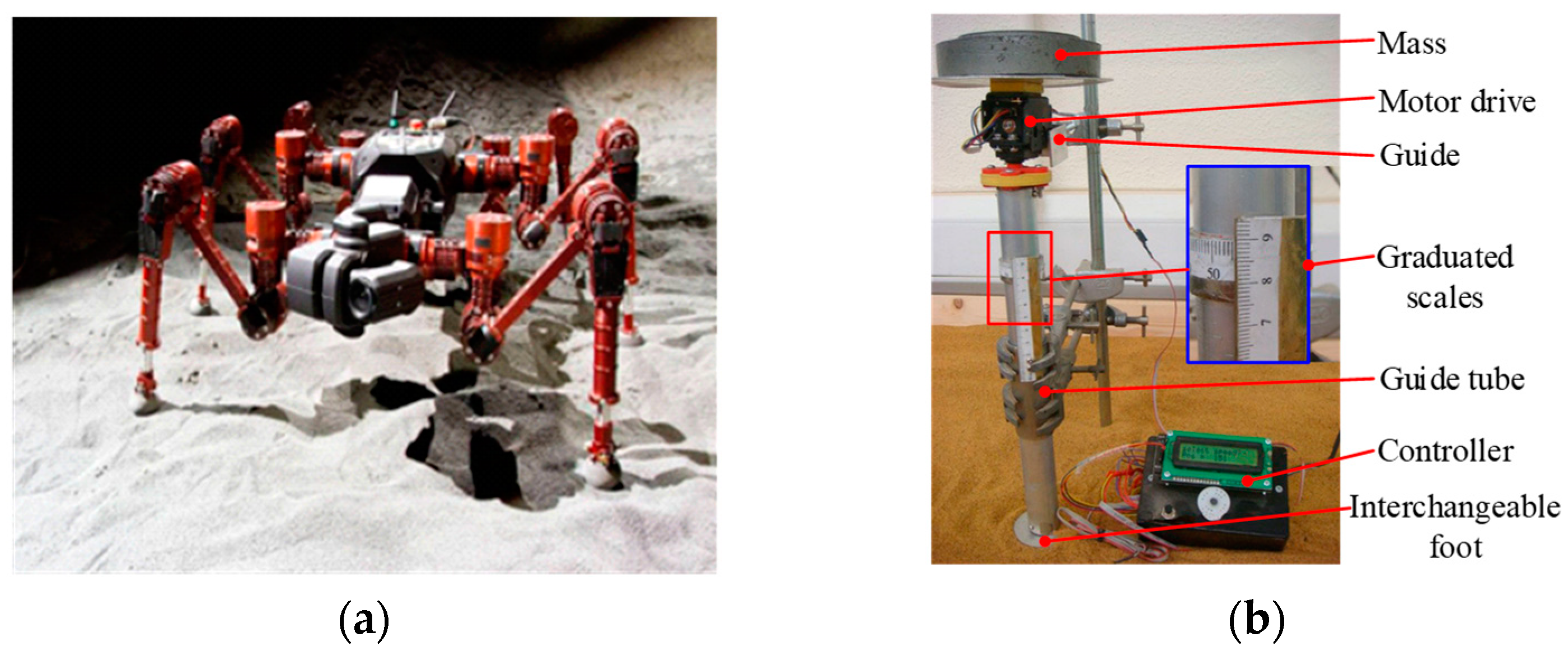
Gottenland and Bonoit [87] selected three standard soils: a sand type is used for soils with frictional properties, a silt type for soils with cohesion, and a silty sand type for soils exhibiting both cohesive and frictional characteristics. A pressure–sinkage model N2M was proposed for the interaction between circular contact surfaces and soil. The N2M model is shown in Equation (10). It considers the mechanical behavior of the soil. Small vertical sinkage is similar to elastic behavior. For large sinkage, they are similar to plastic behavior. The initial linear function describes the linear relationship of sinkage pressure within the elastic and plastic areas of the sinkage pressure diagram. The subsequent composite function delineates the shift from the elastic to the plastic region. In the N2M model, distinct asymptotes in both the elastic and plastic sections differentiate the soil’s elastic and plastic properties. The sinkage equipment for experimental equipment is shown in Figure 28. Then
p = C m A m + s m A 1 m z 1 exp s 0 C m z A 1 m
where A is the diameter of the contact surface, Cm, and s0, sm, and m are model parameters.
The sinkage index N serves as a variable to represent the impact of terrain characteristics and various other factors. Ding formulated a model capable of mirroring the impact of normal load, the size of the plate or transmission, and slip on the relationship between pressure and sinkage [88]. The plate sinkage experiment is shown in Figure 29a. The pressure–sinkage relationship is shown in Figure 29b. The general form of the model that takes into account the influencing factors is shown in Equation (11). Then
p = k S z λ N
where kS is the stiffness modulus of the terrain, which plays a leading role in determining the load-bearing performance of the terrain, in Pa/m. λN is a dimensionless function that reflects other key factors.

A Theoretical Exploration of the Wheel-Legged Composite Robots

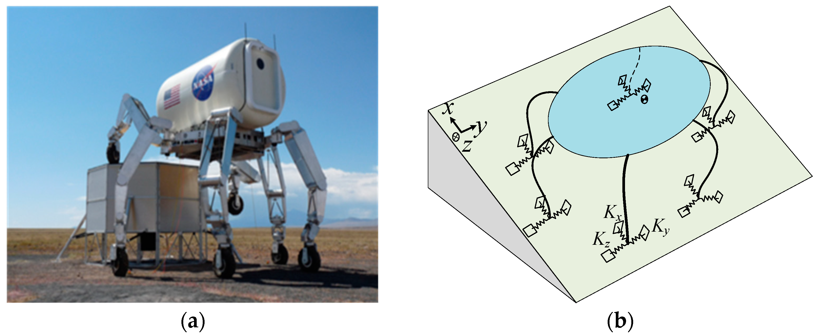
Hunt and Crossley proposed the Hunt–Crossley model. It describes the relationship between the equivalent stiffness and damping of the contact between the object and the terrain. The physical characteristics and the boundary conditions are fully revealed during the contact process [89]. The Hunt–Crossley model was applied by NASA to the study of the lunar hexapod robot ATHELETE. The wheels are modeled as three-dimensional springs to calculate reaction force and deformations [90]. The research results indicate that the model can accurately predict the sinking phenomenon of the robot and has sufficient accuracy for gait planning and execution. Future work can further improve the model to enhance prediction accuracy and apply it to more types of robots. NASA’s ATHLETE robot is shown in Figure 30a. The reaction force and deformation are shown in Figure 30b. The Hunt–Crossley model is shown in Equation (12). Then
F N = k N δ n 1 + C N δ ˙ m δ n 2       δ ˙ 0
where δ is the sum of foot and terrain deformations. CN is the damping coefficient. n1 and n2 are the indicators of the stiffness terms. m is the exponent of the damping term, which can be set to 0 (the linear spring damping model) or n1 (the simplified Hunt–Crossley model). kN is the equivalent stiffness coefficient.
Then, the equivalent stiffness kN can be obtained by Equation (13). Then
k N = k FN k TN k FN + k TN

A Theoretical Exploration of the Legged Robots

Youssef and Ali conducted comprehensive research on sandy soil and clay by integrating the bearing capacity model introduced by Terzaghi and Housel with the pressure–sinkage models of Bekker and Reece [91]. Considering the influence of the size and shape of the contact object, different parameters are provided for the shape of the contact surface, such as circular, square, rectangular, and elliptical. The geometric parameters of the flat plate are shown in Table 2. Through experimental verification, a new pressure–sinkage model is proposed, as shown in Equation (14). Then
p = k 1 + α b k 2 β n z / b n
where k1 and k2 are the soil shear strength values. α and β are dimensionless geometric constants.
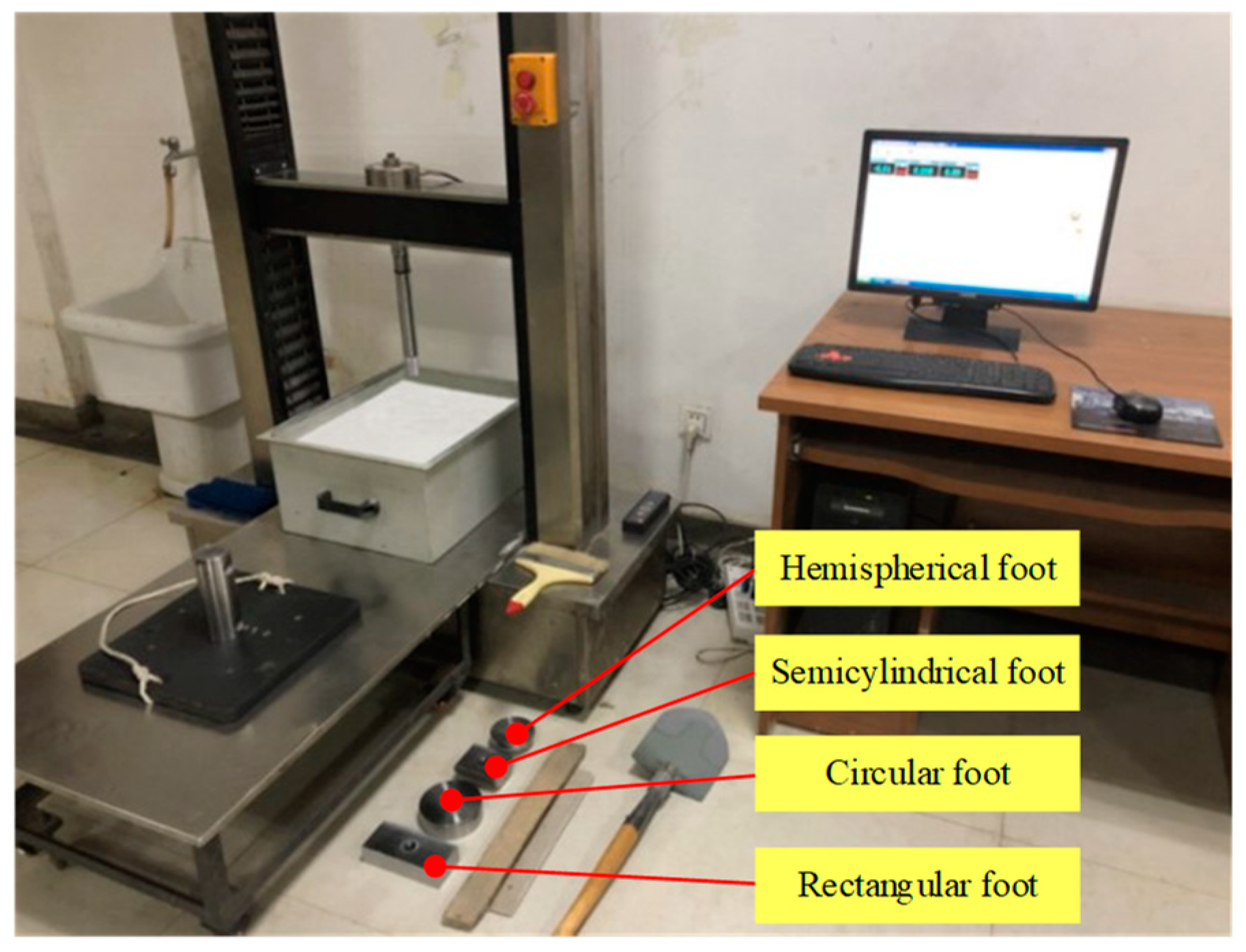
Han from Jilin University designed and manufactured four typical structures of feet, namely hemispherical feet, semi-cylindrical feet, rectangular feet, and circular feet. Research has been conducted on how the size, shape, and density of quartz sand particles affect the matrix’s physical characteristics and the mechanical performance of foot penetration. On the three types of quartz sand, the intrusion resistance and pressure of the hemispherical feet are lower than those of the other three mechanical feet. It was found that as the particle size of quartz sand increases, the invasion resistance of the mechanical foot first increases and then decreases. The revised model has been obtained [92]. The corrected integral equations are shown in Table 3. The mechanical feet and intrusion testing equipment are shown in Figure 31.
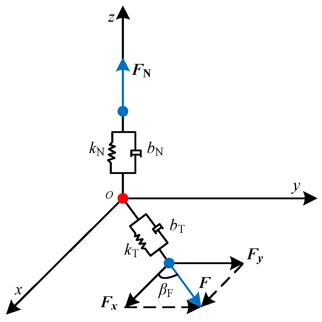
Furthermore, Ding posited that in the normal direction, the interaction force typically resembles the force exerted on a spring and damper located at the foot. The spring damping model shows the interaction between the robot’s foot and the terrain in the normal direction [93]. The foot–terrain interaction in the normal direction is shown in Figure 32. The mathematical model of spring damping can be shown in Equation (15). Then
F N = F FN = F TN m F g + m F δ ¨ T
where FTN is the normal force exerted by the terrain on the foot. mF is the mass of the foot. δT and δF represent the deformation of the terrain and feet, and δ is the sum of them.
If the damping is ignored and the spring is linear, the mathematical model of the normal force can be shown in Equation (16). Then
F N = k FN δ F = k TN δ T
where kFN is the normal stiffness coefficient of the foot. kTN is the normal stiffness coefficient of the terrain.
When δ = δ F + δ T = F N / k FN + F N / k TN , the equivalent equation for the mechanics of foot–terrain contact can be rewritten as follows:
F N = δ 1 / k FN + 1 / k TN
When a legged robot is in motion, the normal load on the foot is not constant. During the process of contact between the foot and the terrain, the deformation of the terrain and the speed of the foot are also in a state of change. Gao believes that during the foot–terrain interaction, the foot tip may shift multiple times and come into contact with the terrain again, including before contact, contact, departure, and recontact [94]. The first contact process can be represented by the Hunt–Crossley model, while the second contact process can be represented by an improved model. The improved model of normal force can be obtained and shown in Equation (18). Ding and Gao’s research lays the foundation for improving the terrain stability of the heavy-duty hexapod robot ELSpider. The outdoor experiment of the robot on the interaction between the robot foot and the terrain is shown in Figure 33. Then
F N = k N δ δ ¯ n 1 + C N δ ˙ m δ δ ¯ n 2     δ > δ ¯ 0           δ δ ¯
In light of the static force’s continuity, an additional limitation is presented in Equation (19). Then
k N δ max n 1 = k N δ max δ ¯ n 1
However, considering the dynamic parameters of the robot’s foot and the ultimate bearing capacity of the terrain, Yang [95] proposed a dynamic bearing capacity model. The model serves as a crucial indicator for determining the normal force boundary conditions essential for the interaction between the foot and the soft terrain. The dynamic bearing capacity model is shown in Equation (20). Then
F N = i = 1 n σ m i A i cos α i
where σ m i is the revised dynamic bearing capacity. A is the area of the foot.
The zero slip pressure–sinkage models applied to the wheeled robots, the wheel-legged robots, and the legged robots are summarized. The zero slip pressure–sinkage models provided in the literature are shown in Table 4.

3.1.2. Models for Pressure–Sinkage at Non-Zero Slip Conditions

When the robot’s foot slides on the terrain, a tangential force perpendicular to the normal pressure direction is generated. The tangential force can lead to tangential deformation, causing lateral soil loss and resulting in slip sinkage. Therefore, adding very little cohesive moist sandy soil to hard soil can also reduce slip sinkage. Reece discovered that the sinkage occurring when the robot is functioning on soil with non-zero slip can be described as a combination of static sinkage and sliding sinkage. The soil deformation model is shown in Equation (21). Then
z = z o + z j
where zo represents static sinkage, and zj represents dynamic sinkage.
The model for predicting soil sliding was proposed by Reece [86]. The Reece prediction model is shown in Equation (22). Then
z = z o + h gr i / 1 i
where hgr is the grouser height, and i is the slip ratio.
A new non-zero slip model was studied by Vasilev. This model can be used to represent the relationship between pressure and settlement [96]. The Vasilev model is shown in Equation (23). Then
z = z o + i H p
where Hp is the propagation depth of soil deformation that can only be evaluated through experiments.
Yeomans [97] considered the phenomenon of foot sinkage in the normal direction due to rotation. Through experimental verification of the hemispherical foot of the planetary exploration robot CREX, a semi-empirical formula for sinkage, rotation direction angle, and normal stress was established. The outdoor experiment of CREX and the rotating sinkage experimental device are shown in Figure 34. The lateral sinkage characteristics can be well described by Equation (24). Then
h lateral = A 1 exp B s l i p
The rotational sinkage behavior can be described by Equation (25). Then
Sin kage = K Stress footradius 2 1 e B θ
Overall, compared to the wheels of wheeled robots, the foot of the legged robot does not produce a significant rotation angle. Compared with zero slip, the pressure and sinkage caused by non-zero slip are smaller. When analyzing the normal force of heavy-duty legged robots, it is generally believed that the slip amount of foot sinkage is relatively small.

3.2. Tangential Force Models

The aim of integrating tangential interaction models is to illustrate that the shear displacement of the foot on the terrain induces an effect on the tangential plane. In traditional contact models, models that separately describe tangential forces often consider normal force and tangential relative motion position as common determining factors [98]. The heavy-duty legged robots generate tangential friction when performing the tangential relative motion.
In terms of the tangential mechanical models of the foot, the most classic tangential friction model is the Coulomb model [99,100]. As a static friction theory, the Coulomb model has a small computational complexity. Its mechanical parameters are easy to identify. The Coulomb model has been widely used [101,102]. The Coulomb model is shown in Equation (26). Then
F = F C + F S F C e v / v S δ S + F v       if   v 0 F e   if   v 0 and F e < F S F S sgn F e   otherwise
The Hunt–Crossley model also describes the action model of tangential force, as shown in Equation (27). Then
F T t = f × sign v T × F N t C t × v T t
In the study of terrain mechanics, the spring damping system has been widely used in foot–terrain interactions. Liang [103] validated that a simple spring damping system can explain the characteristics of human walking by establishing models and conducting experiments. Conventional 3D models segment the deformation of feet or terrain into two perpendicular directions on a tangential plane, specifically the x and y axes. Significant errors are generated because the coupling effect of deformation is ignored.
In order to consider the coupling effect, Ding [93] proposed a new three-dimensional mechanical model of the foot–terrain interaction in combination with a spring damping system. The three-dimensional interaction mechanical model on a tangential plane is shown in Figure 35. The three-dimensional mechanical model of the foot–terrain interaction can be shown in Equation (28). Then
F z = F N F x = F T cos β F F y = F T sin β F
The process of tangential interaction can also be seen as a normal interaction. As the foot slides across the terrain, the tangential force escalates in correspondence with the rising shear displacement and velocity. The tangential force quickly stabilizes as the shear speed decreases to a certain value. Contrary to the previous growth process, the tangential force suddenly drops to zero when the foot moves in the opposite direction.
The force in a specific tangent direction is usually represented by the Coulomb friction model. If the terrain is relatively hard, the tangential force model uses a modified form. When the direction of relative motion velocity changes, the friction force remains unchanged and does not meet the physical boundary conditions of the friction process, resulting in singular solutions in the simulation. When introducing the hyperbolic tangent function to establish a foot–terrain tangential force model, the value of th(δ) is infinitely close to 1 or -1 to describe the saturation of tangential friction. The foot–terrain interaction in the tangent direction is shown in Figure 36. The hyperbolic tangent mathematical model is shown in Equation (29). Then
t h δ = s h δ c h δ = e δ e δ e δ + e δ
For deformed soil [85], a modified model based on the Janosi equation is proposed; it can be shown in Equation (30). Then
F r = exp s / K exp s / K exp s / K + exp s / K μ f F N K = 1.5 K
where s is the shearing displacement. K is the shear displacement modulus, affected by the physical characteristics of the feet and terrain. μf is the friction coefficient between hard terrain and foot materials. For deformable terrain, μf is related to the characteristics of the soil and feet.
However, when applying the new three-dimensional mechanical model to practical simulations, there is a lack of consideration for the damping effect between the feet and the terrain. The model is unstable when the feet interact dynamically with the terrain. Consequently, the force of interaction along the tangent direction is altered when the foot proceeds in a unidirectional movement. The interaction force in the tangent direction is shown in Equation (31). Then
F r = exp s / K exp s / K exp s / K + exp s / K μ f F N c T s ˙ s 0 < s < s max κ
where μf is the friction coefficient. cT is the tangential damping coefficient.
The suggested models are developed across three distinct categories: a flexible foot interacting with rigid terrain, a rigid foot on pliable terrain, and a flexible foot engaging with deformable terrain. The model proposes different mechanical models based on the geometric characteristics of different feet, which can accurately characterize the mechanical conditions of the feet in practical applications. The foot–terrain mechanics model parameters are shown in Table 5. An SVM method is proposed that uses two specific tactile movements of the heavy-duty legged robots to extract physical information features for effective terrain classification. Through the normal compression and tangential friction motion of legged robots, the representative interactive data is obtained to characterize the terrain features [104], which plays an important role in improving the accuracy of the model.
Yang fully considers the shape characteristics of the contact surface and slip surface under the assumptions of some classical soil mechanics for the limit-bearing theory. The normal and the tangential mechanical models of flat foot and sand, horizontal strip foot and sand, circular and sand, and rectangular flat foot and sand, as well as the interaction model of curved foot and sand, have been established [105]. It has a positive effect on calculating the foot mechanics of robots with different shapes. The tangential force models are shown in Table 6.
The terrain mechanics models can establish a close connection between the parameters in soil mechanics and the foot contact mechanics of the robots. It is convenient to conduct a mechanical analysis of the foot–terrain interaction of the heavy-duty legged robots. However, there is still a long way to go in the research of foot–terrain mechanics for heavy-duty legged robots.

4. Further Research

The terrain mechanics characteristics are an effective supplement to the geometric characteristics of terrain. Taking into account the geometric and mechanical characteristics of the terrain comprehensively is an inevitable way to improve the adaptability of the heavy-duty legged robots to unstructured environments. There are still some issues that need further research regarding the mechanical behavior of terrain interaction for heavy-duty legged robots.

4.1. Configuration Research of Biomimetic Supporting Feet

4.1.1. Application of Bionic Technology in Supporting Feet Design

The common supporting feet of heavy-duty legged robots are feet with passive adaptive joints. Although there are currently cylindrical, spherical, rectangular, and other configurations, there is still a lack of feet that can be used for heavy-duty legged robots in the vast majority of scenarios. In further research, the feet design of the heavy-duty legged robots can adopt biomimetic technology. Biomimetic technology can help expand the application fields of heavy-duty legged robots. The feet of large legged animals in nature can be adopted, as shown in Figure 37. The characteristics and biomimetic design elements of the large legged animals’ feet can be shown in Table 7.

4.1.2. Design and Distribution of Plantar Patterns of Supporting Feet

The plantar patterns of the heavy-duty legged robots also affect the process of foot–terrain mechanics. Therefore, it is essential to design plantar patterns for heavy-duty legged robots. The pattern shapes with better anti-slip performance need to be designed. Based on the previous research, the performance of the multi-baffle foot is good. A biomimetic foot plantar pattern with multi-directional braking stability is designed. The rubber plantar pattern can be fixed by bolts in grooves at the same latitude as the flat and spherical robot feet. The foot plantar pattern cannot undergo significant displacement after installation in the above way, as shown in Figure 38.
The direct contact between human feet and terrain is skin tissue, which also contains a large amount of adipose tissue on the inner side. The rubber foot plantar pattern consists of the upper, middle, and lower layers. The middle layer adopts a multi-baffle structure of biomimetic mesh fiber membrane. The rectangular gap in the middle of the baffle is filled with biomimetic adipose tissue.

4.2. Study of Effective Contact Area between Irregular Foot and Dynamic Deformable Terrain

The existing classical theories of pressure–sinkage do not include actual area parameters, as the area of the tested object in classical mechanical models is considered regular. Some robots carry patterns on their feet, and for different surfaces, it is not possible to calculate the actual contact area by substituting the total area of the foot contour into the model. K is considered as the ratio of the actual touchdown area to the outer contour area. In the design process of the model, determining the size of the ratio can consider the impact of the actual contact area on the model. ζ is the terrain coefficient affected by different mechanical properties. Its value is closest to 1 in muddy terrain, second in soft terrain, and smallest in hard terrain. The area evaluation mathematical model can be shown in Equation (32).
Then
K = ζ S 0 S
where K is the ratio of the actual touchdown area to the outer contour area. ζ is the terrain coefficient affected by the different mechanical properties, and its value ranges from 0 to 1. S0 is the actual contact area. S is the outer contour area.
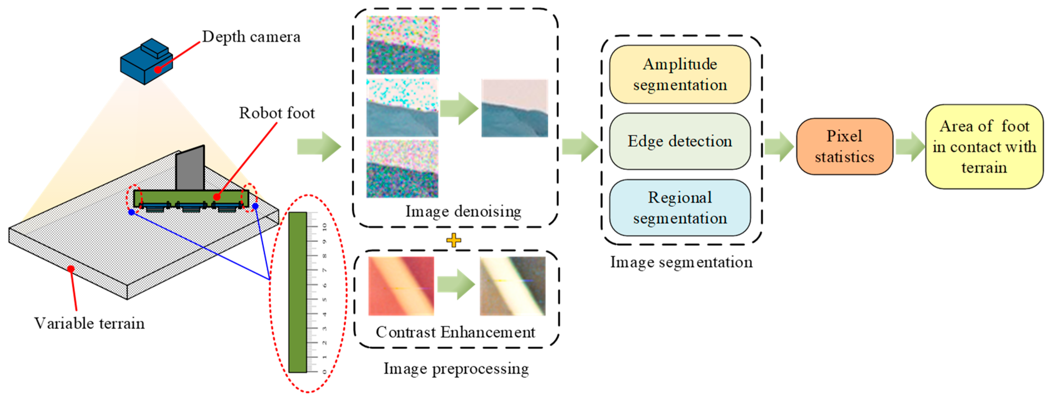
The actual contact area is obtained by capturing images of the foot’s contact with the terrain using a depth camera. The images are analyzed to measure the actual contact area by using computer vision techniques. The two sides of the robot’s feet are equipped with the dividing rules to estimate the depth of sinkage. A depth camera is installed underneath the robot’s foot to capture images of the foot’s contact area with the terrain. The captured images undergo preprocessing to remove the noise, enhance the contrast, and improve the clarity. Image segmentation techniques are employed to separate the foot from the terrain in the images. In the segmented images, the contact area between the foot and the terrain can be detected and measured by counting pixels or using image processing libraries. Finally, the calibration is performed to relate the pixels in the images to the real-world physical dimensions based on the camera’s parameters and the robot’s position. The measurement of the actual contact area between the foot and the terrain is shown in Figure 39.

4.3. Mechanical Behavior Modeling of Interaction between Supporting Feet and Extreme/Dynamic Environments

4.3.1. Construction of Nonlinear Tangential Force Mathematical Model

The tangential force models involving the heavy-duty legged robots still lack coefficients related to the material of the foot. Considering the effects of contact area, terrain, foot material, included angle, and displacement, a nonlinear mathematical model of tangential force is obtained, as shown in Equation (33). Then
F T = F T S 0 , N 1 , N 2 , θ , φ , k , j
where S0 is the actual contact area, N1 is the parameter related to the material of the foot, N2 is the parameter related to terrain properties, θ is the angle between the foot and the terrain, φ is the friction angle inside the soil, k is the soil shear modulus, and j is the soil shear displacement.
It is necessary to include material performance parameters of the foot in the foot–terrain mechanics models. Hardness is the ability of the material to resist scratches and deformation, usually related to the frictional properties of the terrain. Strength is the ability of the material to resist fracture or deformation. Robot feet need sufficient strength to withstand the weight of the robot and external impact forces. The elastic modulus represents the elastic deformation ability of the material after being subjected to force. For the foot, an appropriate elastic modulus can provide the elasticity and shock absorption performance of the foot. Wear resistance refers to the ability of the material to withstand friction or wear conditions. The friction coefficient represents the friction performance between the material for robot feet and other surfaces. The robot foot needs an appropriate coefficient of friction to ensure stable terrain adhesion and movement.

4.3.2. Construction of Resultant Force Mathematical Model

The six-dimension force sensors are typically installed on the feet of the heavy-duty legged robots. The forces and moments in three directions are measured. When a robot travels on a slope, the proportion of normal and tangential forces acting on its foot in the resultant force is different. The difference in proportion is significant at a certain moment. Therefore, in model design, u is considered as the ratio of tangential force to normal force, as shown in Equation (34). A mathematical model for evaluating the resultant force on the foot is derived, as shown in Equation (35). Then
u = F T / F N
F = F N u < 0.1 F T u > 0.9 F N + tan φ F T 1 exp j / k 0.1 u 0.9

4.4. Parameterization Research of Soil Characteristics in Extreme/Dynamic Environments

The foot–terrain interaction behavior involves the configuration of feet and the dynamic terrain characteristics. In the future, in addition to optimizing the structural design of the foot, the various indicators of different soils can also be studied. Clarifying the properties of soil in an unstructured environment will be more conducive to the research on the mechanical properties of heavy-duty legged robots. The performance parameters of different soils on Earth are shown in Table 8.
The composition of Martian soil includes many complex organic compounds. The composition and performance vary from location to location [107,108,109]. Due to the limitations of rocket launch loads, current Mars rovers do not carry dedicated equipment for measuring the mechanical parameters of Martian soil, making it impossible to accurately obtain the mechanical parameters of Martian soil in real time. According to the theory of vehicle terrain mechanics and the mathematical models of the wheel–soil interaction, the mechanical parameters of the Martian soil under the wheel and around the rover can be identified. The Viking probe mainly includes two landers: Viking 1 and Viking 2 [110]. Viking 1 landed on the Chryse Planitia (22.48° N, 49.97° W) on 20 July 1976, and Viking 2 landed on the Utopia Planitia (47.97° N, 225.74° W) on 3 September 1976. The mechanical performance evaluation of the weathered materials at Viking 1 and Viking 2 landing sites is shown in Table 9. The captured images are shown in Figure 40. The properties of the Martian soil are indispensable for studying foot–terrain mechanical models in the Martian environment.
On the surface of the moon, due to the impact of meteorites and micro-meteorites, continuous bombardment by cosmic rays, solar wind, and changes in temperature differences between day and night, the lunar rocks undergo thermal expansion, contraction, and fragmentation, resulting in the formation of lunar soil with an average thickness of approximately 6–10 m. In addition, the lunar environment, which is completely different from that on Earth, such as anhydrous and biotic environments, low gravity, and almost zero atmospheric pressure, also results in significant differences in the physical and mechanical properties of lunar soil and Earth’s soil [112].
Currently, the analysis of various physical parameters and mechanical properties of lunar soil mainly relies on two methods: in situ return and in situ detection. In situ detection is mainly achieved using uncrewed detection equipment. Many scholars aim to identify the mechanical parameters of lunar soil by studying the interaction between planetary detection wheels and sampling robotic arms with lunar soil. The mechanical parameters of lunar soil published by Lunar Sourcebook have been widely recognized [113], as shown in Table 10. The soil density is mainly obtained from density tests of samples retrieved from previous Apollo missions (US lunar landing program). The density of lunar soil is the accumulated mass of granular materials per unit volume in their natural state. The monthly soil density ranges of Apollo 11, 12, 14, 15, and 16, and Luna 16 and 20 are shown in Table 11. Other detailed physical and mechanical properties of lunar soil can be found in the literature [114].
The density of the lunar soil can be acquired using Equation (36). Then
ρ = m v s + v r
where ρ is the bulk density, m is the total mass of lunar soil, vs is the solid volume of lunar soil particles, and vr is the pore volume of lunar soil particles.

4.5. Cross-Application of Multimodal Information Fusion and Foot–Terrain Interaction Mechanics

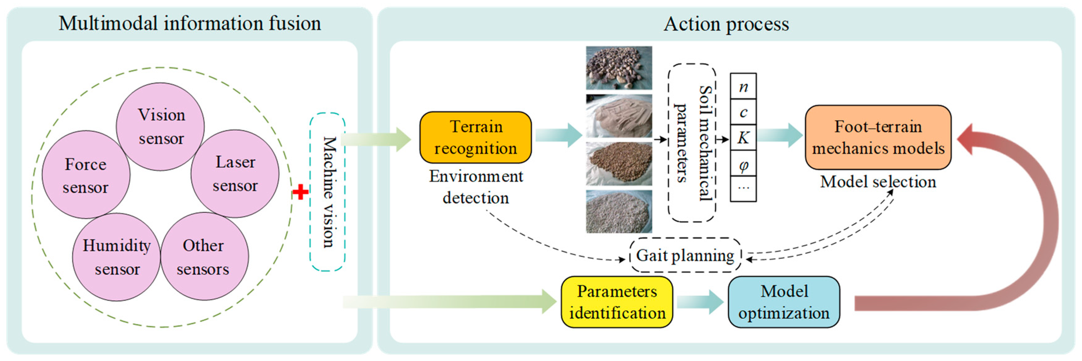
When heavy-duty legged robots are not equipped with effective sensing systems, the unstructured terrain features cannot be adequately extracted and analyzed. Then, the fundamental information of sufficient force distribution would be lacking, which would result in many uncertainties during the walking process of the heavy-duty legged robots. Based on the multimodal information fusion technologies, the appropriate mechanical models of the heavy-duty legged robots can be effectively selected through the analysis and extraction of the terrain information, which is helpful for the robot to complete the gait switching and reduce the danger of navigation in unknown environments. In addition, the combination of multi-sensor fusion and machine vision technology can effectively identify the model parameters and improve their accuracy. Thus, the cross-application of the multimodal information fusion and foot–terrain interaction mechanics would play an important role in the mechanical model selection. The process of choosing the appropriate mechanical model to use the multimodal information fusion is shown in Figure 41.

5. Conclusions

(1) The factors influencing the terrain adaptability of the heavy-duty legged robots are explored. Various foot shapes, including cylindrical, semi-cylindrical, spherical, hemispherical, square, and special configurations, are examined, each presenting distinct advantages and disadvantages. When designing the mechanical structure of a robot, the selection of foot configurations and the design of appropriate foot patterns, tailored to specific needs, prove beneficial in enhancing the robot’s adaptability to unstructured environments and improving its overall mobility. However, challenges persist as heavy-duty legged robots’ feet encounter difficulties adapting to certain unstructured surfaces. Common terrains such as deserts, uneven lunar surfaces, and areas containing stones pose particular challenges for heavy-duty legged robots. Addressing these challenges will be crucial in further refining the design of heavy-duty legged robots for diverse terrains.
(2) The ultimate goal is to design feet for heavy-duty legged robots with enhanced anti-sinkage capabilities, increased traction, and a lightweight structure. To augment the terrain adaptability of heavy-duty legged robots, insights from the characteristics of large legged animals’ feet have been distilled. Furthermore, the proposed design elements for biomimetic feet aim to emulate nature’s solutions. The incorporation of biomimetic foot plantar patterns onto the sole of the foot proves particularly impactful, substantially amplifying the robot’s adhesion capabilities.
(3) The mechanics of foot–terrain interactions encompass both normal and tangential forces occurring between the foot and the contact terrain. An accurate model detailing the mechanics of foot–terrain interaction plays a crucial role in investigating the terrain adaptability of robots. While research on wheel–terrain interaction models is relatively advanced, there is a noticeable gap in the exploration of mechanical models for foot–terrain interactions. A comprehensive and fully established system for the mechanical model of heavy-duty legged robots’ foot–terrain interactions is yet to be realized. The challenges in terrain mechanics for heavy-duty legged robots necessitate support from a systematic theoretical framework.
(4) To enhance the model’s precision, an area evaluation parameter is introduced. Subsequently, a mathematical model incorporating the interaction between feet and terrain is proposed to calculate the tangential force. The resultant force equation on the robot’s foot is predicted. The mechanical properties of the soil in contact with the foot–terrain interaction significantly influence performance. Investigating various soil parameters for the classification of unstructured terrain holds paramount importance in understanding the mechanics of foot–terrain interactions. Furthermore, exploring the soil on other planets is crucial for the future success of heavy-duty legged robots in interstellar exploration missions. This study includes mechanical performance parameters for real lunar soil, simulated lunar soil, and Martian soil. In future research, the integration of multimodal information fusion and foot–terrain interaction mechanics will be leveraged for cross-application purposes.

Author Contributions

Conceptualization, H.Z.; methodology, H.Z. and J.W.; formal analysis, N.W., W.L., N.L. and L.D.; data curation, H.Z. and J.W.; writing—original draft preparation, H.Z. and J.W.; writing—review and editing, H.Z.; visualization, J.W., N.W. and B.L.; supervision, H.Z.; funding acquisition, H.Z., W.L. and N.W. All authors have read and agreed to the published version of the manuscript.

Funding

This research was supported by the National Natural Science Foundation of China (Grant No. 51505335 and Grant No. 52175007), the Industry University Cooperation Collaborative Education Project of the Department of Higher Education of the Chinese Ministry of Education (Grant No. 202102517001), and the Doctor Startup Project of TUTE (Grant No. KYQD 1806). These supports are greatly acknowledged.

Conflicts of Interest

The authors declare no conflicts of interest.

Nomenclature

AContact areaδSum of foot and terrain deformations
BGeometric parameter of plateλNDimensionless function
bSmaller dimension of contact patchvTTangential sliding velocity
CNNormal damping coefficientδTTerrain deformation
CTTangential damping coefficientδFFeet deformation
CmModel parameter μCoefficient of friction
CfShape coefficient of contact surfaceFNNormal support force
cSoil stickinessFTTangential driving force
αDimensionless geometric constantHpPropagation depth of soil deformation
βDimensionless geometric constanthgrGrouser height
iSlip ratioN1, N2Model parameter
jSoil shear displacementpPressure
kSinkage modulusp0Bearing capacity
kNEquivalent stiffness coefficientsShearing displacement
kFNStiffness coefficient of foots0Model parameter
kTNStiffness coefficient of terrainsmModel parameter
kcSinkage modulusvPoisson’s ratio
kΦSinkage modulusvsSolid volume
kSStiffness modulus of terrainvrPore volume
k1Model parameterwDimensionless coefficient
k2Model parameterzSinkage
mExponent of damping termzoStatic sinkage
mFMass of footzjDynamic sinkage
nModel parameterρBulk density
n1, n2Indicators of stiffness terms

References

  1. Zhuang, H.; Gao, H.; Deng, Z.; Ding, L.; Liu, Z. A review of heavy-duty legged robots. Sci. China Technol. Sci. 2014, 57, 298–314. [Google Scholar] [CrossRef]
  2. Biswal, P.; Mohanty, P.K. Development of quadruped walking robots: A review. Ain Shams Eng. J. 2021, 12, 2017–2031. [Google Scholar] [CrossRef]
  3. Maity, A.; Majumder, S.; Ghosh, S. An experimental hyper redundant serpentine robot. In Proceedings of the 2010 IEEE International Conference on Systems, Man and Cybernetics—SMC, Istanbul, Turkey, 10–13 October 2010; pp. 3180–3185. [Google Scholar] [CrossRef]
  4. Joshi, V.A.; Banavar, R.N.; Hippalgaonkar, R. Design and analysis of a spherical mobile robot. Mech. Mach. Theory 2010, 45, 130–136. [Google Scholar] [CrossRef]
  5. Bartsch, S.; Manz, M.; Kampmann, P.; Dettmann, A.; Hanff, H.; Langosz, M.; von Szadkowski, K.; Hilljegerdes, J.; Simnofske, M.; Kloss, P.; et al. Development and Control of the Multi-Legged Robot MANTIS. In Proceedings of the ISR 2016: 47st International Symposium on Robotics, Munich, Germany, 21–22 June 2016; pp. 1–8. [Google Scholar]
  6. Cobano, J.; Ponticelli, R.; de Santos, P.G. Mobile robotic system for detection and location of antipersonnel land mines: Field tests. Ind. Robot. Int. J. Robot. Res. Appl. 2008, 35, 520–527. [Google Scholar] [CrossRef]
  7. Carbone, G.; Ceccarelli, M. Legged Robotic Systems; Intech Open Access Publisher: London, UK, 2005. [Google Scholar]
  8. Zhang, Q.; Zhao, W.; Chu, S.; Wang, L.; Fu, J.; Yang, J.; Gao, B. Research Progress of Nuclear Emergency Response Robot. IOP Conf. Ser. Mater. Sci. Eng. 2018, 452, 042102. [Google Scholar] [CrossRef]
  9. Zhuang, H.C.; Wang, N.; Gao, H.B.; Deng, Z.Q. Autonomous fault-tolerant gait planning research for electrically driven large-load-ratio six-legged robot. In Proceedings of the 12th International Conference on Intelligent Robotics and Applications (ICIRA 2019), Shenyang, China, 8–11 August 2019; pp. 231–244. [Google Scholar] [CrossRef]
  10. Zhuang, H.-C.; Gao, H.-B.; Deng, Z.-Q. Gait Planning Research for an Electrically Driven Large-Load-Ratio Six-Legged Robot. Appl. Sci. 2017, 7, 296. [Google Scholar] [CrossRef]
  11. Zhuang, H.-C.; Gao, H.-B.; Deng, Z.-Q. Analysis Method of Articulated Torque of Heavy-Duty Six-Legged Robot under Its Quadrangular Gait. Appl. Sci. 2016, 6, 323. [Google Scholar] [CrossRef]
  12. Bloesch, M.; Gehring, C.; Fankhauser, P.; Hutter, M.; Hoepflinger, M.A.; Siegwart, R. State estimation for legged robots on unstable and slippery terrain. In Proceedings of the 2013 IEEE/RSJ International Conference on Intelligent Robots and Systems (IROS 2013), Tokyo, Japan, 3–7 November 2013; pp. 6058–6064. [Google Scholar] [CrossRef]
  13. Voloshina, A.S.; Kuo, A.D.; Ferris, D.P.; Remy, D.C. A model-based analysis of the mechanical cost of walking on uneven terrain. bioRxiv 2020. [Google Scholar] [CrossRef]
  14. Zhuang, H.; Xia, Y.; Wang, N.; Li, W.; Dong, L.; Li, B. Interactive method research of dual mode information coordination integration for astronaut gesture and eye movement signals based on hybrid model. Sci. China Technol. Sci. 2023, 66, 1717–1733. [Google Scholar] [CrossRef] [PubMed]
  15. Saraiva, L.; da Silva, M.R.; Marques, F.; da Silva, M.T.; Flores, P. A review on foot-ground contact modeling strategies for human motion analysis. Mech. Mach. Theory 2022, 177, 105046. [Google Scholar] [CrossRef]
  16. Hodoshima, R.; Doi, T.; Fukuda, Y.; Hirose, S.; Okamoto, T.; Mori, J. Development of a Quadruped Walking Robot TITAN XI for Steep Slope Operation—Step Over Gait to Avoid Concrete Frames on Steep Slopes. J. Robot. Mechatron. 2007, 19, 13–26. [Google Scholar] [CrossRef]
  17. Hirose, S.; Yokota, S.; Torii, A.; Ogata, M.; Suganuma, S.; Takita, K.; Kato, K. Quadruped Walking Robot Centered Demining System—Development of TITAN-IX and its Operation. In Proceedings of the 2005 IEEE International Conference on Robotics and Automation, Barcelona, Spain, 18–22 April 2005; pp. 1284–1290. [Google Scholar] [CrossRef]
  18. Hirose, S.; Fukuda, Y.; Kikuchi, H. The gait control system of a quadruped walking vehicle. Adv. Robot. 1986, 1, 289–323. [Google Scholar] [CrossRef]
  19. Irawan, A.; Nonami, K. Compliant Walking Control for Hydraulic Driven Hexapod Robot on Rough Terrain. J. Robot. Mechatronics 2011, 23, 149–162. [Google Scholar] [CrossRef]
  20. Bares, J.E.; Wettergreen, D.S. Dante II: Technical Description, Results, and Lessons Learned. Int. J. Robot. Res. 1999, 18, 621–649. [Google Scholar] [CrossRef]
  21. A Galvez, J.; Estremera, J.; de Santos, P.G. A new legged-robot configuration for research in force distribution. Mechatronics 2003, 13, 907–932. [Google Scholar] [CrossRef]
  22. Zhuang, H.C. Electrically Driven Large-Load-Ratio Six-Legged Robot Structural Design and Its Mobile Characteristics Research. Ph.D. Dissertation, Harbin Institute of Technology, Harbin, China, 2014. (In Chinese). [Google Scholar]
  23. Zhuang, H.; Wang, N.; Gao, H.; Deng, Z. Quickly Obtaining Range of Articulated Rotating Speed for Electrically Driven Large-Load-Ratio Six-Legged Robot Based on Maximum Walking Speed Method. IEEE Access 2019, 7, 29453–29470. [Google Scholar] [CrossRef]
  24. Liu, Y.; Ding, L.; Gao, H.; Liu, G.; Deng, Z.; Yu, H. Efficient force distribution algorithm for hexapod robot walking on uneven terrain. In Proceedings of the 2016 IEEE International Conference on Robotics and Biomimetics (ROBIO), Qingdao, China, 3–7 December 2016; pp. 432–437. [Google Scholar] [CrossRef]
  25. Xu, P.; Ding, L.; Li, Z.; Yang, H.; Wang, Z.; Gao, H.; Zhou, R.; Su, Y.; Deng, Z.; Huang, Y. Learning physical characteristics like animals for legged robots. Natl. Sci. Rev. 2023, 10, nwad045. [Google Scholar] [CrossRef]
  26. Pan, Y.; Gao, F. A new six-parallel-legged walking robot for drilling holes on the fuselage. Proc. Inst. Mech. Eng. Part C J. Mech. Eng. Sci. 2014, 228, 753–764. [Google Scholar] [CrossRef]
  27. Yang, P.; Gao, F. Kinematical Model and Topology Patterns of a New 6-Parallel-Legged Walking Robot. In Proceedings of the ASME 2012 International Design Engineering Technical Conferences and Computers and Information in Engineering Conference, Volume 4: 36th Mechanisms and Robotics Conference, Parts A and B, Chicago, IL, USA, 12–15 August 2012; pp. 1197–1205. [Google Scholar] [CrossRef]
  28. Pan, Y.; Gao, F. Payload capability analysis of a new kind of parallel leg hexapod walking robot. In Proceedings of the 2013 International Conference on Advanced Mechatronic Systems (ICAMechS), Luoyang, China, 25–27 September 2013; pp. 541–544. [Google Scholar] [CrossRef]
  29. Yang, P.; Gao, F. Leg kinematic analysis and prototype experiments of walking-operating multifunctional hexapod robot. Proc. Inst. Mech. Eng. Part C J. Mech. Eng. Sci. 2013, 228, 2217–2232. [Google Scholar] [CrossRef]
  30. Zhang, H.Y. Analysis of the Structure and Stability of a Large and Highly Adaptable Hexapod Robot. Master’s Thesis, Jilin University, Changchun, China, 2021. (In Chinese). [Google Scholar]
  31. Zhai, C. Research on Motion Trajectory Planning of Heavy-Load Hydraulic Driven Hexapod Robots. Master’s Thesis, Jilin University, Changchun, China, 2023. (In Chinese). [Google Scholar]
  32. Gao, J. Leg Mechanism Design and Simulation Analysis for a Heavy-Duty Hydraulic Hexapod Robot. Master’s Thesis, Jilin University, Changchun, China, 2017. (In Chinese). [Google Scholar]
  33. Xu, Z.; Yi, H.; Liu, D.; Zhang, R.; Luo, X. Design a Hybrid Energy-Supply for the Electrically Driven Heavy-Duty Hexapod Vehicle. J. Bionic Eng. 2023, 20, 1434–1448. [Google Scholar] [CrossRef]
  34. Xu, Z.; Chen, X.; Liu, Y.; Wang, L.; Zhou, L.; Yi, H.; Bao, C. Design and Implementation of a Novel Robot Foot with High-adaptability and High-adhesion for Heavy-load Walking Robots. In Proceedings of the 2019 IEEE 9th Annual International Conference on CYBER Technology in Automation, Control, and Intelligent Systems (CYBER), Suzhou, China, 29 July–2 August 2019; pp. 1509–1514. [Google Scholar] [CrossRef]
  35. Raibert, M.; Blankespoor, K.; Nelson, G.; Playter, R. BigDog, the rough-terrain quadruped robot. IFAC Proc. Vol. 2008, 41, 10822–10825. [Google Scholar] [CrossRef]
  36. Wooden, D.; Malchano, M.; Blankespoor, K.; Howardy, A.; Rizzi, A.A.; Raibert, M. Autonomous navigation for BigDog. In Proceedings of the 2010 IEEE International Conference on Robotics and Automation (ICRA 2010), Anchorage, AK, USA, 3–7 May 2010; pp. 4736–4741. [Google Scholar] [CrossRef]
  37. Meng, X.; Wang, S.; Cao, Z.; Zhang, L. A review of quadruped robots and environment perception. In Proceedings of the IEEE 35th Control Conference (CCC), Chengdu, China, 27–29 July 2016; pp. 6350–6356. [Google Scholar] [CrossRef]
  38. Zang, H.; Zhao, D.; Shen, L. Theoretical Study of Global Scale Analysis Method for Agile Bionic Leg Mechanism. Robotica 2020, 38, 427–441. [Google Scholar] [CrossRef]
  39. Han, B.; Yi, H.; Xu, Z.; Yang, X.; Luo, X. 3D-SLIP model based dynamic stability strategy for legged robots with impact disturbance rejection. Sci. Rep. 2022, 12, 5892. [Google Scholar] [CrossRef]
  40. Zhong, J.F. Design, Control of Hydraulical Actuators for Quadruped Legged Robot. Master’s Thesis, Huazhong University of Science and Technology, Wuhan, China, 2014. (In Chinese). [Google Scholar]
  41. Cheng, P. Research, Design of Control System for Bionic Quadruped Robot. Master’s Thesis, Huazhong University of Science and Technology, Wuhan, China, 2014. (In Chinese). [Google Scholar]
  42. Qi, C.; Gao, F.; Sun, Q.; Chen, X.; Xu, Y.; Zhao, X. A foot force sensing approach for a legged walking robot using the motor current. In Proceedings of the 2015 IEEE International Conference on Robotics and Biomimetics (ROBIO), Zhuhai, China, 6–9 December 2015; pp. 1078–1083. [Google Scholar] [CrossRef]
  43. Sun, Q.; Gao, F.; Chen, X. Towards dynamic alternating tripod trotting of a pony-sized hexapod robot for disaster rescuing based on multi-modal impedance control. Robotica 2018, 36, 1048–1076. [Google Scholar] [CrossRef]
  44. Qiao, S. Design, Dynamic Gait Control of the Rescue Hexapod Robot with Erect Posture and Parallel Mechanism Leg. Ph.D. Dissertation, Shanghai Jiaotong University, Shanghai, China, 2018. (In Chinese). [Google Scholar]
  45. Michael, K. Meet Boston Dynamics’ LS3—The Latest Robotic War Machine; University of Wollongong: Wollongong, NSW, Australia, 2012. [Google Scholar]
  46. Rong, X.; Li, Y.; Ruan, J.; Li, B. Design and simulation for a hydraulic actuated quadruped robot. J. Mech. Sci. Technol. 2012, 26, 1171–1177. [Google Scholar] [CrossRef]
  47. Chen, T.; Rong, X.; Li, Y.; Ding, C.; Chai, H.; Zhou, L. A compliant control method for robust trot motion of hydraulic actuated quadruped robot. Int. J. Adv. Robot. Syst. 2018, 15, 1729881418813235. [Google Scholar] [CrossRef]
  48. Yang, K.; Zhou, L.; Rong, X.; Li, Y. Onboard hydraulic system controller design for quadruped robot driven by gasoline engine. Mechatronics 2018, 52, 36–48. [Google Scholar] [CrossRef]
  49. Bartsch, S.; Birnschein, T.; Cordes, F.; Kuehn, D.; Kampmann, P.; Hilljegerdes, J.; Planthaber, S.; Roemmermann, M.; Kirchner, F. Spaceclimber: Development of a six-legged climbing robot for space exploration. In Proceedings of the ISR 2010 (41st International Symposium on Robotics) and ROBOTIK 2010 (6th German Conference on Robotics), Munich, Germany, 7–9 June 2010; pp. 1–8. [Google Scholar]
  50. Bartsch, S.; Birnschein, T.; Römmermann, M.; Hilljegerdes, J.; Kühn, D.; Kirchner, F. Development of the six-legged walking and climbing robot SpaceClimber. J. Field Robot. 2012, 29, 506–532. [Google Scholar] [CrossRef]
  51. Kitano, S.; Hirose, S.; Horigome, A.; Endo, G. TITAN-XIII: Sprawling-type quadruped robot with ability of fast and energy-efficient walking. ROBOMECH J. 2016, 3, 8. [Google Scholar] [CrossRef]
  52. Ohtsuka, S.; Endo, G.; Fukushima, E.F.; Hirose, S. Development of terrain adaptive sole for multi-legged walking robot. In Proceedings of the 2010 IEEE/RSJ International Conference on Intelligent Robots and Systems (IROS 2010), Taipei, Taiwan, 18–22 October 2010; pp. 5354–5359. [Google Scholar] [CrossRef]
  53. Talebi, S.; Poulakakis, I.; Papadopoulos, E.; Buehler, M. Quadruped robot running with a bounding gait. In Experimental Robotics VII; Springer: Berlin/Heidelberg, Germany, 2001; pp. 281–289. [Google Scholar] [CrossRef]
  54. de Santos, P.G.; Cobano, J.; Garcia, E.; Estremera, J.; Armada, M. A six-legged robot-based system for humanitarian demining missions. Mechatronics 2007, 17, 417–430. [Google Scholar] [CrossRef]
  55. Chen, T.; Li, Y.; Rong, X.; Zhang, G.; Chai, H.; Bi, J.; Wang, Q. Design and Control of a Novel Leg-Arm Multiplexing Mobile Operational Hexapod Robot. IEEE Robot. Autom. Lett. 2022, 7, 382–389. [Google Scholar] [CrossRef]
  56. Nelson, G.; Saunders, A.; Neville, N.; Swilling, B.; Bondaryk, J.; Billings, D.; Lee, C.; Playter, R.; Raibert, M. PETMAN: A Humanoid Robot for Testing Chemical Protective Clothing. J. Robot. Soc. Jpn. 2012, 30, 372–377. [Google Scholar] [CrossRef]
  57. Kuindersma, S.; Deits, R.; Fallon, M.; Valenzuela, A.; Dai, H.; Permenter, F.; Koolen, T.; Marion, P.; Tedrake, R. Optimization-based locomotion planning, estimation, and control design for the atlas humanoid robot. Auton. Robot. 2016, 40, 429–455. [Google Scholar] [CrossRef]
  58. Kuehn, D.; Schilling, M.; Stark, T.; Zenzes, M.; Kirchner, F. System Design and Testing of the Hominid Robot Charlie. J. Field Robot. 2017, 34, 666–703. [Google Scholar] [CrossRef]
  59. Fondahl, K.; Kuehn, D.; Beinersdorf, F.; Bernhard, F.; Grimminger, F.; Schilling, M.; Stark, T.; Kirchner, F. An adaptive sensor foot for a bipedal and quadrupedal robot. In Proceedings of the 2012 4th IEEE RAS & EMBS International Conference on Biomedical Robotics and Biomechatronics (BioRob 2012), Rome, Italy, 24–27 June 2012; pp. 270–275. [Google Scholar] [CrossRef]
  60. Mosher, R. Test and evaluation of a versatile walking truck. In Proceedings of the Off-Road Mobility Research Symposium, Washington, DC, USA, 1968; pp. 359–379. [Google Scholar]
  61. Hirose, S.; Yoneda, K.; Tsukagoshi, H. TITAN VII: Quadruped walking and manipulating robot on a steep slope. In Proceedings of the International Conference on Robotics and Automation, Albuquerque, NM, USA, 25 April 1987; pp. 494–500. [Google Scholar] [CrossRef]
  62. He, G.; Xu, J.; Jiang, J.; Cao, Z.; Zhu, D. Soil arching effect analysis and structure optimization of a robot foot sinking in soft soil. Adv. Mech. Eng. 2017, 9, 1687814017727940. [Google Scholar] [CrossRef]
  63. He, G.; Cao, Z.; Li, Q.; Zhu, D.; Aimin, J. Influence of hexapod robot foot shape on sinking considering multibody dynamics. J. Mech. Sci. Technol. 2020, 34, 3823–3831. [Google Scholar] [CrossRef]
  64. Chopra, S.; Tolley, M.T.; Gravish, N. Granular Jamming Feet Enable Improved Foot-Ground Interactions for Robot Mobility on Deformable Ground. IEEE Robot. Autom. Lett. 2020, 5, 3975–3981. [Google Scholar] [CrossRef]
  65. Hong, Y.; Yi, S.; Ryu, S.; Lee, C. Design and experimental test of a new robot foot for a quadrupedal jointed-leg type walking robot. In Proceedings of the 5th IEEE International Workshop on Robot and Human Communication. RO-MAN’96 TSUKUBA, Tsukuba, Japan, 11–14 November 1996; pp. 317–322. [Google Scholar] [CrossRef]
  66. Yamamoto, K.; Sugihara, T.; Nakamura, Y. Toe joint mechanism using parallel four-bar linkage enabling humanlike multiple support at toe pad and toe tip. In Proceedings of the 2007 7th IEEE-RAS International Conference on Humanoid Robots (Humanoids 2007), Pittsburgh, PA, USA, 29 November–1 December 2007; pp. 410–415. [Google Scholar] [CrossRef]
  67. Borovac, B.; Slavnic, S. Design of Multi-segment Humanoid Robot Foot. In Proceedings of the Research and Education in Robotics—EUROBOT 2008: International Conference, Heidelberg, Germany, 22–24 May 2008; pp. 12–18. [Google Scholar] [CrossRef]
  68. Nabulsi, S.; Sarria, J.F.; Montes, H.; Armada, M.A. High-Resolution Indirect Feet–Ground Interaction Measurement for Hydraulic-Legged Robots. IEEE Trans. Instrum. Meas. 2009, 58, 3396–3404. [Google Scholar] [CrossRef]
  69. Collins, S.H.; Kuo, A.D. Recycling Energy to Restore Impaired Ankle Function during Human Walking. PLoS ONE 2010, 5, e9307. [Google Scholar] [CrossRef]
  70. Song, Y. The Analysis and Test of the Robot Foot-Ground Adhesion Properties. Master’s Thesis, Harbin Institute of Technology, Harbin, China, 2014. (In Chinese). [Google Scholar]
  71. Zou, Y.Y. Landing Point Planning and Foot Pattern Design of Hexapod Robot. Master’s Thesis, Dalian University of Technology, Dalian, China, 2019. (In Chinese). [Google Scholar]
  72. Li, J. The Design and Research of Heavy-Duty Robot High Adaptability Foot. Master’s Thesis, Dalian University of Technology, Dalian, China, 2016. (In Chinese). [Google Scholar]
  73. Li, K.W.; Wu, H.H.; Lin, Y.-C. The effect of shoe sole tread groove depth on the friction coefficient with different tread groove widths, floors and contaminants. Appl. Ergon. 2006, 37, 743–748. [Google Scholar] [CrossRef]
  74. Li, K.W.; Chen, C.J.; Lin, C.-H.; Hsu, Y.W. Relationship between measured friction coefficients and two tread groove design parameters for footwear pads. Tsinghua Sci. Technol. 2006, 11, 712–719. [Google Scholar] [CrossRef]
  75. Li, K.W.; Chen, C.J. Effects of tread groove orientation and width of the footwear pads on measured friction coefficients. Saf. Sci. 2005, 43, 391–405. [Google Scholar] [CrossRef]
  76. Irani, R.; Bauer, R.; Warkentin, A. A dynamic terramechanic model for small lightweight vehicles with rigid wheels and grousers operating in sandy soil. J. Terramechanics 2011, 48, 307–318. [Google Scholar] [CrossRef]
  77. Ding, L.; Yang, H.; Gao, H.; Li, N.; Deng, Z.; Guo, J.; Li, N. Terramechanics-based modeling of sinkage and moment for in-situ steering wheels of mobile robots on deformable terrain. Mech. Mach. Theory 2017, 116, 14–33. [Google Scholar] [CrossRef]
  78. Zhuang, H.; Wang, N.; Gao, H.; Deng, Z. Power Consumption Characteristics Research on Mobile System of Electrically Driven Large-Load-Ratio Six-Legged Robot. Chin. J. Mech. Eng. 2023, 36, 26. [Google Scholar] [CrossRef]
  79. Liu, Z.; Zhuang, H.-C.; Gao, H.-B.; Deng, Z.-Q.; Ding, L. Static Force Analysis of Foot of Electrically Driven Heavy-Duty Six-Legged Robot under Tripod Gait. Chin. J. Mech. Eng. 2018, 31, 63. [Google Scholar] [CrossRef]
  80. Bernstein, R. Problems of the experimental mechanics of motor ploughs. Der Motorwagen 1913, 16, 1–10. [Google Scholar]
  81. Saakyan, S.S. Vzaimodeistrie vedomogo kolesa i pochvi. 1959. [Google Scholar]
  82. Comin, F.J.; Saaj, C.M. Models for Slip Estimation and Soft Terrain Characterization with Multilegged Wheel–Legs. IEEE Trans. Robot. 2017, 33, 1438–1452. [Google Scholar] [CrossRef]
  83. Komizunai, S.; Konno, A.; Abiko, S.; Uchiyama, M. Development of a static sinkage model for a biped robot on loose soil. In Proceedings of the 2010 IEEE/SICE International Symposium on System Integration (SII 2010), Sendai, Japan, 21–22 December 2010; pp. 61–66. [Google Scholar] [CrossRef]
  84. Bekker, M.G. Land Locomotion on the Surface of Planets. ARS J. 1962, 32, 1651–1659. [Google Scholar] [CrossRef]
  85. Patel, N.; Scott, G.; Ellery, A. Application of Bekker Theory for Planetary Exploration Through Wheeled, Tracked, and Legged Vehicle Locomotion. In Proceedings of the Space 2004 Conference and Exhibit, San Diego, CA, USA, 28–30 September 2004; p. 6091. [Google Scholar] [CrossRef]
  86. Reece, A.R. Principles of Soil-Vehicle Mechanics. Proc. Inst. Mech. Eng. Automob. Div. 1965, 180, 45–66. [Google Scholar] [CrossRef]
  87. Gotteland, P.; Benoit, O. Sinkage tests for mobility study, modelling and experimental validation. J. Terramechan. 2006, 43, 451–467. [Google Scholar] [CrossRef]
  88. Ding, L.; Gao, H.; Deng, Z.; Li, Y.; Liu, G. New perspective on characterizing pressure–sinkage relationship of terrains for estimating interaction mechanics. J. Terramechan. 2014, 52, 57–76. [Google Scholar] [CrossRef]
  89. Hunt, K.; Crossley, F.R.E. Coefficient of Restitution Interpreted as Damping in Vibroimpact. J. Appl. Mech. 1975, 42, 440–445. [Google Scholar] [CrossRef]
  90. Wheeler, D.D.; Chavez-Clemente, D.; Sunspiral, V.K. FootSpring: A compliance model for the ATHLETE family of robots. In Proceedings of the 10th International Symposium on Artificial Intelligence, Toronto, ON, Canada, 20–21 June 2010. [Google Scholar]
  91. Youssef, A.-F.A.; Ali, G.A. Determination of soil parameters using plate test. J. Terramechan. 1982, 19, 129–147. [Google Scholar] [CrossRef]
  92. Han, D.; Zhang, R.; Zhang, H.; Hu, Z.; Li, J. Mechanical Performances of Typical Robot Feet Intruding into Sands. Energies 2020, 13, 1867. [Google Scholar] [CrossRef]
  93. Ding, L.; Gao, H.; Deng, Z.; Song, J.; Liu, Y.; Liu, G.; Iagnemma, K. Foot–terrain interaction mechanics for legged robots: Modeling and experimental validation. Int. J. Robot. Res. 2013, 32, 1585–1606. [Google Scholar] [CrossRef]
  94. Gao, H.; Jin, M.; Ding, L.; Liu, Y.; Li, W.; Yu, X.; Deng, Z.; Liu, Z. A real-time, high fidelity dynamic simulation platform for hexapod robots on soft terrain. Simul. Model. Pract. Theory 2016, 68, 125–145. [Google Scholar] [CrossRef]
  95. Yang, C.; Ding, L.; Tang, D.; Gao, H.; Deng, Z.; Wang, G. Analysis of the normal bearing capacity of the terrain in case of foot-terrain interaction based on Terzaghi theory. In Proceedings of the 2016 IEEE International Conference on Robotics and Biomimetics (ROBIO), Qingdao, China, 3–7 December 2016; pp. 443–448. [Google Scholar] [CrossRef]
  96. Vasilev, A.V.; Dokychaeva, E.N.; Utkin-Lubovtsov, O.L. Effect of Tracked Tractor Design Parameters on Tractive Performance; Mashinostroenie: Moscow, Russia, 1969.
  97. Yeomans, B.; Saaj, C.M. Towards terrain interaction prediction for bioinspired planetary exploration rovers. Bioinspiration Biomim. 2014, 9, 016009. [Google Scholar] [CrossRef] [PubMed]
  98. Awrejcewicz, J.; Olejnik, P. Analysis of Dynamic Systems with Various Friction Laws. Appl. Mech. Rev. 2005, 58, 389–411. [Google Scholar] [CrossRef]
  99. Olsson, H.; Åström, K.; de Wit, C.C.; Gäfvert, M.; Lischinsky, P. Friction Models and Friction Compensation. Eur. J. Control 1998, 4, 176–195. [Google Scholar] [CrossRef]
  100. Haddadi, A.; Hashtrudi-Zaad, K. A New Method for Online Parameter Estimation of Hunt-Crossley Environment Dynamic Models. In Proceedings of the 2008 IEEE/RSJ International Conference on Intelligent Robots and Systems, Nice, France, 22–26 September 2008; pp. 981–986. [Google Scholar] [CrossRef]
  101. Zapolsky, S.; Drumwright, E. Inverse dynamics with rigid contact and friction. Auton. Robot. 2017, 41, 831–863. [Google Scholar] [CrossRef]
  102. Senoo, T.; Ishikawa, M. Analysis of sliding behavior of a biped robot in centroid acceleration space. Robotica 2017, 35, 636–653. [Google Scholar] [CrossRef]
  103. Liang, H.; Xie, W.; Zhang, Z.; Wei, P.; Cui, C. A Three-Dimensional Mass-Spring Walking Model Could Describe the Ground Reaction Forces. Math. Probl. Eng. 2021, 2021, 6651715. [Google Scholar] [CrossRef]
  104. Ding, L.; Xu, P.; Li, Z.; Zhou, R.; Gao, H.; Deng, Z.; Liu, G. Pressing and Rubbing: Physics-Informed Features Facilitate Haptic Terrain Classification for Legged Robots. IEEE Robot. Autom. Lett. 2022, 7, 5990–5997. [Google Scholar] [CrossRef]
  105. Yang, C.; Ding, L.; Tang, D.; Gao, H.; Niu, L.; Lan, Q.; Li, C.; Deng, Z. Improved Terzaghi-theory-based interaction modeling of rotary robotic locomotors with granular substrates. Mech. Mach. Theory 2020, 152, 103901. [Google Scholar] [CrossRef]
  106. Iagnemma, K.; Kang, S.; Shibly, H.; Dubowsky, S. Online Terrain Parameter Estimation for Wheeled Mobile Robots with Application to Planetary Rovers. IEEE Trans. Robot. 2004, 20, 921–927. [Google Scholar] [CrossRef]
  107. Wu, C. Space exploration: Secrets of the martian soil. Nature 2007, 448, 742–744. [Google Scholar] [CrossRef] [PubMed]
  108. Yen, A.S.; Gellert, R.; Schröder, C.; Morris, R.V.; Bell, J.F.; Knudson, A.T.; Clark, B.C.; Ming, D.W.; Crisp, J.A.; Arvidson, R.E.; et al. An integrated view of the chemistry and mineralogy of martian soils. Nature 2005, 436, 49–54. [Google Scholar] [CrossRef]
  109. Hecht, M.H.; Kounaves, S.P.; Quinn, R.C.; West, S.J.; Young, S.M.M.; Ming, D.W.; Catling, D.C.; Clark, B.C.; Boynton, W.V.; Hoffman, J.; et al. Detection of Perchlorate and the Soluble Chemistry of Martian Soil at the Phoenix Lander Site. Science 2009, 325, 64–67. [Google Scholar] [CrossRef]
  110. Shorthill, R.W.; Moore, H.J.; Hutton, R.E.; Scott, R.F.; Spitzer, C.R. The Environs of Viking 2 Lander. Science 1976, 194, 1309–1318. [Google Scholar] [CrossRef]
  111. Moore, H.J.; Hutton, R.E.; Clow, G.D.; Spitzer, C.R. Physical Properties of the Surface Materials at the Viking Landing Sites on Mars; United States Government Printing Office: Washington, USA, 1987. Available online: https://pubs.usgs.gov/publication/pp1389 (accessed on 1 July 2024).
  112. Ding, L.; Zhou, R.; Yuan, Y.; Yang, H.; Li, J.; Yu, T.; Liu, C.; Wang, J.; Gao, H.; Deng, Z.; et al. A 2-year locomotive exploration and scientific investigation of the lunar farside by the Yutu-2 rover. Sci. Robot. 2022, 7, eabj6660. [Google Scholar] [CrossRef] [PubMed]
  113. Heiken, G.H.; Vaniman, D.T.; French, B.M. Lunar Sourcebook: A User’s Guide to the Moon; Cambridge University Press: Cambridge, UK, 1991. [Google Scholar]
  114. Slyuta, E.N. Physical and mechanical properties of the lunar soil (a review). Sol. Syst. Res. 2014, 48, 330–353. [Google Scholar] [CrossRef]
Figure 1. Overall framework of article.
Applsci 14 06541 g001
Figure 2. Robots of TITAN series, COMET-IV, and NMIIIA: (a) TITAN XI [16]; (b) TITAN III [18]; (c) COMET-IV [19]; and (d) NMIIIA [1].
Applsci 14 06541 g002
Figure 3. SILO-4 robot [21]: (a) outdoor experiment; (b) ankle-integrated sensor system.
Applsci 14 06541 g003
Figure 4. ElSpider robot [25]: (a) load experiment; (b) robot foot.
Applsci 14 06541 g004
Figure 5. Octopus robot: (a) indoor walking experiment [26]; (b) load-bearing progress [29].
Applsci 14 06541 g005
Figure 6. Heavy-duty hexapod robot of Jilin University: (a) prototype [30]; (b) foot [32].
Applsci 14 06541 g006
Figure 7. Heavy-duty six-legged robot from Huazhong University of Science and Technology: (a) robot model [33]; (b) robot foot [34]; (c) single leg [33].
Applsci 14 06541 g007
Figure 8. Big Dog robot: (a) main components of robot [1]; (b) foot.
Applsci 14 06541 g008
Figure 9. MBBOT robot: (a) 3D model [40]; (b) robot prototype [41].
Applsci 14 06541 g009
Figure 10. HexbotIV robot: (a) prototype [43]; (b) parallel mechanism leg [44].
Applsci 14 06541 g010
Figure 11. Robots of LS3 and SCalf series: (a) LS3 [45]; (b) SCalf-I Robot [46]; (c) SCalf-II Robot [47]; and (d) SCalf-III Robot [48].
Applsci 14 06541 g011
Figure 12. Space Climber: (a) original robot [49]; (b) updated robot [50].
Applsci 14 06541 g012
Figure 13. Robots of TITAN-XIII and SCOUT II: (a) TITAN-XIII [51]; (b) SCOUT II [53].
Applsci 14 06541 g013
Figure 14. Robots of SILO-6 and SDU Hex: (a) SILO-6 [54]; (b) SDU Hex [55].
Applsci 14 06541 g014
Figure 15. Hydraulic Landmaster robot [1].
Applsci 14 06541 g015
Figure 16. Robots of Petman and Altas: (a) Petman [56]; (b) Altas [57].
Applsci 14 06541 g016
Figure 17. Charlie robot [58]: (a) quadruped walking posture; (b) bipedal walking posture.
Applsci 14 06541 g017
Figure 18. Walking truck [1].
Applsci 14 06541 g018
Figure 19. TITAN VII robot.
Applsci 14 06541 g019
Figure 20. Horizontal section shapes [63]: (a) circle; (b) X-shaped; (c) improved X-shaped.
Applsci 14 06541 g020
Figure 21. Passive and active shape-changing foot [64]: (a) foot to terrain contact; (b) contact process.
Applsci 14 06541 g021
Figure 22. Foot configurations with passive adaptive joints for different heavy-duty legged robots.
Applsci 14 06541 g022
Figure 23. Some feet with active driving joints: (a) quadruped legged walking robot Centaur [65]; (b) diagram of foot mechanism with toe joints [66]; (c) robot foot with active driving unit [67]; (d) Roboclimber robot performs climbing experiments outdoors [68].
Applsci 14 06541 g023
Figure 24. Foot with energy recovery [69]: (a) physical image; (b) 3D structure diagram of foot.
Applsci 14 06541 g024
Figure 25. Some different feet [70]: (a) flat foot; (b) nail foot; (c) single-baffle foot; and (d) multi-baffle foot.
Applsci 14 06541 g025
Figure 26. Comparison of plantar pattern shapes [71]: (a) optimized plantar pattern; (b) original plantar pattern.
Applsci 14 06541 g026
Figure 27. Groove designs of plantar patterns [74]: (a) groove orientation 0°; (b) groove orientation 45°; and (c) groove orientation 90°.
Applsci 14 06541 g027
Figure 28. Sinkage equipment for experimental equipment [87].
Applsci 14 06541 g028
Figure 29. Sinkage experiment and pressure–sinkage relationship [88]: (a) plate sinkage experiment; (b) pressure–sinkage relationship.
Applsci 14 06541 g029
Figure 30. NASA’s ATHLETE robot [90]: (a) outdoor experiment; (b) reaction force and deformation.
Applsci 14 06541 g030
Figure 31. Mechanical feet and intrusion testing equipment [92].
Applsci 14 06541 g031
Figure 32. Foot–terrain interaction in normal direction [94].
Applsci 14 06541 g032
Figure 33. Outdoor experiment on interaction between robot foot and terrain [94].
Applsci 14 06541 g033
Figure 34. CREX robot [97]: (a) outdoor experiment; (b) rotating sinkage experimental device.
Applsci 14 06541 g034
Figure 35. Three-dimensional interaction mechanical model on tangential plane [93].
Applsci 14 06541 g035
Figure 36. Foot–terrain interaction in the tangent direction [94].
Applsci 14 06541 g036
Figure 37. Large legged animals and their feet: (a) running ostrich; (b) camel walking in desert; (c) running horse; and (d) walking elephant.
Applsci 14 06541 g037
Figure 38. Biomimetic foot plantar pattern.
Applsci 14 06541 g038
Figure 39. Measurement of actual contact area between foot and terrain.
Applsci 14 06541 g039
Figure 40. Martian terrains [111]: (a) morning image of Viking 1’s landing site (Chryse Planitia); (b) image of Viking 1’s landing site (Chryse Planitia) at dusk; (c) morning image of Viking 2’s landing site (Utopia Planitia); (d) image of Viking 2’s landing site (Utopia Planitia) at dusk.
Applsci 14 06541 g040
Figure 41. Process of choosing appropriate mechanical model to use multimodal information fusion.
Applsci 14 06541 g041
Table 1. Published performance indicators for heavy-duty legged robots with passive adaptive joints.
RobotLength × Width × Height (m3)LegsFoot ShapeDriving MethodMass (kg)Payload (kg)References
TITAN XI5.0 × 4.8 × 3.04CylindricalHydraulic68005200[16]
TITAN IX10 × 16 × 5.54CylindricalElectric170-[17]
TITAN III-4Cylindrical-80-[18]
COMET-IV2.8 × 3.3 × 2.56CylindricalHydraulic2120424[19]
Dante II3.7 × 2.3 × 3.78CylindricalElectric770130[20]
NMIIIA1.5 × 0.5 × 16CylindricalElectric75080[1]
SILO 40.31 × 0.31 × 0.34CylindricalElectric30-[21]
ElSpider1.9 × 1.9 × 1.06CylindricalElectric300155[22,23]
Octopus Robot1.5 × 1.5 × 16CylindricalHydraulic200200[24]
Hexapod Robot-6CylindricalHydraulic3000-[30,31,32]
Legged Robot-6CylindricalElectric4200-[33,34]
Big Dog1.1 × 0.3 × 14Semi-cylindricalHydraulic10950[25,26]
MBBOT0.85 (Height)4Semi-cylindricalHydraulic140-[40,41]
HexbotIV1.0 × 0.72 ×14Semi-cylindricalHydraulic26850[43,44]
LS31.7 (Height)4Semi-cylindricalHydraulic590182[45]
SCalf-I1.0 × 0.4 × 0.684Semi-cylindricalHydraulic6580[46]
SCalf-II1.1 × 0.45
(Length × Width)
4Semi-cylindricalHydraulic130140[47]
SCalf-III1.4 × 0.75
(Length × Width)
4Semi-cylindricalHydraulic200200[48]
Space Climber18.2 × 10 × 226SpecialElectric185-[49]
Space Climber28.5 × 10 × 226SphericalElectric238[50]
TITAN XIII2.134 × 5.584 × 3.44SphericalElectric5.655.0[51,52]
SCOUT II0.55 × 0.48 × 0.274SphericalElectric20.86-[53]
SILO 60.88 × 0.45 × 0.266HemisphericalElectric44.34-[54]
SDU Hex0.98 × 0.4 × 0.1 to 0.66HemisphericalElectric35-[55]
Landmaster3.6 × 2.3 × 2.66SquareHydraulic39501000[1]
Landmaster 31.4 × 1.3 × 1.06SquareElectric8230[1]
Petman1.5 (Height)2SquareHydraulic80-[56]
Altas1.8 (Height)2SquareElectric150-[57]
Charlie8 × 4.4 × 5.44SpecialElectric21.5-[58,59]
Walking Truck4 × 3 × 3.34SpecialHydraulic1300-[60]
TITAN VII-4Special---[61]
Table 2. Geometric parameters of the flat plate.
Plate Shapeβ
Circular4
Square4
Rectangular 2 a + b / a
Elliptical 2 a + b / a ,                       Max 4 1 2 a 2 + b 2 / a ,   Min
Table 3. Corrected integral equations.
Different FeetPressure–Sinkage Model
Foot with variable cross-sectional area F = K × Z n + b ,   where K = a × K ,     Z 0.035 F = K × Z n ,       where K = K × A ,   Z > 0.035
Foot with constant cross-sectional area F = K × Z n ,   where K = K × A
Note: K′ (MPa·m2−b−n) and K″ (MPa·m2−n) are both revised intrusion coefficients.
Table 4. Zero slip pressure–sinkage models provided in the literature.
Model NameModel ParametersEquation NumberReferences
Bernsteink, n(5)[80,81]
Bekkerkc, kΦ, b, n(6)[82,83,84]
Reecekc, kΦ, k1, k2, b, n, c, γ(7), (8)[86]
N2MCm, s0, sm(10)[87]
DingkS, λN(11)[88]
Hunt–Crossleyδ, n1, n2, m, kN, kFN, kTN(12), (13)[89]
Youssef–Alik1, k2, b, n, α, β(14)[91]
GaoKN′, CN′, n1, n2, m(17)[93]
Table 5. Foot–terrain mechanics model parameters [93].
Foot ShapekTNnTNμkTTnTT
Flat circular k c π r + k φ π r 2 n π r 2 c / F TN + tan φ μ F N / 2 K 1
Flat rectangular k c a + k φ a b n a b c / F TN + tan φ μ F N / 2 K 1
Cylindrical 2 r k c + 2 r b k φ n + 1 / 2 2 r b c / 2 r k c + 2 r b k φ F TN 2 n 2 n + 1 + tan φ μ F N / 2 K 1
Spherical π k c + π R k φ n + 1 π R c / π k c + π R k φ F TN n n + 1 + tan φ μ F N / 2 K 1
Table 6. The tangential force models provided in the literature.
Model NameModel ParametersEquation NumberReferences
Coulombμ(26)[99,100]
Hunt–Crossleyf, Ct(27)[89]
DingβF(28)[93]
Ding–Janosis, K′, μf, smax, κ(30), (31)[94]
Table 7. Characteristics and biomimetic design elements of large legged animals’ feet.
Feet of Large Legged AnimalsWalking ModeCharacteristicsDesign Elements
Ostrich feetDigitigradeThe didactyl foot structure of ostriches comprises only the 3rd and 4th toes. The 3rd toe has a larger contact area with the terrain than the 4th toe.
(1)
A special arch is installed on the 3rd toe.
(2)
During walking or jogging, the 4th toe of an ostrich functions as an auxiliary element for load distribution, but it does not make contact with the terrain when the ostrich is running at high speeds.
Camel feetPlantigradeWhen camel feet walk in the sand, they come into contact with the terrain with a thick finger pillow (subcutaneous layer), which can play an elastic buffering effect and have less impact on the sand.
(1)
The imitation camel walking can quickly expand the grounding area after landing on foot. The foot forms a concave grounding shape.
(2)
As the load increases, the boundaries around the foot of the camel like walking can generate circumferential adduction, strengthening the sand fixation effect.
Horse feetUnguligradeA horse’s hoof usually has a curved shape, similar to an inverted U-shaped shape. The weight of a horse is mainly concentrated on the hoof wall, not the bottom of the hoof. The bottom of a horse’s hoof is usually flat or slightly raised.
(1)
The biomimetic horse hooves are usually curved in shape to provide stability.
(2)
They have anti-slip characteristics to provide better traction.
Elephant feetSemiplantigradeThere is a thick fat foot pad beneath the root bone and metatarsal bone of an elephant’s foot. During the weight-bearing process, the weight is distributed across the entire foot pad, giving the elephant’s feet a stronger load-bearing structure.
(1)
The foot configuration is cylindrical.
(2)
The bottom of the foot is equipped with thick cushioning pads.
Table 8. Performance parameters of different soils on Earth [106].
Terrain Mechanical ParametersDry SandSandy LoamClayey SoilSnow
n1.10.70.51.6
c (kPa)1.01.74.141.0
φ (°)30.029.013.019.7
kc (kPa/mn−1)0.95.313.24.4
kΦ (kPa/mn)1528.41515.0692.15196.7
K (m)0.0250.0250.010.04
Table 9. Estimation of mechanical properties of weathered materials at Viking 1 and Viking 2 landing sites [110].
PropertyViking 1Viking 2
Sandy FlatsRocky FlatsBonneville and Beta
Bulk density (g/cm3)1 to 1.61.81.5 to 1.8
Particle size (surface and near surface)
10 to 100 μm (%)603030
100 to 2000 μm (%)103030
Angle of internal friction (°)20 to 3040 to 4540 to 45
Cohesion (kPa)-0.1 to 11
Adhesion (kPa)-0.001 to 0.01-
Table 10. Lunar Sourcebook published mechanical parameters of lunar soil in United States [113].
SymbolMeaning
n1
kc (kN/mn+1)1.4
kΦ (kN/mn+1)820
c (kPa)0.17
φ (°)35
K (m)1.78
Table 11. Monthly soil density ranges of Apollo 11, 12, 14, 15, and 16, and Luna 16 and 20 [114].
Lunar SoilLunar Soil Density ρ (g/cm3)
Apollo 111.36 to 1.8
Apollo 121.15 to 1.93
Apollo 140.89 to 1.55
Apollo 150.87 to 1.51
Apollo 161.1 to 1.89
Luna 161.115 to 1.793
Luna 201.040 to 1.798
Disclaimer/Publisher’s Note: The statements, opinions and data contained in all publications are solely those of the individual author(s) and contributor(s) and not of MDPI and/or the editor(s). MDPI and/or the editor(s) disclaim responsibility for any injury to people or property resulting from any ideas, methods, instructions or products referred to in the content.