Abstract
Additive Manufacturing (AM) appears as a very interesting alternative to conventional production routes for alloys and metals, thanks to the fact that at the end of printing, the final product is obtained directly. The present article looks for the inclusion of duplex stainless steel 2205 (DSS-2205) in the commercial catalog of steels utilized in powder bed fusion (PBF) technologies, specifically applying the selective laser melting (SLM) technique. The main objective is to establish optimal printing parameters that reproduce the closest results to the base material properties. To achieve this, the response surface method was used in the methodology and experimental design, studying the parameters of laser power, scanning speed, and hatching distance. A reference material, machined from a hot-rolled plate, was utilized to compare the results obtained through tensile strength. Lastly, the optimal parameters have been obtained for this stainless steel. Additionally, a study of heat treatments has been developed, aiming to optimize the austenitization process, achieving an improvement in mechanical properties. A steel with mechanical properties practically identical to those of steel produced using conventional techniques has been obtained through SLM.
1. Introduction
Additive manufacturing was born as a cost-effective and practical approach to prototype design. However, time has demonstrated remarkable efficiency in handling complex geometries or components that are challenging to machine through conventional techniques. Consequently, it has evolved into a key technique of contemporary industry. While its early applications primarily involved polymer families, additive manufacturing has now appeared as a powerful technique for working with metallic materials, including steels and various alloys, whose production remains very limited. This advantage in the manufacture of geometrically complex models is one of the factors that has motivated comparative studies between additive manufacturing and conventional manufacturing, such as the one by Pereira et al. [1]. The level of customization allowed by additive manufacturing promotes the changing of the industry to the consumer-centric business model that has gained relevance in recent years [2,3]. Additionally, a more in-depth analysis of the energy efficiency and resource-saving advantages of this technology has been developed [4]. There are multiple additive manufacturing methods, with one of the most remarkable being Selective Laser Melting (SLM), a Powder Bed Fusion (PBF) subcategory.
SLM is ideal for prototyping and small runs. Its operation is based on the fusion of a bed of powder using a concentrated laser beam with a system of mirrors [5]. The powder is heated to its melting point when it receives the laser, and after it solidifies, it remains welded to the layer immediately below, thus forming the body of the component to be printed. This process is carried out layer by layer, moving the bed vertically by a preset height and spreading a new powder surface with a roller.
SLM technology allows complex three-dimensional components to be manufactured with an accuracy of 0.1 mm in 25 mm and it is capable of achieving a surface finish with a quality of 5 μm to 15 μm [6]. One of the main properties to be controlled is the relative density of the product, with the density offered by the base material used as a reference. Densities between 97–99% can be achieved with this method if the proper optimization parameters are used [7].
The mechanical behavior of SLM parts can be significantly different from conventionally manufactured parts because of their layered composition. Additionally, SLM components can develop some defects due to an improper choice of process parameters. On the one hand, insufficient energy input leads to pores or voids in SLM parts, producing incomplete melting and balling effects [8,9]. The large particles and substrate are incompletely melted because of a lack of energy. An excessive laser scan speed or low laser power can lead to the spreading of melt pools or droplets. On the other hand, when the energy density of the laser beam exceeds a determinate limit, it can cause the evaporation of the metal and the formation of plasma. Metal evaporation provokes the development of a vapor cavity that enhances laser absorption. This allows the laser beam to reach deeper than usual and if a cavity collapses, it can leave gaps behind the laser trail [10,11].
In order to optimize the properties of the printed material, it is necessary to control various parameters that influence the process, highlighting the power of the laser (P), the speed of the laser (S), the hatching of the laser beam (H), the height of each layer of powder (Th), and the wavelength. However, among these, there are three critical variables that will greatly influence the properties of the resulting product. These are the power, the scanning speed, and the separation of the laser light beam, as can be seen in the research of W. Zhao et al. [12].
There are several methodologies for optimizing the parameters of a system, which vary depending on the type of system or optimization to be analyzed. In the present research, the response surfaces methodology has been chosen. This technique analyzes the importance and impact of each variable on the results with a mathematical model, and then calculates an optimal parameter configuration, as has been achieved in studies by H. Lu and others [13,14,15]. This model, apart from being characterized by its graphic and visual simplicity, is also ideal for analyzing experimental results, as it the case of this study. Through a mathematical model, this methodology analyzes the impact of various independent parameters on the variable’s response, allowing the subsequent process of optimization. In this case, optimization refers to maximizing the mechanical properties of a duplex stainless steel.
The material whose powder bed fusion parameters have been optimized is DSS-2205. It is composed of ferrite and austenite, with the proportion of either phase not less than 30%, ideally 50/50 [16,17]. Its uniform duplex microstructure means that it has good mechanical properties and high corrosion resistance [18,19,20]. It is typically used in marine and other corrosive environments [21,22].
Thanks to the research of W. Wang et al. [23,24], it is known that in duplex steel, dislocations tend to accumulate at the boundaries of the ferrite matrix and displacements occur between the boundaries of the austenite and ferrite grains. This behavior gives duplex steels their characteristic properties [25,26]. Therefore, it is essential that the SLM-manufactured steel has the right phases and content proportion. However, analyses carried out on the SLM steel show that it has precipitated an almost fully ferritic phase content. This phenomenon can be explained as DSS-2205 has a high content of elements and due to the extremely fast cooling rate of SLM process, a complex precipitation phenomenon is inevitable in the forming process [27,28]. In fact, some studies have taken advantage of this precipitation to develop ferritic-induced high-alloyed stainless steels from powder bed fusion DSS-2205, such as [29]. However, it changes many properties of the material, as it is no longer a duplex. Due to this fact, it is compulsory to subject the as-built steel to an austenitization process. It will be defined as the optimal heat treatment that results in a percentage of phases of DSS-2205 closer to the values that correspond to this type of steel, based on the research of Y. Fang and others [17,30,31,32,33].
In the end, the goal of maximizing DSS-2205 properties will be achieved through optimizing SLM parameters. This steel will acquire similar mechanical properties to the base material, obtained through hot rolling. These properties are the yield strength (σ0.2), the ultimate tensile strength (σuts), the elongation at fracture (εr), the reduction in the specimen’s cross-section area at fracture (A), and additionally, the density (D).
2. Materials
DSS-2205, along with the rest of the category of duplex steels, belongs to a variety of stainless steels distinguished by their exceptional corrosion resistance and characterized by a very strong resistance to fracture, while also being a very ductile type of steel. However, the defining element of this category is its characteristic microstructure, composed of approximately 50% ferritic and 50% austenitic phases [25].
The characteristics of the base material (DSS-BM), obtained from previous tests, are depicted in Table 1 and have been used as references to compare the properties of additive manufactured steel (DSS-SLM). DSS-BM was manufactured by hot rolling. Then, it was heat-treated by quenching at 1050 °C and water quenching. The whole process was performed at atmospheric pressure.

Table 1.
Mechanical properties of DSS-BM.
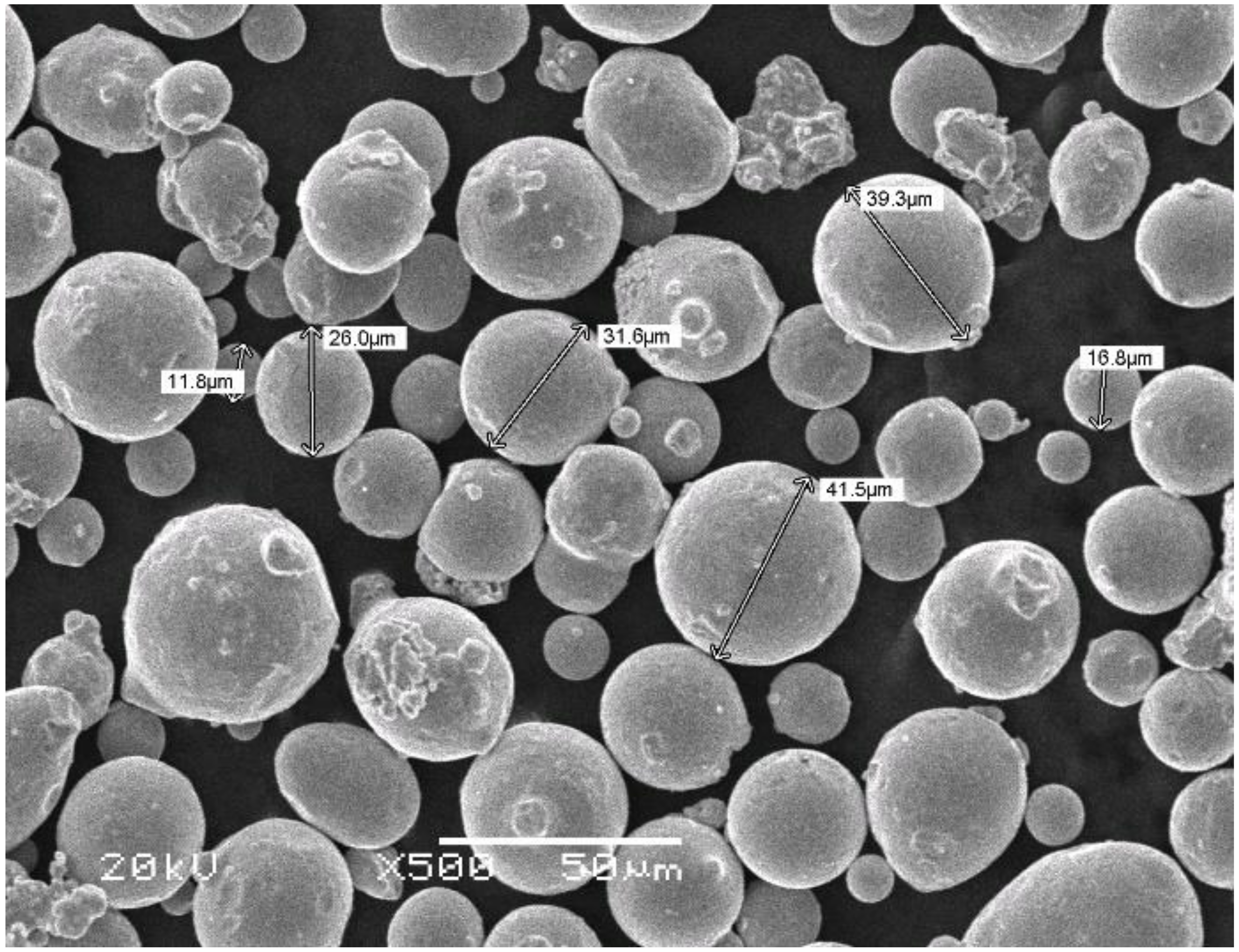
SLM technology uses spherical powder as a material, with a certain variety of types, depending on the size and the kind of material. It is therefore necessary to properly define the type of powder used in this study. DSS-SLM specimens are to be manufactured from duplex spherical purchased powder obtained by an atomization process. The size of the powder particles is in the range of 15 μm to 45 μm, below the layer height (Th) set at 50 μm. The grains of powder cannot exceed this height, as this would impair the properties of the final product. According to the manufacturer’s certificate, the mean value is 32.4 microns in diameter, and the standard deviation is 8.1 microns. In addition, an excessive powder size results in a worsening of the surface finish and a higher porosity of the finished product [34]. Figure 1 depicts the DSS-SLM powder used.

Figure 1.
SEM microstructure of DSS-SLM powder.
Another fundamental factor is the chemical composition of the steel used. The high chromium and molybdenum contents allow the use of DSSs under conditions where pitting, crevices, and stress corrosion cracking would be critical for other types of steel. A lower amount of nickel than austenitic steel reduces manufacturing costs. The ferrite grains are enriched in P, Mo, Si, and Cr, whereas austenite grains are enriched in N, Ni, Cu, and Mn [35,36]. Table 2 shows the chemical composition of both the powder and the base material. Both compositions are within the element content ranges for this type of steel, which are: C less than 0.03, Cr between 21.0 and 23.0, Ni between 4.5 and 6.5, Mo between 2.5 and 3.5, and N less than 0.22.
Table 2.
Chemical composition of DSS-SLM and DSS-BM.
3. Experimental Methodology
The SLM equipment (ALBA 300 model developed jointly by the companies Samylabs and ONA) used to manufacture the test specimens has a 300 W CW fiber laser and a wavelength of 1080 nm. It has an oxygen sensor for monitoring the inert chamber and regulating the use of argon, and it is capable of dropping below 1000 ppm of oxygen.
The quality of the final product and its mechanical properties will largely depend on the configurable parameters of the SLM equipment. These variables are also unique and independent for each material, with the optimal parameters of a steel, a titanium alloy, or a polymer being very different. Such a big difference is essentially due to the thermal properties and absorption capacity of laser radiation for a specific wavelength of the material in question [37].
Volumetric energy density (VED) represents the amount of energy transferred to the material per volumetric unit. In order to calculate it, the following Equation (1) is used [38], relating the laser power (P), the laser speed (S), the hatching of the laser beam between lines (H), and the layer thickness (Th), set at 50 μm.
The optimization of the parameters mentioned above will define the optimal manufacturing process. To this end, an experiment design based on the response surface methodology has been created. It is a group of mathematical techniques utilized for analyzing complex relationships between multiple independent parameters and the responses they produce on a dependent variable. In order to develop this technique, it is necessary to know the fixed parameters of the SLM equipment. The main fixed parameters are the height or thickness of the powder layer (Th), with a value of 50 μm, and the wavelength of the laser beam, which measures 1080 nm. With these values defined, the mechanical properties of steel depend mainly on the following parameters: laser power, laser beam separation between lines, and laser speed. A preliminary study was performed to investigate the process parameter window that enabled the fabrication of components with an energy density capable of melting the DSS-2205. With those results, the ranges of values containing the optimal were fixed. The intervals are shown in Table 3.
Table 3.
Variable parameters used in the design of experiments.
In the response surface method, these three parameters are related to each other with the expression S = ƒ (P*, S*, H*) of Equation (2). In this quadratic function, the variables P*, S*, and H* represent the coded equivalences of the real parameters P, S, and H within the interval defined for the experiment design of [−1, 1]. Parameter coding is performed using Equation (3). For a real value Xi, its encoded value will be xi when XiNsup and XiNinf are the maximum and minimum real values and is the average of real values that Xi can take [14].
Aiming to calculate the material properties from these coefficients, the Design Expert software tool v13 was used. Some characteristics can be highlighted:
- The use of the three parameters P*, S*, and H*.
- Choosing a cubic domain.
- Coding the factors with the specified interval, using Equation (3).
- In order to measure test variability, the cubic matrix has three levels for each input parameter, with two replicates at the midpoint of the domain.
- The application of Equation (2) to adapt the five response surfaces to the five material properties analyzed.
Table 4 depicts both the experimental matrix of the coded factors, as well as the real value of these same parameters, and the volumetric energy density that these combinations will consume.
Table 4.
Proposal for the design of experiments.
The experimental phase of this research was developed by testing cylindrical specimens for uniaxial tensile testing, using the standard ASTM E8-E8M [39] to choose the geometry of specimens. With the measurements defined, the test specimens that constitute the experimental matrix tests from Table 4 have been reproduced.
Once the specimens have been manufactured, they were subjected to the commonly used heat treatment of quenching at 1050 °C for one hour, before being quenched in water to produce the austenitization process. In this way, the percentage of austenite in the microstructure is increased and the expected properties for DSS-2205 are achieved.
All the tensile tests were carried out on universal testing machines from the company MTS, equipped with class A extensometers. The test speed was 0.01 mm/s. For the parameter optimization process, small cylindrical specimens with a diameter of 3.5 mm and a gauge length of 20 mm were used. For the optimization of heat treatments, cylindrical specimens with a diameter of 6 mm and a gauge length of 25 mm were used. No machining process is applied to the specimens afterward, with the roughness value Ra being around 10 microns.
4. Optimization Procedure
Once the tensile tests were completed, the collected data were processed to represent the engineering stress–strain curve for each test from the experimental matrix in Table 4. Figure 2 shows the two typical behaviors that were observed during tests and depicts the most characteristic broken specimen sections. On the one hand, some specimens have suffered brittle fractures, such as specimens 5 and 7, and on the other hand, others displayed more ductile behavior, such as specimens 2 and 13. The brittle behavior observed is characterized by low fracture strain, implying that the necking of the specimen is practically non-existent, and thus the reduction of the area is very small. In contrast, in ductile behavior, the fracture strain and reduction of area are high, and necking occurs in the fracture zone. As can be seen in the fracture surfaces of the micrographs, the ductility of the material is directly related to the reduction of the area of the specimen at failure and to the necking of the specimen. Specimen 7 shows that the laser beam has not been able to completely weld the steel, leaving more pores and reducing the relative density of the material, while specimen 2 shows a more homogeneous and compact matrix.
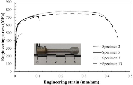
Figure 2.
Engineering stress–strain curve of the tested samples.
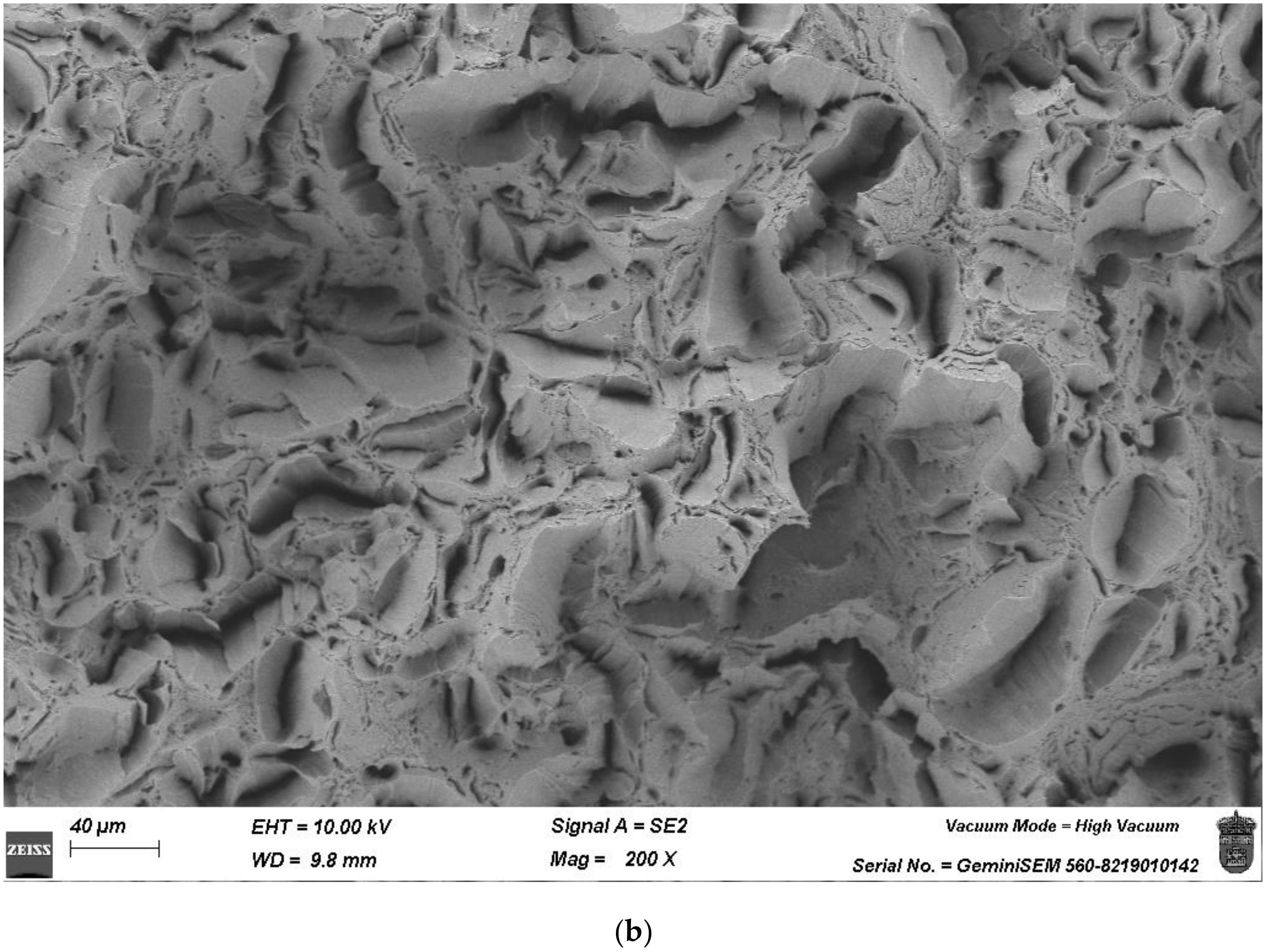
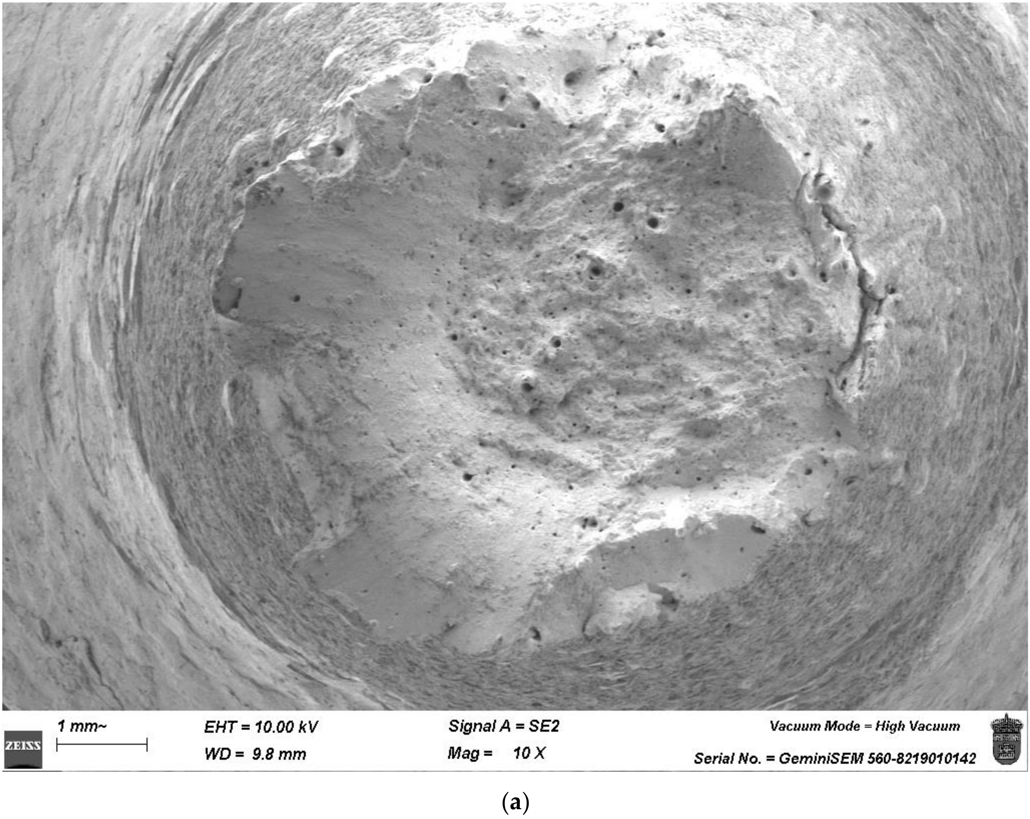
The most representative specimens for the ductile and brittle behaviors are specimens 2 and 7, whose fracture surfaces have been analyzed with the scanning electron microscope (SEM). Comparing Figure 3 and Figure 4, the differences in the ductile behavior are very remarkable. However, specimen 2 still has big pores as it does not have the optimal process parameters. In Figure 3, it can be clearly observed how the specimen has experienced necking in the fracture zone, considerably reducing its initial diameter. Conversely, in Figure 4, it is evident that the fracture occurred without necking in the fracture zone. The detail in Figure 4 clearly shows the lack of powder fusion due to the low energy per unit volume provided by the laser during the manufacturing process.
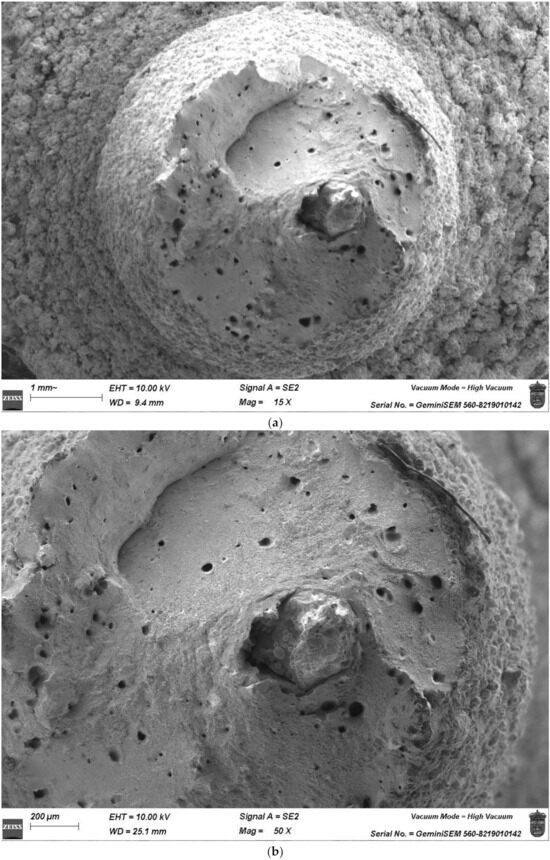
Figure 3.
The fracture surface of specimen 2: (a) magnitude 15×, (b) magnitude 50×.
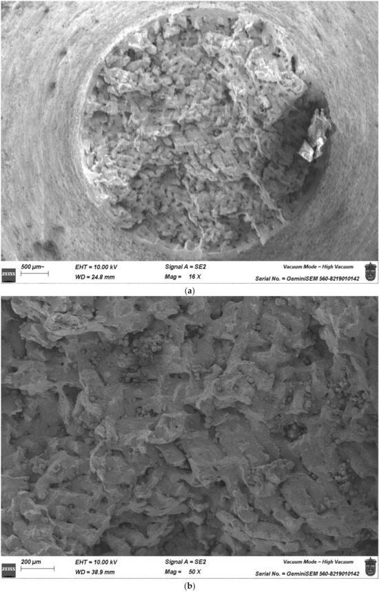
Figure 4.
The fracture surface of specimen 7: (a) magnitude 16×, (b) magnitude 50×.
For every test from Table 4, the values for all the analyzed properties (D, σ0.2, σuts, εr, and A) have been obtained, and these are depicted in Table 5. Using the calculated responses and with the aid of the Design Expert software, a mathematical model based on a quadratic function was applied to generate the response surfaces for each of them and the corresponding coefficients of determination (R2). These surfaces are characterized by Expressions (4–8).
Table 5.
Values of the mechanical properties analyzed for DSS-2205 in the design of experiments.
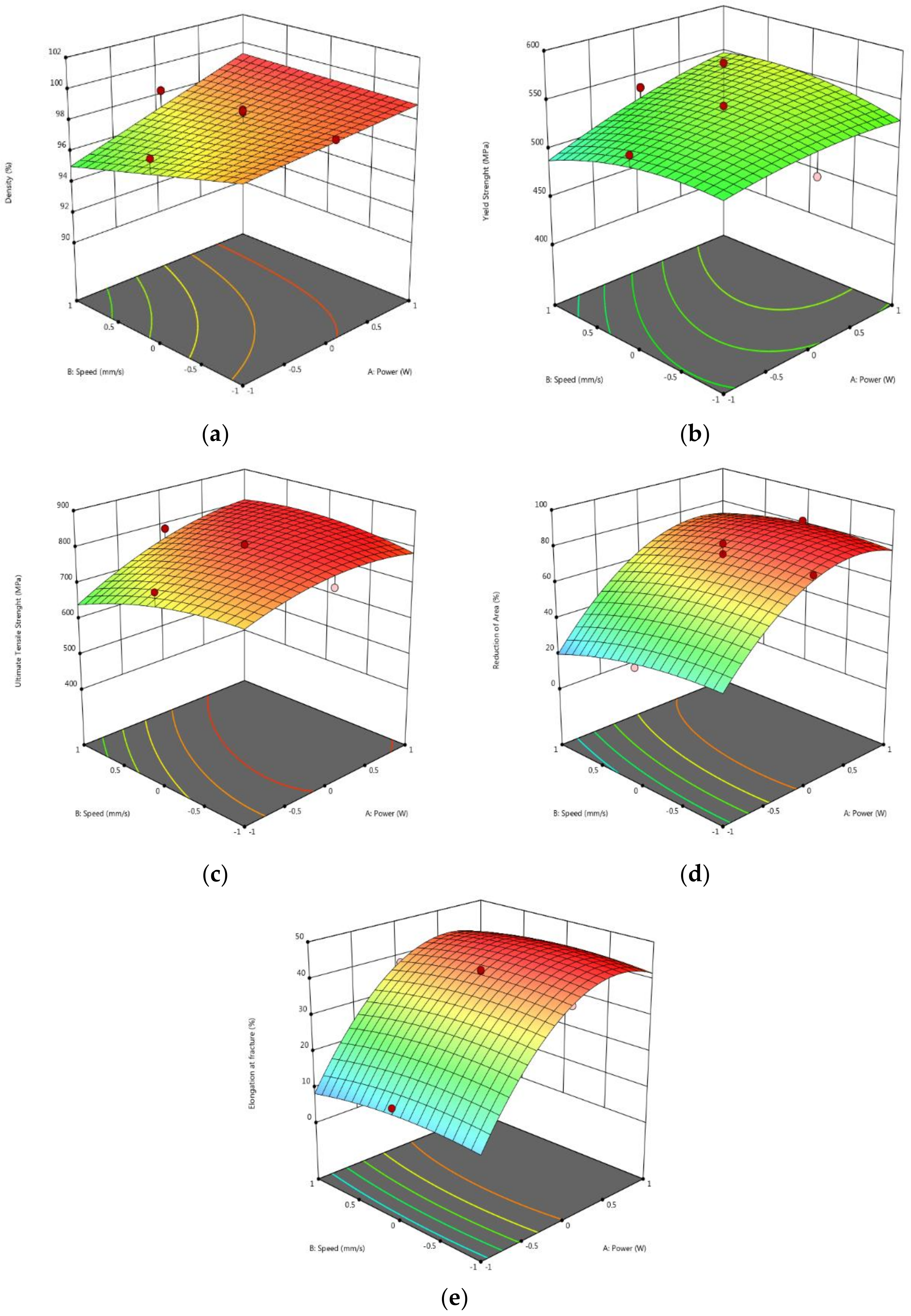
As an example, Figure 5 shows the response surfaces of the mechanical properties for the encoded H* = 0. In the graphs, the color is automatically adjusted for each result, varying from dark blue for the lowest value to red for the highest value in the studied range.

Figure 5.
Response surfaces for H* = 0. (a) Density; (b) Yield strength; (c) Ultimate tensile stress; (d) Area reduction; (e) Elongation at fracture.
As the surfaces for every response have been obtained, the optimal solution for manufacturing DSS-SLM steel can be found. The numerical optimization tool built into the program was used.
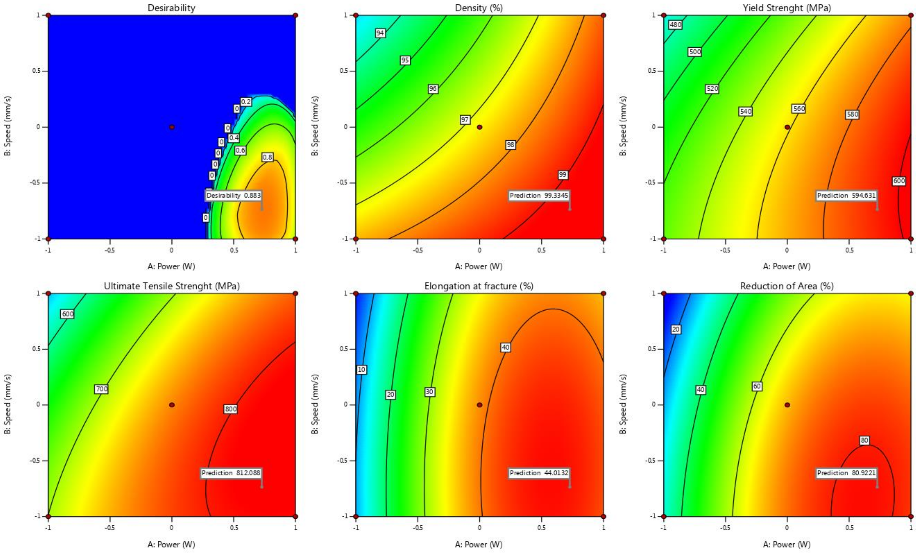
In this case, the optimization algorithm seeks to maximize the quantitative value of the mechanical properties and the density. Then, a permissible range is delimited for each of the given responses, within which the optimal result will be found. These boundary conditions will need to be defined for each response of the experiment design. At the end of the calculation, the software shows response predictions for all output variables. In addition, it generates an extra graph “desirability”, which is a response surface that depicts the maximized average value of all the properties. The higher value of this surface marks the optimal parameters. A color map is generated, ranging from dark blue, representing the area where it is not advisable to choose the parameters, to red, representing the optimal area for parameter selection.
Figure 6 presents the predictions of the responses corresponding to the solution identified as optimal. In these graphs, the laser beam separation (H*) takes the value of 1 and the other two variable parameters are represented. These surfaces are visualized on a two-dimensional plane, relating the responses to the power (P*) and velocity (S*) values of the laser.
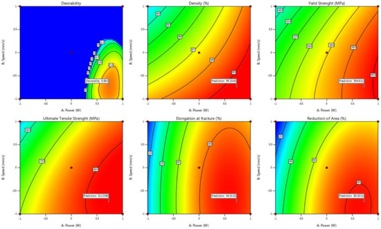
Figure 6.
Parameter optimization based on S* and P* [H* = 1].
Table 6 provides a summary of the print parameters selected in Figure 6, as well as the estimated resulting properties of the identified optimal solution. The decoded values of the parameters shown in Table 6 are P = 174.9 W, S = 639.6 mm/s, and H = 0.12 mm. For these parameters, the VED is 45.57 J/mm3.
Table 6.
Optimal solution chosen and response estimates.
5. Results and Discussion
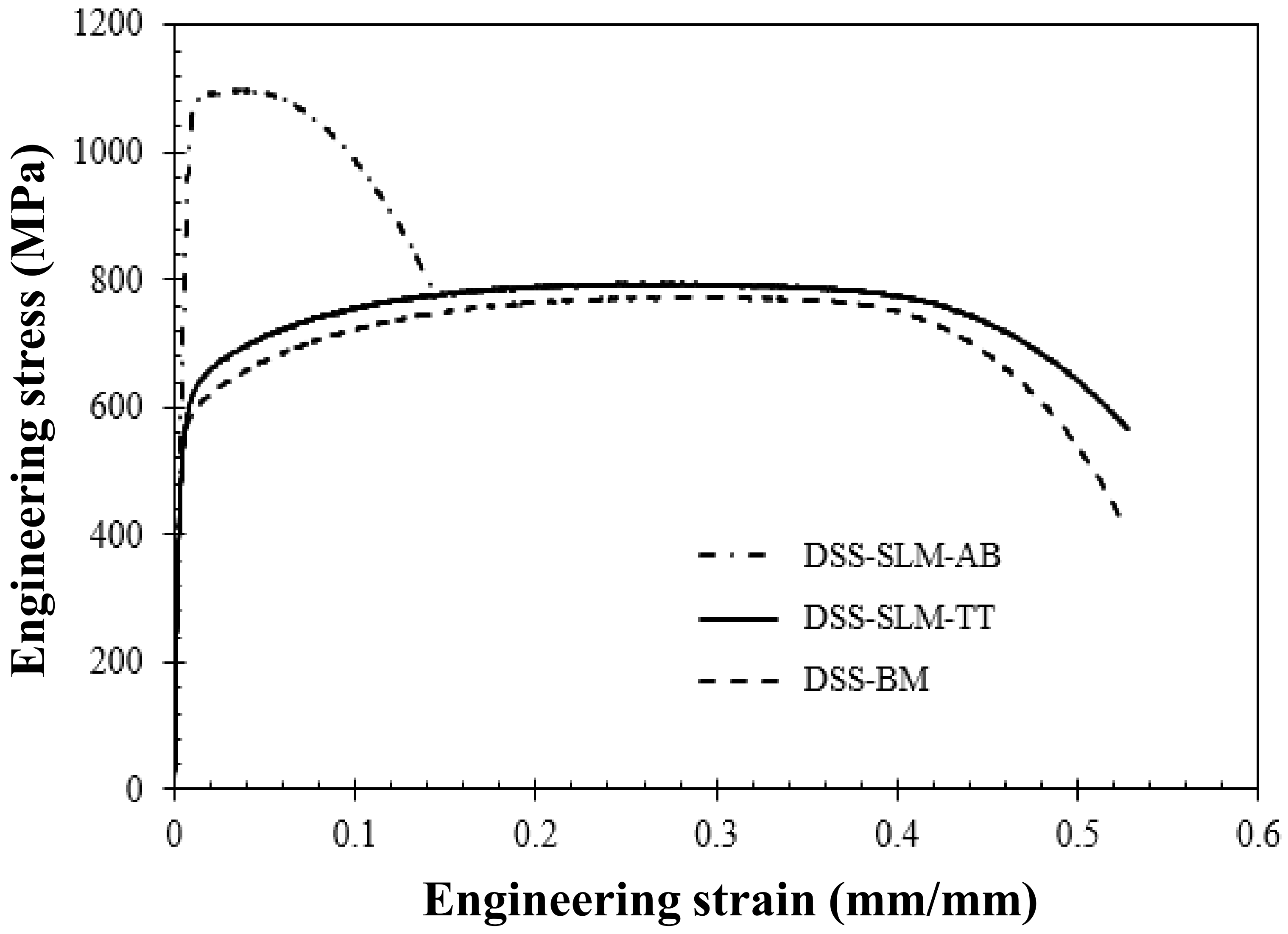
With the chosen values, it is necessary to experimentally check the optimal mechanical behavior of the specimens. To this end, SLM specimens have been manufactured using the chosen parameters. They have been heat-treated and tested. The results for the DSS-2205 obtained by additive manufacturing, both heat-treated (DSS-SLM-TT) and as-built (DSS-SLM-AB), are shown in Table 7. Despite the DSS-SLM-AB having a higher σuts and σ0.2, its εr and A are far worse than those of the DSS-SLM-TT. This is the reason for the heat treatment because these are the properties to maximize. Figure 7 compares the engineering stress–strain curve of the reference base material (DSS-MB), DSS-SLM-TT, and DSS-SLM-AB, where it is easier to observe the differences in elongation between specimens (one single specimen per condition).
Table 7.
Properties of DSS-2205 manufactured with optimal parameters.

Figure 7.
Comparison of DSS-2205 base material with treated and untreated SLM steel.
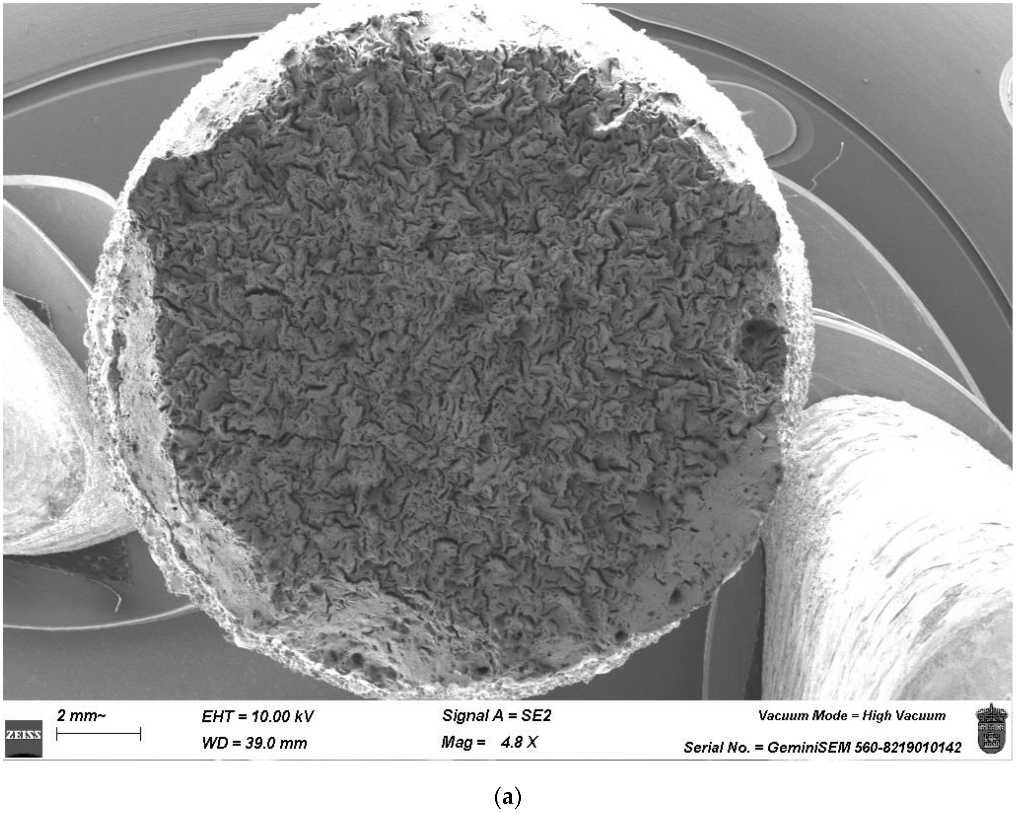
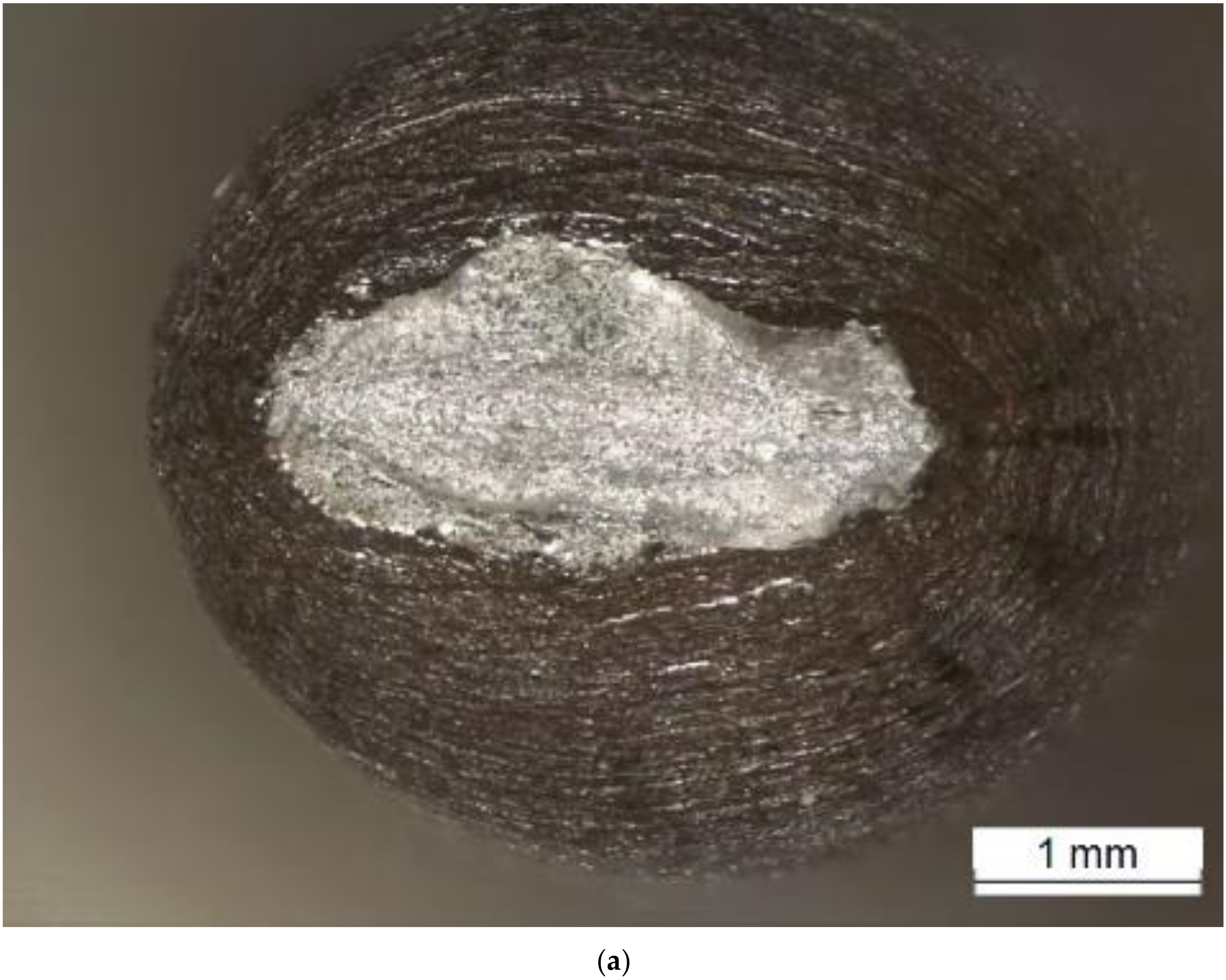
The fracture surface of the different specimens was observed with SEM. Comparing Figure 8 and Figure 9, the difference between the brittle behavior of DSS-SLM-AB and the ductile behavior of DSS-SLM-TT is clearly visible. In Figure 8, the mechanisms of brittle fracture can be clearly observed throughout the fracture section, resulting in minimal necking of the specimen. Conversely, in Figure 9, ductile fracture mechanisms in the form of microvoids can be seen, as well as necking of the specimen in the fracture zone. This same behavior is reproduced in the base material DSS-BM (Figure 10). The most remarkable difference is the shape of the necking; in DSS-SLM-TT, the neck is circular, indicating isotropic behavior, whereas in DSS-BM, the neck is elliptical, indicating anisotropic behavior due to the grain orientation caused by the hot rolling process.


Figure 8.
Fracture surface of the DSS-SLM-AB: (a) magnitude 4.8×, (b) magnitude 200×.

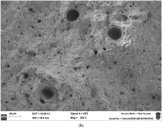
Figure 9.
Fracture surface of the DSS-SLM-TT: (a) magnitude 10×, (b) magnitude 200×.
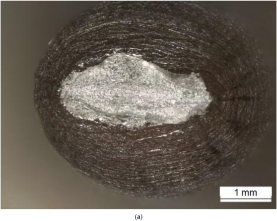
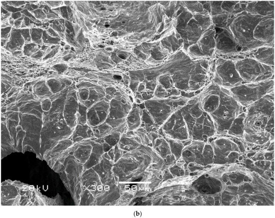
Figure 10.
Fracture surface of the DSS-BM: (a) magnitude 2×, (b) magnitude 300×.
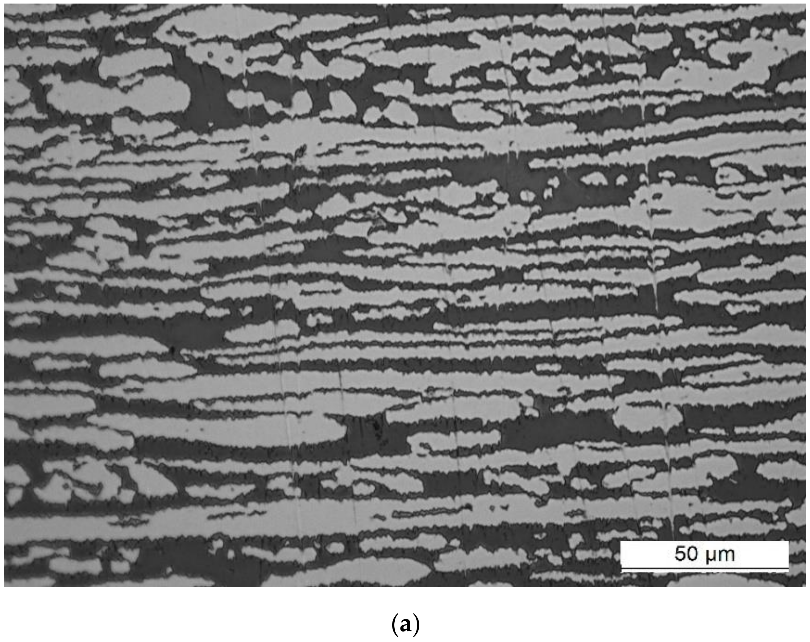
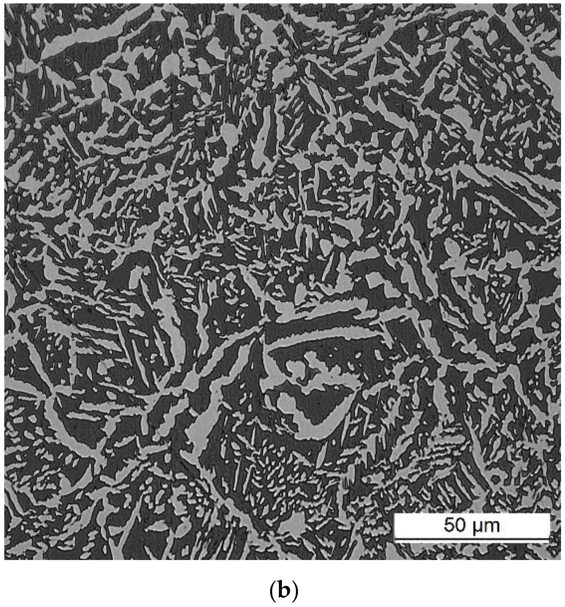
If the microstructure of the DSS-SLM-TT specimen is analyzed, the two phases of a duplex steel can be easily observed in Figure 11: the dark phase is ferrite, and the light phase is austenite. The microstructure phases have been measured by image analysis, using the software Leica—L.A.S. V4.12 for metallographic phase analysis. Figure 11 also shows the microstructure of the DSS-BM, in which a clear directionality of the austenite phase is observed, caused by the productive process of hot rolling. In the case of DSS-SLM-TT, it has been possible to achieve an austenite content of 35.91% by quenching at 1050 °C and quenching in water.


Figure 11.
Microstructure of the (a) DSS-BM and (b) DSS-SLM-TT.
Aiming to increase the content of the austenitic phase in the DSS-SLM microstructure and to maximise the εr and A, the effect of quenching temperature between the range of 975 °C to 1100 °C was analyzed based on previous research such as [17,30,33], where the typical values for DSS-2205 are within this range.
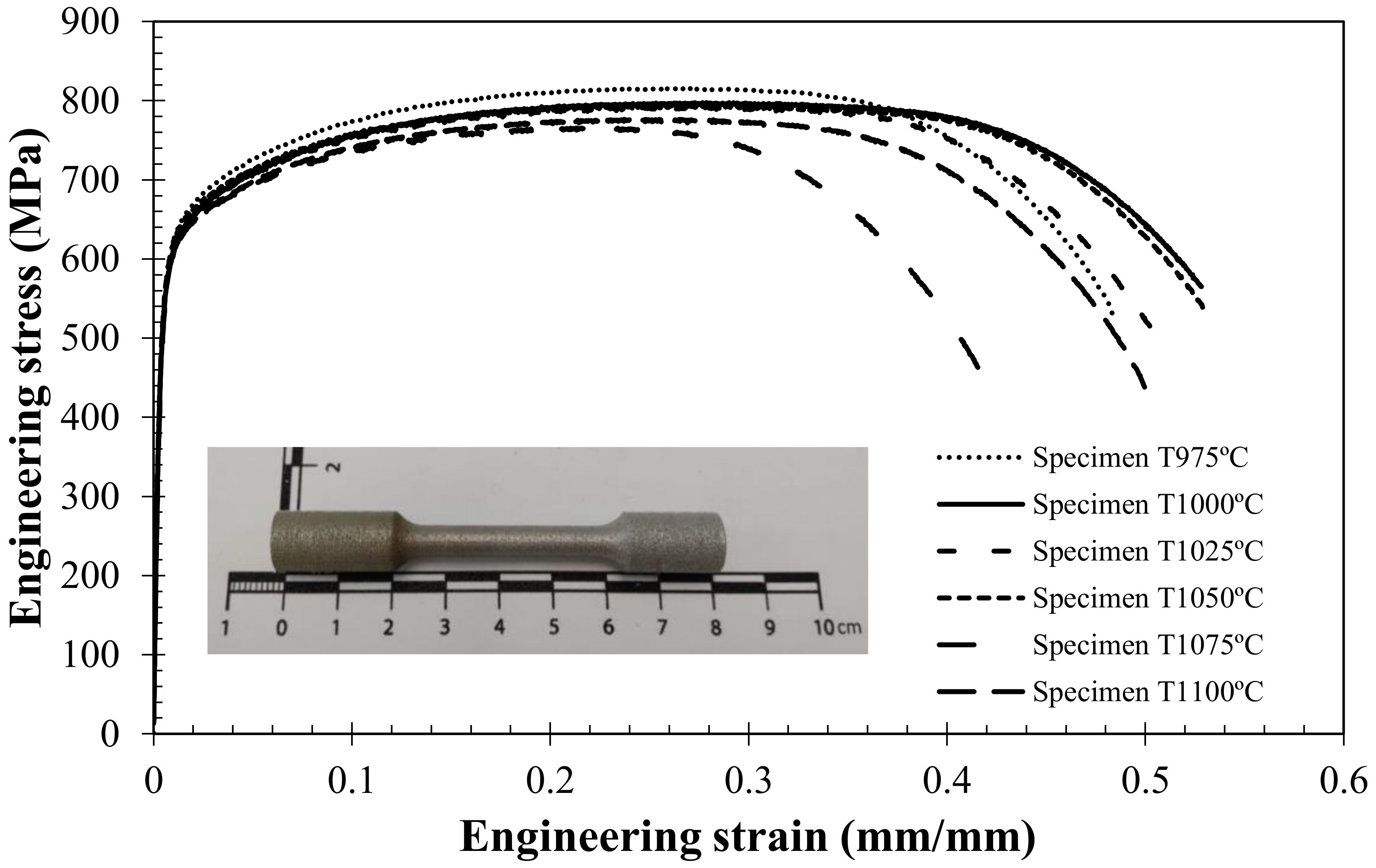
For this purpose, a new batch of specimens was manufactured by SLM using the optimal parameters obtained previously. Subsequently, uniaxial tensile tests were carried out to study the influence of the treatments on the mechanical behavior. Additionally, the phase balance of the microstructure was measured to determine which treatment results in the highest percentage of austenite. The microstructure phase balances were measured by image analysis in the same way as the previous ones were. Figure 12 shows the engineering stress–strain characteristic curves for every temperature analyzed and Table 8 shows the values obtained along with the standard deviation for three specimens for each condition. In all of them, the observed behavior is ductile and very similar, so the differences between the various heat treatments are much smaller than those observed during the optimization of the manufacturing parameters.

Figure 12.
Engineering stress–strain curve of heat-treated specimens.
Table 8.
Mechanical properties of DSS-2205-TT obtained from tensile tests.
Figure 13 depicts the microstructures of each heat treatment. With these micrographs, it has been observed that the quenching process producing the closest balance to the ideal 50/50 proportion is the one carried out at 975 °C, with 42.76% austenite. However, the results of the uniaxial tensile tests show that the increase in austenite, achieved by decreasing the temperature to 975 °C, does not correspond to an increase in the mechanical properties of DSS-2205 steel. Using the values shown in Table 8, it can be seen that specimens treated at 1000 °C have shown a higher elongation (εr) and reduction of the section at fracture (A) compared to those previously mentioned. It should be noted that, as the treatment temperature rises, the elongation (εr) and cross-section reduction (A) decrease, while the yield strength (σ0.2) and the ultimate tensile strength (σuts) remain practically constant throughout the range.
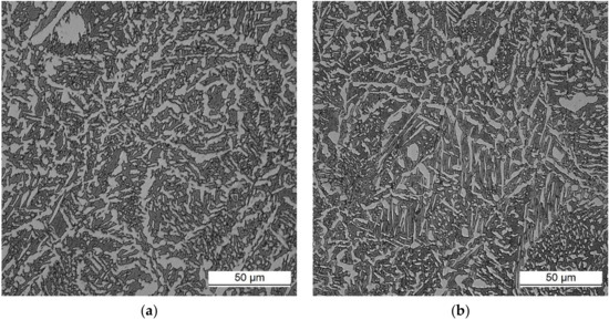
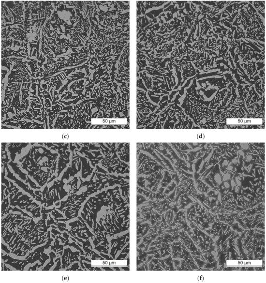
Figure 13.
Microstructure of DSS-SLM-TT at different treatment temperatures. (a) TT 975 °C; TT 1000 °C; (c) TT 1025 °C; (d) TT 1050 °C; (e) TT 1075 °C; (f) TT 1100 °C.
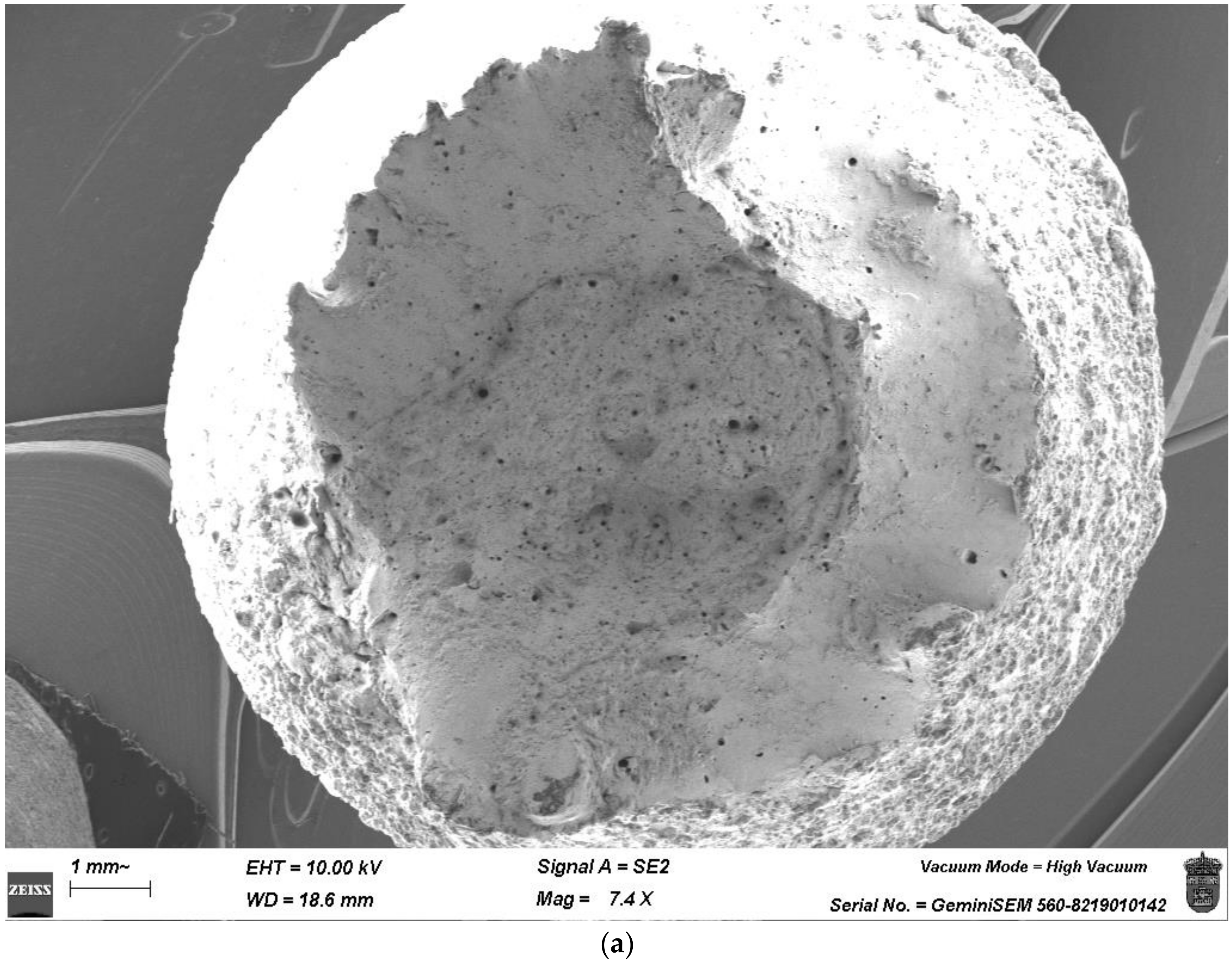
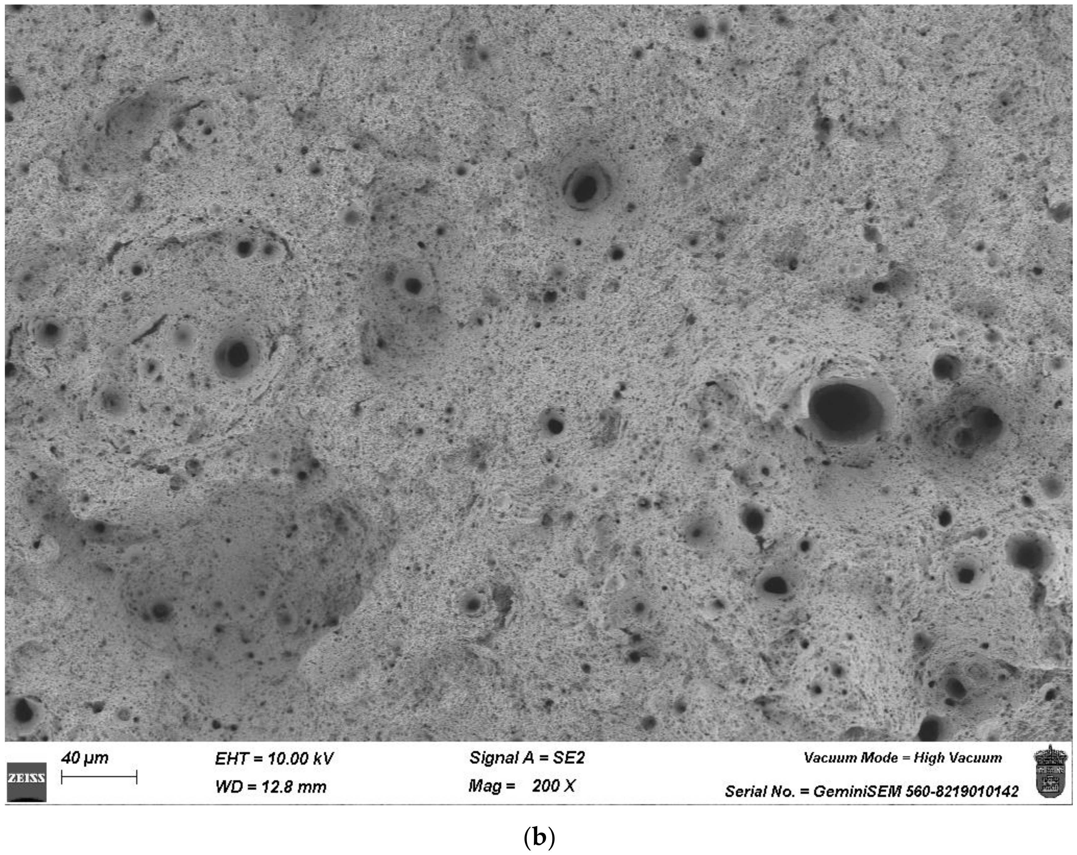
In this article, the mechanical properties prioritized are the elongation at fracture (εr) and the reduction of area (A). These properties are fundamental in safety terms because the necking of a component is a sign of its worsening before the fracture stage is reached. Therefore, it can be determined that the optimal heat treatment for DSS-SLM is quenching at 1000 °C for one hour and water quenching. This heat treatment has a remarkable elongation compared with the other treatments. The fracture surface of the optimal specimen has been analyzed with SEM. In Figure 14, the ductile failure mechanisms observed in previous figures can be seen again. In Figure 15, for the specimen shown in Figure 14, a large pore surrounded by microvoids is detailed, all of which are clear signs of the ductile behavior of the specimen. The mechanical properties studied ensure the correct behavior of the material at tensile stress.


Figure 14.
Fracture surface of the DSS-SLM at 1000 °C, with the optimal process parameters and heat treatment: (a) magnitude 7.4×, (b) magnitude 200×.
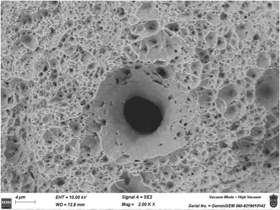
Figure 15.
Pores observed in the fracture surface of the specimen, magnitude 2000×.
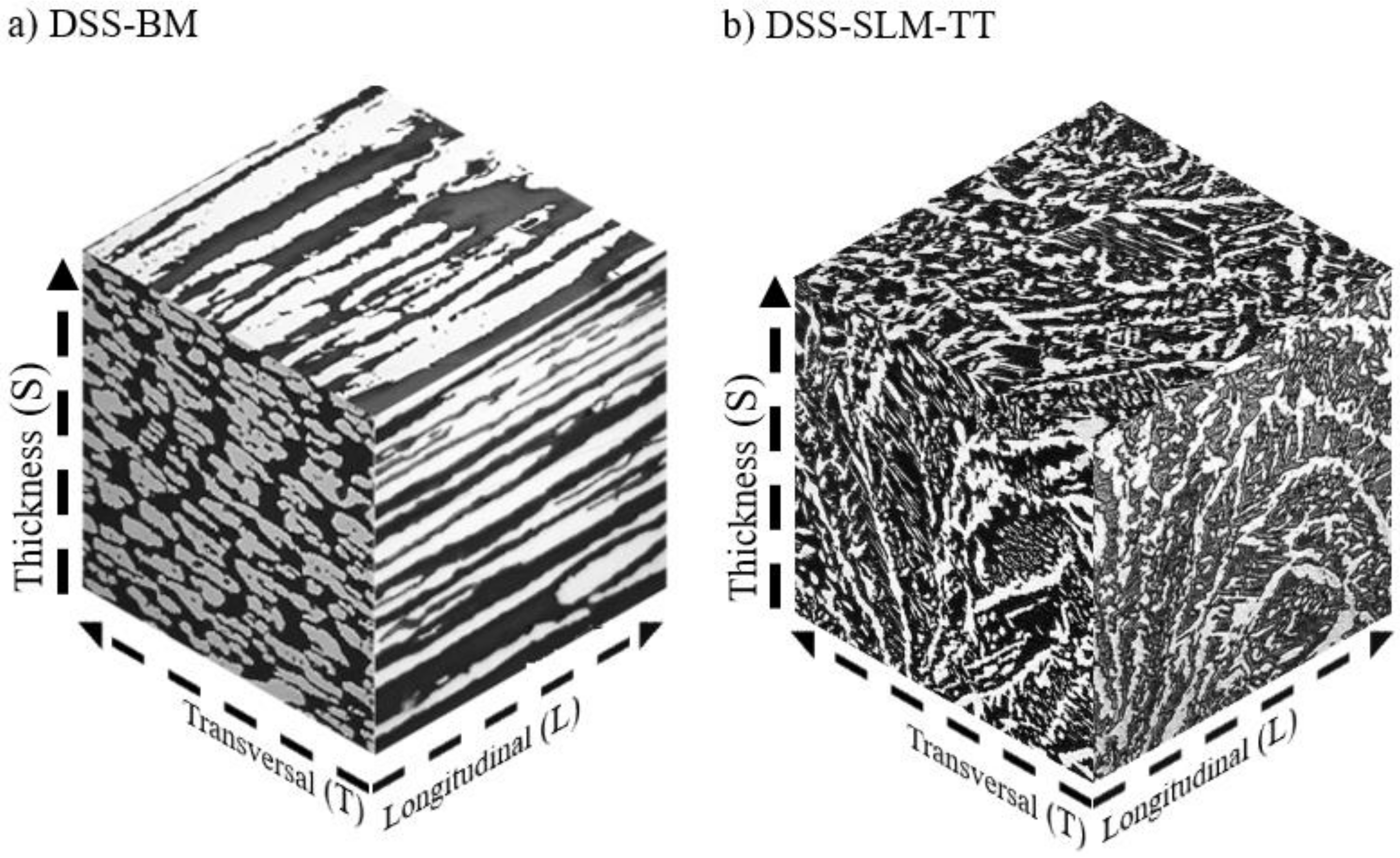
In order to study the direction of the austenite phases of the steel microstructure, a cube of micrographs was constructed in the three directions of space for both the DSS-BM and the DSS-SLM-TT. These cubes are depicted in Figure 16. In the hot-rolled condition, the elongation of the austenitic phase in the longitudinal direction is clearly appreciated. Additively manufactured steel has a dendritic microstructure in the direction of the thickness (S). This is related to directional solidification along the build direction as the preferred solidification direction is the one with the highest heat flow, i.e., along ferrite grains. Such an alignment of the building direction results in epitaxial growth across several layers, as has been studied in [32,40]. Despite the microstructure being completely different in the two cases shown in Figure 16, mechanical behavior as similar as possible to the base material has been achieved.
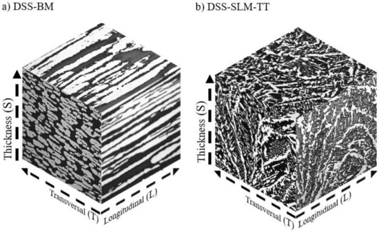
Figure 16.
Micrograph directionality cubes: (a) DSS-BM and (b) DSS-SLM-TT.
6. Conclusions
In the present work, the optimal printing parameters for the manufacture of components with DSS-2205 by SLM have been defined and an optimal austenitization treatment has been chosen. Aiming to obtain these parameters, the Design Expert software has been used for the analysis of the density and mechanical properties (σ0.2, σuts, εr, and A) of the DSS-2205 material, applying the methodology of the response surfaces. At the same time, uniaxial tensile tests have been carried out to experimentally verify the real behavior of the analyzed steel. The specimens used were produced with the SLM technique and then treated by quenching at 1050 °C and quenching in water. The properties of additively manufactured DSS-2205 have been compared with a base material produced by traditional methods, which has served as a reference. In this way, it has been shown that it is possible to reproduce its behavior, with the dispersion of the resulting properties being less than 4% and a relative density of 99.82%, which is very close to the desired density. The optimal printing parameters P = 174.9 W, S = 639.6 mm/s, and H = 0.12 mm are thus defined, with a manufacturing energy density of 45.57 J/mm3. With the manufacturing factors bounded, the variation of the mechanical properties of DSS-2205 was experimentally analyzed, depending on the heat treatment applied. The achieved austenite content with each of the treatments has been fundamental in this analysis. Finally, quenching at 1000 °C with water quenching is marked as optimal, providing an austenite percentage of 38.53% and the mechanical properties shown in Table 8. The procedures, methodology, and experimental tests used in this article are replicable and can be repeated in the optimization of other materials in a similar way.
Author Contributions
Conceptualization, I.I.C.; Investigation, N.M., L.M., R.R.-A., A.D., J.M.A. and I.I.C.; Writing—original draft, N.M.; Writing—review & editing, A.D., J.M.A. and I.I.C.; Supervision, J.M.A. and I.I.C.; Funding acquisition, J.M.A. and I.I.C. All authors have read and agreed to the published version of the manuscript.
Funding
The authors would like to thank the Spanish Government for the financial support received to perform the research project PID2021-124768OB-C21 and TED2021-130413B-I00. This work was also supported by the Regional Government of Castilla y León (Junta de Castilla y León) and by the Ministry of Science and Innovation MICINN and the European Union NextGenerationEU/PRTR through the project MA2TEC (C17.I01).
Data Availability Statement
The data presented in this study are available on request from the corresponding author (privacy).
Conflicts of Interest
The authors declare no conflict of interest.
References
- Pereira, T.; Kennedy, J.V.; Potgieter, J. A comparison of traditional manufacturing vs additive manufacturing, the best method for the job. Procedia Manuf. 2019, 30, 11–18. [Google Scholar] [CrossRef]
- Bogers, M.; Hadar, R.; Bilberg, A. Additive manufacturing for consumer-centric business models: Implications for supply chains in consumer goods manufacturing. Technol. Forecast. Soc. Chang. 2016, 102, 225–239. [Google Scholar] [CrossRef]
- Fernández-Miguel, A.; García-Muiña, F.E.; Jiménez-Calzado, M.; Román, P.M.S.; del Hoyo, A.P.F.; Settembre-Blundo, D. Boosting business agility with additive digital molding: An Industry 5.0 approach to sustainable supply chains. Comput. Ind. Eng. 2024, 192, 110222. [Google Scholar] [CrossRef]
- Kanyilmaz, A.; Demir, A.G.; Chierici, M.; Berto, F.; Gardner, L.; Kandukuri, S.Y.; Kassabian, P.; Kinoshita, T.; Laurenti, A.; Paoletti, I.; et al. Role of metal 3D printing to increase quality and resource-efficiency in the construction sector. Addit. Manuf. 2022, 50, 102541. [Google Scholar] [CrossRef]
- Song, B.; Wen, S.; Yan, C.; Wei, Q.; Shi, Y. Selective Laser Melting for Metal and Metal Matrix Composites, 1st ed.; Huazhong University: Wuhan, China; Academic Press: Cambridge, MA, USA, 2020. [Google Scholar]
- Gibson, I.; Rosen, D.; Stucker, B. Additive Manufacturing Technologies 3D Printing, Rapid Prototyping, and Direct Digital Manufacturing, 2nd ed.; Springer Science + Business Media: New York, NY, USA; Berlin/Heidelberg, Germany; Dordrecht, The Netherlands; London, UK, 2009. [Google Scholar] [CrossRef]
- Bakhtiarian, M.; Omidvar, H.; Mashhuriazar, A.; Sajuri, Z.; Gur, C.H. The effects of SLM process parameters on the relative density and hardness of austenitic stainless steel 316L. J. Mater. Res. Technol. 2024, 29, 1616–1629. [Google Scholar] [CrossRef]
- Ren, X.; Liu, H.; Lu, F.; Huang, L.; Yi, X. Effects of processing parameters on the densification, microstructure and mechanical properties of pure tungsten fabricated by optimized selective laser melting: From single and multiple scan tracks to bulk parts. Int. J Refract. Met. Hard. Mater. 2021, 96, 105490. [Google Scholar] [CrossRef]
- Mao, S.; Zhang, D.Z.; Ren, Z.; Fu, G.; Ma, X. Effects of process parameters on interfacial characterization and mechanical properties of 316L/CuCrZr functionally graded material by selective laser melting. J. Alloys Compd. 2022, 899, 163256. [Google Scholar] [CrossRef]
- Bayat, M.; Thanki, A.; Mohanty, S.; Witvrouw, A.; Yang, S.; Thorborg, J.; Tiedje, N.S.; Hattel, J.H. Keyhole-induced porosities in Laser-based Powder Bed Fusion (L-PBF) of Ti6Al4V: High-fidelity modelling and experimental validation. Addit. Manuf. 2019, 30, 100835. [Google Scholar] [CrossRef]
- King, W.E.; Barth, H.D.; Castillo, V.M.; Gallegos, G.F.; Gibbs, J.W.; Hahn, D.E.; Kamath, C.; Rubenchik, A.M. Observation of keyhole-mode laser melting in laser powder-bed fusion additive manufacturing. J. Mater. Process. Technol. 2014, 214, 2915–2925. [Google Scholar] [CrossRef]
- Zhao, W.; Xiang, H.; Yu, R.; Mou, G. Effects of laser scanning speed on the microstructure and mechanical properties of 2205 duplex stainless steel fabricated by selective laser melting. J. Manuf. Process. 2023, 94, 1–9. [Google Scholar] [CrossRef]
- Dehghani, K.; Nekahi, A.; Mirzaie, M.A.M. Using response surface methodology to optimize the strain aging response of AA5052. Mater. Sci. Eng. A 2010, 527, 7442–7451. [Google Scholar] [CrossRef]
- Cuesta, I.I.; Díaz, A.; Rojo, M.A.; Peral, L.B.; Martínez, J.; Alegre, J.M. Parameter Optimisation in Selective Laser Melting on C300 Steel. Appl. Sci. 2022, 12, 9786. [Google Scholar] [CrossRef]
- Lu, H.; Dong, Q.; Yan, S.; Chen, X.; Wang, X. Development of flexible grouting material for cement-stabilized macadam base using response surface and genetic algorithm optimization methodologies. Constr. Build. Mater. 2023, 409, 133823. [Google Scholar] [CrossRef]
- Sheng, J.; Du, M.; Li, Y.; Ma, G.; Chen, W.; Zheng, Y.; Zhan, F.; Ren, J.; Gi, R.; La, P. Deformation Mechanism of Bimodal Structured 2205 Duplex Stainless Steel in Two Yield Stages. J. Wuhan Univ. Technol. Mater. Sci. Ed. 2023, 38, 184–191. [Google Scholar] [CrossRef]
- Papula, S.; Song, M.; Pateras, A.; Chen, X.-B.; Brandt, M.; Easton, M.; Yagodzinskyy, Y.; Virkkunen, I.; Hänninen, H. Selective laser melting of duplex stainless Steel 2205: Effect of post-processing heat treatment on microstructure, mechanical properties, and corrosion resistance. Materials 2019, 12, 2468. [Google Scholar] [CrossRef] [PubMed]
- Xiao, Y.; Tang, J.; Wang, Y.; Lin, B.; Nie, Z.; Li, Y.; Normand, B.; Wang, H. Corrosion behavior of 2205 duplex stainless steel in NaCl solutions containing sulfide ions. Corros. Sci. 2022, 200, 110240. [Google Scholar] [CrossRef]
- Ye, Z.; Guan, L.; Li, Y.; Zhong, J.; Liao, L.; Xia, D.; Huang, J. Understanding the galvanic corrosion of Cu-Ni alloy/2205 DSS couple using electrochemical noise and microelectrochemical studies. Corros. Sci. 2023, 224, 111512. [Google Scholar] [CrossRef]
- Kan, B.; Wu, W.; Yang, Z.; Zhang, X.; Li, J. Effects of hydrostatic pressure and pH on the corrosion behavior of 2205 duplex stainless steel. J. Electroanal. Chem. 2021, 886, 115134. [Google Scholar] [CrossRef]
- Liu, H.; Zhang, W.; Zhao, Z.; Lai, H.; Liu, H. Broken passive film and subsequent pitting corrosion behavior of 2205 duplex stainless steel induced by marine fungus Aspergillus terreus in artificial seawater. Corros. Sci. 2023, 218, 111147. [Google Scholar] [CrossRef]
- Xu, D.; Xia, J.; Zhou, E.; Zhang, D.; Li, H.; Yang, C.; Li, Q.; Lin, H.; Li, X.; Yang, K. Accelerated corrosion of 2205 duplex stainless steel caused by marine aerobic Pseudomonas aeruginosa biofilm. Bioelectrochemistry 2017, 113, 1–8. [Google Scholar] [CrossRef] [PubMed]
- Xie, X.F.; Dong, Z.; Li, S.; Wan, Y. Experimental investigation and micromechanical modeling of load partitioning behavior of duplex stainless steel 2205 during cyclic hardening. Mater. Today Commun. 2023, 35, 106202. [Google Scholar] [CrossRef]
- Wang, W.; Wang, J.; Wang, Q.; Huang, X.; Lu, G.; Liu, Y.; Liu, C. Ferrite-austenite synergistic deformation behavior in a 2205 duplex stainless steel containing equiaxed austenite domains. Mater. Charact. 2023, 205, 113363. [Google Scholar] [CrossRef]
- Gunn, R. (Ed.) Duplex Stainless Steels: Microstructure, Properties and Applications, 1st ed.; Woodhead Publishing: Glasgow, UK; Beaune, France, 1997; Volume 1. [Google Scholar]
- de Farias Azevedo, C.R.; Pereira, H.B.; Wolynec, S.; Padilha, A.F. An overview of the recurrent failures of duplex stainless steels. Eng. Fail. Anal. 2019, 97, 161–188. [Google Scholar] [CrossRef]
- Zhang, Q.; Jiao, X.; Yu, J.; Xiong, X. Investigation of Selective Laser Melting of 2205 steel precipitates and heat treatment improvement. J. Mater. Res. Technol. 2024, 29, 2306–2315. [Google Scholar] [CrossRef]
- Saeidi, K.; Kevetkova, L.; Lofaj, F.; Shen, Z. Novel ferritic stainless steel formed by laser melting from duplex stainless steel powder with advanced mechanical properties and high ductility. Mater. Sci. Eng. A 2016, 665, 59–65. [Google Scholar] [CrossRef]
- Freitas, B.J.M.; Rodrigues, L.C.M.; Claros, C.A.E.; Botta, W.J.; Koga, G.Y.; Bolfarini, C. Ferritic-induced high-alloyed stainless steel produced by laser powder bed fusion (L-PBF) of 2205 duplex stainless steel: Role of microstructure, corrosion, and wear resistance. J. Alloys Compd. 2022, 918, 165576. [Google Scholar] [CrossRef]
- Hengsbach, F.; Koppa, P.; Duschik, K.; Holzweissig, M.J.; Burns, M.; Nellesen, J.; Tillmann, W.; Tröster, T.; Hoyer, K.-P.; Schaper, M. Duplex stainless steel fabricated by selective laser melting-Microstructural and mechanical properties. Mater. Des. 2017, 133, 136–142. [Google Scholar] [CrossRef]
- Fang, Y.; Kim, M.K.; Zhang, Y.; Kim, T.; No, J.; Suhr, J. A new grain refinement route for duplex stainless steels: Micro-duplex stainless steel matrix composites processed by laser powder bed fusion. Mater. Sci. Eng. A 2023, 881, 145351. [Google Scholar] [CrossRef]
- Haghdadi, N.; Ledermueller, C.; Chen, H.; Chen, Z.; Liu, Q.; Li, X.; Rohrer, G.; Liao, X.; Ringer, S.; Primig, S. Evolution of microstructure and mechanical properties in 2205 duplex stainless steels during additive manufacturing and heat treatment. Mater. Sci. Eng. A 2022, 835, 142695. [Google Scholar] [CrossRef]
- Nigon, G.N.; Isgor, O.B.; Pasebani, S. The effect of annealing on the selective laser melting of 2205 duplex stainless steel: Microstructure, grain orientation, and manufacturing challenges. Opt. Laser Technol. 2021, 134, 106643. [Google Scholar] [CrossRef]
- Habibnejad-Korayem, M.; Lalh, M.; Schunk, C.; Zou, Y. Offsize particle size utilization for laser powder bed fusion processing of plasma atomized Ti-6Al-4V powders: Impacts on part properties and powder safety. J. Manuf. Process. 2023, 107, 559–573. [Google Scholar] [CrossRef]
- Pan, M.; Zhang, X.; Chen, P.; Su, X.B.; Misra, R.D.K. The effect of chemical composition and annealing condition on the microstructure and tensile properties of a resource-saving duplex stainless steel. Mater. Sci. Eng. A 2020, 788, 139540. [Google Scholar] [CrossRef]
- Iacoviello, F.; Di Cocco, V.; Franzese, E.; Natali, S. High temperature embrittled duplex stainless steels: Influence of the chemical composition on the fatigue crack propagation. Procedia Struct. Integr. 2017, 3, 308–315. [Google Scholar] [CrossRef]
- Zhou, Y.H.; Zhang, Z.H.; Wang, Y.P.; Liu, G.; Zhou, S.Y.; Li, Y.L.; Shen, J.; Yan, M. Selective laser melting of typical metallic materials: An effective process prediction model developed by energy absorption and consumption analysis. Addit. Manuf. 2019, 25, 204–217. [Google Scholar] [CrossRef]
- Thijs, L.; Verhaeghe, F.; Craeghs, T.; Van Humbeeck, J.; Kruth, J.-P. A study of the microstructural evolution during selective laser melting of Ti–6Al–4V. Acta Mater. 2010, 58, 3303–3312. [Google Scholar] [CrossRef]
- ASTM E8/E8M-16a; Standard Test Methods for Tension Testing of Metallic Materials. ASTM International: West Conshohocken, PA, USA, 2016. [CrossRef]
- Zhou, Y.; Kong, D.; Li, R.; He, X.; Dong, C. Corrosion of Duplex Stainless Steel Manufactured by Laser Powder Bed Fusion: A Critical Review. Acta Metall. Sin. Engl. Lett. 2024, 37, 587–606. [Google Scholar] [CrossRef]


Disclaimer/Publisher’s Note: The statements, opinions and data contained in all publications are solely those of the individual author(s) and contributor(s) and not of MDPI and/or the editor(s). MDPI and/or the editor(s) disclaim responsibility for any injury to people or property resulting from any ideas, methods, instructions or products referred to in the content. |
© 2024 by the authors. Licensee MDPI, Basel, Switzerland. This article is an open access article distributed under the terms and conditions of the Creative Commons Attribution (CC BY) license (https://creativecommons.org/licenses/by/4.0/).