Article

Simulation Study on Ground Vibration Reduction Measures of the Elevated Subway Line

1
China Harbour Engineering Company Limited, Beijing 100027, China
2
School of Mechanical, Electronic and Control Engineering, Beijing Jiaotong University, Beijing 100044, China
*
Author to whom correspondence should be addressed.
Appl. Sci. 2024, 14(15), 6706; https://doi.org/10.3390/app14156706
Submission received: 19 June 2024 / Revised: 24 July 2024 / Accepted: 26 July 2024 / Published: 1 August 2024

Abstract

:
With the development of urban rail transportation, the environmental vibration problem caused by the running of metro vehicles has received attention. In order to reduce ground vibration near buildings caused by metro vehicles running on viaducts, this paper establishes the train–track–viaduct rigid–flexible coupling dynamics model and pier–soil–building finite element model and carries out the simulation calculation and analysis of ground vibration. The influence of train speed and fastener stiffness on ground vibration is explored, and the vibration reduction effect of the track vibration reduction pad and continuous support vibration reduction structure is studied. The results show that the ground vibration near the building caused by the train running on the viaduct decreases with the reduction in speed, when the speed is reduced to 40 km/h, the vibration attenuation is slower as the speed continues to be reduced; the reduction in the vertical stiffness of fasteners can reduce ground vibration; the arrangement of the vibration damping pad can effectively reduce ground vibration, and after installing a vibration damping pad, 0–23 Hz and 50–80 Hz ground vibration speeds are effectively suppressed. In order to meet the environmental requirements for ground vibration, the vehicle speed can be reduced to less than 35 km/h or vibration damping mats can be installed.

1. Introduction

Urban rail transit has become an irreplaceable mode of transportation for urban residents, which brings us fast and convenient travel at the same time but also brings some new problems. In recent years, the impact of environmental vibration along the urban rail transit line has attracted more and more attention [1,2]. The vibration response caused by urban rail transit spreads outward to produce secondary vibration and noise on the surrounding buildings, and people’s life and work are affected to different degrees [3,4,5]. Therefore, it is necessary to study the environmental vibration caused by urban rail transportation.
For the ground vibration problem caused by urban rail train operation, there have been many related studies, and the assessment of the ground vibration problem mainly includes empirical modeling [6], experimental analysis [7,8], and simulation prediction [9,10]. Many scholars have conducted relevant studies. Kedia et al. [11] developed empirical equations for ground vibration prediction and verified them with field measurements at Delhi Metro station sites with a maximum error of 2.66 percent and a minimum error of 0.84 percent in the prediction. Li hui Xu et al. [12] developed an analytical model to analyze the amplification of ground vibration under different buried loads in underground tunnels. Li et al. [13] analytically investigated the vertical vibration of the tunnel wall and the ground above the tunnel under different soft and rocky geological conditions at 0, 15 m, and 30 m horizontal distances from the tunnel center line based on measured data. With the improvement in computing power, numerical simulation has become an effective method to predict train-induced ground vibration. Ma et al. [14] established a sliced finite element–finite element coupled model to analyze the environmental vibration of underground tunnel trains and compared the measured results. The transmission characteristics of the environmental vibration of metro trains and the effects of rail mat stiffness and train speed on the environmental vibration of metro trains were investigated. Deng et al. [15], based on the probability density evolution method and random field theory, established a coupled model of metro train–track–shield tunnel–foundation soil and analyzed the relationship between surface vibration displacement and train speed. Ma et al. [16] proposed a new periodic tunnel–soil model with a track slab to simulate the propagation of train-induced vibrations.
Based on the simulation prediction results, reasonable damping measures are proposed to reduce environmental vibration, which is more conducive to saving resources and maintenance costs [17,18]. Depending on the propagation path of the vibration, appropriate damping measures can be taken at the vibration source, propagation path, and vibration receiver [19,20,21]. In the process of line design, the vibration analysis of train operation can timely find out the impact of vibration induced by train operation on the environment, and take corresponding countermeasures in time to reduce the high cost and adverse impact of remedial measures after line operation [22]. Ground vibration control can be achieved by installing damping fasteners and adjusting the spacing of the sleepers [23]. The installation of vibration damping pads and steel spring floating plates has been shown to be more effective for ground vibration control [24,25,26]. Guo et al. [27] numerically analyzed the floor vibration of a metro vehicle section and discussed the effect of train speed fastener configuration on the response of the floor vibration of the section. Zhao et al. [28] developed a new type of floating plate track vibration isolator by combining particle damping reduction and bandgap vibration isolation. In the frequency band of 50~150 Hz, the new floating plate track vibration isolator has a better vibration damping effect. Li et al. [29] proposed a new periodic composite rubberized concrete barrier (PCRCB) with precast assembly characteristics. The numerical study results show that the PCRCB has a better vibration damping effect on the ground under the subway train load. Wang et al. [30] designed rubber supports to reduce the effect of vertical vibration on buildings from subway operation. The implementation of vibration isolators can reduce the high-frequency response by making the natural frequency of vibration modes with large effective mass significantly lower than the dominant frequency of train-induced ground vibration. Wang et al. [31], in order to discuss the vibration control effect of vibration isolation support, established a finite element model of the track–foundation–vehicle segment structure, and the calculation results were verified with measured data. A good vibration isolation effect was achieved near the main frequency of the floor.
Along with the construction of urban rail transit, viaducts have become an important type of urban rail transit structure. Most of the above studies are about the ground vibration induced by the subway when running on underground lines and the vibration of adjacent buildings. For the viaduct line waiting to be built, the research of ground vibration damping measures is carried out by means of simulation. According to the simulation results, the speed is reasonably controlled, and an effective vibration damping scheme is adopted, in which the damping effect of installing continuous support on ground vibration is proposed in the vibration damping measures. The results of the study can not only provide a reasonable reference scheme for the line to be built to meet the environmental vibration requirements, but they are also conducive to the control of line costs. It has important engineering significance for the elevated line to be built.
This paper analyzes the ground vibration near buildings induced by metro vehicles running on viaduct lines; investigates the vibration reduction measures of controlling the speed, adjusting the stiffness of fasteners, arranging the track damping pads, and installing the track continuous support; and analyzes the vibration reduction effect of different vibration reduction measures. Therefore, this paper establishes the train–track–viaduct rigid–flexible coupling dynamics model and the piers–ground–buildings finite element model in Section 2. In Section 3, the ground vibration near the building is simulated and analyzed, and the effects of train running speed and fastener stiffness on the ground vibration are investigated. The vibration reduction effects of the track damping pads and continuous support damping structure vibration reduction measures are analyzed.

2. Numerical Model

The analysis of environmental vibration caused by elevated rail transit involves a complex system consisting of vehicles, tracks, bridges, piers, and foundation sites and buildings. The research method used in this paper is to divide the whole system into two substructures. They are the vibration source model and transmission path model. First of all, the train–track–viaduct rigid–flexible coupling dynamics model is established as the vibration source model, and the track–U-type bridge–piers are all considered as flexible body structures. The support reaction force of the pier is solved in the vibration source model, and it is used as the load input in the next step. Next, the pier–soil–building finite element model is established as the transmission path model. The solved pier support reaction force is applied to the corresponding position of the pier, and the vibration response of the pier–soil–building finite element model is calculated.

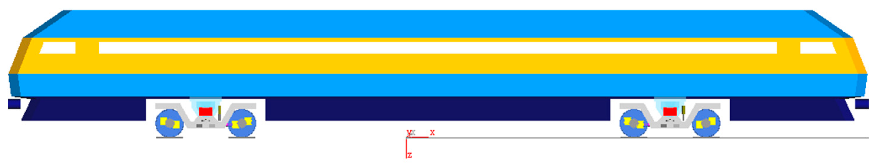
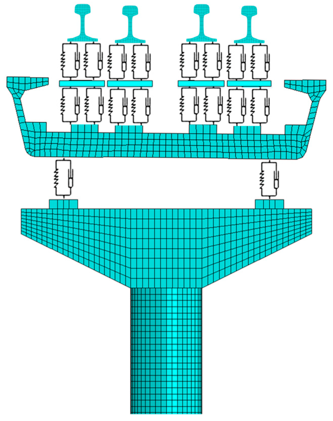
2.1. Vibration Source Model

In this paper, the SIMPACK (v.9.10) and ABAQUES (v.18.0) software programs are used to establish the train–track–viaduct rigid–flexible coupling dynamics model, as shown in Figure 1.
A train is established by the SIMPACK multi-body dynamics software and the vehicle visualization model is shown in Figure 2 below. The whole vehicle system consists of seven components, which include a body, two bogies, and four wheelsets. The body is connected to the bogies through a secondary suspension and the bogies are connected to the wheelsets through a primary suspension. The parameters of each part of the system are shown in Table 1.
Among them, wheelsets, rails, U-beams, piers, and other components are modeled as flexible bodies, and the property parameters of each component are shown in Table 2. The finite element model of each component is shown in Figure 3. According to the mass matrix M, stiffness matrix K, and the corresponding shape function U of the finite element model of the flexible structure, the modal mass matrix M and modal stiffness matrix K of the structure and the generalized vector p of the interaction between the wheel and the structure can be obtained, and the formulas are expressed as follows:
M ¯ = U T M U K ¯ = U T K U p = U T p U = ( u 1 u 2 u 3 u n )
where ul = (l = 1, 2, …, n) is the lth order modal shape of the structure, where n is the modal degree of freedom; p is the force between the wheel and the structure.
For orthogonal shape functions, the intrinsic vibration patterns are orthogonalized static vibration patterns, and the equations of motion of the elastic structure can be simplified to a system of n second-order differential equations:
m l z ¨ l + d l z ˙ l + k l z l = p ¯ l
where ml, dl, kl, and pl are the modal mass, modal damping, modal stiffness, and generalized force corresponding to each vibration ul, respectively.
The finite element model of the wheelset is shown in Figure 3a. The cell type is a 6-surface solid cell, and the number of cells is 30,524. The frequency range of the modal calculation of the wheelset is 0~5000 Hz. The rails are established according to the parameters of the UIC54 rail, and in order to improve the computational efficiency, the rail is regarded as a flexible body only in the bridge section of the multi-body system, and the rail outside of the bridge is regarded as a rigid body. The rail flexible body finite element model is shown in Figure 3b, and the cell type is a 6-surface solid cell. The frequency range of the rail modal calculation is 0~5000 Hz. The flexible body finite element model of the U-type bridge is shown in Figure 3c. The cell type is a 6-surface solid cell, and the number of cells is 54,997. The length of the U-type bridge is 35 m, and it is for two-line traveling. The pier flexible body finite element model is shown in Figure 3d, the cell type is a 6-surface solid cell, and the number of cells is 14,219.
Flexible bodies are connected to each other using force elements. The rails are connected to the U-bridge using force elements to simulate fasteners. The pier is connected to the U-bridge using force elements to simulate bridge bearings. The pier is solidly connected to the earth, and together they form a multi-flexible body system. The model schematic is shown in Figure 4.

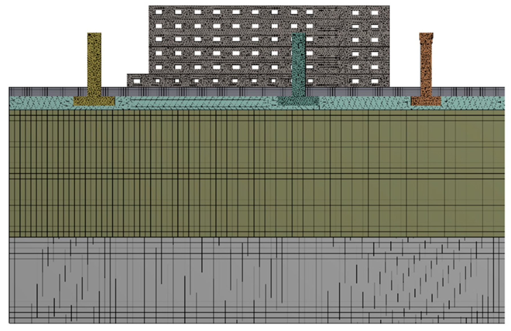
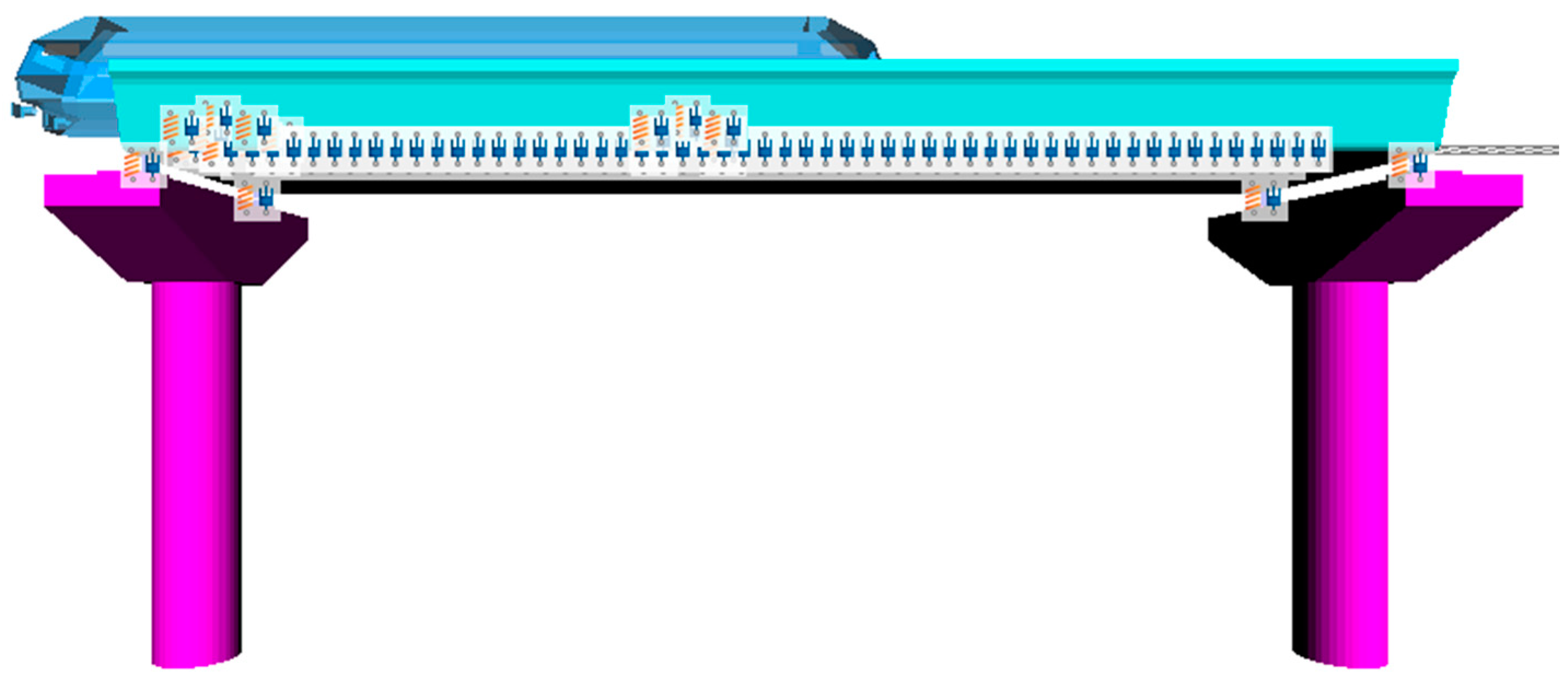
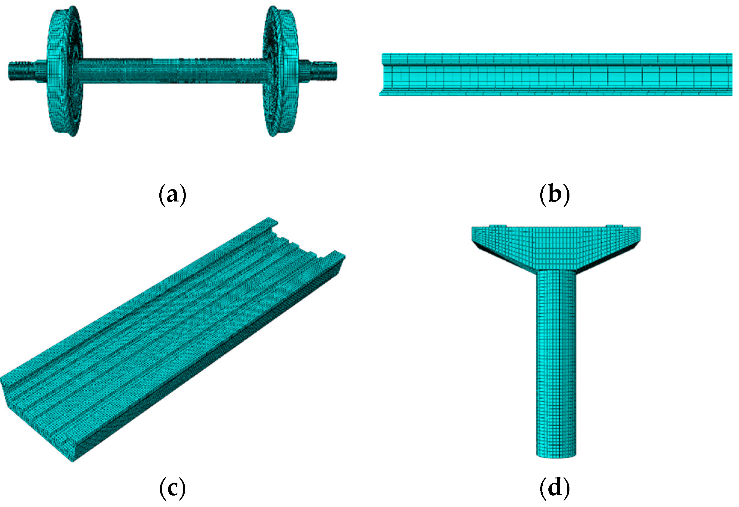
2.2. Transmission Path Model

The finite element software Workbench (v.17.0) was used to establish the pier–soil–building finite element model as a transmission path model, and the dynamic force of the pier calculated by the vibration source model was used as an input and loaded into the pier–soil–building finite element model.
In the process of research, these special characteristics of the soil medium should be taken into account. When the soil medium is basically in the range of elastic deformation under some specific conditions, it can be treated as an elastic medium and the fluctuation law of elastic mediums can be applied directly. Because the deformation caused by subway vibration is a small deformation, the elastic principal relationship is used for simulation. According to the provided soil dynamics parameters and based on the related research, four layers of soil bodies were established, and the material parameters of each soil layer are shown in Table 3.
The study shows that the ground vibration decreases as the distance of the building from the track centerline increases. In this paper, we only study the buildings at the nearest distance from the centerline of the track and establish the following geometric model and finite element model according to the building of the sensitive point and the location information of the corresponding bridge piers.
The soil model is 109 m × 60 m × 50 m. the building has a floor height of 3 m and 6 floors. The closest distance between the building and the centerline of the track is about 18.5 m. Figure 5 shows the geometric model of the pier–soil–buildings, which is a 1/2 model with symmetric boundary conditions in order to reduce the amount of calculation.
Figure 6 shows the corresponding pier–soil–building finite element model. When the cell length is divided Δ x = λ s min / 12 , the results are more accurate; when the cell length is divided Δ x = λ s min / 6 , the accuracy of the calculation can be guaranteed beyond 0.5 λ s min of the vibration source. The grid size is divided according to Equation (3):
l < C s 6 f max
where l—Size of model meshing cells (m);
Cs—Shear wave velocity of the soil layer (m/s);
fmax—maximum frequency analyzed (Hz).
Figure 6. Pier–soil–building finite element model.
Applsci 14 06706 g006
A calculation according to Equation (3) can be obtained: l < C s 6 f max = 201 6 × 80 = 0.41875 m, taking the grid size of 0.3 m. If all cells in the model are divided according to 0.3 m, a large number of cells will be generated, which will seriously affect the efficiency of the calculation. Under the premise of ensuring the correct results, the grid size of the vibration source region is controlled as 0.3 m, and the grid size can be relaxed accordingly in the region farther away from the vibration source. The final overall grid number of the model is 674,397 and the number of nodes is 2,107,071.

3. Numerical Results and Discussion

The subway line’s total length is 23 km, including 16 stations, vehicle sections, etc., basically all sections of the elevated mode. The line runs through the residential, commercial, and administrative areas, and the line runs near the existence of more sensitive points of vibration and noise; this paper focuses on the most stringent ground vibration requirements of a large hospital, as shown in Figure 7. The building is a concrete frame structure, six floors above ground, and the nearest distance between the building and the centerline of the line to be constructed is 18.5 m. The maximum speed of trains in this area is 80 km/h, and the minimum speed is 50 km/h.
According to the requirements of the local document, the ground vibration velocity limit in the area is 0.05 mm/s, which requires that when the train passes through the building, the ground vibration speed at a distance of 0.5 m from the building should not exceed 0.05 mm/s. The vibration velocity results are taken as the mean-square velocity of 1 s in the time period of the largest vibration velocity.
Because the maximum speed of the train in this area is 80 km/h, the minimum speed is 50 km/h, in order to explore the ground vibration caused by the train running to meet the requirements of the limit value of the region. Therefore, in this paper, numerical simulation is carried out for the average speed of 65 km/h of train operation. At the initial stage of design, the parameters of the fasteners used were 12.0 × 10⁶ N/m for vertical stiffness, 13.5 × 10⁶ N/m for lateral stiffness, 1361.12 Ns/m for vertical damping, and 947.27 Ns/m for lateral damping.
Figure 8 gives the time and frequency domain results of ground vibration under the fastener 1 scheme when the vehicle speed is 65 km/h. The result of ground vibration under this scheme is 0.08 mm/s, which does not meet the vibration limit

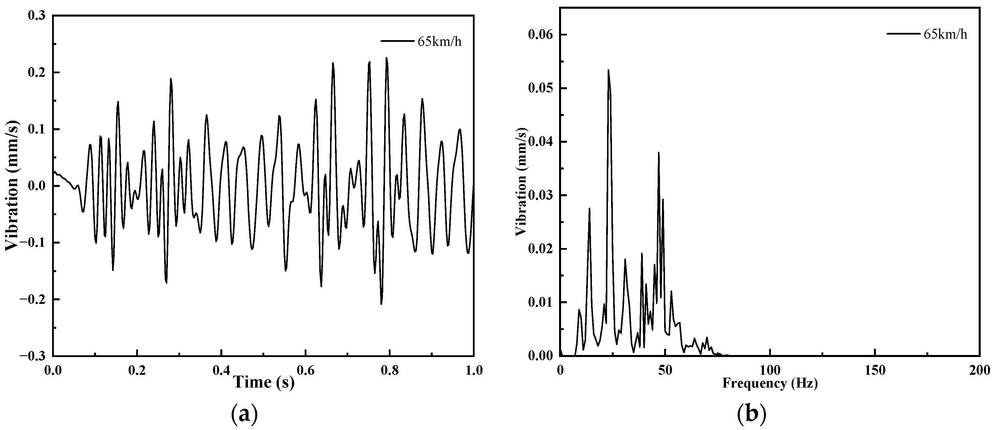
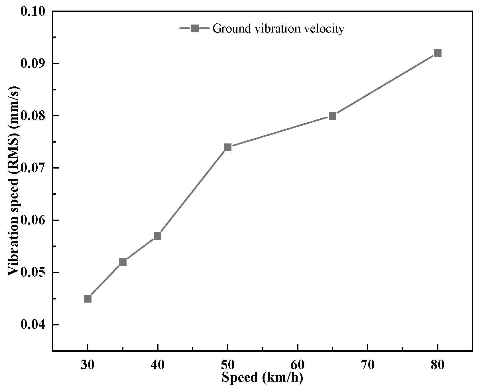
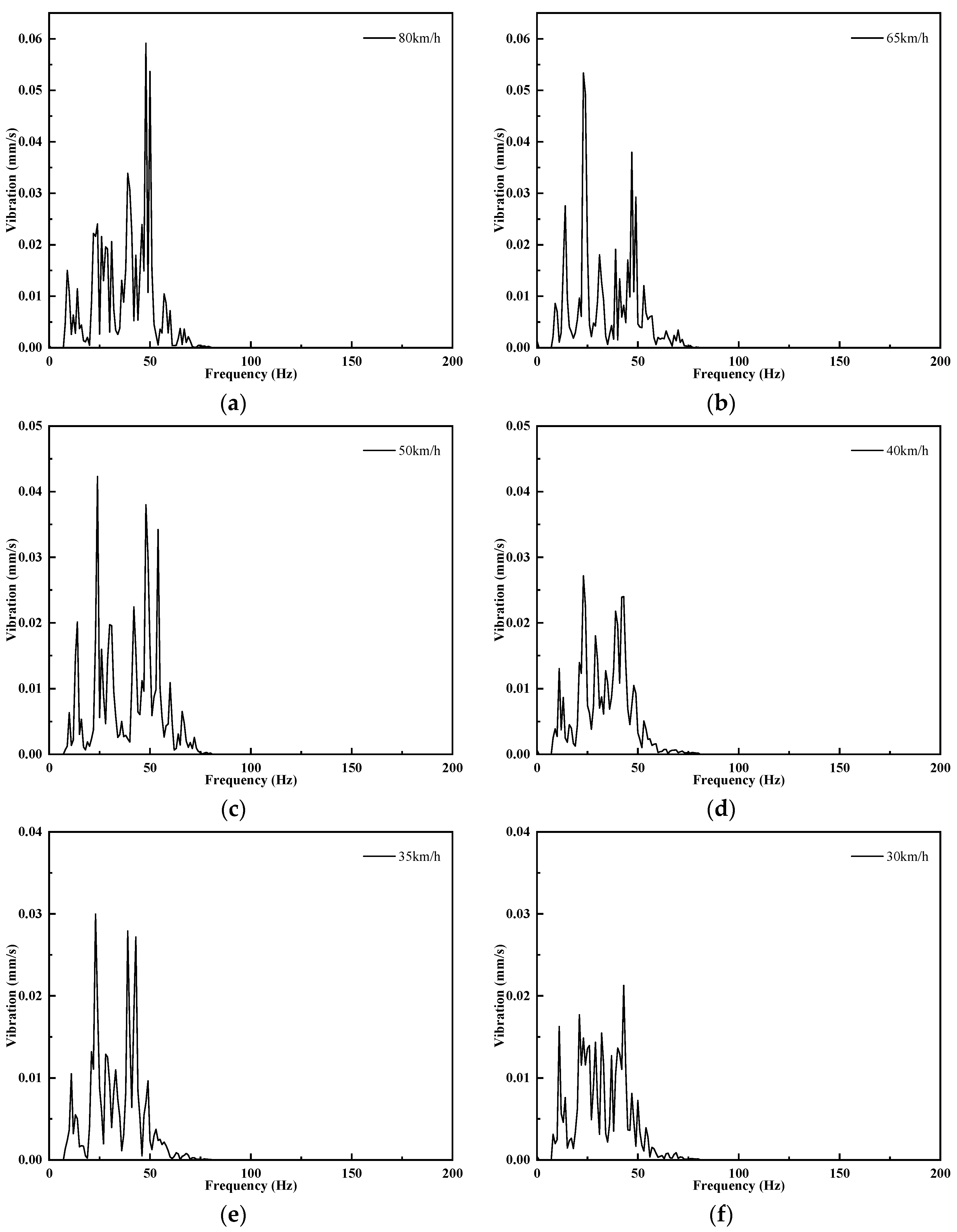
3.1. Effect of Vehicle Speed on Ground Vibration

When the train is running at 65 km/h, the ground vibration does not meet the requirements of the ground vibration limit. In the case of only changing the train speed, the ground vibration results of different speeds are investigated through simulation calculations. The simulated speeds are 80 km/h, 65 km/h, 50 km/h, 40 km/h, 35 km/h, and 30 km/h. The time domain results of ground vibration speeds for different speed scenarios are given in Figure 9.
With the vehicle running speed from 30 km/h to 80 km/h, the trend of the time domain results is consistent. As the speed decreases, the ground vibration velocity shows a decreasing trend, and the peak velocity of ground vibration also decreases with the reduction in train running speed. When the speed is reduced to 40 km/h, the vibration speed attenuation is more obvious, and as the speed continues to reduce, the vibration attenuation is slower. Figure 10 gives the results of ground vibration speed at different speeds. It can be seen from the figure that for the train running speed from 50 km/h down to 40 km/h, the ground vibration attenuation is most obvious.
Table 4 gives the ground vibration speed results from 30 km/h to 80 km/h. When the train runs 30 km/h, the ground vibration result is 0.045 mm/s, and at this time, the ground vibration speed result meets the limit value requirements.
The frequency domain results of ground vibration velocity at different train operating speeds are given in Figure 11. The frequency domain results show that the amplitude of ground vibration shows a decreasing trend as the speed decreases. The vibration peak value decreases with the reduction in the speed of the train, the vibration peak value is at 48 Hz when the train is running at 80 km/h, and the vibration peak value is at 23 Hz when the train speed is 60 km/h, 50 km/h, 40 km/h, and 35 km/h. The ground vibration is mainly concentrated at 8–50 Hz.

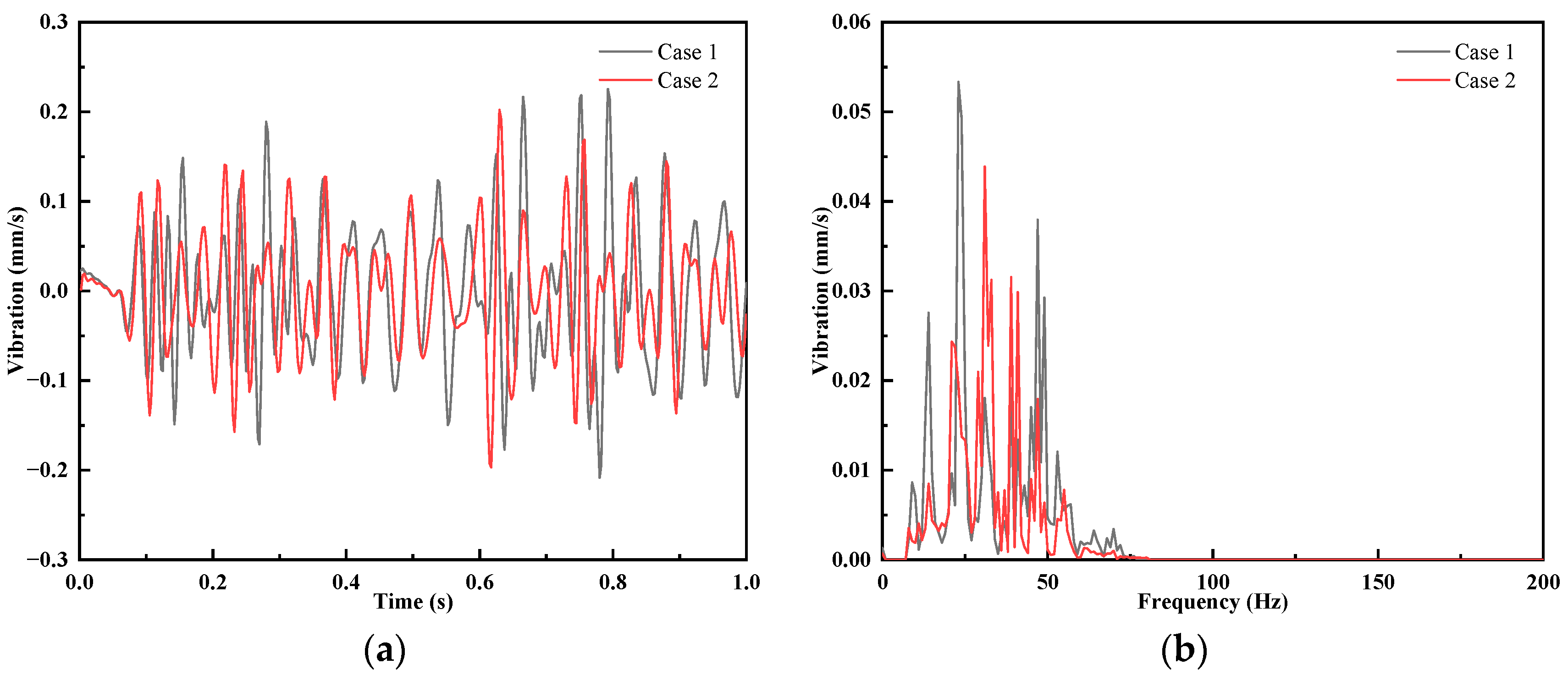
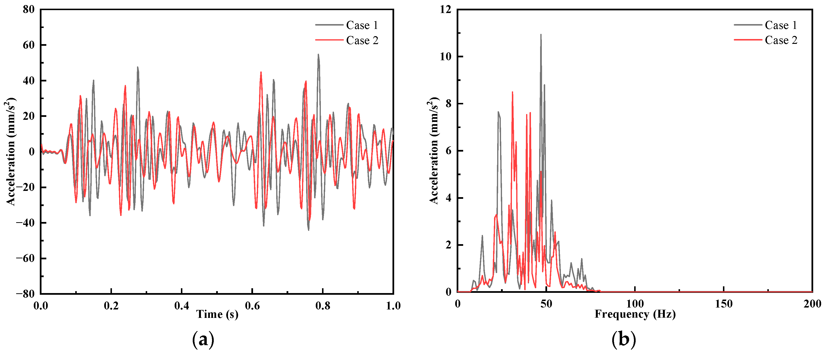
3.2. Effect of Fastener Stiffness on Ground Vibration

The vibration velocity decreases from 0.08 mm/s to 0.07 mm/s when the train is running at 65 km/h. The time domain results and frequency domain results of the ground vibration velocity with different fasteners are shown in Figure 12. From Figure 12, it can be seen that as the vertical stiffness of the fasteners decreases, the trend of the time domain results of the ground vibration velocity is consistent and the vibration peak decreases. The frequency domain results show that the ground vibration is mainly concentrated at 8–50 Hz, the peak vibration value decreases, and the peak vibration frequency shifts from 23 Hz to 31 Hz.
The parameters of different vibration-reducing fasteners and the results of ground vibration are shown in Table 5. The vibration velocity under two kinds of vibration-reducing fasteners still cannot satisfy the vibration limit requirements.
The RMS value of ground vibration acceleration can be obtained according to ISO 2631 [32] as shown in the following equation:
a w , e = [ a w i 2 . T i T i ] 1 2
where aw,e is the equivalent vibration quantity (root-mean-square acceleration in m/s2), and awi is the amount of vibration at time Ti (root-mean-square acceleration expressed in m/s2).
The time domain results and frequency domain results of ground vibration acceleration for different schemes are given in Figure 13.
As can be seen from Figure 13, the ground vibration acceleration tends to be consistent in the time domain, and the peak vibration acceleration decreases as the vertical stiffness of the fastener decreases. The RMS value of ground vibration acceleration is 15.63 mm/s2 when using case 1 and 13.61 mm/s2 when using case 2. The RMS value of ground vibration acceleration decreases by 2 mm/s2. In the frequency domain results, the peak acceleration decreases, but the dominant frequency of the vibration acceleration is shifted. Combined with the vibration velocity, it can be found that the values of vibration velocity and acceleration RMS have decreased, and the peak frequency of vibration velocity and acceleration has been shifted, which is not obvious for the ground vibration damping.

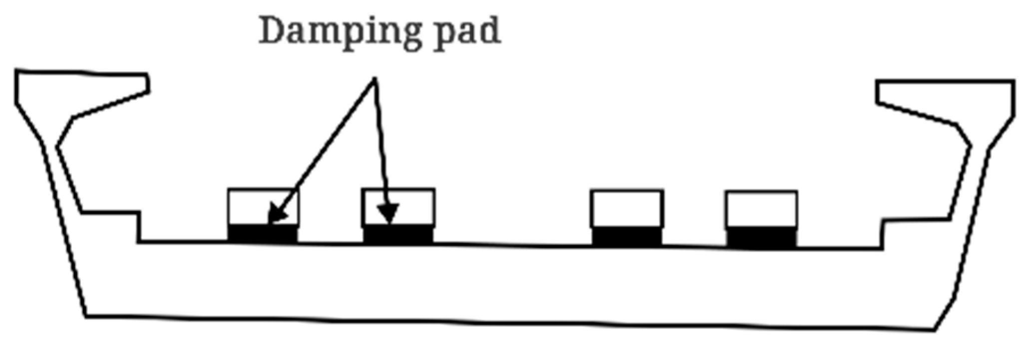
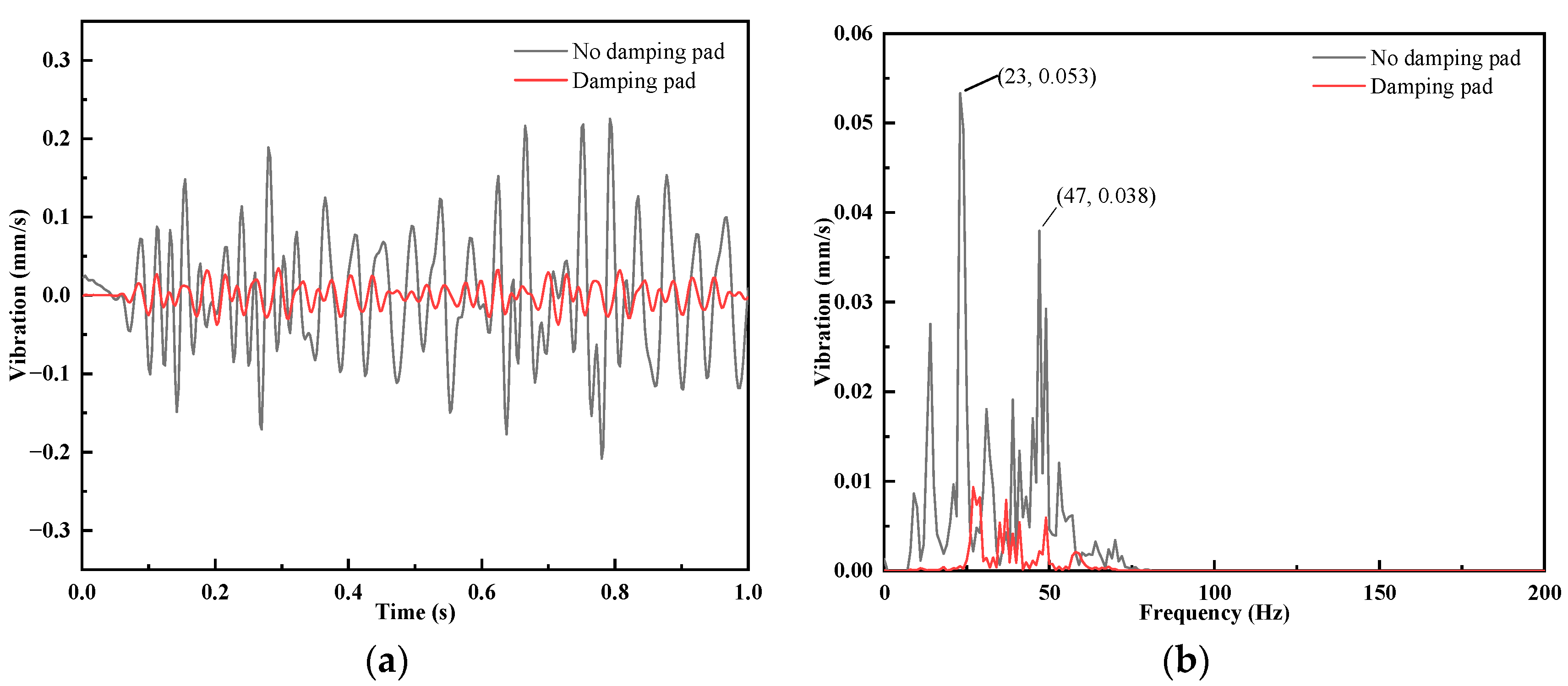
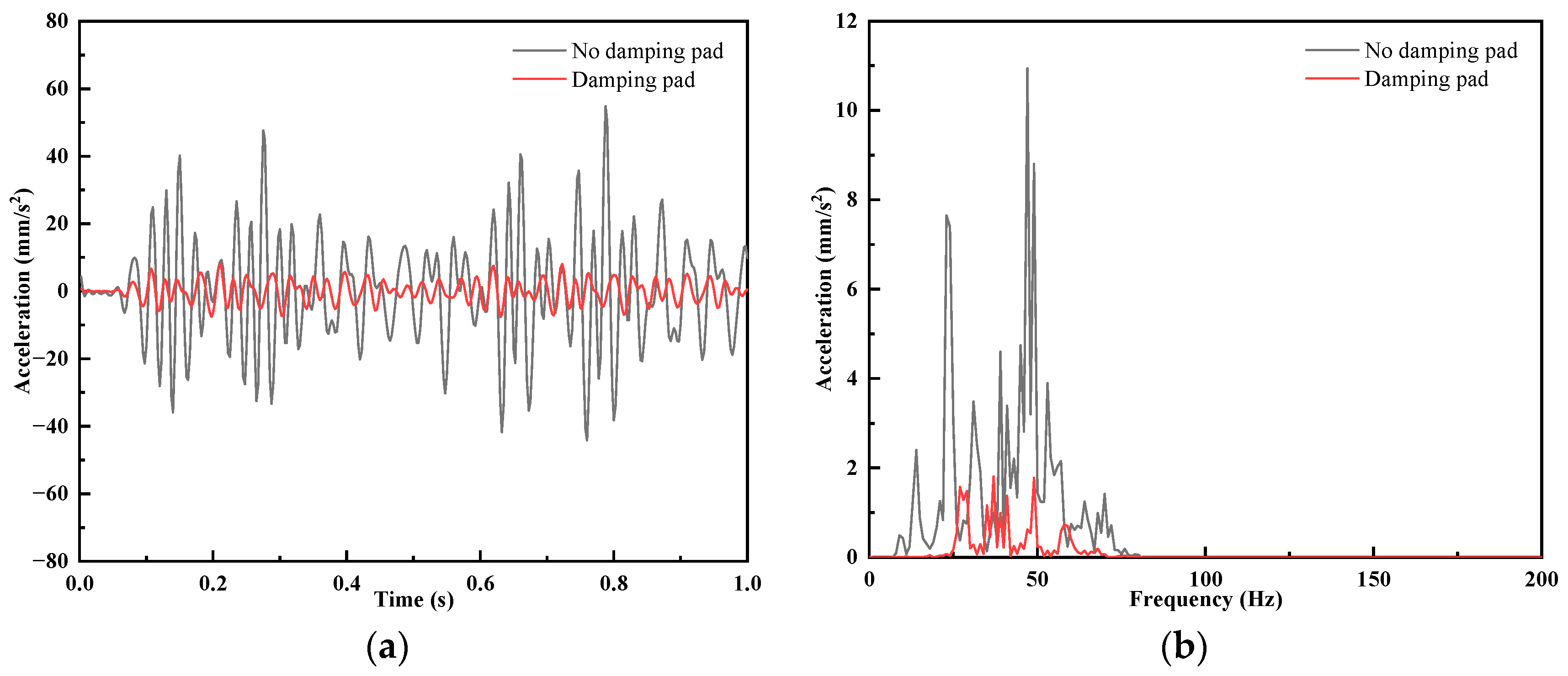
3.3. Effect of Installing Vibration Damping Pad on Ground Vibration

When the vehicle speed is 65 km/h, it can be seen from the calculation results that when using damping fasteners for vehicle running-induced ground vibration control, the ground vibration velocities are 0.08 mm/s and 0.07 mm/s, which does not meet the ground vibration limit requirements. The vibration impact of train running can be reduced by using damping pads. The vibration damping pad arrangement form is as shown in Figure 14. The damping pad has a loss angle of 0.6°, a foundation modulus of 0.019 N/mm3, and a thickness of 30 mm.
Before and after the arrangement of damping pads, the ground vibration velocity time domain results and frequency domain results are as shown in Figure 15. From the time domain results, it can be seen that after the arrangement of the vibration damping pads, the amplitude of the vibration velocity is significantly reduced; at this time, the vibration result measures 0.015 mm/s, compared with not installing vibration damping pads, and the ground vibration is effectively controlled to meet the ground vibration limit requirements. Before the installation of damping pads, the vibration peak in the frequency domain at 23 Hz had the value of 0.053 mm/s, and at 47 Hz, it had the vibration speed of 0.038 mm/s. After the installation of damping pads, the vibration speeds of 0–23 Hz and 50–80 Hz are effectively suppressed. The installation of vibration damping pads can effectively control the ground vibration generated by train running.
Figure 16 gives the time domain and frequency domain results of ground vibration acceleration before and after the installation of damping pads. From the figure, we can see that the ground vibration acceleration is effectively controlled from the time domain results after the installation of damping pads. After installing the damping pads, the RMS value of ground acceleration is reduced from 15.63 mm/s to 3.2 mm/s. At 0–80 Hz, the peak value of ground acceleration is effectively controlled after installing the damping pads. Overall, the ground vibration velocity and acceleration can be effectively controlled with the installation of vibration damping pads, which have a good vibration damping effect.

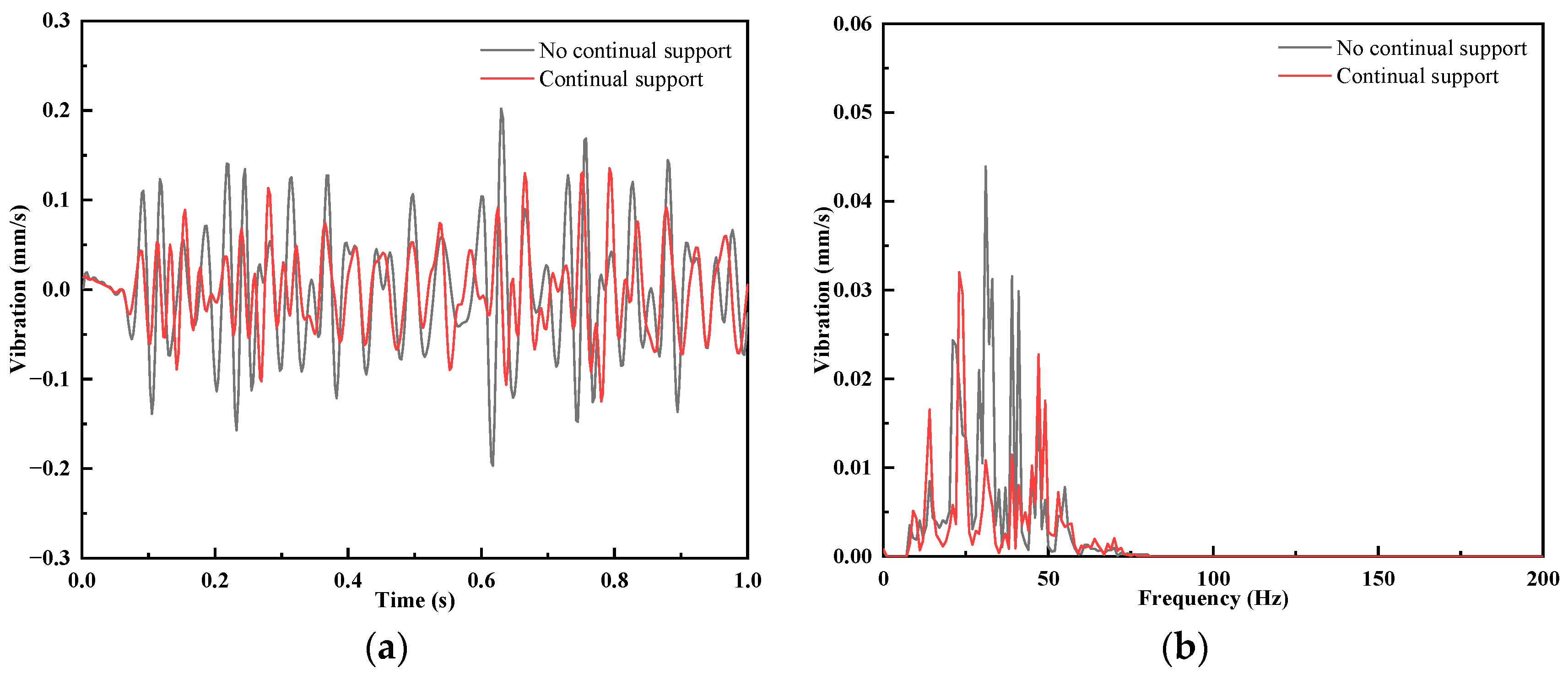
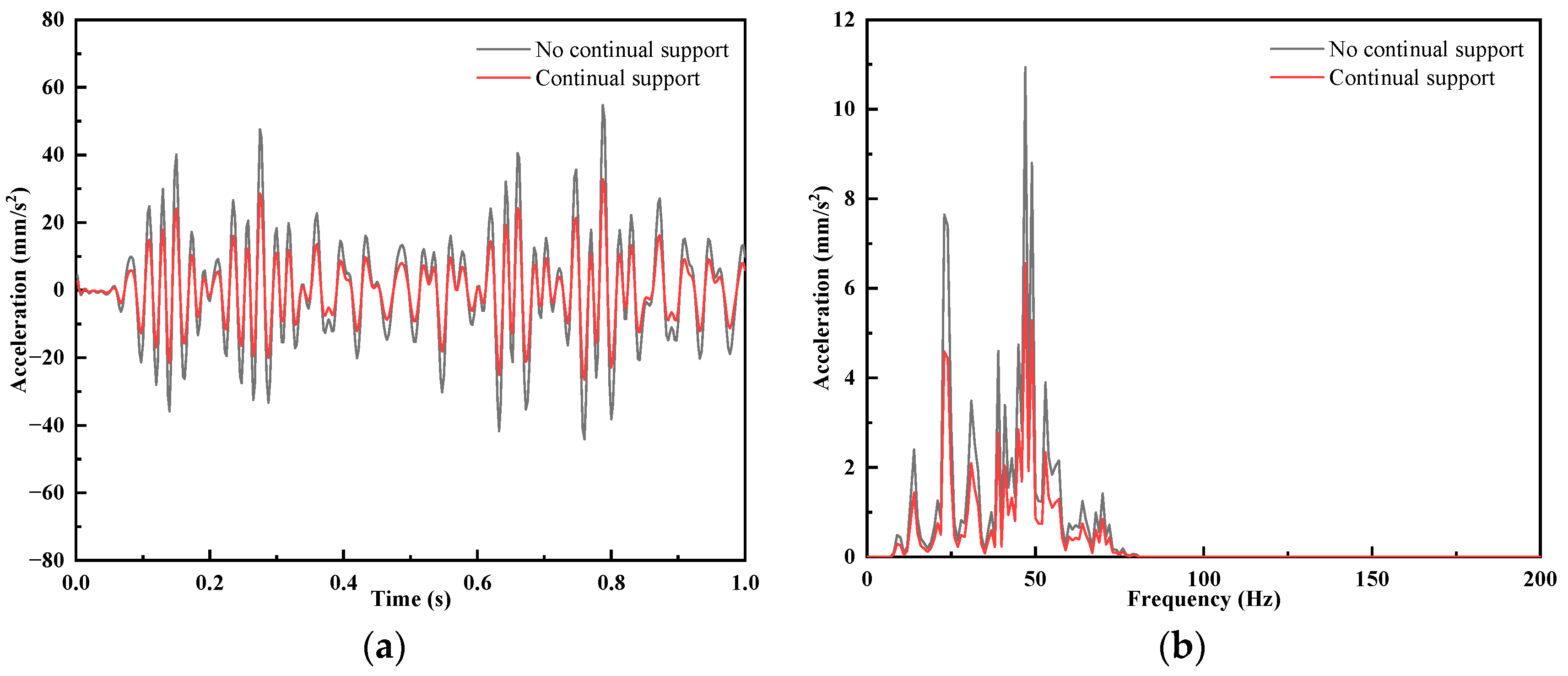
3.4. Effect of Continuous Support on Ground Vibration

The basic parameters of the continuous support vibration reduction structure are as follows: continuous support stiffness of 14 kN/mm, polymer material elastic modulus 15 MPa, loss factor 0.28, structure 0.3 m long, and total mass 21.8 kg. The parameters of the fasteners used were 10 × 106 N/m for vertical stiffness, 13.5 × 10⁶ N/m for lateral stiffness, 1361.12 Ns/m for vertical damping, and 947.27 Ns/m for lateral damping.
The time domain results and frequency domain results of the ground vibration velocity before and after the installation of the continuous support are shown in Figure 17. From the time domain results, it can be seen that the vibration velocity trend is the same after arranging the continuous support, and the vibration result of 0.048 mm/s at this time meets the ground vibration limit requirements. Before installing the continuous support, the vibration peak value in the frequency domain is larger, and the vibration velocity peak value is effectively suppressed after installing the continuous support.
From Figure 18, it can be known that after installing the continuous support, the vibration trend is the same in both the time domain and frequency domain results. In the time domain results, the vibration acceleration is reduced. After installing the continuous support, the RMS value of ground vibration acceleration is reduced from 15.63 mm/s to 9.38 mm/s. In the range of 0–80 Hz, after installing the continuous support, the peak value of ground acceleration is effectively controlled. Overall, the ground vibration velocity and acceleration can be reduced after installing the continuous support.

4. Conclusions

This paper establishes the train–track–viaduct rigid–flexible coupling dynamics model as the vibration source model and the pier–soil–building finite element model as the transmission path model, carries out a simulation study on the ground vibration caused by the metro vehicle running on the viaduct line in a nearby building, and analyzes the vibration reduction effect of the different vibration reduction schemes. The effects of train running speed, fastener stiffness, track vibration damping pads, and track continuous support on ground vibration were analyzed, and the following conclusions were made.
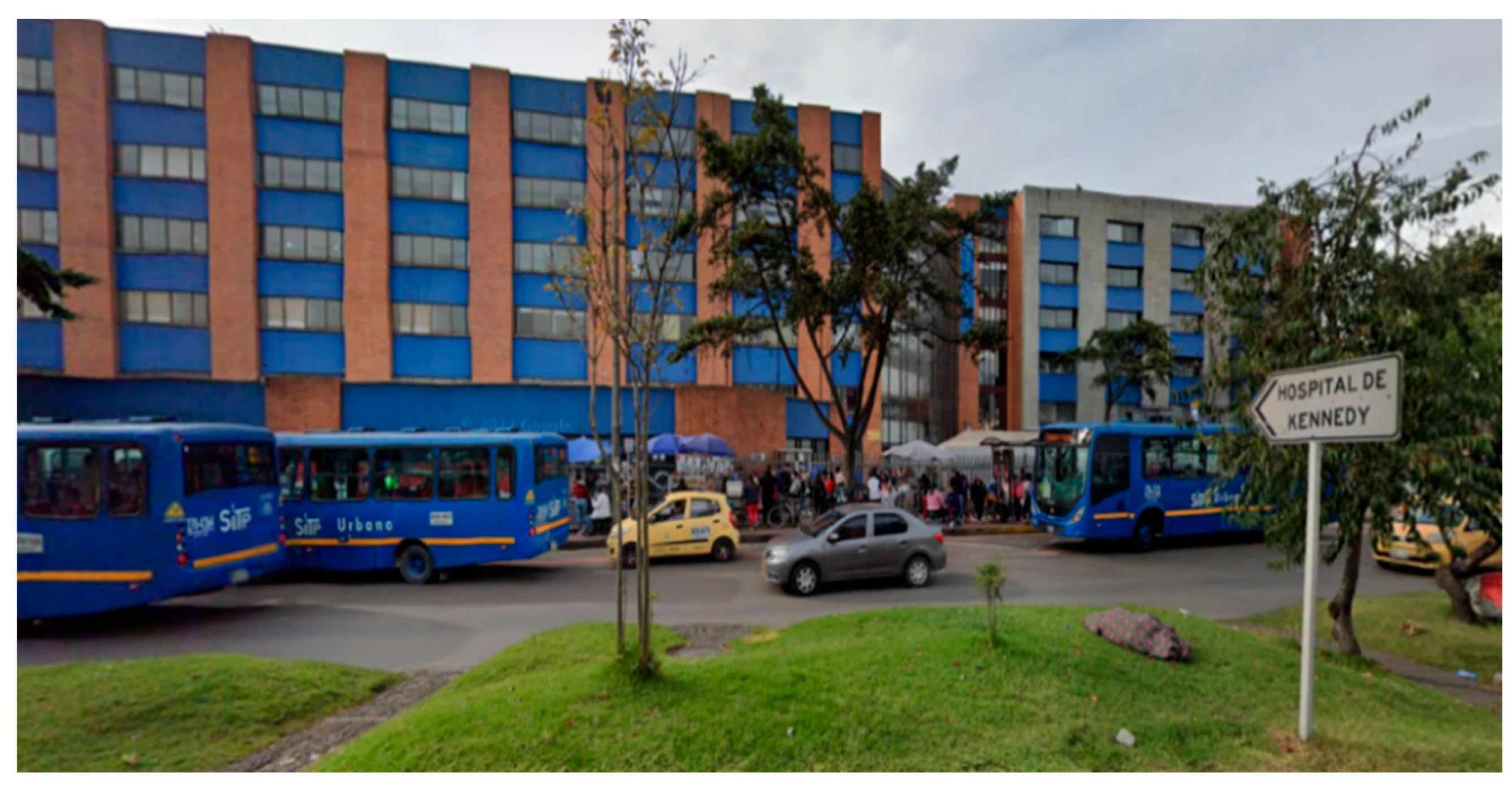
  • Because the building is close to the line, the ground vibration requirements near the building are high, and the existing line vibration reduction design cannot meet the environmental requirements.
  • When the train running speed is reduced to 30 km/h, the ground vibration can meet the environmental limit value requirements, but the actual operating speed of the train has a greater impact. When applying vibration-damping fasteners alone, the system has the best vibration-reducing performance when the vertical stiffness of fasteners is 10 kN/mm, but it still cannot meet the requirements of ground environmental limits.
  • A simulation study on the vibration reduction effect of track vibration reduction pads and a continuous support vibration reduction structure was carried out. The results show that when the vehicle running speed is 65 km/h, the vibration reduction effect of the track vibration reduction pad is outstanding, and the margin to meet the vibration limit value is larger; the vibration reduction effect of the continuous support vibration reduction structure is obvious, and the vibration reduction effect of the joint application of the fasteners and the continuous support vibration reduction structure can satisfy the vibration limit value requirement and have a reasonable margin.

Author Contributions

Conceptualization, H.W. and Z.T.; methodology, H.W.; software, L.L.; formal analysis, H.W.; investigation, X.H. and H.L.; data curation, Z.T.; writing—original draft preparation, H.W. and L.S; writing—review and editing, H.W.; visualization, H.W.; supervision, L.S. All authors have read and agreed to the published version of the manuscript.

Funding

This research received no external funding.

Institutional Review Board Statement

Not applicable.

Informed Consent Statement

Not applicable.

Data Availability Statement

The original contributions presented in the study are included in the article, and further inquiries can be directed to the corresponding author.

Conflicts of Interest

Author Hao Wang and Ziqi Tang were employed by China Harbour Engineering Company Limited. The remaining authors declare that the re-search was conducted in the absence of any commercial or financial relationships that could be construed as a potential conflict of interest.

References

  1. Connolly, D.P.; Marecki, G.P.; Kouroussis, G.; Thalassinakis, I.; Woodward, P.K. The growth of railway ground vibration problems—A review. Sci. Total Environ. 2016, 568, 1276–1282. [Google Scholar] [CrossRef] [PubMed]
  2. Tao, Z.; Wang, Y.; Zou, C.; Li, Q.; Luo, Y. Assessment of ventilation noise impact from metro depot with over-track platform structure on workers and nearby inhabitants. Environ. Sci. Pollut. Res. Int. 2019, 26, 9203–9218. [Google Scholar] [CrossRef] [PubMed]
  3. Lopes, P.; Ruiz, J.F.; Alves Costa, P.; Medina Rodriguez, L.; Cardoso, A.S. Vibrations inside buildings due to subway railway traffic. Experimental validation of a comprehensive prediction model. Sci. Total Environ. 2016, 568, 1333–1343. [Google Scholar] [CrossRef] [PubMed]
  4. Xia, H.; Zhang, N. Vibration effects of light-rail train-viaduct system on surrounding environments. In Proceedings of the 4th Conference of the Eastern-Asia-Society-for-Transportation-Studies, Hanoi, Vietnam, 24–27 October 2001. [Google Scholar]
  5. Vogiatzis, K.; Zafiropoulou, V.; Mouzakis, H. Monitoring and assessing the effects from Metro networks construction on the urban acoustic environment: The Athens Metro Line 3 Extension. Sci. Total Environ. 2018, 639, 1360–1380. [Google Scholar] [CrossRef] [PubMed]
  6. Sadeghi, J.; Esmaeili, M.H.; Akbari, M. Reliability of FTA general vibration assessment model in prediction of subway induced ground borne vibrations. Soil Dyn. Earthq. Eng. 2019, 117, 300–311. [Google Scholar] [CrossRef]
  7. Zou, C.; Wang, Y.; Wang, P.; Guo, J. Measurement of ground and nearby building vibration and noise induced by trains in a metro depot. Sci. Total Environ. 2015, 536, 761–773. [Google Scholar] [CrossRef] [PubMed]
  8. Paneiro, G.; Durão, F.O.; Costa e Silva, M.; Falcão Neves, P. Prediction of ground vibration amplitudes due to urban railway traffic using quantitative and qualitative field data. Transp. Res. Part D Transp. Environ. 2015, 40, 1–13. [Google Scholar] [CrossRef]
  9. Sheng, X. A review on modelling ground vibrations generated by underground trains. Int. J. Rail Transp. 2019, 7, 241–261. [Google Scholar] [CrossRef]
  10. Xing, M.; Zhao, C.; Wang, P.; Lu, J.; Yi, Q. A Numerical Analysis of Ground Vibration Induced by Typical Rail Corrugation of Underground Subway. Shock Vib. 2019, 2019, 8406813. [Google Scholar] [CrossRef]
  11. Kedia, N.K.; Kumar, A.; Singh, Y. Development of Empirical Relations to Predict Ground Vibrations due to Underground Metro Trains. KSCE J. Civ. Eng. 2023, 27, 251–260. [Google Scholar] [CrossRef]
  12. Xu, L.; Ma, M. Vibration amplification zone phenomenon on the ground surface under various types of buried dynamic loads within metro tunnel. Soil Dyn. Earthq. Eng. 2024, 182, 108713. [Google Scholar] [CrossRef]
  13. Li, Z.; Yang, X.; Zhang, S.; Yu, Y.; Lin, Y.; Wu, J. Analysis of Soil Differences in Subway Vibration Transmission Paths. Buildings 2024, 14, 1338. [Google Scholar] [CrossRef]
  14. Ma, L.X.; Yu, Y.X.; Li, H.Y.; Yang, H. Investigation of Metro Train-Induced Environmental Vibration Using a Coupled Sliced Finite Element-Infinite Element Model. KSCE J. Civ. Eng. 2024, 28, 2380–2398. [Google Scholar] [CrossRef]
  15. Deng, E.; Liu, X.-Y.; Ni, Y.-Q.; Wang, Y.-W.; Zhao, C.-Y. A coupling analysis method of foundation soil dynamic responses induced by metro train based on PDEM and stochastic field theory. Comput. Geotech. 2023, 154, 105180. [Google Scholar] [CrossRef]
  16. Ma, M.; Xu, L.; Liu, W.; Tan, X. Semi-analytical solution of a coupled tunnel-soil periodic model with a track slab under a moving train load. Appl. Math. Model. 2024, 128, 588–608. [Google Scholar] [CrossRef]
  17. He, Y.; Zhang, Y.; Yao, Y.; He, Y.; Sheng, X. Review on the Prediction and Control of Structural Vibration and Noise in Buildings Caused by Rail Transit. Buildings 2023, 13, 2310. [Google Scholar] [CrossRef]
  18. Wang, S.; Zhu, S. Impact source localization and vibration intensity prediction on construction sites. Measurement 2021, 175, 109148. [Google Scholar] [CrossRef]
  19. Cheng, Z.; Zhang, Q.; Shi, Z. Floating slab track with inerter enhanced dynamic vibration absorbers. Veh. Syst. Dyn. 2023, 61, 589–615. [Google Scholar] [CrossRef]
  20. Sheng, T.; Bian, X.-c.; Xiao, C.; Chen, Y.; Liu, G.-b.; Li, Y. Experimental study on a geosynthetics isolator for the base vibration isolation of buildings neighboring metro transportation. Geotext. Geomembr. 2021, 49, 1066–1078. [Google Scholar] [CrossRef]
  21. Sun, X.; Ma, M.; Jiang, B.; Cao, R. Ground vibration from freight railway: Environmental impact and potential mitigation measure at propagation path. Environ. Sci. Pollut. Res. 2022, 29, 44364–44377. [Google Scholar] [CrossRef]
  22. He, W.; Zou, C.; Pang, Y.T.; Wang, X.M. Environmental noise and vibration characteristics of rubber-spring floating slab track. Environ. Sci. Pollut. Res. 2021, 28, 13671–13689. [Google Scholar] [CrossRef]
  23. Thompson, D.; Jones, C. Reply to Comments on Chapter 12 of “Railway Noise and Vibration: Mechanisms, Modelling and Means of Control”, by D. Thompson (with contributions from C. Jones and P.-E. Gautier), Elsevier, 2009. Appl. Acoust. 2011, 72, 787–788. [Google Scholar] [CrossRef]
  24. Alves Costa, P.; Calçada, R.; Silva Cardoso, A. Ballast mats for the reduction of railway traffic vibrations. Numerical study. Soil Dyn. Earthq. Eng. 2012, 42, 137–150. [Google Scholar] [CrossRef]
  25. Yang, J.; Zhu, S.; Zhai, W.; Kouroussis, G.; Wang, Y.; Wang, K.; Lan, K.; Xu, F. Prediction and mitigation of train-induced vibrations of large-scale building constructed on subway tunnel. Sci. Total Environ. 2019, 668, 485–499. [Google Scholar] [CrossRef] [PubMed]
  26. Hou, B.W.; Gao, L.; Xin, T.; Cai, X.P. Prediction of structural vibrations using a coupled vehicle-track-building model. Proc. Inst. Mech. Eng. Part F-J. Rail Rapid Transit 2016, 230, 510–530. [Google Scholar] [CrossRef]
  27. Guo, T.; Cao, Z.; Zhang, Z.; Li, A. Numerical simulation of floor vibrations of a metro depot under moving subway trains. J. Vib. Control 2017, 24, 4353–4366. [Google Scholar] [CrossRef]
  28. Zhao, C.; Shi, D.; Zheng, J.; Niu, Y.; Wang, P. New floating slab track isolator for vibration reduction using particle damping vibration absorption and bandgap vibration resistance. Constr. Build. Mater. 2022, 336, 127561. [Google Scholar] [CrossRef]
  29. Li, Z.; Ma, M.; Liu, K.; Jiang, B. Performance of rubber-concrete composite periodic barriers applied in attenuating ground vibrations induced by metro trains. Eng. Struct. 2023, 285, 116027. [Google Scholar] [CrossRef]
  30. Wang, C.; Wang, J.; Chen, H.; Ou, J. Mitigating train-induced building vibrations with rubber bearings designed for horizontal earthquake isolation. J. Build. Eng. 2024, 89, 109251. [Google Scholar] [CrossRef]
  31. Wang, T.; Jiang, B.; Sun, X. Train-Induced Vibration Prediction and Control of a Metro Depot and Over-Track Buildings. Buildings 2023, 13, 1995. [Google Scholar] [CrossRef]
  32. ISO 2631-1:1997; Mechanical Vibration and Shock e Evaluation of Human Exposure to Whole-body Vibration e Part 1: General Requirements. WHO: Geneva, Switzerland, 1997.
Figure 1. Train–track–viaduct rigid–flexible coupling dynamics model.
Applsci 14 06706 g001
Figure 2. Vehicle system dynamics visualization model.
Applsci 14 06706 g002
Figure 3. Flexible body components: (a) wheelset; (b) rail; (c) U-type bridge; (d) pier.
Applsci 14 06706 g003
Figure 4. Schematic diagram of model connection.
Applsci 14 06706 g004
Figure 5. Pier–soil–building geometric modeling: (a) front view; (b) side view.
Applsci 14 06706 g005
Figure 7. Sensitive site: Hospital.
Applsci 14 06706 g007
Figure 8. Ground vibration results: (a) time domain result; (b) frequency domain result.
Applsci 14 06706 g008
Figure 9. Ground vibration velocity time domain: (a) speed 80 km/h; (b) speed 65 km/h; (c) speed 50 km/h; (d) speed 40 km/h; (e) speed 35 km/h; (f) speed 30 km/h.
Applsci 14 06706 g009
Figure 10. Ground vibration velocity trends with speed.
Applsci 14 06706 g010
Figure 11. Ground vibration velocity frequency domain: (a) speed 80 km/h; (b) speed 65 km/h; (c) speed 50 km/h; (d) speed 40 km/h; (e) speed 35 km/h; (f) speed 30 km/h.
Applsci 14 06706 g011
Figure 12. Ground vibration results under different vibration reduction schemes: (a) time domain results; (b) frequency domain results.
Applsci 14 06706 g012
Figure 13. Ground vibration acceleration results under different vibration reduction schemes: (a) time domain results; (b) frequency domain results.
Applsci 14 06706 g013
Figure 14. Schematic diagram of vibration damping pad arrangement.
Applsci 14 06706 g014
Figure 15. Ground vibration results before and after installation of damping pad: (a) time domain results; (b) frequency domain results.
Applsci 14 06706 g015
Figure 16. Ground vibration acceleration results before and after installation of damping pad: (a) time domain results; (b) frequency domain results.
Applsci 14 06706 g016
Figure 17. Ground vibration results before and after the installation of continuous support: (a) time domain results; (b) frequency domain results.
Applsci 14 06706 g017
Figure 18. Ground vibration acceleration results before and after installation of continuous support: (a) time domain results; (b) frequency domain results.
Applsci 14 06706 g018
Table 1. Vehicle structural parameters.
Parameter NameNumerical ValueUnit
Mass of car body49.52t
Mass moment of inertia of car body roll80t·m2
Mass moment of inertia of car body pitch1836t·m2
Mass moment of inertia of car body yaw1835t·m2
Car body center of gravity coordinates2.056m
Mass of bogie4387kg
Mass moment of inertia of car body yaw1847.4kg·m2
Mass moment of inertia of car body yaw3903.8kg·m2
Mass moment of inertia of car body yaw5583.4kg·m2
Mass of wheelset1443kg
Longitudinal stiffness of primary suspension5.2MN/m
Lateral stiffness of primary suspension5.2MN/m
Vertical stiffness of primary suspension0.95MN/m
Longitudinal damping of primary suspension15kN·s/m
Lateral damping of primary suspension2kN·s/m
Vertical damping of primary suspension20kN·s/m
Longitudinal stiffness of secondary suspension0.148MN/m
Lateral stiffness of secondary suspension0.148MN/m
Vertical stiffness of secondary suspension0.452MN/m
Longitudinal damping of secondary suspension50kN·s/m
Lateral damping of secondary suspension32kN·s/m
Vertical damping of secondary suspension32kN·s/m
Table 2. Component parameters.
ComponentDensity (kgm−3)Elastic Modulus (GPa)Poisson’s Ratio
Wheelset78002060.3
Steel rail78002060.3
U-shaped bridge2450370.2
Pier2450370.2
Table 3. Soil material properties.
Soil LayerDensity (kgm−3)Poisson’s RatioShear Wave Velocity (m/s)Shear Modulus (GPa)Elastic Modulus (GPa)
First layer19300.351300.1020.276
Second layer18500.352600.1340.363
Third layer18410.362700.1340.365
Fourth layer18390.352010.0720.200
Table 4. Ground vibration velocity at different vehicle speeds.
SchemeSpeed (km/h)Distance (m)Vibration Velocity (mm/s)Vibration Velocity Limits (mm/s)
18018.50.0920.05
26518.50.080.05
35018.50.0740.05
44018.50.0570.05
53518.50.0520.05
63018.50.0450.05
Table 5. Calculation results of ground vibration under different fasteners.
SchemeSpeed (km/h)Fastener parametersVibration Velocity (mm/s)
Vertical
Stiffness (N/m)
Lateral Stiffness (N/m)Vertical Damping (Ns/m)Lateral Damping (Ns/m)
Case 16512.07 × 10613.5 × 1061361.12947.270.08
Case 26510 × 10632 × 1061861.121474.270.07
Disclaimer/Publisher’s Note: The statements, opinions and data contained in all publications are solely those of the individual author(s) and contributor(s) and not of MDPI and/or the editor(s). MDPI and/or the editor(s) disclaim responsibility for any injury to people or property resulting from any ideas, methods, instructions or products referred to in the content.

