Article

Ultimate Support Pressure Determination for Shield Tunnel Faces in Saturated Strata Based on Seepage Flow Control

1
School of Civil Engineering, Central South University, Changsha 410075, China
2
Key Laboratory of Engineering Structure of Heavy Haul Railway, Changsha 410075, China
*
Author to whom correspondence should be addressed.
Appl. Sci. 2024, 14(15), 6781; https://doi.org/10.3390/app14156781 (registering DOI)
Submission received: 15 July 2024 / Revised: 31 July 2024 / Accepted: 1 August 2024 / Published: 3 August 2024
(This article belongs to the Special Issue Advances in Tunnelling and Underground Space Technology)

Abstract

:
Existing methods for calculating the ultimate support pressure of tunnel faces do not consider the control of seepage flow. Therefore, a model for calculating the ultimate support pressure under seepage conditions was established based on a two-dimensional water head distribution model and the upper bound theorem of limit analysis. The reliability of this method was verified through comparisons with other studies. Subsequently, the influence of water level and tunnel face water pressure coefficient on stability was analyzed. The results indicate that the ultimate support pressure is linearly positively correlated with the water level and tunnel face water pressure coefficient; as the water level increases and the water pressure coefficient decreases, the failure area extends and enlarges. Finally, an existing seepage flow calculation formula was introduced, and a method for calculating the ultimate support pressure based on seepage control was proposed. The appropriate tunnel face water pressure coefficient is determined through the seepage flow calculation formula, and the corresponding ultimate support pressure is then calculated. The results demonstrate that this method can provide better theoretical guidance for seepage control in tunnel faces in practical engineering.

1. Introduction

To address the traffic congestion caused by population growth and rapid urbanization, urban subways have developed rapidly [1,2,3]. Throughout the construction of urban subways, the shield tunneling method has occupied a significant market share [4,5]. To ensure the safety of shield tunneling, extensive research has been conducted on various aspects of shield tunnel construction with the stability of the tunnel face being one of the hotspots [6,7,8]. Research methods include numerical simulations [9,10], experimental tests [11,12], and theoretical analyses [13,14]. As a theoretical method, limit analysis is favored by scholars for its efficiency in parameter analysis [15,16,17]. Particularly, with the introduction of spatial discretization techniques, this method can cover the entire circular failure mechanism, leading to increasingly accurate results [18].
During shield tunneling in water-rich strata, the tunnel face is subjected to combined effects of earth pressure, buoyancy, and seepage forces, significantly increasing the risk of instability and the complexity of stability analysis [19,20]. This has led many scholars to focus on the stability analysis of the tunnel face under water-rich conditions, particularly on how to account for seepage factors [21,22]. For example, calculating the distribution of the water head through pure seepage analysis using numerical software is an effective method [23]. Studies have shown that when the soil’s permeability coefficient is greater than 10−6 to 10−7 m/s and the tunneling speed is less than 0.1 to 1.0 m/h, using saturated steady-state seepage can meet the accuracy requirements for tunnel face stability analysis [24]. On the basis of accurate calculations from numerical analysis, some simplified calculation methods have been proposed, such as empirical formulas and analytical methods combining numerical results [25,26]. Based on these methods, the stability of the tunnel face under seepage conditions has been widely studied, seemingly solving the problem perfectly. However, existing studies often assume the water pressure at the tunnel face to be zero, while DI’s research indicates that the water pressure is usually not zero and has a significant impact on the stability of the tunnel face [27,28]. DI’s research highlighted common issues in existing studies and provided insights for future research but unfortunately did not provide a method for determining the water pressure at the tunnel face.
In fact, after the tunnel face is exposed, the water pressure on the tunnel face directly affects the nearby seepage field, resulting in changes in seepage flow at the tunnel face. Therefore, to control the seepage flow at the tunnel face, it is necessary to apply the required earth and water pressure through the shield. From the parameter selections in existing studies, it is evident that the assumption of zero water pressure at the tunnel face is mainly applied to low-permeability strata. In such strata, the seepage flow is minimal, and not setting water pressure at the tunnel face does not lead to water inflow incidents [29,30]. However, in highly permeable strata, failing to determine reasonable water pressure at the tunnel face can easily cause water inflow and even lead to engineering accidents.
Therefore, this paper first establishes the relationship between water pressure and seepage flow at the tunnel face by calculating the seepage flow at the tunnel face, obtaining a reasonable water pressure at the tunnel face based on seepage flow control. Furthermore, a method for calculating the distribution of pore water pressure in front of the tunnel face is derived based on the analytical methods of the three-dimensional seepage field. By introducing the seepage flow calculation equation, a method for calculating the pore water pressure distribution based on seepage flow control is proposed. On this basis, an ultimate support pressure calculation model for the tunnel face in water-saturated strata is constructed using the upper bound theorem of limit analysis, and the stability of the tunnel face under seepage conditions is analyzed. Finally, by combining seepage flow control with earth stability control, a method for determining the ultimate support pressure of the shield tunnel face in water-saturated strata based on seepage flow control is proposed.

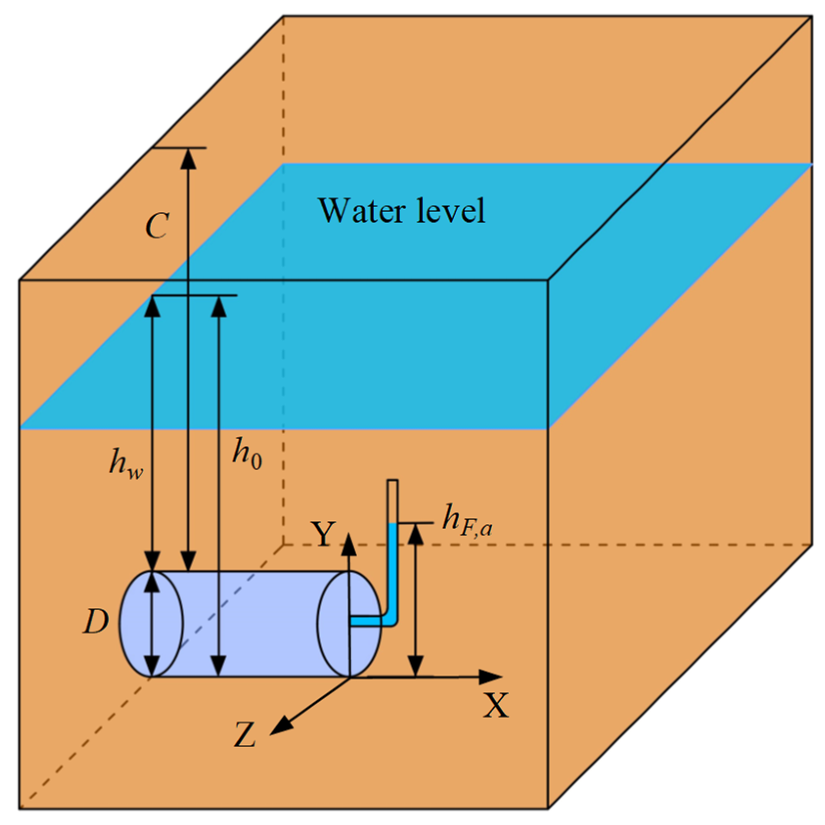
2. Problem Statement

Currently, most studies set the water head at the tunnel face to zero (i.e., atmospheric pressure) when calculating seepage at the tunnel face [24,25,26]. This setting is reasonable when the permeability coefficient of the strata is low because the seepage flow is limited even if the water pressure at the tunnel face is zero. However, as the permeability coefficient of the strata increases and the water head rises, setting the water pressure at the tunnel face to zero will result in a large seepage flow, which in turn affects the stability of the tunnel face. Therefore, seepage flow control at the tunnel face must be considered in seepage analysis.
As shown in Figure 1, for a tunnel with an excavation diameter of D, a cover depth of C, and a groundwater level depth of (C-hw), with the tunnel bottom as the reference water head plane, seepage will occur at the tunnel face when the water head at the tunnel face is less than h0 (h0 being the vertical distance from the groundwater level to the tunnel bottom).
For estimating the seepage flow at the tunnel face, Bear [31] proposed a method using circular equipotential surfaces. Subsequently, Zhang Yu [32] extended this method to three-dimensional analysis and derived a formula for calculating the seepage flow at the shield tunnel face. For the estimation of seepage flow at the tunnel face in water-rich strata, as shown in Figure 1, a simple transformation based on Zhang Yu’s method [32] can be obtained:
Q = π k D ( h 0 h F , A ) ( h w + D / 2 ) h w
where k is the permeability coefficient, and hF,A is the water head at the center of the tunnel face.
For convenience in subsequent analysis, let the pressure head at the tunnel face be expressed as a proportion of the total head:
h F , A = η ( h 0 D / 2 )
where η is the tunnel face water head coefficient.
Then, the total head at any point on the tunnel face can be expressed as
h F ( y ) = η ( h 0 D / 2 ) + y
where y is the vertical distance from the point to the tunnel bottom.

3. Calculation of Seepage Field

For determining the water pressure at the shield tunnel face and the nearby seepage field, numerical or analytical methods can generally be used. However, each has its pros and cons. Numerical methods are time consuming, while analytical methods have high computational efficiency but difficulty in determining boundary conditions [21,26]. Therefore, in practical applications, a combination of numerical and analytical methods can be used to leverage their respective advantages.
The specific approach is to first perform seepage calculations using a numerical model to determine the seepage boundaries and obtain fitting formulas for the boundary conditions. Based on these fitting formulas, the Laplace governing equation can be solved using the method of separation of variables to obtain the water head distribution in the area near the shield tunnel face [26].

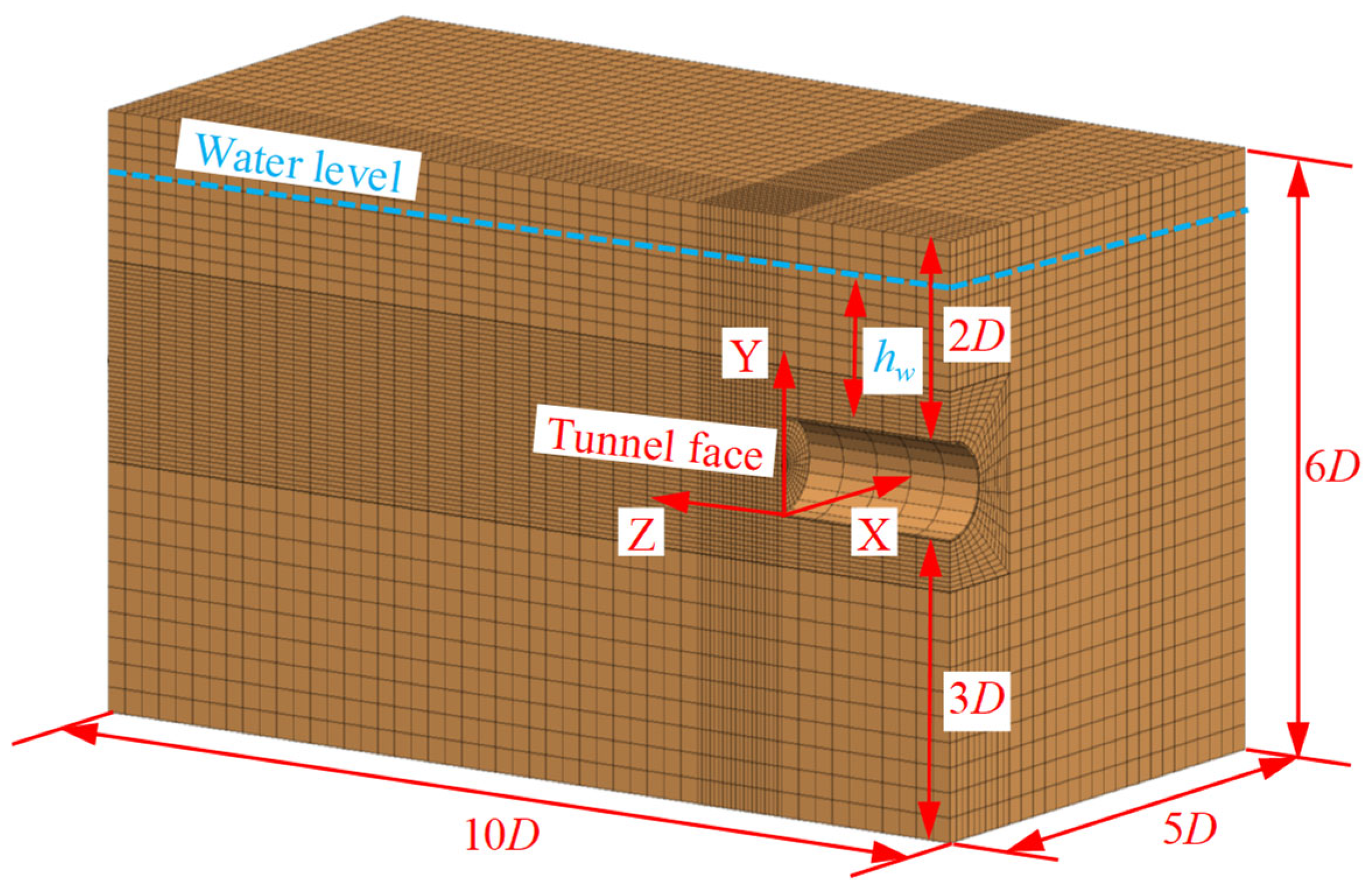
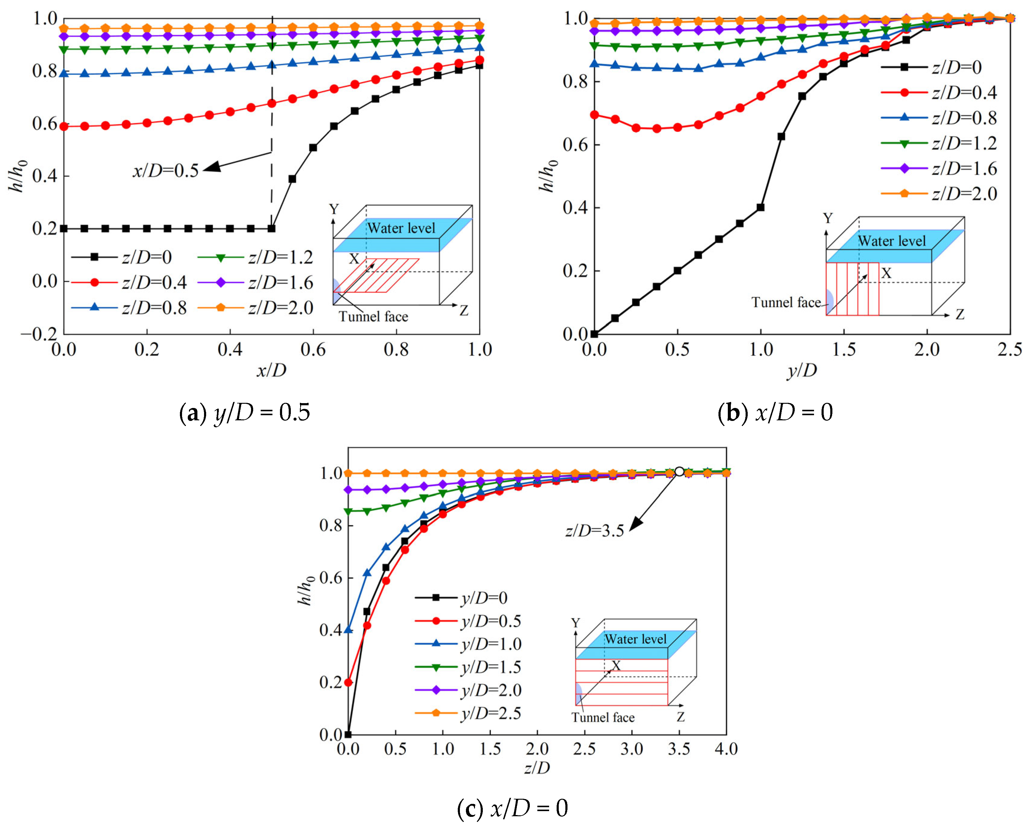
3.1. Numerical Model and Analysis of Calculation Results

Steady-state seepage analysis was conducted using finite difference software, as shown in Figure 2. Given the homogeneous formation and circular tunnel cross-section, the three-dimensional model is horizontally symmetrical, allowing for half-model calculations. To avoid boundary effects, the model’s range was set to 5D × 6D × 10D, with a tunnel excavation length of 2D, based on relevant studies [26,27,28]. As the water level increases, the burial depth in the model also increases accordingly to ensure it remains above the water level. The element size was approximately 2 m with a refined element size of about 0.5 m in the D-length area in front of the tunnel [22]. The formation’s permeability coefficient was 10−6 m/s. Boundary conditions were set as follows: the symmetrical plane and tunnel lining were impermeable, a constant water pressure was applied to the tunnel face, and the water pressure at the water level was kept constant. Figure 3 shows the contour plot of pore water pressure distribution in the surrounding rock near the shield tunnel face when hw = 15 m.
For ease of analysis, the normalized water head h/h0 is defined, and its variation near the tunnel face is plotted, as shown in Figure 4. The analysis shows that within the tunnel face range (x/D < 0.5), the water pressure variation along the tunnel cross-section direction (x-direction) is very small. Therefore, considering that the ultimate upper-bound failure mechanism only involves the front and upper local areas of the tunnel face, the variation in the x-direction can be neglected in subsequent water pressure distribution calculations. This reduces the Laplace governing equation from three dimensions to two dimensions. Further observation of the water pressure variations in the y (vertical) and z (tunnel axial) directions reveals that at 3.5D in the y-direction from the horizontal position and in the z-direction from the tunnel face, the water pressure has essentially returned to its initial state with minimal influence from seepage.

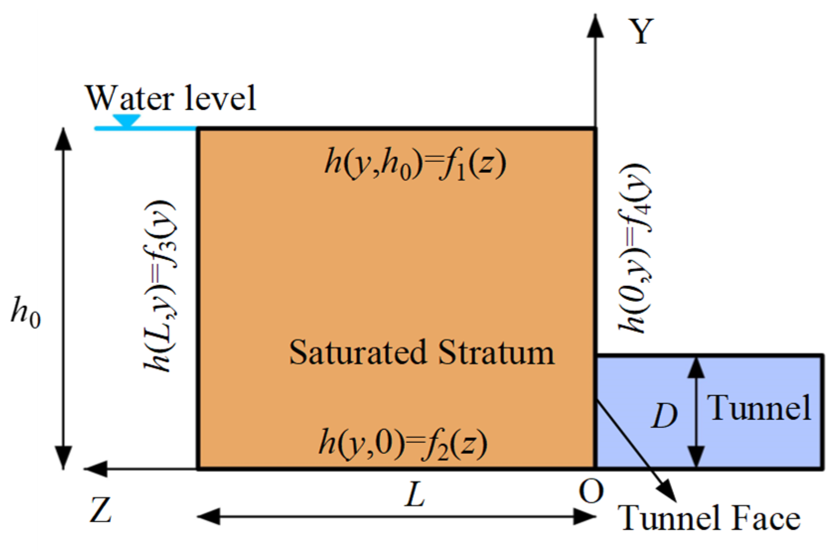
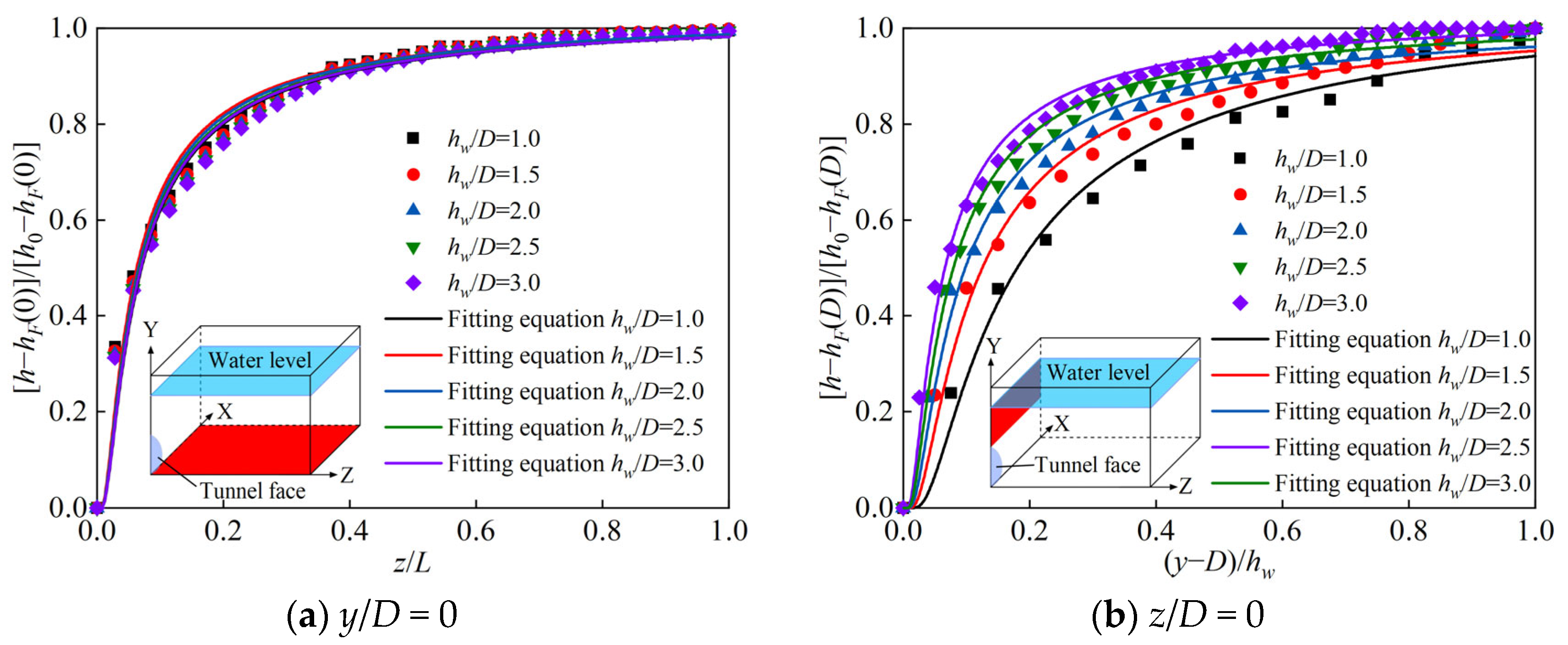
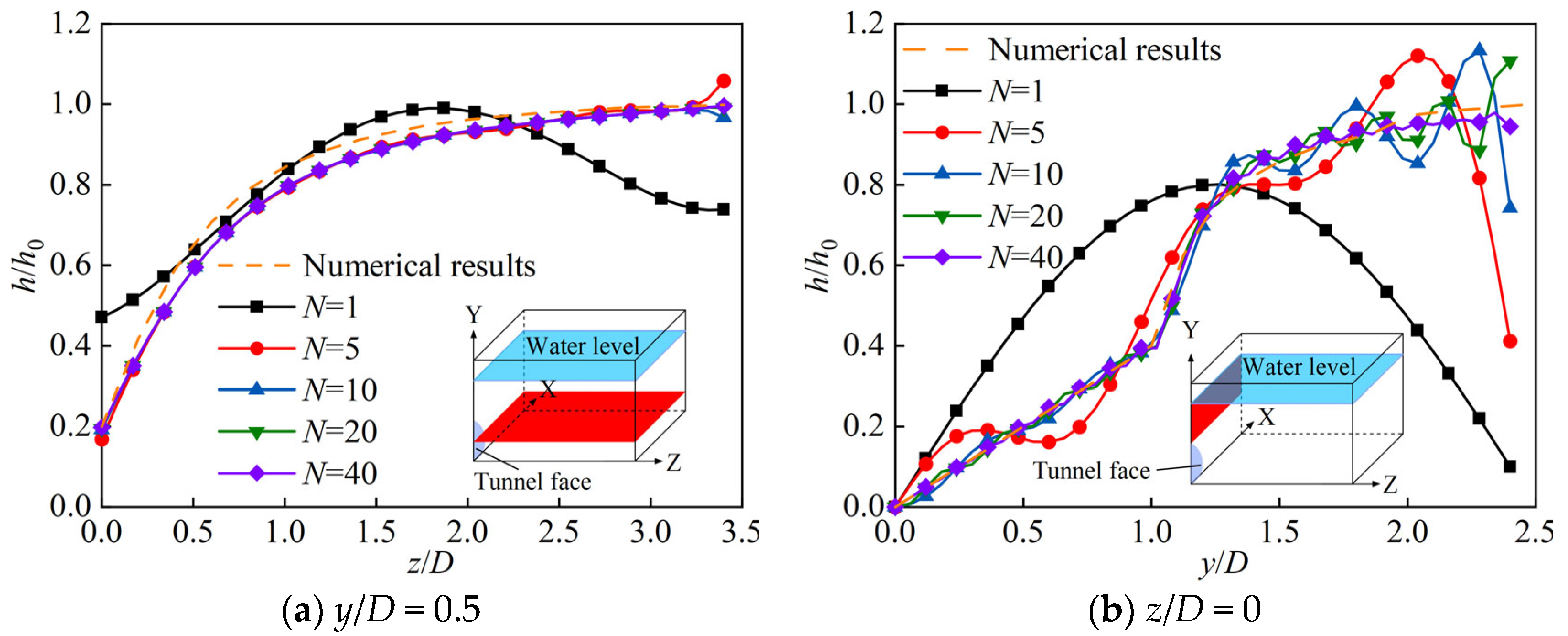
3.2. Theoretical Calculation Method for Seepage Field in Shield Tunnel Excavation

Based on the analysis in Section 3.1, the boundary conditions for steady-state seepage at the tunnel face can be simplified as shown in Figure 5. The longitudinal calculation range L can be taken as 3.5D.
Without considering the variation in water pressure in the x-direction and ignoring the impact of anisotropy in the permeability coefficient, the seepage field near the shield tunnel face satisfies the two-dimensional Laplace governing equation:
2 h z 2 + 2 h y 2 = 0
Assuming sufficient groundwater recharge, a stable groundwater level, and no seepage influence at a distance L in front of the tunnel, the boundary conditions can be expressed as
{ h ( z , h 0 ) = f 1 ( z ) = h 0 h ( z , 0 ) = f 2 ( z ) h ( L , y ) = f 3 ( y ) = h 0 h ( 0 , y ) = f 4 ( y )
The boundary conditions f2(z), f4(z) are fitted using numerical calculation results. According to the research by Perazzelli et al. [25], an exponential function can effectively fit the seepage field distribution in front of and above the tunnel face, as shown in Equation (6). The fitting results under the conditions of this engineering case are shown in Table 1 and Figure 6.
{ f 2 ( z ) = h F ( 0 ) + [ h 0 h F ( 0 ) ] · exp ( a L / z + b ) f 4 ( y ) = { h F ( y ) 0 y D h F ( D ) + [ h 0 h F ( D ) ] · exp [ c · h w / ( y D ) + d ] D < y < h 0
Thus, by solving the Laplace control equation (details in Appendix A), the water pressure at any point near the excavation face of the shield tunnel can be obtained:
h ( z , y ) = n = 1 K A , n sin ( λ n z ) sinh ( λ n y ) + n = 1 K B , n sin ( λ n · z ) sinh ( λ n · ( h 0 y ) ) + n = 1 K C , n sin ( L h w + D λ n y ) sinh ( L h 0 λ n z ) + n = 1 K D , n sin ( L h 0 λ n y ) sinh ( L h 0 λ n ( L z ) )
The coefficients KA,n, KB,n, KC,n and KD,n in the equation are calculated as follows:
{ K A , n = 2 L sinh ( h 0 λ ) 0 L f 1 ( z ) sin ( z λ ) d z K B , n = 2 L sinh ( h 0 λ ) 0 L f 2 ( z ) sin ( z λ ) d z K C , n = 2 h 0 sinh [ L 2 / ( h 0 λ ) ] 0 L f 3 ( y ) sin ( L λ y / h 0 ) d y K D , n = 2 h 0 sinh [ L 2 / ( h 0 λ ) ] 0 L f 4 ( y ) sin ( L λ y / h 0 ) d y
Equation (7) is an infinite series sum, but in practical calculations, the truncation term N must be considered. Figure 7 shows the calculation results for different truncation terms N. For non-boundary positions, when N = 1, the seepage head distribution curve deviates significantly; when N increases to 5, the curves are basically consistent. For boundary positions, the curve stabilizes only when N = 20; at N = 40, the curve is very stable. It is also observed that the curve corresponding to N = 40 from the analytical solution closely matches the curve obtained from numerical analysis. Therefore, in subsequent calculations, N = 40 can be used as the truncation term.
Based on the above analysis, the hydraulic head at any point can be calculated. To improve computational efficiency, a hydraulic head network with a spacing of 0.25 m is established within the potential failure mechanism range in front of the tunnel face. The hydraulic head at any point can be interpolated using the four vertices of the grid to which it belongs. The pore water pressure is given by
u i = γ w ( h i y )
where ui is the pore water pressure at a point in the stratum (kPa), hi is the total head at that point, and y is the position head, i.e., the distance from that point to the bottom of the tunnel.
Figure 8 shows the pore water pressure distribution obtained using the analytical method proposed in this paper.

4. Calculation of Ultimate Support Pressure for Shield Tunnel Face

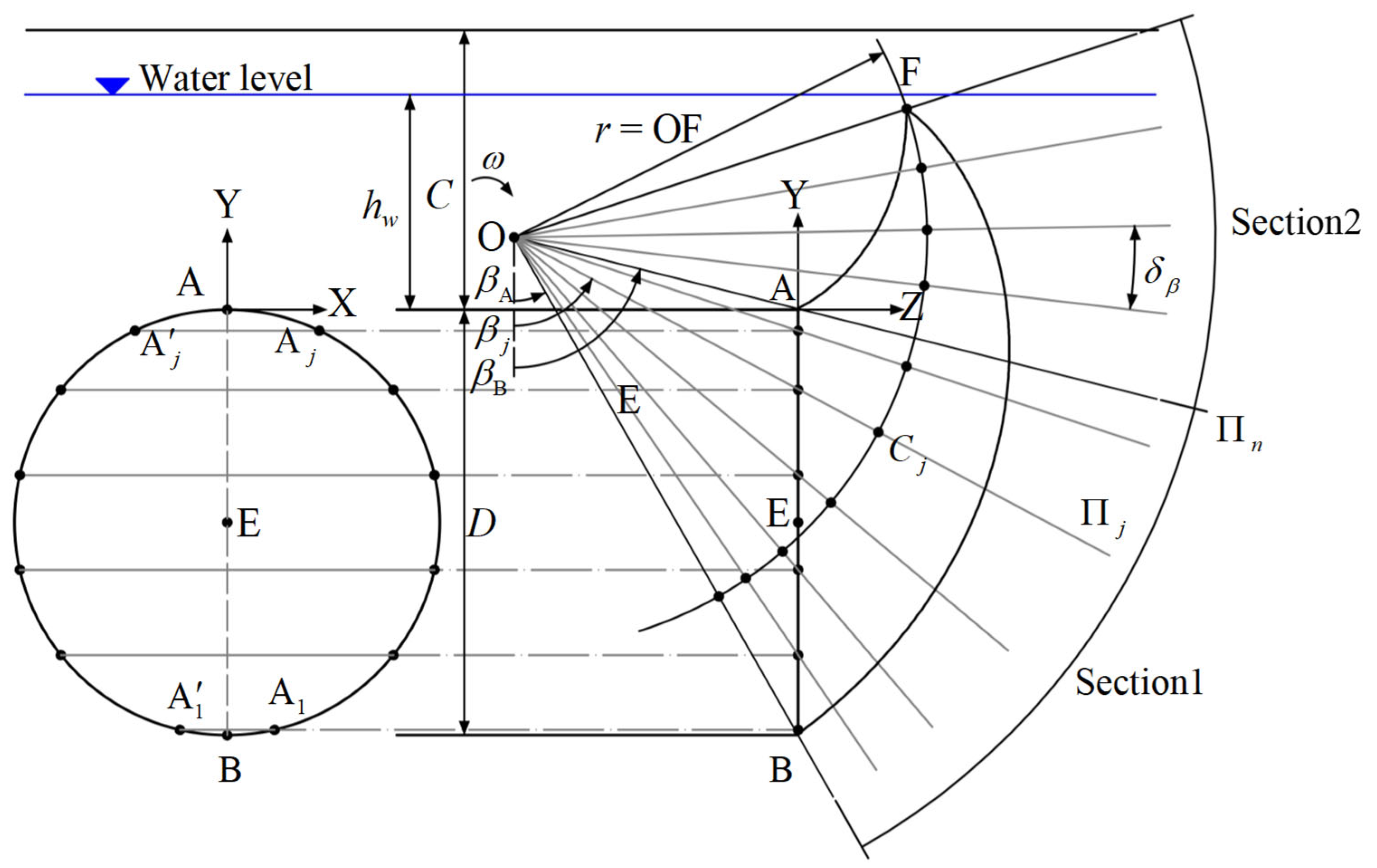
4.1. Establishment of the Three-Dimensional Failure Mechanism

The methods for calculating head and pore water pressure have been derived in previous sections. This section focuses on using spatial discretization techniques to derive the method for calculating the ultimate support pressure of the tunnel face based on the upper bound theorem of limit analysis. Figure 9 and Figure 10 illustrate the basic principles of spatial discretization. First, the tunnel face contour is discretized into 2n points, which are denoted as Aj (j = 1, 2…, 2n). These points define the radial rotation surfaces of region 1, which are denoted as Πj (j = 1, 2…, 2n). By rotating these surfaces counterclockwise by a fixed angle δβ, the radial rotation surfaces in region 2 are determined. From the 2n discrete points on the tunnel face contour, a series of points are generated on these radial rotation surfaces through the orthogonal theorem, ultimately forming a complete failure mechanism. The specific method can be referenced from the research by Mollon et al. [18].

4.2. Functional Equation

According to the upper bound theorem of limit analysis, the failure mechanism reaches a critical state when the external load power equals the internal energy dissipation power. At this point, the corresponding tunnel face support pressure is the ultimate support pressure. The external loads include gravity, seepage force, buoyancy, and tunnel face support pressure. The effects of seepage force and buoyancy can be transformed into the influence of pore water pressure on the failure mechanism. Therefore, the functional balance equation can be expressed as
E ˙ σ + E ˙ w + E ˙ γ = E ˙ e
where E ˙ σ, E ˙ w, E ˙ γ and E ˙ e represent the work power and energy dissipation power of the tunnel face support pressure, pore water pressure, soil gravity, and external loads, respectively. These can be calculated using Equation (12):
{ E ˙ σ = ω σ c j ( R j Σ j cos β j ) E ˙ γ = ω i , j ( γ sat R i , j V i , j sin β i , j ) E ˙ e = ω cos φ i j ( c R i , j S i , j ) E ˙ w = ω i j ( u i , j R j sin φ i , j S i , j ) + j ( u j R j Σ j cos β j )
where ω is the angular velocity of the mechanism rotating around point O, γsat and c denote the saturated unit weight and cohesion of the soil, Vi,j represents the volume of the prismatic discrete element in the local coordinate system (Figure 10b), Ri,j is the rotation radius of the prismatic element around point O, βi,j is the angle between the rotation radius and the negative Y-axis direction, Si,j and Σi,j, respectively, refer to triangular and rectangular discrete elements (Figure 10b), Rj and βj are the rotation radius and the angle between the rotation radius and the negative Y-axis direction for triangular and rectangular elements [15].
The ultimate support pressure of the tunnel face can be expressed as
σ t = ( E ˙ γ + E ˙ w E ˙ e ) / j ( Σ j R j cos β j )

5. Method Comparison Validation and Parameter Analysis

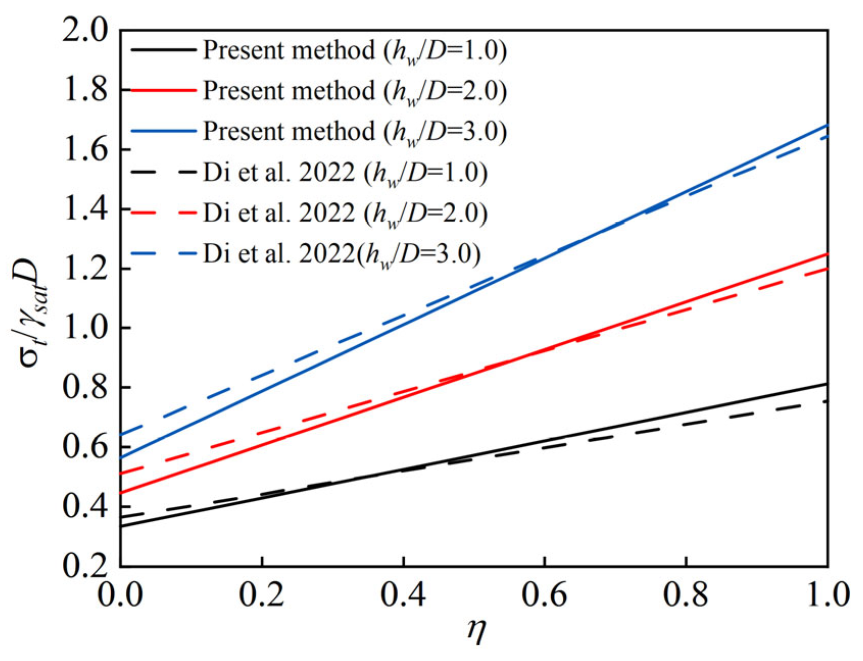
5.1. Method Comparison Validation
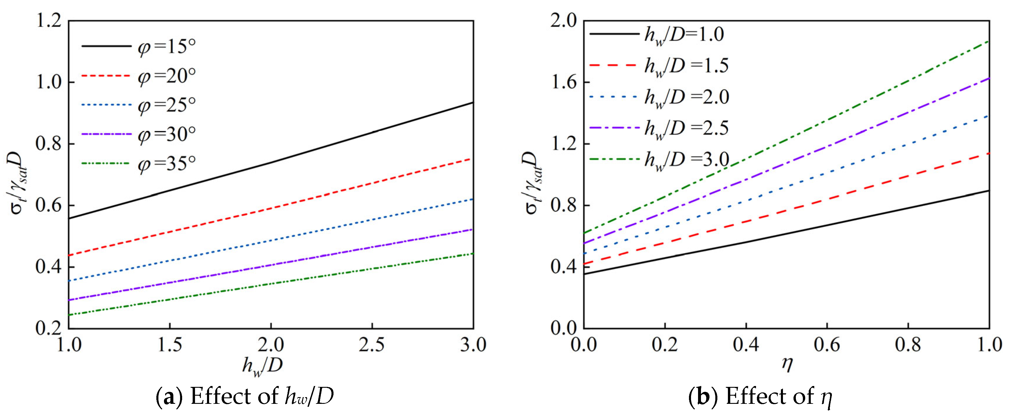
To verify the accuracy of the established calculation method, comparisons were made with the results of Di et al. [28], as shown in Figure 11. For ease of comparison, the normalized ultimate support pressure σtsatD was defined. It was observed that in terms of computational accuracy, when the tunnel face water pressure coefficient is small, the results in this study are slightly lower than those of Di et al. [28], whereas they are opposite when the water pressure coefficient is large. This discrepancy may be attributed to neglecting the variation in water head in the x-direction in this study. As x increases, the aquifer ahead of the tunnel face will recover the water head, increasing pore water pressure and resulting in higher calculated values. As η increases, the influence of seepage diminishes, reducing this gap over time.
In terms of computational efficiency, the two-dimensional analytical approach is more advantageous. Overall, the three-dimensional analytical water head equation is more accurate, while the two-dimensional analytical approach is more efficient.

5.2. Impact of Seepage on σtsatD

Seepage in the tunnel face is mainly influenced by water level and tunnel face water pressure. Therefore, these two parameters were selected for analysis with specific parameter settings as follows: c = 0 kPa, φ = 15~35°, D = 10 m, C = 30 m, γsat = 20 kN/m3, hw/D = 1~3, η = 0~1.
Figure 12a and Figure 12b, respectively, illustrate the variations of σt/γsatD with hw/D under different φ values and with η under different hw/D values. It can be observed that σt/γsatD shows a linear increase with increasing hw/D and η. As φ increases, the magnitude of σt/γsatD increase diminishes with increasing hw/D. Additionally, there is an interaction between hw/D and η, intensifying the increasing trend of σt/γsatD. This indicates that smaller φ values and larger hw/D and η lead to higher σt/γsatD.

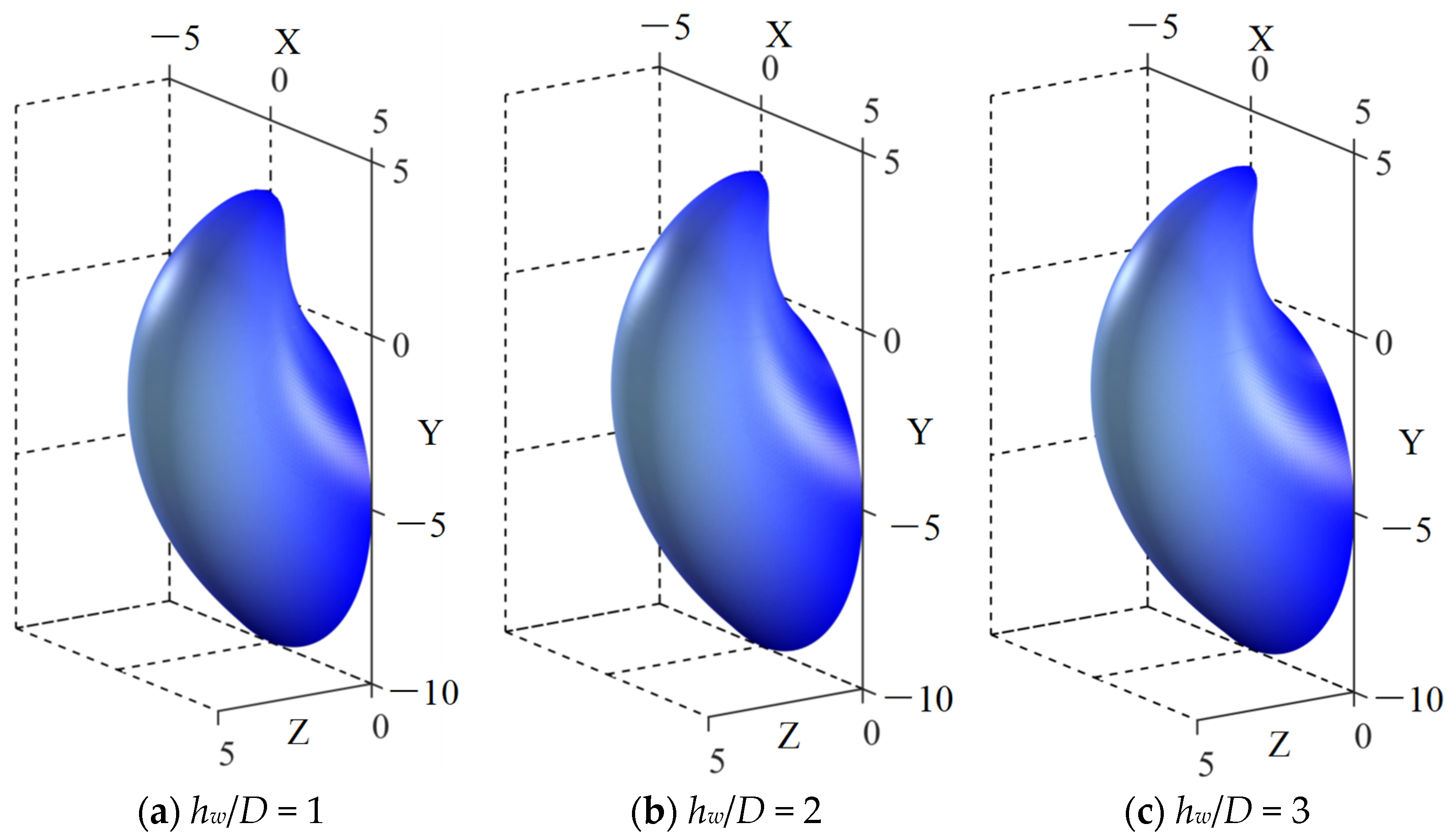
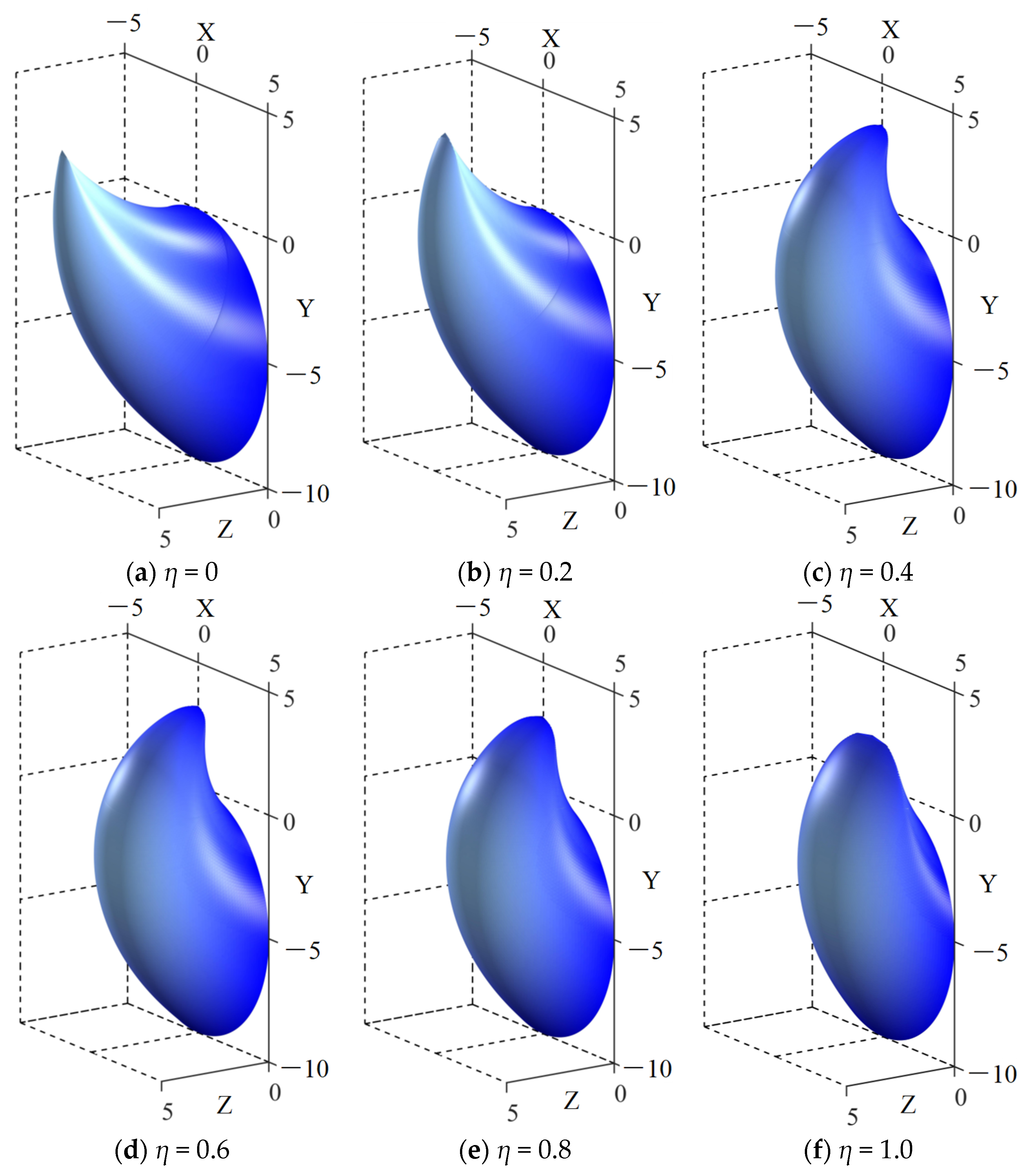
5.3. Impact of Seepage on Failure Mechanisms

Figure 13 and Figure 14 illustrate the failure mechanisms at the tunnel face under different conditions. For φ = 15°, c = 0 kPa, and D = 10 m, Figure 13 shows that as hw/D increases with η = 0.5, the failure mechanism gradually extends forward albeit with a small magnitude of change. In contrast, Figure 14 demonstrates variations in the failure mechanism at hw/D = 3 under different η values. As η decreases, the failure mechanism extends forward, whereas with increasing η, the volume of the failure mechanism gradually decreases. This indicates that changes in η have a significantly greater impact on the failure mechanism than changes in hw/D.

6. Calculation Method of Tunnel Face Support Pressure Based on Seepage Control

6.1. Determination of Target Water Pressure at Tunnel Face

According to Equation (3), the seepage at the tunnel face is primarily controlled by the water head, tunnel diameter, water pressure at the tunnel face, and permeability coefficient. Since changing the tunnel diameter during construction is difficult, there are mainly three methods to control seepage at the tunnel face. The first method is dewatering, but this approach may significantly disturb the surrounding hydrogeology and is generally not commonly used. The second method is to control the water pressure at the tunnel face. For earth pressure balance tunnel boring machines, besides maintaining the stability of the soil, seepage occurrence can also be limited by increasing the water pressure at the tunnel face, and setting the tunnel face support pressure is relatively straightforward. The third method involves techniques such as grouting to reduce the permeability of the strata ahead of the tunnel face, but grouting processes are complex and may affect construction efficiency. This paper mainly considers controlling seepage by increasing the water pressure at the tunnel face.
Taking hw = 15 m as an example, the influence of η on seepage at different permeability coefficients is analyzed, as detailed in Figure 15. Assuming 500 m3/d as the benchmark for controlling seepage, when the permeability coefficient is small (k ≤ 10−6 m/s), the water pressure at the tunnel face can be set to 0. However, when the permeability coefficient is large (k ≥ 10−4 m/s), the water pressure at the tunnel face needs to approach 1 to meet the seepage control requirements. Therefore, for different permeability coefficients of the strata, corresponding water pressure coefficients at the tunnel face need to be employed, which are expressed as follows:
η = 1 Q h w 3600 · π k D ( h 0 D / 2 ) 2
It is important to note that the seepage flow rate Q in Equation (3) is in units of m3/h. If the computed value of η is less than 0, it should be taken as 0. From Equation (13), it is evident that η is mainly influenced by Q, k, and hw.

6.2. Calculation Method

In existing research, the tunnel face water pressure is often set to zero, which is unreasonable for shield tunnel construction that requires seepage control [21,22,23,24,25]. To achieve seepage control, it is necessary to first calculate a reasonable tunnel face water pressure coefficient η. This coefficient is then used in seepage and limit analysis calculations to determine appropriate tunnel face support pressures, as depicted in Figure 16.
To demonstrate the impact of seepage control on σt, the calculation method proposed in this paper is utilized. Examples are computed for unit area seepage rates of 1.0, 1.5, and 2.0 m3/h/m2 at the tunnel face. Calculation parameters include c = 0 kPa, φ = 25°, D = 10 m, γsat = 20 kN/m3, and k = 5 × 10⁻⁵ m/s. After conversion, Q is obtained, and normalized tunnel face support pressures σt/γsatD are calculated for various ratios of water level to tunnel diameter (hw/D), as shown in Figure 17.
Observations indicate that when hw/D is small and the seepage control requirement is low, even with η = 0, the requirements can be met. In such cases, σt/γsatD increases slowly with hw/D. However, as η increases, σt/γsatD increases rapidly with hw/D. Neglecting seepage control by continuing to assume η = 0 in the calculation of σt/γsatD can lead to exceeding seepage limits and even accidents.

6.3. Comparison Considering Seepage Control

The impact of considering seepage control is demonstrated using a specific engineering project as an example, where calculations are compared based on whether seepage control is considered or not. This project traverses fine sand, medium sand, and coarse sand layers. For simplification, focus is placed on the cross-section passing through the coarse sand layer. The geological and construction parameters for this cross-section are c = 0 kPa, φ = 36°, D = 6 m, C/D = 2.8, γsat = 20.4 kN/m3, k = 80 m/d, and hw = 11.3 m. Calculations are compared using methods where the tunnel face support pressure is controlled based on seepage and where the tunnel face water pressure is assumed to be zero. The seepage-controlled method employs a standard of 2.0 m3/h/m2 for unit area seepage. Results are presented in Table 2 where the safety factor is defined as the ratio of the actual support pressure used to the calculated support pressure. It is observed that significant differences in calculated outcomes arise based on whether seepage control is considered or not. In this project, a support pressure of 209 kPa was utilized, ensuring smooth progress in excavation. Had seepage control been considered, the safety factor would have been 1.4, whereas assuming zero water pressure at the tunnel face would have necessitated a safety factor of 5.4. Considering typical safety factors employed in engineering design underscores the necessity of designing tunnel face support pressures based on seepage control.

7. Conclusions

During tunnel excavation, excessive seepage can significantly impact construction safety. Increasing the tunnel face support pressure to raise the excavation face water pressure and reduce seepage flow is essential. This paper presents a method for calculating the tunnel face’s ultimate support pressure based on seepage control. By introducing a two-dimensional water head distribution formula and a three-dimensional failure mechanism, a stability analysis model for tunnel faces under steady-state seepage conditions in saturated strata is established. The influence of seepage parameters on the ultimate support pressure is analyzed, and the variation in seepage flow under different permeability coefficients and tunnel face water pressure coefficients is explored. Furthermore, a method for calculating the tunnel face support pressure based on seepage control is proposed.
(1)
Based on the two-dimensional Laplace control equation combined with the seepage numerical analysis model, the water head calculation formula under steady-state seepage conditions in saturated soil is derived. This formula is incorporated into the three-dimensional limit analysis model. The calculation results are consistent with existing research, verifying the reliability of the analysis model.
(2)
The ultimate support pressure σt increases linearly with the water level and the tunnel face water pressure coefficient η. The interaction between the water level and η exacerbates the increase in σt. As the water level and η increase, the three-dimensional failure mechanism transitions from an extended forward shape to a more contracted form with a reduction in volume. The influence of η on the failure mechanism shape is significantly greater than that of the water level.
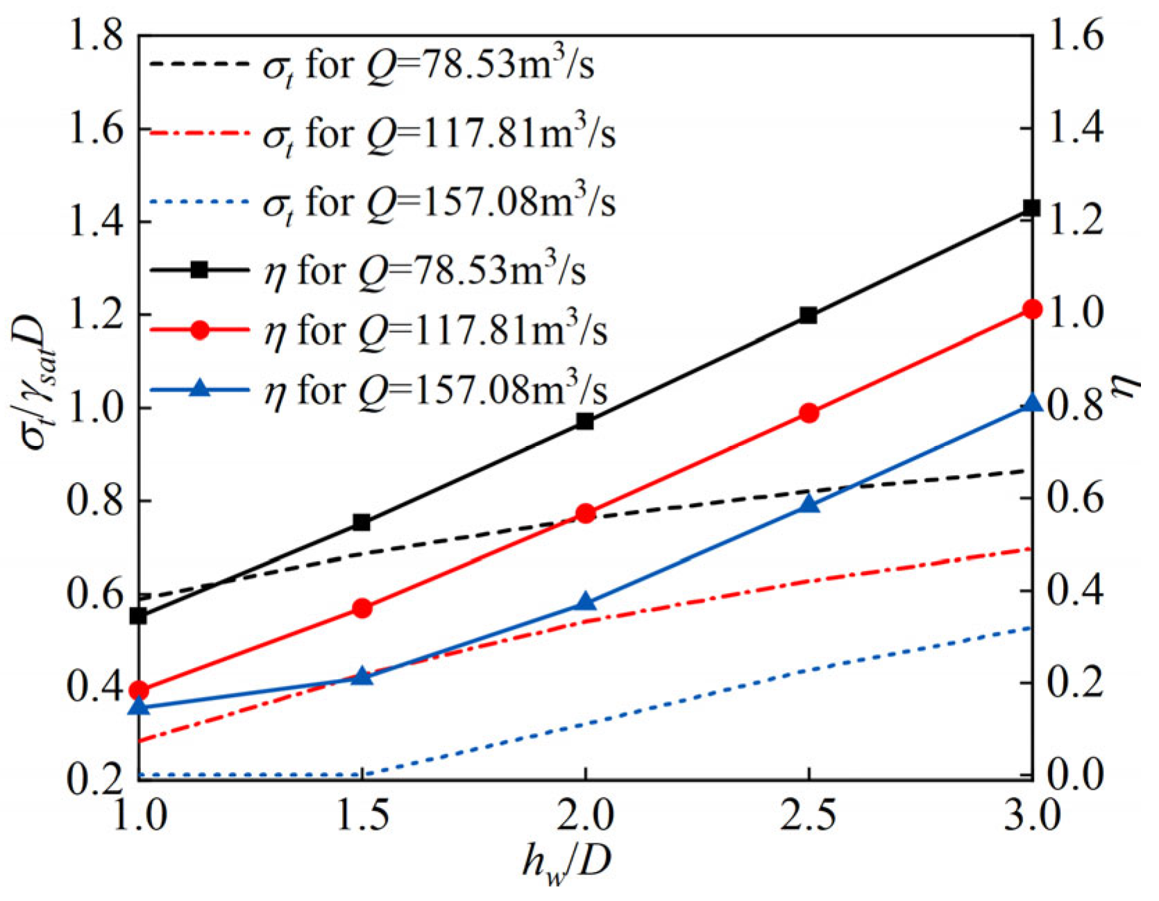
(3)
The tunnel face water pressure coefficient η is mainly influenced by the seepage flow at the tunnel face, the permeability coefficient of the stratum, and the water level. These three parameters can be used to calculate the appropriate η. Based on this, a method for calculating the ultimate support pressure of the shield tunnel faces considering seepage control is proposed. Comparative studies with other methods in practical engineering projects demonstrate the superiority of this method and the necessity of considering seepage control. This method allows for a more reasonable calculation of the tunnel face water pressure and support pressure.

8. Discussion

This study is limited to homogeneous single-layer strata. In practice, many engineering projects involve multiple layers, where differences in permeability coefficients, cohesion, friction angles, and other parameters exist between layers. Additionally, even within a single layer, parameters exhibit natural spatial variability. Future research could explore multi-layered strata and consider the spatial variability of layer parameters.

Author Contributions

Z.H.: Formal analysis, Software, Writing—original draft. M.L.: Conceptualization, Methodology, Validation, Supervision. H.Z.: Supervision, Writing—review and editing, Data Curation. C.J.: Writing—review and editing, Formal analysis. C.S.: Data curation, Conceptualization. All authors have read and agreed to the published version of the manuscript.

Funding

This research was funded by the National Natural Science Foundation of China (grant no. 52378420, 52008403), the Fundamental Research Funds for the Central Universities (grant no. 502802002), and the Natural Science Foundation of Hunan Province (grant no. 2024JJ9080).

Institutional Review Board Statement

Not applicable.

Informed Consent Statement

Not applicable.

Data Availability Statement

The original contributions presented in the study are included in the article; further inquiries can be directed to the corresponding author.

Conflicts of Interest

The authors declare no conflicts of interest.

Abbreviations

The following symbols are used in this paper:
C, DBuried depth and tunnel diameter
hw, h0Water level measured from the top and bottom of the tunnel
hF,AWater head at the center of the tunnel face
kPermeability coefficient
ηWater head coefficient at the tunnel face
a, b, c, dSeepage boundary function fitting parameters
NTruncation term in seepage calculation
uiPore water pressure at any point
E ˙ σ E ˙ γ, E ˙ e, E ˙ wPower of support pressure, weight of soil, cohesion, and pore water pressure
Vi,jVolume of the triangular element
Si,j, Σi,jArea of triangular and quadrilateral elements
βi,j, Ri,jDiscrete element’s rotation angle and radius
σtLimit support pressure
AjDiscrete points on the tunnel face
CjThe geometric center of radial planes
c, φEffective cohesion and internal friction angle
ωAngular velocity of the failure mechanism rotating about point O
Pi,jDiscrete points on the failure mechanism

Appendix A

This appendix aims to demonstrate the solution process of the two-dimensional Laplace governing equation discussed in Section 3.2. The two-dimensional Laplace governing equation is
2 h y 2 + 2 h z 2 = 0
Based on the linear nature of the governing equation and boundary conditions, its analytical solution can be decomposed into four parts according to the boundary conditions, namely
h ( z , y ) = h 1 ( z , y ) + h 2 ( z , y ) + h 3 ( z , y ) + h 4 ( z , y )
Each equation, while satisfying the two-dimensional Laplace equation, meets the following boundary conditions, respectively:
{ h 1 ( z , h 0 ) = f 1 ( z ) h 1 ( z , 0 ) = 0 h 1 ( L , y ) = 0 h 1 ( 0 , y ) = 0
{ h 2 ( z , h 0 ) = 0 h 2 ( z , 0 ) = f 2 ( z ) h 2 ( L , y ) = 0 h 2 ( 0 , y ) = 0
{ h 3 ( z , h 0 ) = 0 h 3 ( z , 0 ) = 0 h 3 ( L , y ) = f 3 ( y ) h 3 ( 0 , y ) = 0
{ h 4 ( z , h 0 ) = 0 h 4 ( z , 0 ) = 0 h 4 ( L , y ) = 0 h 4 ( 0 , y ) = f 4 ( y )
For the four equations, the method of separation of variables can be used to solve them. This paper demonstrates the solution process using h1(z,y) as an example. First, h1(z,y) is decomposed into univariate functions of y and z:
h 1 ( z , y ) = Z ( z ) · Y ( y )
Substituting Equation (A7) into the Laplace equation of Equation (A1), we obtain
Z ( z ) · Y ( y ) + Y ( y ) · Z ( z ) = 0
Let Z″(z)/Z(z) and −Y″(y)/Y(y) be constants (denoted as λ). Thus, we obtain two ordinary differential equations:
{ Z ( z ) λ Z ( z ) = 0 Y ( y ) + λ Y ( y ) = 0
Given that Z(0) = Z(L) = Y(0) = 0, the general solution can only be
{ Z ( z ) = A cos ( λ y ) + B sin ( λ y ) Y ( y ) = C exp ( λ z ) + D exp ( λ z )
Substituting the boundary conditions Z(0) = Z(L) = 0 gives A = 0, thus
Z ( z ) = B sin ( λ z ) = 0
Substituting the boundary condition Y(0) = 0 gives C = −D, thus
Y ( y ) = C ( e λ y e λ y ) = C sinh ( λ y )
To ensure the existence of a non-trivial solution, let B ≠ 0; then, we have:
λ L = n π ( n = 1 , 2 , 3 , )
Thus
λ = ( n π / L ) 2
Substituting the boundary condition h1(z,h0) = f1(z) and using Fourier series expansion, we obtain
K A , n = B D = 2 L sinh ( h 0 λ ) 0 L f 1 ( z ) sin ( z λ ) d z
Thus, we obtain h1(z,y)
h 1 ( z , y ) = n = 1 K A , n sin ( λ n · z ) sinh ( λ n · y )
Similarly, we can obtain
{ h 2 ( z , y ) = n = 1 K B , n sin ( λ n z ) · sinh [ λ n ( h 0 y ) ] h 3 ( z , y ) = n = 1 K C , n sin [ L h 0 λ n y ] · sinh [ L h 0 λ n z ] h 4 ( z , y ) = n = 1 K D , n sin [ L h 0 λ n y ] · sinh [ L h 0 λ n ( L z ) ]
where
{ K B , n = 2 L sinh [ h 0 λ ] 0 L f 2 ( z ) sin ( z λ ) d z K C , n = 2 h 0 sinh [ L 2 / h 0 λ ] 0 L f 3 ( y ) sin ( L λ y / h 0 ) d y K D , n = 2 h 0 sinh ( [ L 2 / h 0 λ ] ) 0 L f 4 ( y ) sin ( L λ y / h 0 ) d y

References

  1. Lei, M.; Shi, Y.; Tang, Q.; Sun, N.; Tang, Z.; Gong, C. Construction control technology of a four-hole shield tunnel passing through pile foundations of an existing bridge: A case study. J. Cent South Univ. 2023, 30, 2360–2373. [Google Scholar] [CrossRef]
  2. Liu, J.; Shi, C.; Gong, C.; Lei, M.; Wang, Z.; Peng, Z.; Cao, C. Investigation of ultimate bearing capacity of shield tunnel based on concrete damage model. Tunn. Undergr. Space Technol. 2022, 125, 104510. [Google Scholar] [CrossRef]
  3. Lei, M.; Liu, L.; Shi, C.; Tan, Y.; Lin, Y.; Wang, W. A novel tunnel-lining crack recognition system based on digital image technology. Tunn. Undergr. Space Technol. 2021, 108, 103724. [Google Scholar] [CrossRef]
  4. Lei, M.; Peng, L.; Shi, C. An experimental study on durability of shield segments under load and chloride environment coupling effect. Tunn. Undergr. Space Technol. 2014, 42, 15–24. [Google Scholar] [CrossRef]
  5. Zhao, C.; Lei, M.; Shi, C.; Cao, H.; Yang, W.; Deng, E. Function mechanism and analytical method of a double layer pre-support system for tunnel underneath passing a large-scale underground pipe gallery in water-rich sandy strata: A case study. Tunn. Undergr. Space Technol. 2021, 115, 104041. [Google Scholar] [CrossRef]
  6. Zou, J.; Qian, Z.; Xiang, X.; Chen, G.H. Face stability of a tunnel excavated in saturated nonhomogeneous soils. Tunn. Undergr. Space Technol. 2019, 83, 1–17. [Google Scholar] [CrossRef]
  7. Li, W.; Zhang, C. Face Stability Analysis for a Shield Tunnel in Anisotropic Sands. Int. J. Geomech. 2020, 20, 04020043. [Google Scholar] [CrossRef]
  8. Shi, Z.; Xu, J.; Xie, X.; Li, P.; Chai, L.; Li, S. Failure mechanism analysis for tunnel construction crossing the water-rich dense fracture zones: A case study. Eng. Fail. Anal. 2023, 149, 107242. [Google Scholar] [CrossRef]
  9. Zhang, X.; Wang, M.; Lyu, C.; Tong, J.; Yu, L.; Liu, D. Experimental and numerical study on tunnel faces reinforced by horizontal bolts in sandy ground. Tunn. Undergr. Space Technol. 2022, 123, 104412. [Google Scholar] [CrossRef]
  10. Lü, X.; Zhao, Y.; Xue, D.; Lim, K.; Qin, H. Numerical modelling of shield tunnel face failure through a critical state sand plasticity model with nonlocal regularization. Comput Geotech. 2023, 164, 105847. [Google Scholar] [CrossRef]
  11. Di, Q.; Li, P.; Zhang, M.; Cui, X. Experimental study of face stability for shield tunnels in sandy cobble strata of different densities. Tunn. Undergr. Space Technol. 2023, 135, 105029. [Google Scholar] [CrossRef]
  12. Liu, C.; Zhang, S.; Zhang, D.; Zhang, K.; Wang, Z. Model tests on progressive collapse mechanism of a shallow subway tunnel in soft upper and hard lower composite strata. Tunn. Undergr. Space Technol. 2023, 131, 104824. [Google Scholar] [CrossRef]
  13. Senent, S.; Jimenez, R. A tunnel face failure mechanism for layered ground, considering the possibility of partial collapse. Tunn. Undergr. Space Technol. 2015, 47, 182–192. [Google Scholar] [CrossRef]
  14. Mollon, G.; Dias, D.; Soubra, A. Probabilistic Analysis of Pressurized Tunnels against Face Stability Using Collocation-Based Stochastic Response Surface Method. J. Geotech. Geoenviron. 2011, 137, 385–397. [Google Scholar] [CrossRef]
  15. Subrin, D.; Wong, H. Stabilité du front d’un tunnel en milieu frottant: Un nouveau mécanisme de rupture 3D. Comptes Rendus. Mecanique. 2002, 330, 513–519. [Google Scholar] [CrossRef]
  16. Chen, W.F.; Scawthorn, C.R. Limit analysis and limit equilibrium solutions in soil mechanics. Soils Found. 1970, 10, 13–49. [Google Scholar] [CrossRef] [PubMed]
  17. Mollon, G.; Dias, D.; Soubra, A. Face Stability Analysis of Circular Tunnels Driven by a Pressurized Shield. J. Geotech. Geoenviron. 2010, 136, 215–229. [Google Scholar] [CrossRef]
  18. Mollon, G.; Dias, D.; Soubra, A. Rotational failure mechanisms for the face stability analysis of tunnels driven by a pressurized shield. Int. J. Numer. Anal. Met. 2011, 35, 1363–1388. [Google Scholar] [CrossRef]
  19. Zhang, D.; Jiang, J.; Zhang, J. The Stability of Upper Bound Analysis of Soft Rock Tunnel Faces Under Different Underground Water Levels. Geotech. Geol. Eng. 2021, 39, 4393–4404. [Google Scholar] [CrossRef]
  20. Yin, X.; Chen, R.; Meng, F. Influence of seepage and tunnel face opening on face support pressure of EPB shield. Comput. Geotech. 2021, 135, 104198. [Google Scholar] [CrossRef]
  21. Pan, Q.; Dias, D. The effect of pore water pressure on tunnel face stability. Int. J. Numer. Anal. Met. 2016, 40, 2123–2136. [Google Scholar] [CrossRef]
  22. Hou, C.; Pan, Q.; Xu, T.; Huang, F.; Yang, X. Three-dimensional tunnel face stability considering slurry pressure transfer mechanisms. Tunn. Undergr. Space Technol. 2022, 125, 104524. [Google Scholar] [CrossRef]
  23. Liu, J.; Liu, L. Stability of Tunnel Face Reinforced by Bolts under Seepage Flow Conditions. KSCE J. Civ. Eng. 2022, 26, 977–986. [Google Scholar] [CrossRef]
  24. Anagnostou, G. The influence of tunnel excavation on the hydraulic head. Int. J. Numer. Anal. Met. 1995, 19, 725–746. [Google Scholar] [CrossRef]
  25. Perazzelli, P.; Leone, T.; Anagnostou, G. Tunnel face stability under seepage flow conditions. Tunn. Undergr. Space Technol. 2014, 43, 459–469. [Google Scholar] [CrossRef]
  26. Li, W.; Zhang, C.; Tan, Z.; Ma, M. Effect of the seepage flow on the face stability of a shield tunnel. Tunn. Undergr. Space Technol. 2021, 112, 103900. [Google Scholar] [CrossRef]
  27. Di, Q.; Li, P.; Zhang, M.; Guo, C.; Wang, F.; Wu, J. Three-dimensional theoretical analysis of seepage field in front of shield tunnel face. Undergr. Space 2022, 7, 528–542. [Google Scholar] [CrossRef]
  28. Di, Q.; Li, P.; Zhang, M.; Zhang, W.; Wang, X. Analysis of face stability for tunnels under seepage flow in the saturated ground. Ocean Eng. 2022, 266, 112674. [Google Scholar] [CrossRef]
  29. Di, Q.; Li, P.; Zhang, M.; Jia, Y.; Li, S.; Cui, X. Experimental study on the effect of seepage flow on the tunnel face stability in the saturated ground. Ocean Eng. 2024, 299, 117074. [Google Scholar] [CrossRef]
  30. Di, Q.; Li, P.; Zhang, M.; Wu, J. Influence of permeability anisotropy of seepage flow on the tunnel face stability. Undergr. Space 2023, 8, 1–14. [Google Scholar] [CrossRef]
  31. Bear, J. Hydraulics of Groundwater; Mc Graw-Hill: New York, NY, USA, 1979. [Google Scholar]
  32. Zhang, Y. Study on the Hydraulic Flow Regime Characteristics in Subsea Tunnels and Its Engineering Application. Ph.D. Thesis, Beijing Jiaotong University, Beijing, China, 2021; pp. 56–61. (In Chinese). [Google Scholar]
Figure 1. Diagram of seepage at the tunnel face.
Applsci 14 06781 g001
Figure 2. Numerical model for seepage analysis in shield tunnel excavation.
Applsci 14 06781 g002
Figure 3. Contour plot of pore water pressure distribution induced by shield tunnel excavation.
Applsci 14 06781 g003
Figure 4. Numerical calculation results of water pressure distribution near the tunnel face.
Applsci 14 06781 g004
Figure 5. Boundary conditions for the steady-state seepage problem at the tunnel face.
Applsci 14 06781 g005
Figure 6. Fitting results of the boundary conditions.
Applsci 14 06781 g006
Figure 7. Impact of truncation number N on water head distribution in analytical methods and comparison with numerical analysis.
Applsci 14 06781 g007
Figure 8. Pore water pressure distribution calculated by the analytical method.
Applsci 14 06781 g008
Figure 9. Sketch of the cross-section and longitudinal section of the discrete failure mechanism.
Applsci 14 06781 g009
Figure 10. Generation of failure mechanism using spatial discretization technique.
Applsci 14 06781 g010
Figure 11. Comparison with other studies [28].
Applsci 14 06781 g011
Figure 12. Effect of seepage-related parameters on normalized ultimate support pressure.
Applsci 14 06781 g012
Figure 13. Failure mechanism shapes under different hw/D (unit: m).
Applsci 14 06781 g013
Figure 14. Failure mechanism shapes under different η (unit: m).
Applsci 14 06781 g014
Figure 15. Relationship between η and Q under different k.
Applsci 14 06781 g015
Figure 16. Flowchart for calculating the ultimate support pressure of tunnel face based on seepage control.
Applsci 14 06781 g016
Figure 17. Relationship between σt/γsatD and hw/D under different Q.
Applsci 14 06781 g017
Table 1. Parameter fitting results.
hw/DabR2 (f2)cdR2 (f4)
1.0−0.04540.03150.982−0.13920.07930.983
1.5−0.04780.03500.981−0.09220.04400.985
2.0−0.04920.03180.980−0.07100.03170.987
2.5−0.05030.03250.979−0.05760.03430.987
3.0−0.05110.03300.979−0.04800.03760.988
Table 2. Comparison of calculation results.
Support Pressure/kPaSafety Factor
The actual support pressure used209-
Considering seepage control149.8 (η = 0.96)1.4
Not considering seepage control38.8 (η = 0)5.4
Disclaimer/Publisher’s Note: The statements, opinions and data contained in all publications are solely those of the individual author(s) and contributor(s) and not of MDPI and/or the editor(s). MDPI and/or the editor(s) disclaim responsibility for any injury to people or property resulting from any ideas, methods, instructions or products referred to in the content.

