Article

Numerical Simulation Study of Cavity Formation in Soil under Blast Load

1
Faculty of Mining Geology and Petroleum Engineering, University of Zagreb, Pierottijeva 6, 10000 Zagreb, Croatia
2
Faculty of Geotechnical Engineering, University of Zagreb, Hallerova aleja 7, 42000 Varaždin, Croatia
*
Author to whom correspondence should be addressed.
Appl. Sci. 2024, 14(15), 6790; https://doi.org/10.3390/app14156790 (registering DOI)
Submission received: 9 June 2024 / Revised: 15 July 2024 / Accepted: 1 August 2024 / Published: 3 August 2024
(This article belongs to the Section Civil Engineering)

Abstract

:
The main applications of civil explosives in soils are soil compaction, mass excavation, and in situ pile creation. The suitability of explosives for each of these applications strongly depends upon the explosive properties and the soil properties. For those reasons, a reliable estimation or process simulation regarding cost efficiency and explosive work ability in the soil with known soil parameters is relevant. This paper presents a numerical simulation study of different types of soil (different amounts of gravel, sand, silt, and clay) under a blast load modeled using Ansys 2020 R1 Autodyn 2D hydrocode, with different types of explosives. The calculated results from the Ansys 2020 R1 Autodyn 2D and the experimental results obtained from the in situ cavity formation caused by blasting are presented. The Jones–Wilkins–Lee (JWL) equation of state parameters was calculated using EXPLO5 V7.01.01 supported by experimental data, while the soil and explosive properties were measured in laboratory and in situ.

1. Introduction

Since soil is a heterogeneous medium, and civil explosives such as ANFO or powdered ammonium nitrate explosives are characterized with a non-ideal detonation behavior, the aim of this study is to find a reliable numerical model that can predict soil behavior under a blast load. In order to predict soil deformation under an impact load, such as one that is produced by an explosion, it is important to identify the deformation mechanisms that can occur in high-strain conditions.
The common practice in modeling soil behavior under a blast load is primarily based on empirical formulas from field tests [1].
For the last two decades, many researchers have been studying numerical simulation under a blast load, and numerical models were derived and validated on explosives with ideal detonation behavior, such as TNT or C4. Also, they have used sand (saturated or unsaturated) as the media [1,2,3,4,5]. Some correlations are established between the spherical cavity volume and the blasting charge mass and type of explosive used, as well as its detonation and blasting parameters [6].
However, there are a huge number of different soils in nature, with corresponding deformation mechanisms. This diversity has produced a great number of theories with different initial models of soil. Also, the theoretical problem that occurs is based on the fact that an explosion in a solid medium is a dynamic process [7].
According to the classification, soil can be cohesive or non-cohesive. In cohesive soils, two deformation mechanisms exist. In the first deformation mechanism at low pressure, the soil skeleton deformation is determined by the elastic deformation of bonds on the contact surfaces of grains; the first mechanism at high pressure is determined by a failure in bonding and the displacement of grains (plastic deformation). The second deformation mechanism is the deformation of all the soil phases. When soil is being compressed, both mechanisms act simultaneously, but at certain phases of the loading, one of the mechanisms predominates [7].
In terms of explosive performance in soil, the first stage is the impact effect. In that phase, pressed gasses act like a rigid barrier that hits the soil, and compaction occurs. In the next stage, expanded gasses can migrate in the soil layer next to the border with a cavity. That kind of process can occur when the action of several nearby blast holes or a free face exists in the charge vicinity zone. In the case of a buried charge when a cavity is produced, generally, gasses cannot migrate in the compacted soil, because the soil is compacted, densified, and acts like a barrier to the gasses in expansion. First, the impact effect on the explosion tends to make natural air and water migrate from the explosion zone. That process causes soil to be densified to values near crystal density because all-natural air and water do not exist in that zone anymore, and the soil particles are arranged and pressed.
Different types of explosives are used in blasting practice. Also, they generally have different values of detonation parameters depending on the performance and workability under different conditions and surroundings.
There are several methods to predict the workability of explosives in different materials and intendent functionality, such as lead block test, ballistic mortar, underwater explosion test, cylinder test, Hess test, Kast test, plate dent test, etc. [8]. One of the predictor methods that can be used is the TNT equivalent method. In that approach, the explosive of interest is compared with TNT in a manner of theoretic heat, pressure, velocity of detonation (VOD). The problem with that approach is that explosives with different explosion processes are compared. TNT is an ideal explosive that detonates in the most ideal manner. On the other hand, for the in-cylinder expansion test, which was used in the detonation model applied in Ansys 2020 R1 Autodyn 2D, experimental constants and real exact values of detonation parameters are crucial.
Civil explosives that are used for blasting have non-ideal detonation, which is characterized by different, mostly lower values of energy, pressure, velocity of detonation, and a longer duration of the heat liberation process [9,10,11]. On the other hand, that duration and afterburning process (after detonation sonic point) liberate additional energy, especially in contained conditions. Small, concentrated charges cannot be approached in a regular, ideal detonation model view, but must be well modeled with experimentally approved data. By using an experimentally validated model, reliable parameters of cavity dimensions and densification can be predicted.

2. Materials and Methods

In the present research, the first step was to collect real parameters of soil properties that appear in nature. The parameters of civil explosives that are common in engineering practice, such as ANFO, ammonium nitrate powder explosive, and water gel, were also determined.
The values of the soil parameters for density, grain size distribution, plasticity limits, and moisture content, used in the numerical simulation study were previously tested in a geotechnical laboratory. The results of the soil parameters are presented in Table 1.
From the values of the soil parameters presented in Table 1, it can be noticed that the studied materials cover the range from low-to high-plasticity soils with a plasticity index from 7 to 29%.
An important input parameter for numerical simulation is the dependence of soil density under different loads, and that parameter is determined in laboratory conditions. The dependance of soil volume under different loads is graphically presented in Figure 1.
The velocities of detonation (VOD) of the concerned explosive properties were derived from experimental results, measured by the electro-optical method, with the same properties and confiment at the test field in charges as in simulations. The VOD values have been measured according to the relevant European standards and presented in Table 2. Given that civil explosives based on ammonium nitrate (AN) exhibit a certain degree of non-ideality, their detonation properties depend on the explosive charge diameter and the existence and/or properties of the charge confinement. Considering that, some part of the explosive mass remains unreacted in the moment at the beginning of the expansion (i.e., the reactions continue during the expansion), the detonation properties of these explosives cannot be accurately predicted by the Chapman-Jouguet detonation theory. To account for non-ideal behavior, the so-called “partial equilibrium” detonation model, incorporated in EXPLO5 V7.01.01, is used in this study. The model is invoked in EXPLO5 V7.01.01 by specifying the amount of initial AN that is assumed to react until the C-J point. The actual amount of reacted AN was determined by an iterative procedure, in such a way that the amount of reacted AN is changed until the calculated detonation velocity was equal to the experimental one. Experimental VOD values, densities and chemical composition, were used as input data for the EXPLO5 V7.01.01 thermochemical code, i.e., its non-ideal detonation model.
The expansion isentrope is calculated by the aforementioned partial equilibrium detonation model, assuming chemical equilibrium between the detonation products until a freeze-out temperature (which is set to be 2100 K). Based on the calculated p-V data along the expansion isentrope, the JWL coefficients are derived using the non-linear fitting sub-routine incorporated in EXPLO5 V7.01.01 code [12].
The chemical composition of the studied explosives is as follows:
-
Pakaex: NH4NO3 and mineral oil; ANFO
Permonex: ammonium nitrate, trinitrotoluene, dinitrotoulene, paraffin wax, and moisture; Ammonium nitrate powder explosive
-
Riogel (: NH4NO3, MMAN, water, NaNO3, and aluminum. Watergel

3. Numerical Simulation Results and Discussion

The numerical simulation was performed using Ansys 2020 R1 Autodyn 2D hydrocode via a Compaction EOS Linear model. It is a relevant model since it is based on pressure and density dependence, and it has been proven by experimental data.
Also, the model is described in the Euler system (2D) with fixed boundaries that ensure the continuity of the material and prevent the reflection of the stress wave at the boundaries.
For a Compaction EOS linear model, the response of materials is represented through a plastic compaction path defined as a piecewise linear function of pressure versus density, and the elastic unloading/reloading path is defined via a piecewise function of sound speed versus density. Both, the compaction and unloading/reloading paths are indicated by tabular data of compaction pressure versus density and tabular data of sound speed against density.
A fixed compaction path derived from static compression data was applied. This ignores the pressure enhancement due to the energy absorption. The elastic bulk stiffness of the material is defined as a piecewise linear curve of sound speed (c) versus density (ρ0) and is given by following equation:
K = ρ0 c2
The level of compaction in the material is given by following equation:
α = ρs/ρ0
Initially, ρ0 will be equal to the value defined in the density property of the material. Material property ρs is the solid zero pressure density of the material and corresponds to the fully compacted material density. For a porous material, the initial density will be less than the solid density; hence, the value of α will be greater than 1.0. As compaction takes place, α will reduce to a value of 1.0 for the fully compacted state [13].
The isentropic expansion of the detonation products was modeled by using the Jones–Wilkins–Lee (JWL) equation of state (EOS) given by the following equation [14]:
P = A 1 ω R 1 V e R 1 V + B 1 ω R 2 V e R 2 V + ω E V
where P is the pressure; A, B, R1, R2, and ω are the constants; V is the specific volume of detonation product over the specific volume of undetonated explosive; and E is the specific (volume) theoretical detonation energy.
The JWL (Jones–Wilkins–Lee) constants for the ANFO explosive are determined using thermochemical EXPLO5 V7.01.01 [13], applying the partial equilibrium detonation model, and they are given in Table 3. It should be noted that, according to the model, the JWL constants change as the VOD changes. Thus, for example, the constants will have different values for the same explosive at different charge diameters, which is related to the non-ideal behavior.

3.1. Validation of Numerical Model

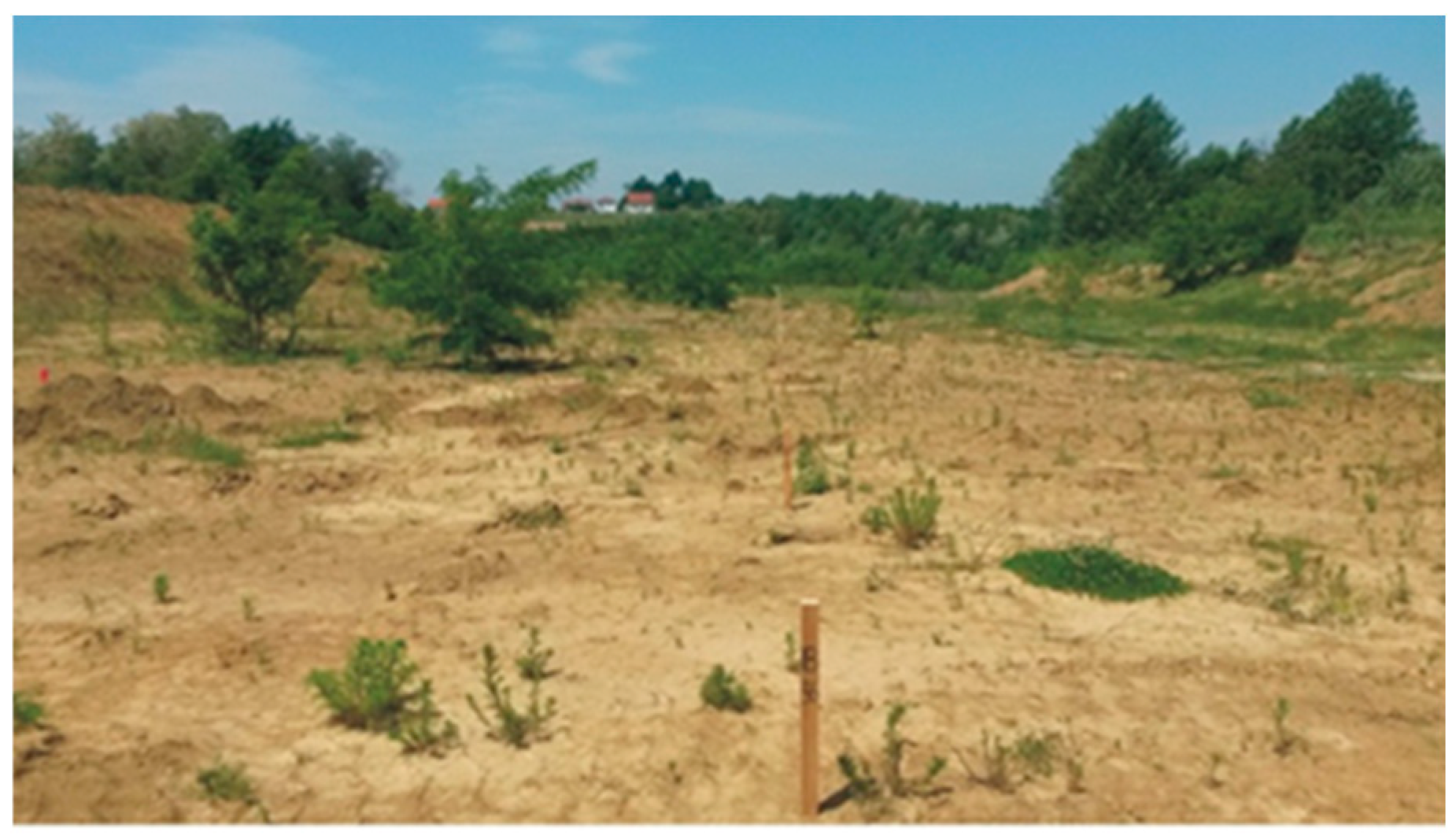
The validation of a numerical model plays an important role in a numerical simulation study. In this research, the validation was performed using experimental values of cavity volumes. The used experimental results are derived from recent research in order to determine the interaction between explosives and soil properties. Those research were performed in situ in natural soil. The cavity formation in soil were produced by blasting on a test field, and ANFO and powdered AN explosives were used. Figure 2 shows the test field.
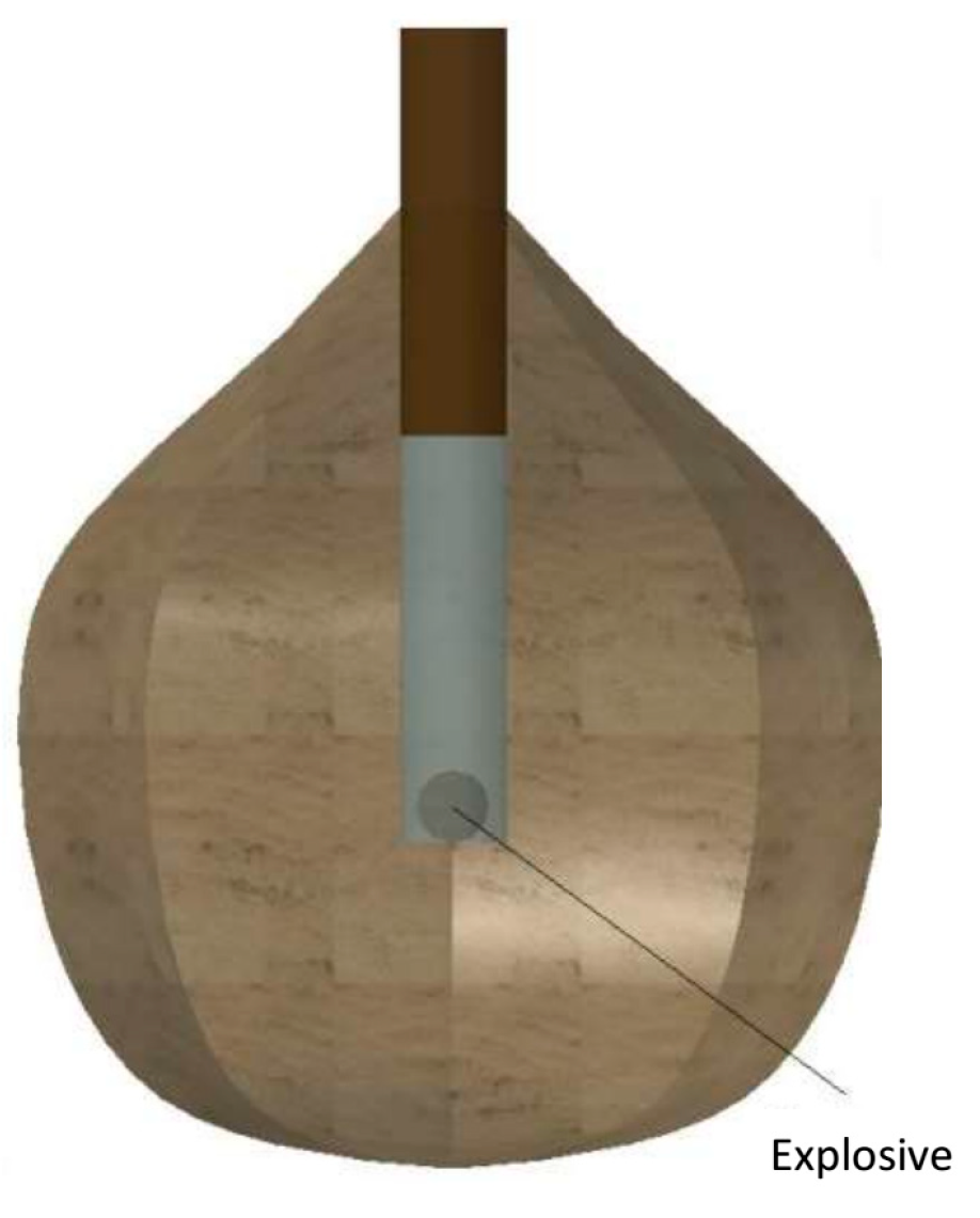
The results of cavity volume obtained from field experiments are compared with the cavity volume calculated by a numerical model. That procedure was carried out prior to the modeling aimed at model-validation. The measurements of the cavity volume were carried out using a system with a camera and laser. The results were processed using AutoCad Civil 3D software [15,16]. An example of the processed, measured cavity in graphical form is shown in Figure 3.
As mentioned in Section 2, the properties of the blasted soil were determined and entered in a numerical model.
In a borehole of 131 mm diameter and 2440 mm depth, 1 kg of a Pakaex (ANFO) explosive was placed and initiated with a plain detonator, and in a second borehole, the same procedure was repeated with a different explosive, Permonex (powdered ammonium nitrate explosive). The stem was made of sand material with a length of 0.5 m. The main results of the explosions were cavities with a volume of 752 dm3 for ANFO [15,16] and 835 dm3 for the powdered explosive.
The validation results of the numerical model (measured and calculated by Ansys 2020 R1 Autodyn 2D) are presented in Table 4.
The results of the validation allow for the conclusion that the numerical model describes the soil response under the load caused by blasting within an acceptable range. The deviation between the measured and modeled values is between 6 and 12% and is acceptable, as the model is strongly dependent on the input data. Input experimental data are subjected to errors connected with the imperfection of the cavity volume measurement method and the real values of explosive parameters.

3.2. Results of Numerical Simulation

The simulation setups were basically the same for the different explosives, with a difference in the charge length, which is related to the explosive density used. The lengths were 6 cm for Riogel, 7 cm for Permonex, and 10 cm for Pakaex. The Euler 2D model was applied in a block with the dimensions 300 (j-axis) × 400 (i-axis) cm. The cell dimensions were 1 × 1 cm, ensuring the same number of cells as the path dimensions. The total number of cells was 120,000. The flow out was encompassed with boundaries in both directions. The stem was represented by sand material with a length of 50 cm. The part dimensions were chosen in a way to assure there was no influence of the blast on the soil material in the distance and reflection at the boundary was prevented. On the other hand, part dimension and the number of cells were chosen so as not to affect the speed of the calculation.
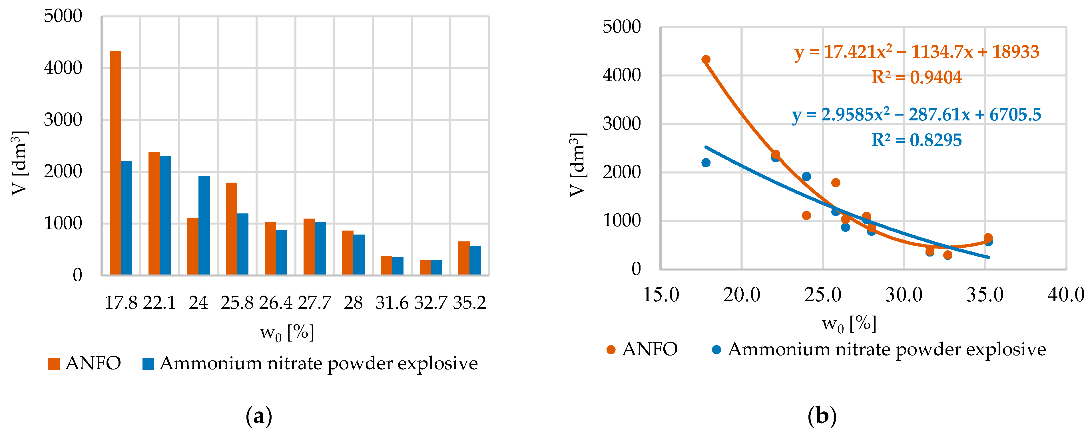
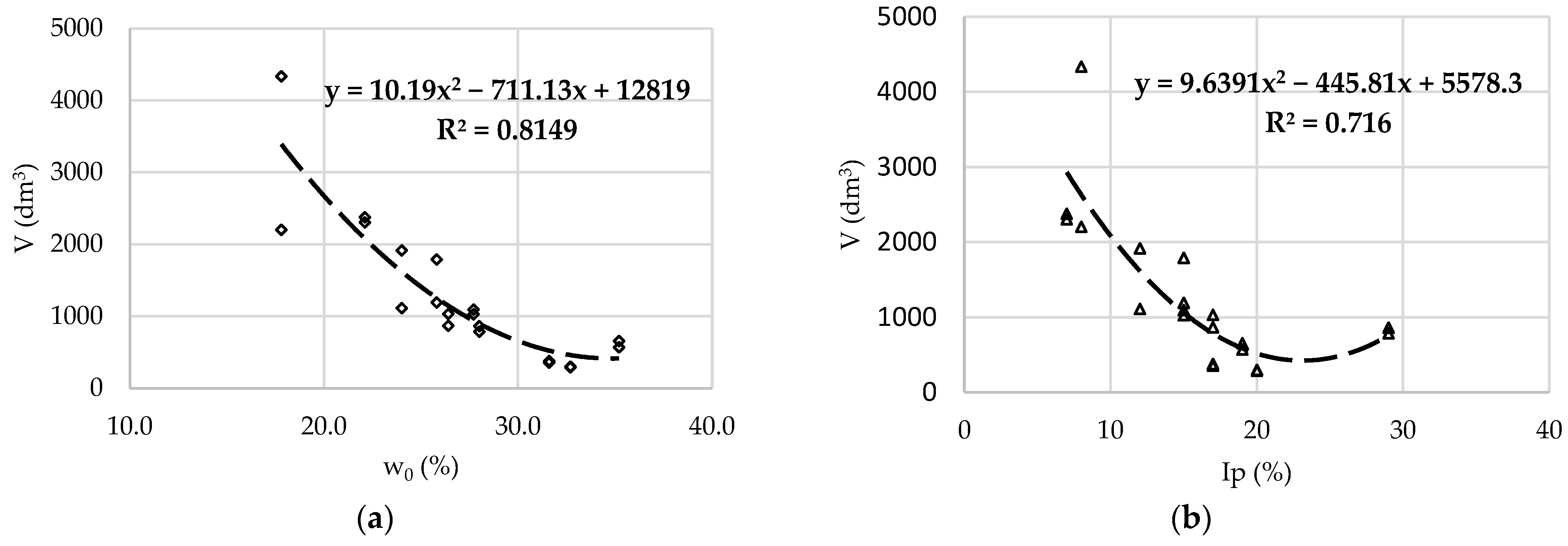
The process causes soil to be densified to values near crystal density because all-natural air and water were pressed from that zone and soil particles are arranged and pressed, which is proven in the simulation and field measurements. In a practical manner, the zone with an increased density is the active load zone for the installed anchors. The results of the numerical simulation are presented in Table 5, and the relation of cavity volume with water content for the specific explosives is shown in Figure 4.
According to the correlation results, it can be concluded that water content can be a reliable predictor when speaking of cavity formations caused by blasting, and that is not a surprising result. Although a very simple geotehnical parameter, water content plays an important role when dealing with soil problems.
The amount of water, disposition of water in soil and disposition of the pressures in water, has a huge influence on the soil behavior in terms of loading [17].
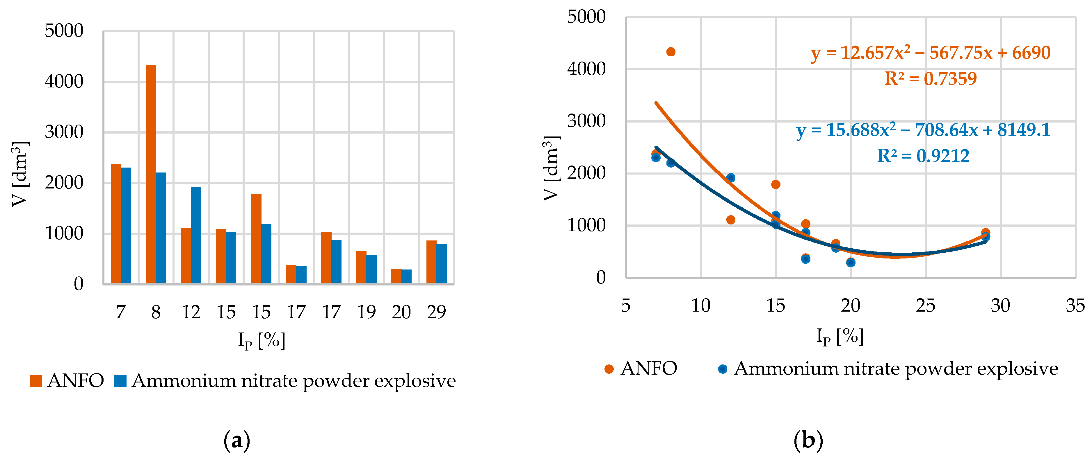
The relation of cavity volume with plasticity index for the specific explosives is shown in Figure 5.
According to the analysis and results displayed in Figure 5, the plasticity index can also be a reliable predictor for the volume of cavity formation.
A difference between the volume of the cavity produced by ANFO and also produced by powdered ammonium nitrate explosive is noticed in the case of soil sample S-8. It is a low-plasticity soil with lower water content (17.8%) and a significant amount of sand (17.9%). According to the results, it can be noticed that in soils with a smaller amount of water, with respect to the plasticity index, the ANFO explosive generally produces a bigger cavity than the powdered explosive. The reason may lie in the fact that ANFO explosive produces a slightly bigger volume of gas products (nearly 10%), but for further explanation, it is important to provide more experiments and simulations for soils with similar parameters.
It can be generally stated that soils from different locations have similar plasticity index results and the liquid limit has very similar properties, such as stiffness and shear strength [17]. In that manner, the plasticity index can also be a reliable predictor for volume of cavity in soil caused by blasting.
The results of statistical analyses showed a good agreement between volume of cavity and basic geotechnical parameters: water content (w0) and plasticity index (IP).
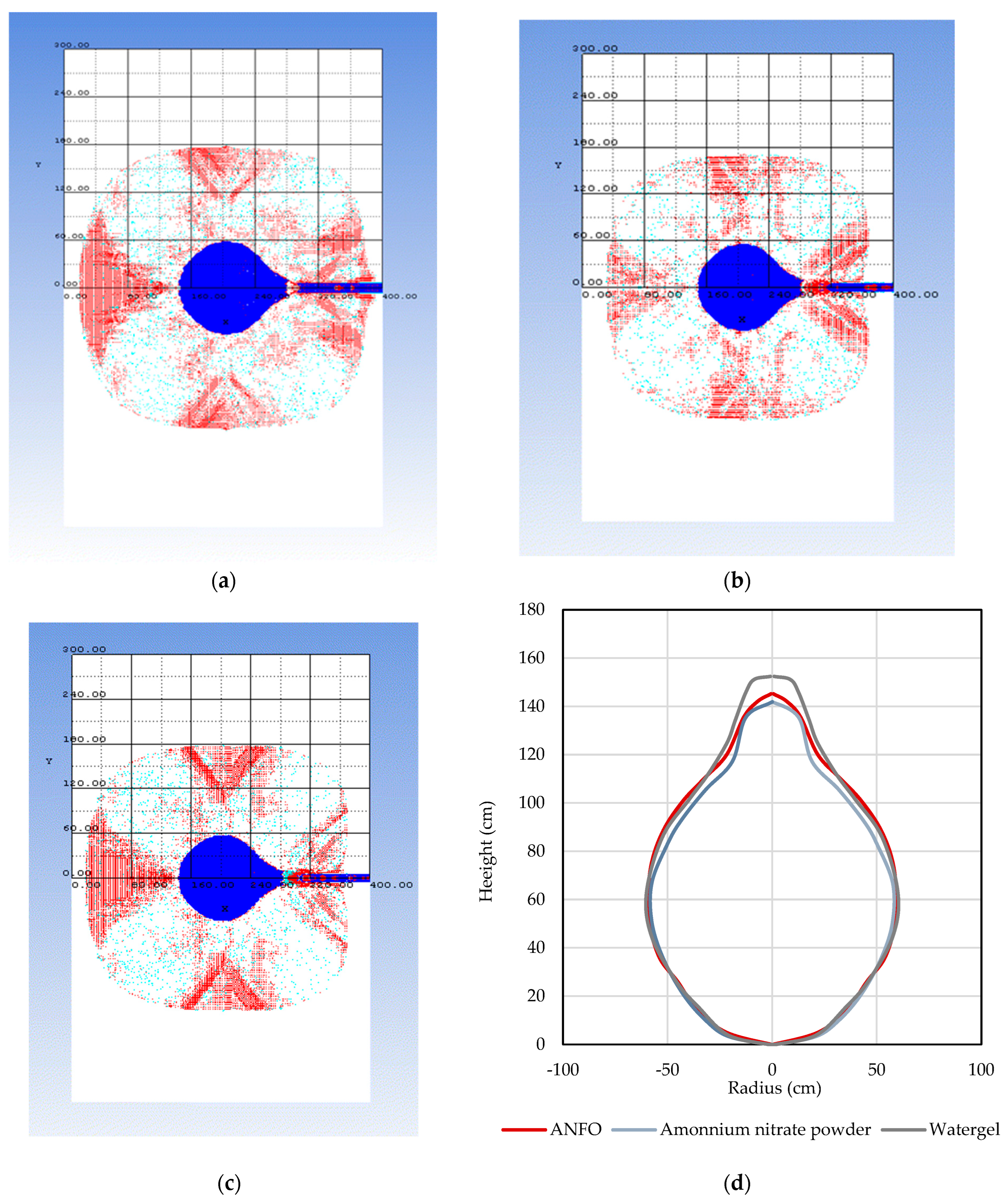
A simulation was also performed on the water gel explosive for the S-1 type of soil. The results showed a similar cavity formation for all three types of non-ideal explosives (ANFO, ammonium nitrate, and water gel explosive). The results are presented in Table 6 and in Figure 6. The dimensions of the cavity shown in Figure 6 were determined by digitalization using the open-source Engauge Digitizer Software [18].
The studied non-ideal explosives with different theoretical and experimental parameters showed a similar volume of cavity value with a similar charge mass. It can be concluded that in conditions of soil, the charge mass is crucial, opposite to detonation velocity (VOD) or detonation (borehole) pressure and detonation energy or specific volume of gasses. On the other hand, some dissipation of volume results exist in the range of circa 10%. This indicates that dissipation can be assigned to the measurement uncertainty of the experimental volume measurement method and the non-ideality of the applied explosive. Since the mechanical strengths of soils are significantly lower than the stresses produced by the pressures of the expansion gasses applied by explosives, the differences in cavity volume for the concerned explosives’ mass are not influenced by the level of the VOD or the applied pressure of those explosives, and the differences in volume are minor. After equilibrium is reached in the surrounding soil, the remaining energy is used to elongate the stem area. So, according to the simulation and performed test, the main parameters that influence the cavity volume are charge mass, soil moisture content, and plasticity. The shape of the cavity depends on the charge position, or elongation of the a priori borehole, and corresponds well with the direction of the detonation wave propagation related to the charge axle. In that manner, the elongated shape of the cavity is related to the detonation pressure, and the total cavity volume is related to the charge mass and total liberated energy. The experimental results show that the difference in the volume of the cavity produced by the ANFO and the powdered explosive is not significantly different and differs in the order of 10% (752 and 835 dm3) from the observed cavities with the same charge mass of 1.0 kg. It can also be seen that the type of explosive has an influence on the shape of the cavity, with the ANFO explosive producing a larger diameter cavity and the AN powder explosive producing a relatively larger deepening. This may be related to the difference between the impact component and the expansion component of the work ability of the explosive, i.e., the higher pressure of the powdered AN explosive compared to the ANFO. With ANFO explosives, the delayed reactions behind the sonic point still release energy and affect the expansion before venting the gasses through the stem zone. The total cavity volume for equal masses of the applied explosive type does not differ significantly. For non-ideal explosives, it can be concluded that the most important parameter is the mass of the explosive, while the detonation pressure, detonation velocity, and gas volume are less important.
The simulations performed for the situations covered by the experiment showed similar dependencies, that is, the type of explosive slightly influences observable changes in the cavity volume.
By introducing water gel into the simulation along with the aforementioned ANFO and AN powder explosive, cavity sizes within 10% were confirmed for all of the observed explosives. By analyzing the size of the parameter “Power of explosives”, i.e., the product of the theoretical heat of detonation and the volume of released gasses that are the carriers of the performed work, it can be confirmed that the results of the simulations and the experimental values coincide with the increase in the product QV for individual explosives. The major dissipation is with the ANFO. The properties of ANFO explosives are highly non-ideal and depend on the environmental conditions, the confinement, the shape of the charge and the type and method of initiation. The use of models describing non-ideal explosives with ideal properties is possible but is subject to corrections based on experimentally determined values of individual properties, especially detonation velocity. The detonation velocity used in the calculations was reduced to 2000 m/s, which corresponds to the measured value of a charge of 100 mm height and 131 mm diameter initiated in a borehole under experimentally simulated conditions. In contrast, the theoretical, calculated detonation velocities for ANFO explosives are given in the literature, with values for the maximum theoretical detonation velocity up to 5000 m/s and up to 3500 m/s for charges with a diameter of 60 to 80, for example. Similarly, the detonation velocity of the AN powder explosive was adjusted from 5500 m/s to 4000 m/s based on the measurement results, corresponding to the measured values in the actual charge.
The correlations that are shown in Figure 7 confirm that for cavity formation, the Ansys 2020 R1 Autodyn 2D hydro code with the Compaction EOS Linear model can predict the volume of a cavity within an error limit of 12%. Also, reliable experimental data of moisture content and plasticity index can predict the volume of a cavity when using the following equations:
V = 10.19w02 − 711.13w0 + 12,819
V = 9.6391 I P 2 445.81 I P + 5578.3
Finally, it is important to mention that when explosives act in the soil, because of the process’ attributes, densification in the surrounding soil and penetration of gasses in soil pores [19,20,21] are always present. However, this research was only focused on the prediction of cavity volume formation.

4. Conclusions

The effect of non-ideal explosives in the soils was researched by simulation with the Ansys 2020 R1 Autodyn 2D computer program, and the results of the simulations were compared with the results of test blasts. In order to research the influence of the mechanical soil parameters, simulations were carried out for ten soil types. As input parameters for the soil properties, data from laboratory tests in an oedometer were used, which provided the necessary data for the linear model of the load on the observed soils.
According to the performed research, it can be concluded that the volume of the cavity in the soil depends on the mass of the explosive, or in other words, the volume of the cavity increases with the mass of the charge, which corresponds to the amount of energy released.
The volume of the cavity increases with decreasing relative humidity and a lower plasticity index.
From this, it can be concluded that the application of the model integrated in Ansys 2020 R1 Autodyn 2D is possible, but with a considerable correction of the ideal explosive parameters and the JWL parameters. This correction is possible by combining the values obtained by applying a computer code in the EXPLO5 V7.01.01 program, which takes into account the non-ideality of the explosives used. These values are determined on the basis of the experimentally measured detonation velocities.
The applicability of the research presented lies in the planning and design of blasting work in soils. Using known parameters, such as water content and plasticity index, for the soil and detonation velocity for the explosive, the volume of the cavity can be calculated. In this way, the modeled volume can be used for geotechnical design without test blasts with acceptable uncertainty.

Author Contributions

Conceptualization, M.D. and I.D.; methodology, M.D.; software, M.S. and M.D.; validation, M.D., I.D. and D.T.; formal analysis, M.D.; investigation, M.D.; resources, D.T. and I.D.; writing—original draft preparation, M.D. and I.D.; writing—review and editing, M.D. and I.D. All authors have read and agreed to the published version of the manuscript.

Funding

This research received no external funding.

Institutional Review Board Statement

Not applicable.

Informed Consent Statement

Not applicable.

Data Availability Statement

Data and information developed in this research are available by emailing the authors upon any reasonable request.

Conflicts of Interest

The authors declare no conflicts of interest.

References

  1. Wang, Z.; Hao, H.; Lu, Y. A three-phase soil model for simulating stress wave propagation due to blast loading. Int. J. Numer. Anal. Methods Geomech. 2004, 28, 33–56. [Google Scholar] [CrossRef]
  2. Wang, Z.; Lu, Y. Numerical analysis on dynamic deformation mechanism of soil under blast loading. Soil Dyn. Earthq. Eng. 2003, 23, 705–714. [Google Scholar] [CrossRef]
  3. An, J.; Tuan, C.Y.; Cheeseman, B.A.; Gazonas, G.A. Simulation of Soil Behavior under Blast Loading. Int. J. Geomech. 2011, 11, 323–334. [Google Scholar] [CrossRef]
  4. Laine, L.; Pramm Larsen, O. Implementation of Equation of State for Dry Sand in Autodyn. In Proceedings of the 83rd Shock and Vibration Symposium, Shock and Vibration Exchange, New Orleans, LA, USA, 4–8 November 2012. [Google Scholar]
  5. Jayasinghe, L.B.; Thambiratnam, D.P.; Perera, N.; Jayasooriya, J.H.A.R. Computer simulation of underground blast response of pile in saturated soil. Comput. Struct. 2013, 120, 86–95. [Google Scholar] [CrossRef]
  6. Težak, D.; Stanković, S.; Kovač, I. Dependence Models of Borehole Expansion on Explosive Charge in Spherical Cavity Blasting. Geosciences 2019, 9, 383. [Google Scholar] [CrossRef]
  7. Henrych, J. The Dynamics of Explosion and Its Use, 1st ed.; Elsevier Scientific Publishing Company: Amsterdam, The Netherlands, 1979; pp. 259–269. [Google Scholar]
  8. Suceska, M. Test Methods for Explosives, 1st ed.; Springer Science & Business Media: New York, NY, USA, 2012; p. 225. [Google Scholar]
  9. Fickett, W.; Davis, W.C. Detonation: Theory and Experiment; reprint; Dover Publications Inc.: New York, NY, USA, 2000; p. 386. [Google Scholar]
  10. Cooper, P.W. Explosives Engineering, 1st ed.; Wiley-VCH: Weinheim, Germany, 2018; p. 480. [Google Scholar]
  11. Zukas, J.A.; Walters, W.P. Explosive Effect and Applications, 1st ed.; Springer Science & Business Media: New York, NY, USA, 1998; p. 433. [Google Scholar]
  12. Suceska, M. Evaluation of detonation energy from EXPLO5 computer code results. Propellants Explos. Pyrotech. 1999, 24, 280–285. [Google Scholar] [CrossRef]
  13. ANSYS Autodyn, version 13.0; User′s Manual Release 2010; ANSYSInc.: Canonsburg, PA, USA, 2010.
  14. Lee, E.L.; Horing, H.C.; Kury, J.K. Lawrence Radiation Laboratory. University of California, Livermore. UCRL-50422. 1968. Available online: https://www.osti.gov/biblio/4783904 (accessed on 26 May 2024). [CrossRef]
  15. Dobrilović, I.; Težak, D.; Dobrilović, M.; Sućeska, M.; Stanković, S.; Škrlec, V.; Bohanek, V. Modeling and application of civil explosives in different types of soil. In Proceedings of the 26th Seminar of New Trends in Research of Energetics Materials, Pardubice, Czech Republic, 17–19 April 2024; pp. 360–365. [Google Scholar]
  16. Težak, D. Influence of the Blasting Features on the Expansion in Clay Soil. Ph.D. Thesis, Faculty of Mining, Geology and Petroleum Engineering, Zagreb, Croatia, 2018. [Google Scholar]
  17. Nonveiller, E. Mehanika Tla I Temeljenje Građevina, 3rd ed.; Školska knjiga: Zagreb, Croatia, 1989; pp. 29–40. [Google Scholar]
  18. Mitchell, M.; Muftakhidinov, B.; Winchen, T.; Wilms, A.; Van Schaik, B.; Jedrzejewski-Szmek, Z. Engauge Digitizer Software. Available online: https://markummitchell.github.io/engauge-digitizer/ (accessed on 7 May 2023).
  19. Araya, K.; Gao, R.; Tsunematsu, S.; Ochi, K. Loosening of dense clay soils by linear blasting. J. Agric. Eng. Res. 1993, 54, 113–126. [Google Scholar] [CrossRef]
  20. Narsilio, G.A.; Santamarina, J.C.; Hebeler, T.; Bachus, R. Blast Densification: Multi-Instrumented Case History. J. Geotech. Geoenvironmental Eng. 2009, 135, 723–734. [Google Scholar] [CrossRef]
  21. Shakeran, M.; Eslami, A.; Ahmadpour, M. Geotechnical Aspects of Explosive Compaction. Shock. Vib. 2016, 14, 6719271. [Google Scholar] [CrossRef]
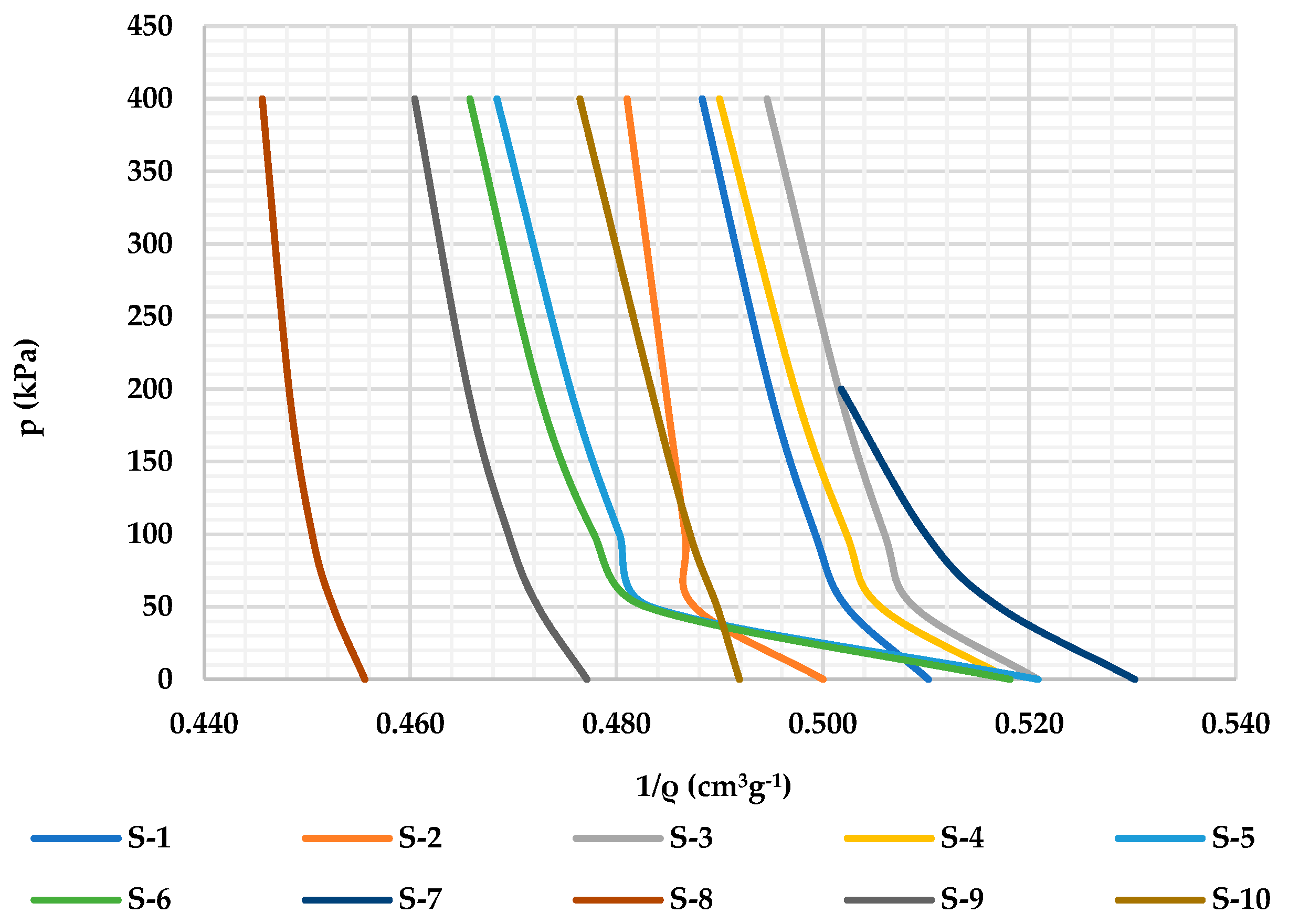
Figure 1. The results of soil stiffness shown as a dependence of inverse density under different loads.
Applsci 14 06790 g001
Figure 2. The test field [16].
Applsci 14 06790 g002
Figure 3. Example of measured cavity shape processed using AutoCad Civil 3D software [16].
Applsci 14 06790 g003
Figure 4. The graphical analyses of (a) the results of the water content and the volume of cavity depend-ence and (b) the correlation between the water content and the volume of cavity.
Applsci 14 06790 g004
Figure 5. The graphical analyses of (a) the results of the plasticity index and the volume of cavity dependence and (b) the correlation between the plasticity index and the volume of cavity.
Applsci 14 06790 g005
Figure 6. The volume of cavity produced by different type of explosives (a) ANFO explosive, (b) ammonium nitrate powder, and (c) water gel explosive. (d) Comparison of the volume of cavity for different types of explosives.
Applsci 14 06790 g006
Figure 7. Summary correlations for ANFO and powdered explosives: (a) dependence of water content and volume of cavity and (b) dependence of plasticity index and volume of cavity.
Applsci 14 06790 g007
Table 1. The results of the soil parameters.
Designation of SoilMoisture Content [%]Grain Size DistributionLiquid Limit
wL [%]
Plasticity Limit wp [%]Plast.
Index
Ip [%]
Cons.
Index
Ic [-]
Solid Particle Density
ρs [g/cm3]
Gravel [%]Sand [%]Silt [%]Clay [%]
S-128.03.53.155.637.85122290.792.71
S-224.00.06.277.116.73422120.832.70
S-332.70.03.968.028.14424200.572.75
S-431.60.37.271.220.84023170.492.74
S-526.40.04.864.530.83922170.782.76
S-627.70.09.261.629.23621150.642.75
S-735.20.010.471.218.54829190.662.66
S-817.80.017.965.916.2292180.772.72
S-922.10.049.935.914.2282170.632.70
S-1025.80.05.073.421.63520150.612.71
Table 2. Parameters of the studied explosives.
Type of Explosive
(Trade Name)
Density
(g/cm3)
Velocity of Detonation
(Measured)
(m/s)
Theoretical Heat of Detonation
(Literature and Producer Declaration)
(KJ/kg)
ANFO (Pakaex)0.9020003597
Ammonium nitrate powder explosive
(Permonex)
1.0540004276
Watergel (Riogel)1.2545764591
Table 3. JWL constants calculated by EXPLO5 V7.01.01.
Type of ExplosiveA
(Mbar)
B
(Mbar)
R1
(-)
R2
(-)
ω
(-)
D
(cm/μs)
P
(Mbar)
E
(Gerg/mm3)
ANFO (Pakaex)0.062805 [15]0.001513
[15]
2.193732 [15]0.464714 [15]0.177879 [15]0.304939 [15]0.01933323 [15]0.029706
[15]
Ammonium nitrate
Powder (Permonex)
0.790230.012574.67970.95290.19330.40220.03790.0318
Gel (Riogel)2.389310.0226555.2033691.0543840.1584590.45870.058280.0412
Table 4. Validation results.
Type of ExplosiveCavity Experimental
[dm3]
Cavity Model
[dm3]
Deviation
[%]
ANFO (Pakaex)752 [15]839 [15]12.9 [15]
Ammonium nitrate
powder explosive (Permonex)
8357896.1
Table 5. Numerical simulation results.
Field Designation
of Soil
ANFO Ammonium Nitrate Powdered Explosive
Volume of Cavity
[dm3]
Volume of Cavity
[dm3]
S-1863787
S-211121917
S-3300291
S-4378356
S-51033868
S-610951027
S-7655572
S−-843332202
S-923772304
S-1017901193
Table 6. Comparison of parameters for studied explosive and cavity formation results.
Type of ExplosivePressure
[GPa]
Volume of Gas Products
[dm3/kg]
Volume of Cavity
Formation
[dm3]
ANFO 0.86698863
Ammonium nitrate powder3.24628787
Water gel5.83593862
Disclaimer/Publisher’s Note: The statements, opinions and data contained in all publications are solely those of the individual author(s) and contributor(s) and not of MDPI and/or the editor(s). MDPI and/or the editor(s) disclaim responsibility for any injury to people or property resulting from any ideas, methods, instructions or products referred to in the content.