Article

Coupled Non-Ordinary State-Based Peridynamics Model for Ductile and Brittle Solids Subjected to Thermal Shocks

1
National Key Laboratory of Nuclear Reactor Technology, Nuclear Power Institute of China, Chengdu 610200, China
2
State Key Laboratory of Structural Analysis, Optimization and CAE Software for Industrial Equipment, Department of Engineering Mechanics, School of Mechanics and Aerospace Engineering, Dalian University of Technology, Dalian 116024, China
*
Author to whom correspondence should be addressed.
Appl. Sci. 2024, 14(16), 6927; https://doi.org/10.3390/app14166927
Submission received: 26 June 2024 / Revised: 26 July 2024 / Accepted: 6 August 2024 / Published: 7 August 2024
(This article belongs to the Section Applied Thermal Engineering)

Abstract

:
A coupled thermomechanical non-ordinary state-based peridynamics (NOSB-PD) model is developed to simulate the dynamic response arising from temperature and to predict the crack propagation with thermal shocks in brittle and ductile solids. A unified multiaxial constitutive model with damage growth is proposed to simultaneously describe the ductile and brittle fracture mechanisms. The main idea is the use of Lemaitre’s model to describe ductile damage behavior and the use of tensile strength instead of yield stress in Lemaitre’s model to describe brittle damage behavior. A damage-related fracture criterion is presented in the PD framework to predict crack propagation, which avoids numerical oscillations when using the traditional bond stretch criterion. To capture the dynamic plastic response induced by thermal shocks, the time and stress integration are achieved by an alternating solving strategy and implicit return-mapping algorithm. Several numerical examples are presented to show the performance of the proposed model. Firstly, a thermomechanical problem simulation based on both the proposed model and the FEM illustrate the accuracy of the proposed model in studying the thermal deformation. Moreover, a benchmark brittle fracture example of the Kalthoff–Winkler impact test is simulated, and the crack path and angle are similar to the experimental observations. In addition, the simulation of ductile fracture under different loads illustrates the effect of temperature on crack propagation. Finally, the simulation of the 2D quenching test shows the ability of the proposed model in predicting crack propagation under thermal shocks.

1. Introduction

The capability of industrial equipment to resist fractures during its whole service life is directly related to the solid materials used in industrial manufacturing. Numerical simulation is an economical and efficient way to study the relationship between the mechanical properties of such materials and fracture problems in engineering applications. With the demand for industrial equipment for wide applications, there is an increasing need for structural components operating in extremely high-temperature environments. However, the potential risk of accidents brings significant challenges in assessing the ability of structures such as engine nozzles, metallic pressure vessels and ceramic insulation coatings to withstand fractures under thermal shock. Therefore, it is of great importance to develop an accurate computational method to simulate the ductile or brittle fracture behaviors under thermomechanical deformation and predict the crack propagation arising from thermal stress.
So far, some methods based on classical continuum mechanics have been proposed to investigate the thermomechanical behavior involving fractures, such as the boundary element method (BEM) [1,2] and the finite element method (FEM) [3]. Incorporating damage mechanics, these methods have been utilized to simulate the multiple crack patterns of brittle solids in quenching tests. However, the implementation of the above methods is inevitably faced with some difficulties in describing the crack initiation and propagation, due to over-simplified crack modeling and mesh dependence. To overcome such limitations and model arbitrary thermomechanical crack patterns, a number of novel methods were developed, including the extended finite element method (XFEM) [4], the extended element free Galerkin method (XEFG) [5], the radial point interpolation method (RPIM) [6], and smoothed particle hydrodynamics (SPH) [7,8]. These methods allow for better tracking of crack paths. Moreover, the cohesive zone model [9] and the phase-field (PF) model [10] have also been extended to simulate fracture problems with thermal effects [11,12], further providing an effective approach for researchers. Although the aforementioned numerical methods and models can be applied for crack analysis under thermal shocks, some extra computational efforts such as element delete techniques [13] and damage equations [14] still introduce numerical difficulty due to the discontinuous crack surfaces.
Peridynamics (PD), as an alternative non-local model in solid mechanics, was formulated in terms of space integration instead of differentiation in the governing equations by Silling [15]. The main advantage is that the integration equation allows crack propagation at any paths without a special crack growth assumption. The original version of the PD model is called the bond-based PD (BB-PD) model [16,17], where the assumption of equal pairwise force states results in a limitation on Poisson’s ratio. To overcome this constraint, the state-based PD (SB-PD) model [18] was further proposed, including the ordinary state-based PD (OSB-PD) model [19,20,21] and the non-ordinary state-based PD (NOSB-PD) model [22,23,24]. As a more general form of the SB-PD model, the NOSB-PD model has widely attracted attention because of its advantage of easy application of classical continuum mechanics (CCM) to study complex material models, including plastic [25,26], visco-plasticity [27], and hyperelastic [28].
For thermomechanical problems, some excellent works based on the PD model have been conducted. Early, the 1-D and 2-D PD formulations based on the BB-PD model were developed by Bobaru and Duangpanya [29,30]. Oterkus et al. [31] extended the heat conduction equation with the SB-PD model based on the Lagrangian formalism. Subsequently, many studies of thermoelastic, thermoplastic, and thermodynamic problems [32,33,34,35,36] were investigated on the basis of the theoretical foundation of modeling thermal problems. These works lay a solid theoretical foundation for modeling thermal shock problems involving brittle fractures. Currently, the study of thermal-shock-induced fracture mainly use the BB-PD [37,38] and the OSB-PD models [39,40]. Although these studies have demonstrated the good performance of the PD model in dealing with thermal shock problems, half of them have focused on fracture in brittle materials, which leads to difficulties in applying these methods for modeling ductile materials. Therefore, it is very promising to use the advantage of the NOSB-PD model to study more complex materials under thermal shocks.
The fracture criterion is also a non-negligible part in the simulation of the fracture problem. In fracture mechanics, the critical energy release rate is one of the most commonly used material fracture properties that determines when a material will fracture [41]. According to the linear elastic fracture mechanics (LEFM), the value of the critical energy release rate can be measured by the geometry of the specimen and external loading parameters at a specific crack configuration [42]. In the PD framework, the situation is somewhat different. As a non-local meshless approach, the PD model can calculate the energy release rate by calculating the fractured bonds cut at the surface [16,43]. In other words, the relationship between the energy release rate and the elongation of the bond can be established. Thus, the most commonly used fracture criterion in the PD model is the bond stretch criterion. However, this criterion is seldom applied in the NOSB-PD framework, where the stress [44,45] and strain criteria [46,47] are more applicable. For brittle materials, either the stress or strain criterion can describe the fracture behavior well. For ductile materials, the fracture behavior is not only related to stress and strain, but also to damage behavior. This leads to the fact that different materials often require different fracture criteria. Therefore, the development of a fracture criterion for both ductile and brittle materials is very promising for applications.
Based on the advantage of the NOSB-PD in combining with the CCM theory, this work aims to develop a coupled thermomechanical non-ordinary state-based peridynamics (NOSB-PD) model for accurately predicting crack propagation arising from thermal shocks in ductile and brittle solids. In this model, a unified multiaxial constitutive model with damage is proposed to describe both ductile and brittle behaviors, in which the distinction is achieved by using different physical variables representing different fracture mechanisms. To suppress the numerical oscillations due to the zero-energy modes, a damage-related fracture criterion is considered instead of the traditional criterion (e.g., the bond criterion). Furthermore, full explicit time integration is used for the accurate response of coupled thermodynamic effects.
This paper is organized as follows. The basic theory of the NOSB-PD model for the thermodynamic problem is described in Section 2, including the stabilization method for thermal problems. The multiaxial plastic constitutive model involving damage is given in Section 3. The time integration and stress integration strategies are shown in Section 4. The ability of the proposed model to simulate thermodynamic problems and predict the crack propagation in ductile or brittle solids under thermal shocks is verified by several represented examples in Section 5. Final conclusions are drawn in Section 6.

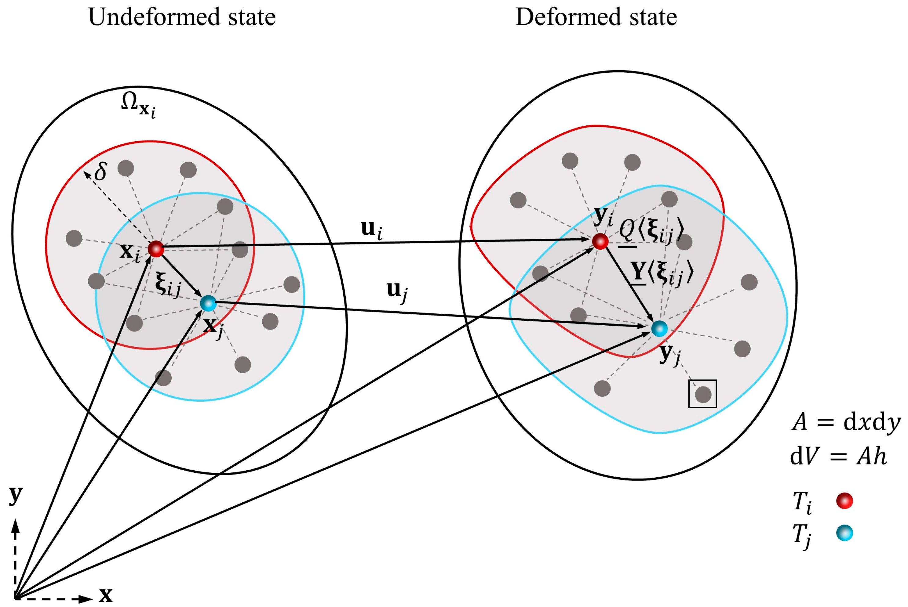
2. Basic Theory of the Non-Ordinary State-Based Peridynamics Model

2.1. Thermomechanical PD Equations

In the PD theory, a continuum solid is discretized into a set of individual material points x i , i = 1,2 , 3 , N . Figure 1 illustrates the undeformed and deformed PD states related to x i . Here, y i = x i + u i is the position in the deformed configuration, and u i is the displacement vector of point x i . Furthermore, Ω x i is the neighborhood horizon of x i with a given radius δ , and x j is a neighborhood point. For mechanical problems, X _ ξ i j = ξ i j = x j x i is defined as the bond between two interacting points, and the corresponding deformation vector state is defined as Y _ ξ i i j = y j y i . For thermal problems, the heat temperature scalar state is defined as Q _ ξ i j = T j T i , where T i and T j represent temperatures related to points x i and x j .
According to pioneering works, the governing PD equations for thermomechanical problems at time t for material point x i are given by [48]:
ρ u ¨ x i , t = Ω x i t _ x i , t ξ i j t _ x j , t ξ j i d V x j + b x i , t ,
ρ c T ˙ x i , t = Ω x i τ _ x i , t ξ i j τ _ x j , t ξ j i d V x j + s b x i , t ,
where ρ is the density, u ¨ is the acceleration vector, T ˙ is the derivative of the temperature, d V x j is the volume associated with point x j , b is the external body force, c is the specific heat capacity, s b is the volumetric heat generation per unit mass, and t _ and τ _ are the force vector state and heat flow scalar state related to the bond.

2.2. Correspondence Material Model for Thermomechanical Problems

Based on the correspondence material model in the PD theory, the force vector state t _ and heat flow scalar state τ _ are related to the non-local deformation gradient F ¯ and the non-local temperature gradient G ¯ [43], that are
F ¯ = Ω x i ω _ ξ i j Y _ ξ i j X _ ξ i j d V x j K ,
G ¯ = Ω x i ω _ ξ i j Q _ ξ i j X _ ξ i j d V x j K ,
where ω _ is the influence function and K = Ω x i ω _ ξ i j X _ ξ i j X _ ξ i j d V x j is the shape tensor defined by Silling [18]. In this work, the influence function is chosen as ω _ ξ i j = 1 ξ i j δ .
Considering the assumption of small deformation in this work, the force vector state t _ and heat flow scalar state τ _ can be given by [48],
t _ x i , t ξ i j = ω _ ξ i j σ i K i 1 ξ i j ,
τ _ x i , t ξ i j = ω _ ξ i j q i K i 1 ξ i j ,
where σ is the Cauchy stress tensor and q is the heat flux density vector.
For mechanical problems, the stress–strain relationship that involves plastic behaviors and temperature effects is given by [48],
σ = C ε ε p ε T ,
where C is the elastic tensor, ε = 1 2 F ¯ I T + 1 2 F ¯ I is the total strain tensor, ε p is the plastic strain tensor, ε T = α T I is the thermal strain tensor, and α is the coefficient of thermal expansion.
For thermal problems, the heat flux is given by [48],
q = k G ¯ ,
where k is the thermal conductivity tensor.

2.3. Stabilization Method

In practice, the correspondence material model often suffered from numerical oscillations due to the zero-energy modes [49]. To avoid such numerical errors, an improved stabilization method based on the idea of the work of Wan et al. [50] is presented to improve computational stability in handling the coupling thermomechanical effect.
Briefly, the stabilized force vector state t _ s x i , t ξ i j is given by [50],
t _ s x i , t ξ i j = t _ x i , t ξ i j + G 0 ω _ ξ i j C K 1 z _ ξ i j ,
where G 0 is a positive constant on the order of 1 and z _ ξ i j = Y _ ξ i j F ¯ ξ i j is the nonuniform deformation state.
Moreover, the stabilized heat flow scalar state τ _ s x i , t ξ i j can be expressed as
τ _ s x i , t ξ i j = τ _ x i , t ξ i j + G 0 ω _ ξ i j k K 1 z _ ξ i j ,
where z _ ξ i j = Q _ ξ i j G ¯ ξ i j is the nonuniform temperature state.

3. Constitutive Model

3.1. Multiaxial Constitutive Model with Damage

The J 2 plastic model with damage variable D , known as the Lemaitre’s damage model, is considered in this work [51] for describing ductile and brittle fracture behaviors. In this model, the damage variable D = 1 represents the total fracture of materials and D = 0 represents intact materials. Moreover, the relationship between effective stress σ D and real stress σ in the theory of continuum damage mechanics (CDM) is given by [51]:
σ D = σ 1 D .
For ductile fracture problems, the yield function is given by [51]
f = σ ¯ D σ Y ε ¯ p = 0 ,
where σ ¯ represents the von Mises equivalent stress, σ Y denotes the yield stress, and ε ¯ p is the accumulated plastic strain.
The hardening law considered in this work is given by σ Y = σ Y 0 + A ε ¯ p , where σ Y 0 is the initial yield stress and A is the hardening parameter.
Combining the maximum dissipation principle [52] and Lemaitre’s work [53], the evolution of the incremental plastic strain, accumulated plastic strain, and damage can be expressed as [53]
ε p = γ f σ ,
ε ¯ p = γ 1 D ,
D = D ¯ ε ¯ p ε ¯ f p ε ¯ 0 p R v , i f ε ¯ p ε ¯ 0 p   a n d   σ m 0 0 , i f   n o t ,
where γ is the plastic multiplier, R v = 2 3 1 + ν + 3 1 2 ν σ m σ ¯ 2 is the triaxiality function, σ m is the hydrostatic pressure, σ m 0 ensures that the material does not fracture under compression, D ¯ is the critical damage value, ε ¯ f p is the fracture strain, and ε ¯ 0 p is the corresponding strain at the beginning of damage.
For brittle fracture problems, the aforementioned damage model can be simplified as a subtle modification of Equation (15), i.e., adjusting ε ¯ 0 p to 0 , ε ¯ f p to a tiny value ε ¯ t p , and σ Y 0 to the tensile strength σ t . The main idea is constructed by considering the material as an ideal plastic material and reducing the deformation in the plastic stage to simulate brittle fracture. Based on this approach, it is not only easier to use the tensile strength σ t as a failure criterion but also to spontaneously describe the stress degradation behavior of the material to avoid numerical oscillations caused by the sudden loss of bond force. Figure 2 gives a schematic diagram of the damage evolution during ductile and brittle fracture problems, where E is Young’s modulus.

3.2. Failure Criterion

Generally, the simulation of fracture in the PD model is utilized by multiplying a value μ ξ on the force tensor state. There are many available criteria that have performed well in numerous studies, such as bond stretch [16,54], equivalent strain [44,45], and strength stress [46,47]. The bond stretch criterion related to the LEFM is one of the most popular. In this criterion, the bond is broken if the stretch s = Y _ X _ X _ is over the critical value, that is [16],
μ ξ = 0 , s s 0 1 , s < s 0 .
However, the application of the above criterion for thermomechanical problems may face some difficulties. On the one hand, the bond stretch is no longer linearly related to external loads for plastic materials. On the other hand, the stress waves generated by high-velocity impact inevitably lead to numerical oscillations in the value of the bond stretch. Therefore, a special failure criterion related to the damage variable is proposed in this work that can describe ductile and brittle fracture simultaneously incorporated with the proposed multiaxial constitutive model. The bond fracture state between material points x i and x j is given by
μ ξ i j = 0 , D i D ¯   &   D j D ¯ 1 , o t h e r s ,
where the critical damage D ¯ is set to be 0.99 in this work. Then, the fracture level d of a PD material point x i is given by [16]
d x i = 1 Ω x i μ ξ i j d V x j Ω x i 1 d V x j .

4. Numerical Implementation

4.1. Time Integration

In this work, the forward Euler method and a step-by-step iterative technique are adopted to solve both mechanical and thermal problems. The time increment for dynamic phenomena is dependent on the stress wave propagation speed in materials, while the time increment for thermal transfer depends on the thermal diffusivity of materials. Generally, the time scales for mechanical dynamic problems are much smaller than those for thermal problems. Therefore, the time increment t is chosen as [55]
t < l c w .
where l is the size of the material points and c w is the speed of the stress wave in materials.
Moreover, an alternating solve strategy is adopted here to capture the structural dynamic response during thermal shocks. The mechanical simulation will update after each step in the thermal simulation.

4.2. Stress Integration

In this work, the one-equation integration algorithm [56] is adopted for the multiaxial plastic constitutive model with damage. In this algorithm, the stress state σ , damage variable D , and plastic strain ε p for the given total strain ε require the solution of only one scalar non-linear equation. Briefly, the actual stress, plastic strain, internal variable, and damage variable at time step n + 1 can be iteratively solved by
w γ w n + γ w γ D ¯ ε ¯ f p ε ¯ 0 p R v = 0 .
where n denotes the time step for mechanical problems. Furthermore, w γ = 1 D n + 1 is the material integrity and is given by [56]
w γ = 3 G γ σ ¯ ~ t r i a l σ Y .
where σ ¯ ~ t r i a l = 3 2 s ~ t r i a l is the effective elastic trial von Mises equivalent stress and s ~ t r i a l is the deviatoric trial stress tensor of the elastic trial stress tensor σ ~ t r i a l = C ε . The non-linear equation is solved by utilizing the Newton–Raphson method, and details are given in [48].

5. Numerical Examples

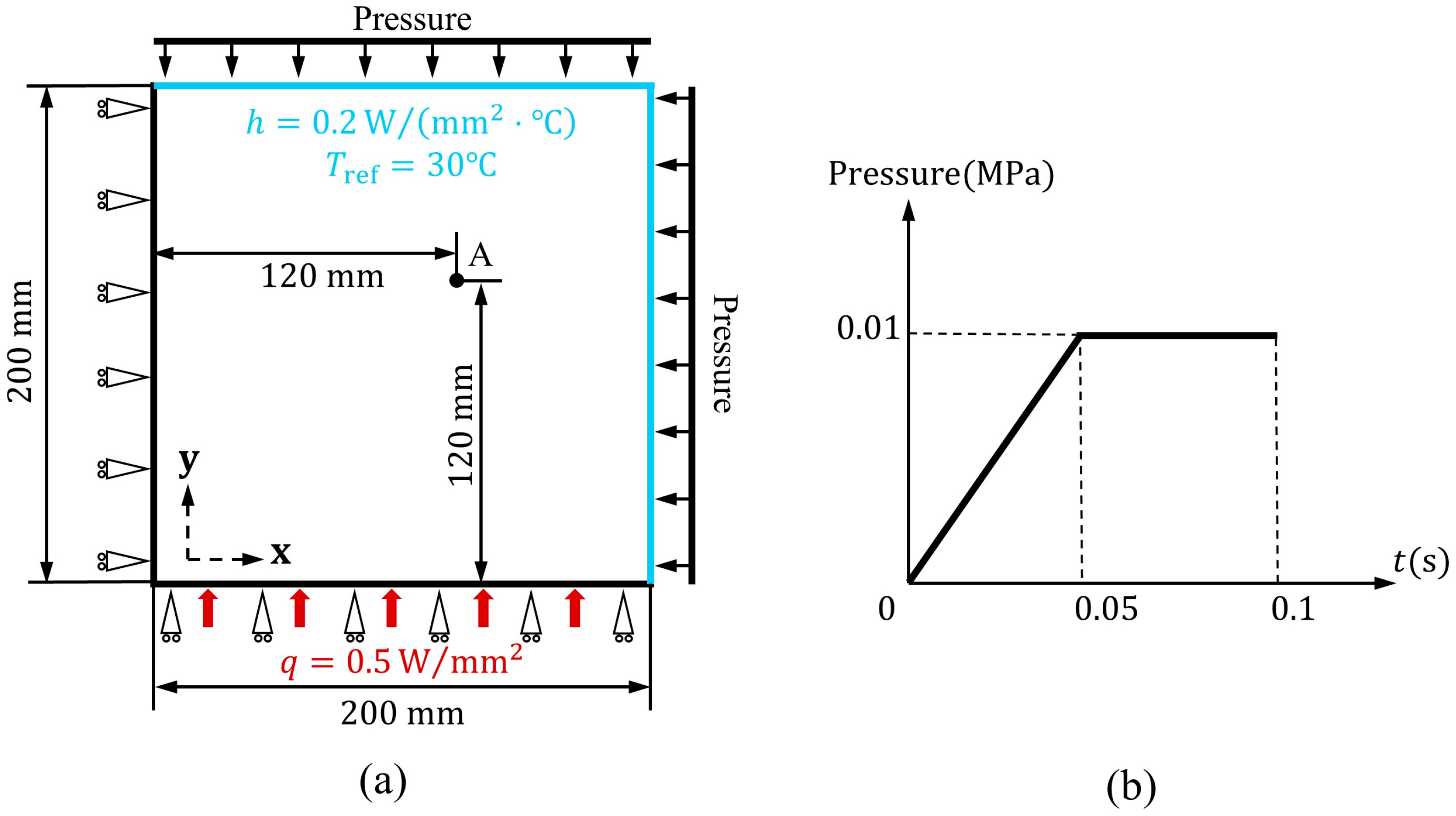
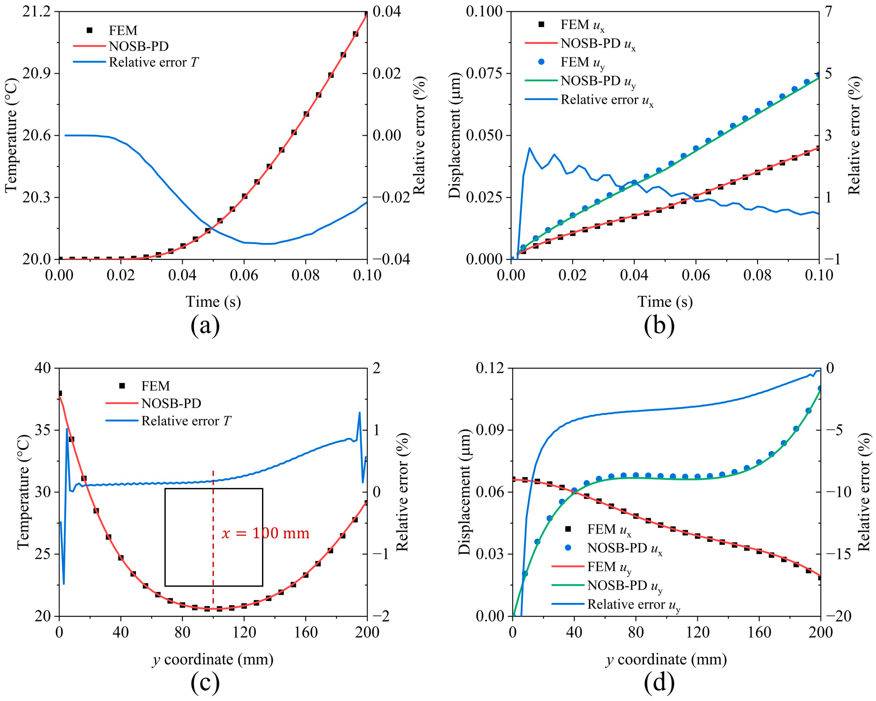
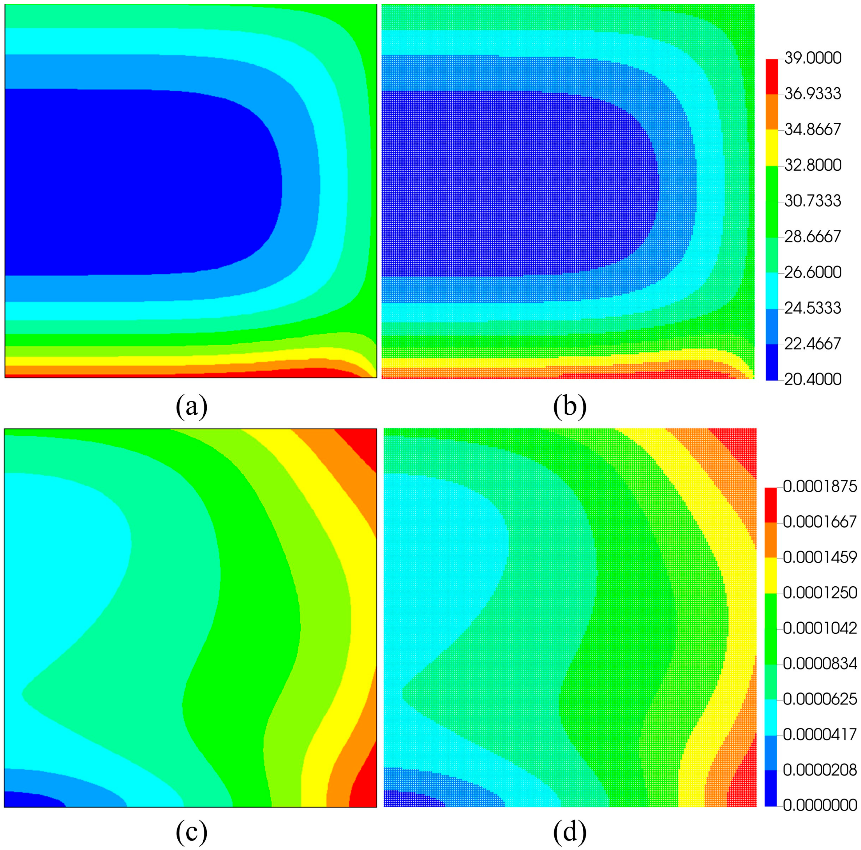
5.1. Thermodynamic Analysis of Plate

In order to validate the accuracy of the proposed PD model in simulating thermodynamic response, a plate under thermal shock load is considered. The geometry and loading conditions are shown in Figure 3. The material properties are given in Table 1. The horizon δ is set to be 3.0   m m , and l is set to be 1.0   m m . The initial temperature of the structure is set to be 20   ° C . A heat flux q is applied on the structure bottom. The convective heat transfer boundary is applied on the top and right surfaces with coefficient h and reference temperature T r e f . The time increment is chosen as Δ t = 0.2   μ s .
Figure 4 shows results simulated by the proposed model and the FEM (obtained by ANSYS 19.0 ×64). There is good agreement between the history curves of point A in the temperature field [see Figure 4a], which verifies the accuracy of the proposed model for transient thermal problems. Moreover, the displacement histories [see Figure 4b] and distributions along the y direction [see Figure 4c,d] further indicate that the proposed model can handle the coupled effect due to the temperature changing. It can be seen that the absolute value of the relative error of temperature and displacement at point A during thermal diffusion is less than 0.04 % and 3 % , respectively. The relative error of temperature along the path x = 100   m m is larger at the geometric boundary and smaller in the center region. In addition, the relative error of displacement is greater than 20 % near y = 0   m m and decreases with y-coordinate increase. This can be attributed to the deviation of the material point coordinates from the actual boundaries of the structure, which is usually 0.5 l . These discrepancies have been shown to be further reduced by decreasing the horizon radius or refining the discretization [57]. Figure 5 shows the contour plots of the temperature and displacement utilized in the different models at t = 0.1   s . These results verify the accuracy of the proposed model in simulations of thermodynamic problems.

5.2. Kalthoff–Winkler Impact Test

The Kalthoff–Winkler test, as a classic benchmark problem for studying dynamic fracture and peridynamics simulation results [44,58], is considered here to verify the ability of the proposed model and the fracture criterion. It can be observed that a brittle fracture mode occurs with impact speed of 32   m / s , and the crack propagates around 70 ° with respect to the pre-existing cracks during the test. The specimen geometry and loading boundary are shown in Figure 6.
Both the bond stretch criterion and the proposed criterion are used to simulate this test. The critical stretch s 0 is set to be 0.01 in the bond stretch criterion. The yield stress is set to be the ultimate tensile 2000   M P a [58], and the fracture strain is considered to be very small in the proposed criterion. Other material properties are given in Table 2. The horizon δ is set to be 0.75   m m , and l is set to be 0.25   m m . The time increment is chosen as Δ t = 0.087   μ s . To save computational costs, a half of the model is taken.
The results of crack propagation are shown in Figure 7. It can be seen that the cracks start to initiate at about 26.1   μ s , and then propagate at the angle of 81 ° and 69 ° for applying the different fracture criteria, respectively. In the case of the bond stretch criterion, the angle of crack propagation is far from the experimental result [59]. Moreover, the rate of crack propagation is slower compared with the case of the proposed criterion and exhibits an unreasonable crack path at t = 113.1   μ s . In contrast, the proposed criterion gives more stable results and is in good agreement with the pioneer’s work [60,61].
Figure 8 further shows contour plots of von Mises stress obtained by the two criteria, which demonstrates why the application of the bond stretch criterion in the NOSB-PD framework to simulate the fracture problem often fails. As shown in Figure 8, the stress level is increasing at the bottom of the pre-existing crack and leads to crack initiation. However, using the bond to determine a crack cannot guarantee that the deformation at the crack tip will not produce the numerical oscillation, which leads to chaotic displacement and extreme stress [see Figure 8a]. Instead, using the proposed criterion gives a more stable displacement field and low effect of stress concentration [see Figure 8b].

5.3. Thermal Effect in the Fracture

To further demonstrate the capability of the proposed PD model to simulate the ductile fracture involving thermal effects, a series of simulations of the crack extension of an asymmetric notched plate under different loadings is considered. The geometry and loading conditions of the specimen are shown in Figure 9. Two loading cases are given below:
  • The velocity of v = 20   m m / s is applied to both ends of the specimen while the temperature is set to be constant.
  • The specimen is fixed at both ends while a temperature change T ˙ = 20,000   ° C / s is applied.
Moreover, the material properties are given in Table 3, and the transient heat conduction is ignored in case ii. The horizon δ is set to be 0.6   m m , and l is set to be 0.2   m m . The time increment is chosen as Δ t = 0.01   μ s .
The crack initiation times of the specimen under the two loading cases are 2.4   m s and 7.4   m s , respectively. Figure 10 shows the contour plots of von Mises stress result in the two cases at crack initiation time. It can be seen that there is a huge difference in stress distribution. In case i, the high stress level is mainly concentrated in the center of the specimen. However, the stress in the specimen is more uniform under the thermal effect. This leads to a difference in the further crack propagation.
Figure 11 shows the crack propagation process of two cases, including contour plots of damage D and fracture level d . For case i, the crack initiates at the two notches and gradually expands along the oblique direction of the sample with the loading of uniaxial tensile displacement. For case ii, the crack also appears at both notches. However, the cracks extend obliquely and then laterally to the other side of the notch. In addition, the damage distribution is also different in the two cases. In case i, the damage is mainly distributed within the area of the line connecting the two notches. In case ii, the damage distribution is similar to case i at the initial fracture moment. With the crack propagation, most of the areas of the specimen are damaged, which leads to a different crack form with respect to case i. These results demonstrate that the proposed PD model has the ability to simulate the ductile fracture, and the temperature effect cannot be neglected when the fracture analyses are performed on the structure.

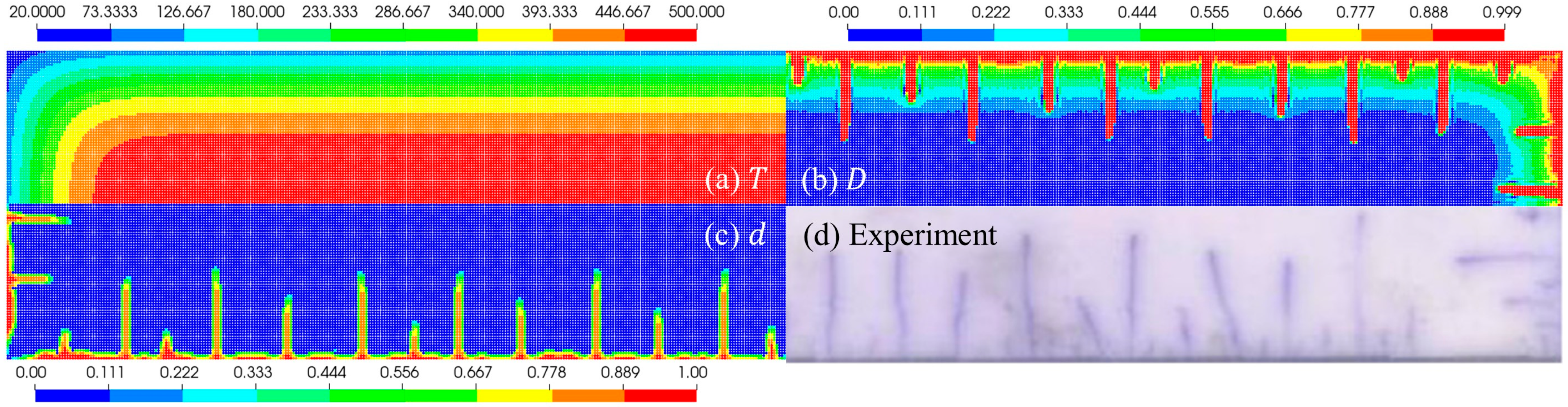
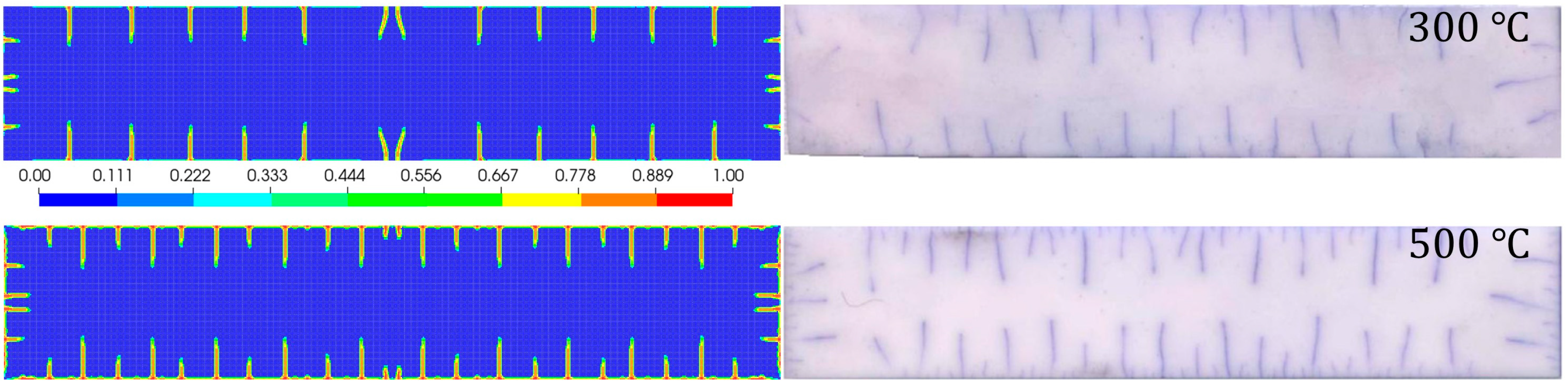
5.4. The 2D Quenching Test

In this example, the complex crack patterns arising from thermal shocks are investigated by the proposed NOSB-PD model. In previous experiments, the ceramic slabs were heated to an initial temperature T 0 , which ranged from 300   ° C to 600   ° C , and then the heated specimen was dropped into a water bath of T r e f = 20   ° C by free-fall [3]. The 2D model is considered and the geometry and boundaries are given in Figure 12. To save computational cost, a one-quarter model (lower left part) replaces the full-size model. The initial temperature is set to be 500   ° C , and the convective heat transfer coefficient h between solid and water is set to be 700,000   W / m 2 ° C [37]. Moreover, the horizon δ is set to be 0.25   m m , and l is set to be 0.083   m m . In addition, the mechanical properties of the ceramic slab given in Table 4 are approximately unchanged in the range 200   ° C to 600   ° C . The time increment is chosen as Δ t = 0.005   μ s . The total computational time is 200   m s .
Figure 13 shows contour plots of the temperature, damage, and crack growth paths compared with the experiment result at the final time. It can be seen that the temperature undergoes significant cooling. The accompany temperature gradient results in damage to the surfaces of the specimen. With the change in damage state, cracks further occur. The results also show that the thermal cracks are approximately parallel and equally spaced of similar length, which demonstrates that the numerical crack pattern is quite similar to the experimental one [3].
Figure 14 also shows the evolution of temperature fields and crack growth paths during the simulation. At the early stage of thermal shock, cracks are initiated on the left and bottom surfaces at t = 10   m s . In the rest of the surface area, a series of small cracks almost at equal spacing are generated. These cracks occur simultaneously due to a huge temperature gradient. Subsequently, only a few cracks continue to propagate upwards [see Figure 14, ( t = 30   m s )]. During the propagating process, some cracks grow faster and become long cracks, while others grow in a much slower way and remain short in the end [see Figure 14, ( t = 100 200   m s )]. It can be found that the periodical and hierarchical characteristics of crack spacing and length that are formed in the numerical simulations are in good agreement with the experimental observations. Moreover, the significant temperature jumping across all the bent thermal cracks can also be captured in the simulation using the proposed model.
In addition, another case with initial temperature 300   ° C is considered to further demonstrate the ability of the proposed NOSB-PD model in simulating crack propagation under different thermal shocks. Figure 15 illustrates the final crack patterns of the numerical and experimental results in the quenching tests. It can be observed that the number of cracks increases with initial temperature. The result, considering an initial temperature of 300   ° C , also shows the absence of the distinct hierarchy of crack lengths, which can be attributed to the effect of the fracture strain ε ¯ f p . In fact, a smaller ε ¯ f p will make the material more brittle in terms of its fracture property. These results imply the effectiveness of the proposed NOSB-PD model for simulating and predicting thermodynamic problems involving fractures and thermal shocks.

6. Conclusions

To simulate the coupled thermomechanical behaviors and crack propagation in ductile and brittle solids subjected to thermal shocks, a coupled thermodynamic non-ordinary state-based peridynamics (NOSB-PD) model is proposed. The proposed model can qualitatively capture both ductile and brittle fracture modes of solids through a unified multiaxial constitutive model and fracture criterion. For ductile fracture in solids, the material degradation behavior and crack propagation are related to the plastic strain. For brittle fracture in solids, the degradation behavior of the material occurs rapidly. Moreover, the brittle fracture simulation is achieved by substituting the strength stress for the yield stress and adjusting the yield criterion. In addition, a more suitable fracture criterion related to the damage variable is developed to describe the crack paths, which does not require any additional equations in the PD framework. Numerical results of the comparison with commercial software show the accuracy of the proposed model. The simulation results show that the proposed model predicts an inclined linear crack path in brittle solids, which is consistent with experimental observations. Furthermore, simulation of ductile solids under different loads is also conducted, and the effect of temperature on crack path is discussed. The results show that the uniform temperature change prevented the cracks from converging together in the center of the specimen although the crack initiation locations are the same for the two different loads. Finally, the ability of the proposed model to competently simulate both ductile and brittle fracture is demonstrated by an engineering example of quenching simulation. In practice, the simulation of ductile and brittle fracture no longer requires a specific corresponding fracture model, but only the corresponding yield and tensile strength. These results show the great potential of the proposed model in dealing with fracture problems in both ductile and brittle solids under thermal shocks. However, parameters in the fracture model are dependent on tests and experiments, and more accurate parameter values are still needed in practice for accurate simulations. Therefore, further research could focus on constructing simpler and more efficient fracture models that handle more complex crack patterns.

Author Contributions

Formal analysis, H.Z.; investigation, Y.Z.; methodology, H.L., H.Z. and X.S.; resources, X.B.; software, X.S.; visualization, B.W.; writing—original draft, H.Z.; writing—review and editing, H.L. All authors have read and agreed to the published version of the manuscript.

Funding

This research was funded by The National Natural Science Foundation of China (grant number 12102416).

Institutional Review Board Statement

Not applicable.

Informed Consent Statement

Not applicable.

Data Availability Statement

Data is contained within the article.

Conflicts of Interest

The authors declare no conflict of interest.

Nomenclature

x Material points
N The number of material points
y The position in the deformed configuration
u The displacement vector
Ω x i The neighborhood horizon of x i
δ The radius of the neighborhood horizon
X _ ξ i j The bond between two interacting points
Y _ ξ i j The corresponding deformation vector state
T The temperature
Q _ ξ i j The heat temperature scalar state
ρ The density
u ¨ The acceleration vector
T ˙ The derivative of the temperature
d V x j The volume associated with point x j
b The external body force
c The specific heat capacity
s b The volumetric heat generation per unit mass
t _ The force vector state
τ _ The heat flow scalar state
F ¯ The non-local deformation gradient
G ¯ The non-local temperature gradient
ω _ The influence function
K The shape tensor
σ The Cauchy stress tensor
q The heat flux density vector
C The elastic tensor
ε The total strain tensor
ε p The plastic strain tensor
ε T The thermal strain tensor
α The coefficient of thermal expansion
k The thermal conductivity tensor
t _ s The stabilized force vector state
G 0 A positive constant on the order of 1
z _ ξ i j The nonuniform deformation state
τ _ s The stabilized heat flow scalar state
z _ ξ i j The nonuniform temperature state
D The damage variable
f The yield function
σ ¯ The von Mises equivalent stress
σ Y The yield stress
ε ¯ p The accumulated plastic strain
σ Y 0 The initial yield stress
A The hardening parameter
ε p The incremental plastic strain
γ The plastic multiplier
D The incremental damage
R v The triaxiality function
σ m The hydrostatic pressure
D ¯ The critical damage value
ε ¯ f p The fracture strain
ε ¯ 0 p The corresponding strain at the beginning of damage
σ t The tensile strength
E Young’s modulus
μ ξ The scalar reflecting fracture state
s The bond stretch
s 0 The critical value of bond stretch
d The fracture level
t The time increment
l The size of material points
c w The speed of the stress wave in materials
w γ The material integrity
σ ¯ ~ t r i a l The effective elastic trial von Mises equivalent stress
s ~ t r i a l T he deviatoric trial stress tensor
σ ~ t r i a l The elastic trial stress tensor
q The heat flux
T r e f The reference temperature
v Poisson’s ratio
t The time
v The velocity

References

  1. Bahr, H.A.; Weiss, H.J.; Maschke, H.G.; Meissner, F. Multiple crack propagation in a strip caused by thermal shock. Theor. Appl. Fract. Mech. 1988, 10, 219–226. [Google Scholar] [CrossRef]
  2. Tarasovs, S.; Ghassemi, A. Self-similarity and scaling of thermal shock fractures. Phys. Rev. E 2014, 90, 012403. [Google Scholar] [CrossRef] [PubMed]
  3. Li, J.; Song, F.; Jiang, C.P. Direct numerical simulations on crack formation in ceramic materials under thermal shock by using a non-local fracture model. J. Eur. Ceram. Soc. 2013, 33, 2677–2687. [Google Scholar] [CrossRef]
  4. Menouillard, T.; Belytschko, T. Analysis and computations of oscillating crack propagation in a heated strip. Int. J. Fract. 2011, 167, 57–70. [Google Scholar] [CrossRef]
  5. Wang, H.S. An extended element-free Galerkin method for thermo-mechanical dynamic fracture in linear and nonlinear materials. Comput. Mater. Sci. 2015, 98, 366–371. [Google Scholar] [CrossRef]
  6. Nguyen, N.T.; Bui, T.Q.; Nguyen, M.N.; Truong, T.T. Meshfree thermomechanical crack growth simulations with new numerical integration scheme. Eng. Fract. Mech. 2020, 235, 107121. [Google Scholar] [CrossRef]
  7. Ba, K.; Gakwaya, A. Thermomechanical total Lagrangian SPH formulation for solid mechanics in large deformation problems. Comput. Methods Appl. Mech. Eng. 2018, 342, 458–473. [Google Scholar] [CrossRef]
  8. Chen, J.Y.; Feng, D.L.; Liu, J.H.; Yu, S.Y.; Lu, Y. Numerical modeling of the damage mechanism of concrete-soil multilayered medium subjected to underground explosion using the GPU-accelerated SPH. Eng. Anal. Boundary Elem. 2023, 151, 265–274. [Google Scholar] [CrossRef]
  9. Zhuo, X.R.; Ma, A.B. Molecular dynamics-based cohesive zone model for Mg/Mg17Al12 interface. Metals 2020, 10, 836. [Google Scholar] [CrossRef]
  10. Miehe, C.; Welschinger, F.; Hofacker, M. Thermodynamically consistent phase-field models of fracture: Variational principles and multi-field FE implementations. Int. J. Numer. Methods Eng. 2010, 83, 1273–1311. [Google Scholar] [CrossRef]
  11. Zhou, Q.Q.; Yang, L.; Luo, C.; Chen, F.W.; Zhou, Y.C.; Wei, Y.G. Thermal barrier coatings failure mechanism during the interfacial oxidation process under the interaction between interface by cohesive zone model and brittle fracture by phase-field. Int. J. Solids Struct. 2021, 214–215, 18–34. [Google Scholar] [CrossRef]
  12. Piska, R.; El-Borgi, S.; Nafees, M.; Rajagopal, A.; Reddy, J.N. A thermodynamically consistent phase field model for brittle fracture in graded coatings under thermo-mechanical loading. Theor. Appl. Fract. Mech. 2024, 131, 104414. [Google Scholar] [CrossRef]
  13. Song, J.H.; Wang, H.W.; Belytschko, Y. A comparative study on finite element methods for dynamic fracture. Comput. Mech. 2008, 42, 239–250. [Google Scholar] [CrossRef]
  14. Li, M.; Wang, B.; Hu, J.; Wang, B.; Fang, G. A non-local damage model-based FFT framework for elastic-plastic failure analysis of UD fiber-reinforced polymer composites. Compos. Commun. 2023, 43, 101730. [Google Scholar] [CrossRef]
  15. Silling, S.A. Reformulation of elasticity theory for discontinuities and long-range forces. J. Mech. Phys. Solids 2000, 48, 175–209. [Google Scholar] [CrossRef]
  16. Silling, S.A.; Askari, E. A meshfree method based on the peridynamic model of solid mechanics. Comput. Struct. 2005, 83, 1526–1535. [Google Scholar] [CrossRef]
  17. Demmie, P.N.; Silling, S.A. An approach to modeling extreme loading of structures using peridynamics. J. Mech. Mater. Struct. 2007, 2, 1921–1945. [Google Scholar] [CrossRef]
  18. Silling, S.A.; Epton, M.; Weckner, O.; Xu, J.; Askari, E. Peridynamic states and constitutive modeling. J. Elast. 2007, 88, 151–184. [Google Scholar] [CrossRef]
  19. Madenci, E.; Oterkus, S. Ordinary state-based peridynamics for plastic deformation according to von Mises yield criteria with isotropic hardening. J. Mech. Phys. Solids 2016, 86, 192–219. [Google Scholar] [CrossRef]
  20. Madenci, E.; Oterkus, S. Ordinary state-based peridynamics for thermoviscoelastic deformation. Eng. Fract. Mech. 2017, 175, 31–45. [Google Scholar] [CrossRef]
  21. Wu, L.W.; Wang, L.; Huang, D.; Xu, Y.P. An ordinary state-based peridynamic modeling for dynamic fracture of laminated glass under low-velocity impact. Compos. Struct. 2020, 234, 111722. [Google Scholar] [CrossRef]
  22. Wu, C.T.; Ren, B. A stabilized non-ordinary state-based peridynamics for the nonlocal ductile material failure analysis in metal machining process. Comput. Methods Appl. Mech. Eng. 2015, 291, 197–215. [Google Scholar] [CrossRef]
  23. Hu, Y.M.; Feng, G.Q.; Li, S.F.; Sheng, W.J.; Zhang, C.Y. Numerical modelling of ductile fracture in steel plates with non-ordinary state-based peridynamics. Eng. Fract. Mech. 2019, 225, 106446. [Google Scholar] [CrossRef]
  24. Wu, L.W.; Wang, H.; Huang, D.; Cai, X.; Guo, J.B. A reformulated non-ordinary state-based peridynamic method for dynamic failure of ductile materials. Eng. Fract. Mech. 2023, 283, 109196. [Google Scholar] [CrossRef]
  25. Gu, X.; Zhang, Q.; Madenci, E. Non-ordinary state-based peridynamic simulation of elastoplastic deformation and dynamic cracking of polycrystal. Eng. Fract. Mech. 2019, 218, 106568. [Google Scholar] [CrossRef]
  26. Liu, Z.H.; Zhang, J.Y.; Zhang, H.B.; Ye, H.F.; Zhang, H.W.; Zheng, Y.G. Time-discontinuous state-based peridynamics for elasto-plastic dynamic fracture problems. Eng. Fract. Mech. 2022, 266, 108392. [Google Scholar] [CrossRef]
  27. Wang, H.; Xu, Y.P.; Huang, D. A non-ordinary state-based peridynamic formulation for thermo-visco-plastic deformation and impact fracture. Int. J. Mech. Sci. 2019, 159, 336–344. [Google Scholar] [CrossRef]
  28. Li, C.X.; Zhang, H.B.; Ye, H.F.; Zhang, H.W.; Zheng, Y.G. An improved stabilized peridynamic correspondence material model for the crack propagation of nearly incompressible hyperelastic materials. Comput. Methods Appl. Mech. Eng. 2023, 404, 115840. [Google Scholar] [CrossRef]
  29. Bobaru, F.; Duangpanya, M. The peridynamic formulation for transient heat conduction. Int. J. Heat Mass Transfer 2010, 53, 4047–4059. [Google Scholar] [CrossRef]
  30. Bobaru, F.; Duangpanya, M. A peridynamic formulation for transient heat conduction in bodies with evolving discontinuities. J. Comput. Phys. 2012, 231, 2764–2785. [Google Scholar] [CrossRef]
  31. Gao, Y.; Oterkus, S. Non-local modeling for fluid flow coupled with heat transfer by using peridynamic differential operator. Eng. Anal. Boundary Elem. 2019, 105, 104–121. [Google Scholar] [CrossRef]
  32. Gao, Y.; Oterkus, S. Ordinary state-based peridynamic modelling for fully coupled thermoelastic problems. Continuum Mech. Thermodyn. 2018, 31, 907–937. [Google Scholar] [CrossRef]
  33. Amani, J.; Oterkus, E.; Areias, P.; Zi, G.; Nguyen-Thoi, T.; Rabczuk, T. A non-ordinary state-based peridynamics formulation for thermoplastic fracture. Int. J. Impact Eng. 2016, 87, 83–94. [Google Scholar] [CrossRef]
  34. Li, M.Y.; Lu, W.; Oterkus, E.; Oterkus, S. Thermally-induced fracture analysis of polycrystalline materials by using peridynamics. Eng. Anal. Boundary Elem. 2020, 117, 167–187. [Google Scholar] [CrossRef]
  35. Madenci, E.; Barut, A.; Phan, N. Peridynamic unit cell homogenization for thermoelastic properties of heterogenous microstructures with defects. Compos. Struct. 2018, 188, 104–115. [Google Scholar] [CrossRef]
  36. Xue, T.; Zhang, X.B.; Tamma, K.K. A non-local dissipative Lagrangian modelling for generalized thermoelasticity in solids. Appl. Math. Modell. 2019, 73, 247–265. [Google Scholar] [CrossRef]
  37. Wang, Y.T.; Zhou, X.P.; Kou, M.M. An improved coupled thermo-mechanic bond-based peridynamic model for cracking behaviors in brittle solids subjected to thermal shocks. Eur. J. Mech. A-Solid 2019, 73, 282–305. [Google Scholar] [CrossRef]
  38. Sun, W.K.; Yin, B.B.; Akbar, A.; Kodur, V.K.R.; Liew, K.M. A coupled 3D thermo-mechanical peridynamic model for cracking analysis of homogeneous and heterogeneous materials. Comput. Methods Appl. Mech. Eng. 2024, 418, 116577. [Google Scholar] [CrossRef]
  39. Bazazzadeh, S.; Mossaiby, F.; Shojaei, A. An adaptive thermo-mechanical peridynamic model for fracture analysis in ceramics. Eng. Fract. Mech. 2020, 223, 106708. [Google Scholar] [CrossRef]
  40. Gao, Y.; Oterkus, S. Fully coupled thermomechanical analysis of laminated composites by using ordinary state based peridynamic theory. Compos. Struct. 2019, 207, 397–424. [Google Scholar] [CrossRef]
  41. Griffith, A.A. The phenomena of rupture and flow in solids. Philos. Trans. R. Soc. A 1921, 221, 163–198. [Google Scholar]
  42. Yu, H.C.; Li, S.F. On energy release rates in peridynamics. J. Mech. Phys. Solids 2020, 142, 104024. [Google Scholar] [CrossRef]
  43. Madenci, E.; Oterkus, E. Peridynamic Theory and Its Applications; Springer: New York, NY, USA, 2014. [Google Scholar]
  44. Chen, Z.; Wan, J.; Xiu, C.X.; Chu, X.H.; Guo, X.Y. A bond-based correspondence model and its application in dynamic plastic fracture analysis for quasi-brittle materials. Theor. Appl. Fract. Mech. 2021, 113, 102941. [Google Scholar] [CrossRef]
  45. Warren, T.L.; Silling, S.A.; Askari, A.; Weckner, O.; Epton, M.A.; Xu, J. A non-ordinary state-based peridynamic method to model solid material deformation and fracture. Int. J. Solids Struct. 2009, 46, 1186–1195. [Google Scholar] [CrossRef]
  46. Yu, H.T.; Sun, Y.Q. Bridging the gap between local and nonlocal numerical methods—A unified variational framework for non-ordinary state-based peridynamics. Comput. Methods Appl. Mech. Eng. 2021, 384, 113962. [Google Scholar] [CrossRef]
  47. Tupek, M.R.; Rimoli, J.J.; Radovitzky, R. An approach for incorporating classical continuum damage models in state-based peridynamics. Comput. Methods Appl. Mech. Eng. 2013, 263, 20–26. [Google Scholar] [CrossRef]
  48. Zhang, H.B.; Li, J.Y.; Li, H.; Ye, H.F.; Zhang, H.W.; Zheng, Y.G. A coupled axisymmetric peridynamics with correspondence material model for thermoplastic and ductile fracture problems. Int. J. Fract. 2023, 244, 85–111. [Google Scholar] [CrossRef]
  49. Silling, S.A. Stability of peridynamic correspondence material models and their particle discretizations. Comput. Methods Appl. Mech. Eng. 2017, 322, 42–57. [Google Scholar] [CrossRef]
  50. Wan, J.; Chen, Z.G.; Chu, X.H.; Liu, H. Improved method for zero-energy mode suppression in peridynamic correspondence model. Acta Mech. Sin. 2019, 35, 1021–1032. [Google Scholar] [CrossRef]
  51. Tavoosi, M.; Sharifian, M.; Sharifian, M. A hybrid method to update stress for perfect von-Mises plasticity coupled with Lemaitre damage mechanics. Eng. Comput. 2019, 37, 705–729. [Google Scholar] [CrossRef]
  52. Lubliner, J. A maximum-dissipation principle in generalized plasticity. Acta Mech. 1984, 52, 225–237. [Google Scholar] [CrossRef]
  53. Lemaitre, J. Coupled elasto-plasticity and damage constitutive equations. Comput. Methods Appl. Mech. Eng. 1985, 51, 31–49. [Google Scholar] [CrossRef]
  54. Casolo, S.; Diana, V. Modelling laminated glass beam failure via stochastic rigid body-spring model and bond-based peridynamics. Eng. Fract. Mech. 2018, 190, 331–346. [Google Scholar] [CrossRef]
  55. Dong, Y.J.; Su, C.; Qiao, P.Z. A stability-enhanced peridynamic element to couple non-ordinary state-based peridynamics with finite element method for fracture analysis. Finite Elem. Anal. Des. 2020, 181, 103480. [Google Scholar] [CrossRef]
  56. de Souza Neto, E.A. A fast, one-equation integration algorithm for the Lemaitre ductile damage model. Commun. Numer. Methods Eng. 2002, 18, 541–554. [Google Scholar] [CrossRef]
  57. Bobaru, F.; Yang, M.J.; Alves, L.F.; Silling, S.A.; Askari, E.; Xu, J.F. Convergence, adaptive refinement, and scaling in 1D peridynamics. Int. J. Numer. Methods Eng. 2010, 77, 852–877. [Google Scholar] [CrossRef]
  58. Silling, S.A. Dynamic fracture modeling with a meshfree peridynamic code. In Computational Fluid and Solid Mechanics; Elsevier: Amsterdam, The Netherlands, 2003; pp. 641–644. [Google Scholar]
  59. Kalthoff, J.F. Modes of dynamic shear failure in solids. Int. J. Fract. 2000, 101, 1–31. [Google Scholar] [CrossRef]
  60. Ren, H.L.; Zhuang, X.Y.; Anitescu, C.; Rabczuk, T. An explicit phase field method for brittle dynamic fracture. Comput. Struct. 2019, 217, 45–56. [Google Scholar] [CrossRef]
  61. Trask, N.; You, H.Q.; Yu, Y.; Parks, M.L. An asymptotically compatible meshfree quadrature rule for nonlocal problems with applications to peridynamics. Comput. Methods Appl. Mech. Eng. 2019, 343, 151–165. [Google Scholar] [CrossRef]
  62. Kramer, S.L.B.; Jones, A.; Mostafa, A.; Ravaji, B.; Tancogne-Dejean, T.; Roth, C.C.; Bandpay, M.G.; Pack, K.; Foster, J.T.; Behzadinasab, M.; et al. The third Sandia fracture challenge: Predictions of ductile fracture in additively manufactured metal. Int. J. Fract. 2019, 218, 5–61. [Google Scholar] [CrossRef]
  63. Bogaard, R.H.; Desai, P.D.; Li, H.H.; Ho, C.Y. Thermophysical properties of stainless steels. Thermochim. Acta 1993, 218, 373–393. [Google Scholar] [CrossRef]
  64. Ruan, H.; Rezaei, S.; Yang, Y.; Gross, D.; Xu, B.X. A thermo-mechanical phase-field fracture model: Application to hot cracking simulations in additive manufacturing. J. Mech. Phys. Solids 2023, 172, 105169. [Google Scholar] [CrossRef]
Figure 1. Schematic diagram of states and the volume of material point in the PD theory.
Applsci 14 06927 g001
Figure 2. Schematic diagram of damage evolution for (a) ductile fracture problems and (b) brittle fracture problems.
Applsci 14 06927 g002
Figure 3. (a) The model of the plate with boundary conditions and (b) the history of pressure.
Applsci 14 06927 g003
Figure 4. Results obtained by the FEM and the proposed NOSB-PD model: (a) temperature and (b) displacement histories of point A, (c) temperature and (d) displacement distributions along y direction at t = 0.1   s .
Applsci 14 06927 g004
Figure 5. Contour plots of plate at t = 0.1   s : (a) temperature and (c) displacement obtained by the FEM, (b) temperature and (d) displacement obtained by the proposed model.
Applsci 14 06927 g005
Figure 6. The geometry of the Kalthoff–Winkler with boundary conditions.
Applsci 14 06927 g006
Figure 7. Comparisons of crack propagation obtained by (ad) the bond stretch criterion, (eh) the proposed criterion, and (i) the experimental observations [59].
Applsci 14 06927 g007
Figure 8. Contour plots of von Mises stress obtained by (a) the bond stretch criterion at t = 113.1   μ s and (b) the proposed criterion at t = 69.6   μ s .
Applsci 14 06927 g008
Figure 9. The geometry of the specimen with two different loading conditions.
Applsci 14 06927 g009
Figure 10. Contour plots of von Mises stress obtained by loading (a) case i and (b) case ii at crack initiation time.
Applsci 14 06927 g010
Figure 11. Contour plots at different times: (a) damage D and (b) fracture level d in case i, (c) damage D and (d) fracture level d in case ii.
Applsci 14 06927 g011
Figure 12. The geometry and boundaries of the specimen.
Applsci 14 06927 g012
Figure 13. Contour plots of (a) temperature, (b) damage, and (c) crack growth paths obtained by the numerical method and (d) crack growth paths observed in the experiment [3].
Applsci 14 06927 g013
Figure 14. Contour plots of temperature and crack paths at different times.
Applsci 14 06927 g014
Figure 15. Comparison of the final crack patterns obtained by the proposed model and experimental observations with initial temperature 300   ° C and 500   ° C .
Applsci 14 06927 g015
Table 1. Mechanical properties of the material.
E v ρ ck α
G P a k g / m 3 J / k g ° C W ( m ° C ) 1 / ° C
70 0.3 1000 100 1000 0.0000001
Table 2. Mechanical properties of material [58].
E v ρ σ Y 0 s 0 D c ε ¯ 0 p ε ¯ f p
G P a k g / m 3 M P a
191 0.3 8000 2000 0.01 0.99 0.0 0.001
Table 3. Mechanical properties of material [62,63].
E v ρ ck α σ Y 0 A D ¯ ε ¯ 0 p ε ¯ f p
G P a k g / m 3 J / k g ° C W ( m ° C ) 1 / ° C M P a M P a
200 0.3 8000 502 16.3 0.000018 170 3000 0.99 0.0 0.1
Table 4. Mechanical properties of the material [64].
E v ρ ck α σ Y 0 D ¯ ε ¯ 0 p ε ¯ f p
G P a k g / m 3 J / k g ° C W ( m ° C ) 1 / ° C M P a
370 0.3 3980 880 31 0.0000075 180 0.99 0.0 0.002
Disclaimer/Publisher’s Note: The statements, opinions and data contained in all publications are solely those of the individual author(s) and contributor(s) and not of MDPI and/or the editor(s). MDPI and/or the editor(s) disclaim responsibility for any injury to people or property resulting from any ideas, methods, instructions or products referred to in the content.

