Article

A Multi-Format, Multi-Wavelength Erbium-Doped Fiber Ring Laser Using a Tunable Delay Line Interferometer

Department of Electro-Optical Engineering, National Taipei University of Technology, Taipei 10608, Taiwan
*
Author to whom correspondence should be addressed.
Appl. Sci. 2024, 14(16), 6933; https://doi.org/10.3390/app14166933
Submission received: 4 July 2024 / Revised: 30 July 2024 / Accepted: 7 August 2024 / Published: 8 August 2024
(This article belongs to the Special Issue Advanced Optical-Fiber-Related Technologies)

Abstract

:
This work demonstrates the use of an erbium-doped fiber amplifier (EDFA), a tunable bandpass filter (TBF), and a tunable delay line interferometer (TDLI) to form a ring laser that produces multi-format, multi-wavelength laser beams. The TDLI serves as the core of the proposed laser generation system. TDLI harnesses the weak Fabry–Pérot (FP) interferences generated by its built-in 50/50 beamsplitter (BS) with unalterable filtering characteristics and the interferences with free spectral range (FSR) adjustable from each of its two outputs with nearly complementary phases to superpose and generate a variable interference standing wave. The interferometric standing wave and weak FP interferences are used to form a spatial-hole burning to promote the excitation of multi-format and multi-wavelength lasers. The proposed system enables dual-wavelength spacing ranging from 0.3 nm to 3.35 nm, with a switchable wavelength position at approximately 1527 nm to 1535 nm, providing flexible tunability.

1. Introduction

Fiber optic lasers represent a significant advancement in laser technology, offering a multitude of benefits when compared to traditional lasers. These advantages include notably increased efficiency, enabling faster data transmission speeds, and enhanced precision [1,2,3,4,5]. Moreover, fiber optic lasers possess the unique capability of transmitting data over considerably longer distances without experiencing any degradation in the signal quality. Their exceptional reliability and durability make them particularly well suited for diverse applications in telecommunications [6,7,8,9,10], sensing [11,12,13], medical procedures [14,15,16], manufacturing [1], and research [16], where consistent and robust performance is essential. Continuous-wave (CW) lasers and pulsed-wave lasers are two primary operating types. CW lasers emit a continuous, unmodulated beam of light and are used in activities such as light pumping, laser cooling, and continuous-wave spectroscopy [17,18,19]. On the other hand, pulsed lasers emit light in the form of pulses; the duration and repetition rate of the pulses can vary widely from nanoseconds to femtoseconds, and they are utilized in diverse applications, such as material processing, medical procedures, and other specialized uses [20]. Fiber optic lasers can be further subdivided into several categories, including mode-locked lasers, single longitudinal mode lasers, swept lasers, and multi-wavelength lasers, each with unique characteristics and applications. Mode-locked lasers produce very short pulses in the picosecond or femtosecond range by locking the phases of modes. They are useful for fast and accurate tasks such as time-resolved spectroscopy, medical imaging, and high-precision material processing [21,22,23,24]. Single longitudinal mode lasers emit light at a single frequency with narrow linewidth, high coherence, and stability, making them suitable for high-resolution spectroscopy, interferometry, and coherent communication systems [25,26]. Swept lasers (tunable lasers) can rapidly change their emitted wavelengths over a wide range, making them highly adaptable for various applications in fields such as spectroscopy, optical coherence tomography, and telecommunications [27,28]. Multi-wavelength lasers can emit multiple wavelengths of light, either simultaneously or sequentially, finding applications in areas such as wavelength-division multiplexing (WDM) in telecommunications, optical spectroscopy, and medical diagnostics [29].
The gain medium housed within the fiber laser’s resonance cavity is essential for amplifying light and generating laser output through population inversion and stimulated emission. Commonly used gain mediums include erbium-doped fiber amplifiers (EDFAs) [8], semiconductor optical amplifiers (SOAs) [30], reflective semiconductor optical amplifiers (RSOAs) [31], Raman amplifiers [32], and fiber optic Brillouin amplifiers [33]. EDFAs use erbium-ion-doped optical fiber to provide a high gain of up to 20–30 dB with a low noise factor. They are suitable for long-distance communication, with a main amplification area aimed at the C-band (1530–1565 nm) and L-band (1565–1625 nm). SOAs use a semiconductor as the gain medium and can amplify a wide range of wavelengths. Still, they have a high noise figure, are sensitive to polarization, and may introduce nonlinear effects. RSOAs are similar to SOAs but have a reflective end, making them suitable for bidirectional communication and remote amplification. Raman amplifiers enhance light signals using the Raman scattering effect and can be used with various types of optical fibers and wavelengths, making them suitable for WDM (wavelength-division multiplexing) systems. Raman amplification can be distributed along the fiber to reduce noise and enhance signal quality over long distances. However, it is important to note that Raman amplifiers can be costly, structurally complex, and may introduce non-linear effects. Brillouin amplifiers are capable of providing gain levels of up to 30–40 dB at pump powers typically below 100 mW. However, they are only suitable for applications requiring narrow frequency amplification, are sensitive to temperature, and are complex to implement.
In recent years, there has been significant research into multi-wavelength laser devices that are constructed using the optical fiber ring architecture as the resonant cavity [34,35,36,37,38,39,40,41,42,43,44,45,46,47,48,49,50,51,52,53,54,55,56,57,58,59,60]. These devices have garnered considerable interest due to their more complex production techniques compared to single-wavelength lasers. They offer a wide range of practical applications, including optical communications, optical fiber sensing, optical signal processing, microwave photonics, high-resolution spectroscopy, wavelength-division multiplexing, time-division multiplexing, and mode division multiplexing systems [29,34]. One of the most preferred options for these devices is the use of erbium-doped fiber (EDF) as the gain medium, primarily because of its high gain and low noise properties [35,36,37,38,39,40,41,42,43,44,45,46,47,48,49,50,51,52,53,54,55,56,57,58,59,60]. Utilizing EDFAs with high pump conversion efficiency presents a challenge since an increase in temperature results in the deterioration of the homogeneous broadening effect [61]. This, in turn, leads to intense competition between different modes and makes it difficult to generate stable multi-wavelength lasers at room temperature. Researchers have made efforts to address this issue by cooling the EDFA using liquid nitrogen [62,63], and various alternatives have been explored, including the implementation of fiber Bragg grating systems [35,36,37], polarization hole burning [38], and interferometer filters [39,40,41,42,43,44,45,46,47,48,49,50,51,52,53,54,55,56,57,58,59,60]. Among these options, fiber ring architecture with the interferometer filter is particularly favored for shaping multi-wavelength lasers because of its ability to easily produce different numbers of wavelengths, as well as its adjustable wavelength spacing and positions. In the pursuit of improved multi-wavelength laser performance, it has been found that a single interferometer filter may not fully meet the requirements. This limitation arises from the potential for reduced effectiveness in suppressing mode competition due to the large FSR of the interferometric spectrum. As a solution, researchers have proposed the use of cascaded interferometer-based filter architectures [46,47,48,49,50,51,52,53,54,55,56,57,58,59,60,61,62,63]. This approach involves the superposition of two interferometric spectra, which can lead to the compression of the FSR or the creation of a vernier effect. These effects are beneficial, as they can more effectively suppress mode competition or mode hopping, enabling the generation of more wavelength outputs, narrower laser line width, or facilitating the conversion of wavelength spacing and position. However, the issues with the architecture of a single interferometer filter or a cascaded interferometer filter stem from irregularities in the wavelength distribution positions of constructive and destructive interferences. These irregularities can occur within the interferometric spectrum itself or when superimposing two interferometric spectra. As a result, inconsistencies in the spacings between multi-wavelength lasers or in the spacings between wavelength tuning positions can arise. Additionally, there are instances where the FSR of the interference is restrictively tuned or is non-tunable, leading to irregular spacing changes between multi-wavelength lasers or non-tunable spacing between wavelength-tuning positions.
This study aims to demonstrate a novel multi-wavelength laser system using EDFA within a fiber ring architecture. The objectives include enhancing the stability and tunability of laser wavelengths through the integration of a TDLI and a TBF, thereby addressing the challenges posed by homogeneous broadening in EDFA. The TDLI can offer two phase-complementary interferences, a strong extinction ratio, and high tunability in terms of the interference’s FSR [64]. Two power-different complementary interferences can form a switchable standing wave interference by tuning FSR. This leads to a spatial hole-burning effect, causing the laser to be excited at the half-upper-waist of the lobe in the interferometric pattern. Moreover, the built-in BS of TDLI creates weak FP interferences, thus shaping a deeper layer of filtering to deepen the spatial hole-burning effect. Hence, by changing the FSR of the TDLI to create various interference superposition effects, it is feasible to generate multi-format, multi-wavelength lasers with switchable wavelength positions and spacings.

2. Experimental Setup and Procedures

The diagram in Figure 1 illustrates the setup of an erbium-doped fiber ring laser based on a TDLI filter (Kylia WT-MINT, Kylia, Paris, France) as the main protagonist. The beam is first emitted from the EDFA (EDPA-NE6000) and through the fiber connector at port 1, and then it enters the TDLI, where it travels along an interference path with a delay line route. After the beam passes through the TDLI, it is routed from the fiber connector at port 3 through the circulator to the TBF (BVF-200CL) to filter out the unwanted wavelengths. After passing through the TBF in the initial beam path, half of the energy of the light will enter the optical spectral analyzer (OSA-Anritsu MS9740A, Anritsu, Atsugi, Japan) through the 3dB coupler, and the other half of the energy of the light will re-enter the TDLI through the circulator and the fiber optic connector of port 3. On the other hand, this time, the interferometric path is traveled without a delay line path, and its phase is 180 degrees different from that of the interferometric path with a delay line path. The superposition of these two interferences passes through the fiber connector of port 2, and an isolator that prevents the output light at the input of the EDFA from interfering with the stability of the system is finally amplified by the EDFA.
The internal TDLI consists of two plate beam splitters, a triangular prism with a displaceable micrometer scale, and a mirror. The incident light enters port 1 and is reflected from the mirror, which is placed at an angle of 45 degrees, to a BS, which is also placed at an angle of 45 degrees. Half of the light is diverged from the BS to the forward-placed triangular prism and reflected to another BS placed at a reverse 45-degree angle; the other half of the light is diverged directly from the BS to the BS placed at a reverse 45-degree angle. The two beams of light converge together again due to the difference in optical paths, resulting in interference. This is interference with a delayed path. If the incident light enters from port 2, it does not go through the path between the mirror and the BS, which is interference without a delayed path. The distance between the mirror and the BS is intentionally designed so that the two main output interferences of the TDLI are phase-complementary and can be utilized simultaneously.
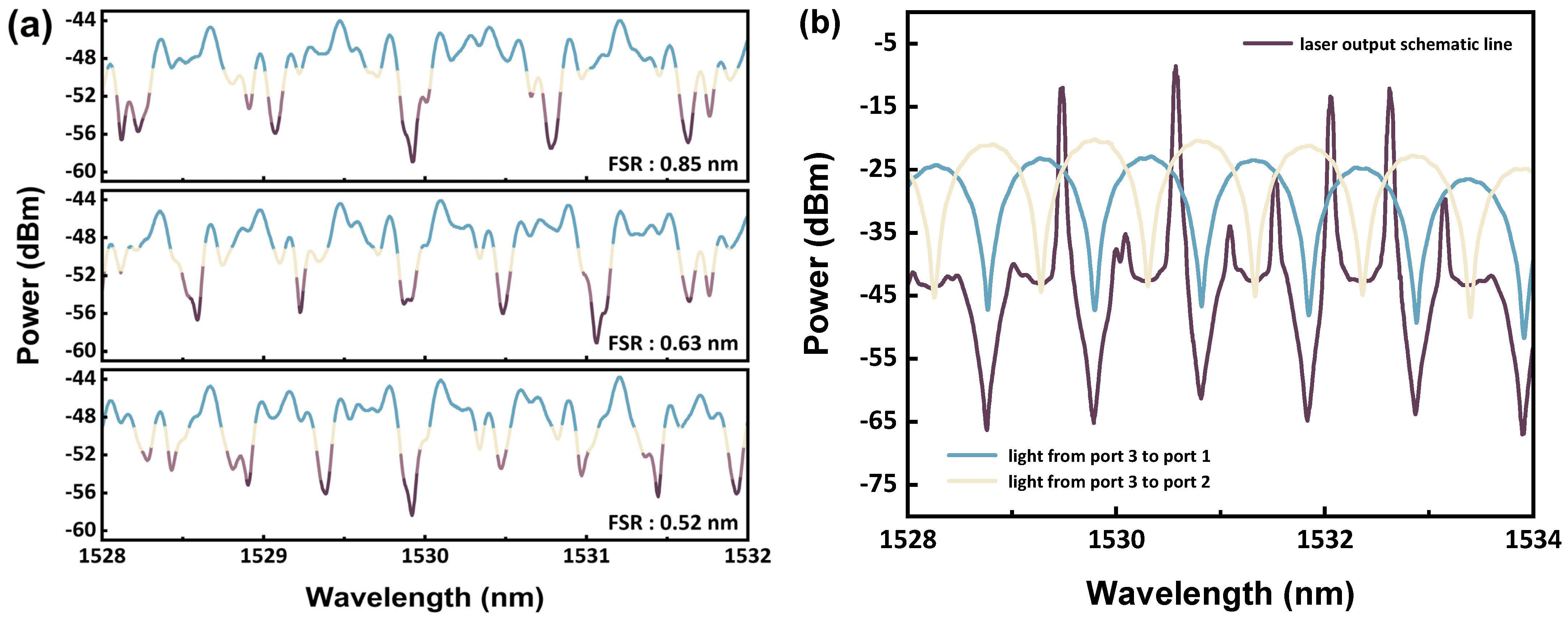
It is worth mentioning that when the beam passes through the BS inside the TDLI, multiple FP interferences will occur due to the reflection inside the BS [65,66], which forms some irregular interfering pattern embedded in the main interfering pattern at the output of the TDLI, and the spectrum is shown in Figure 2a. Since the reflected light inside the BS is relatively weak, the energy of the main interference needs to be weakened to observe the spectrum. The interferometric pattern of different FSRs shown in Figure 2a is observed from the incident light of EDFA entering the TDLI at port 1 and then reflected from the fiber connector at port 3 to the fiber connector at port 2 for OSA observation. It can be seen that the wavelengths of the peaks and troughs of the interference spectrum caused by the internal reflections of the BS are fixed regardless of the FSR of the main interference, although the powers of the peaks and troughs are modulated by the peaks and troughs of the main interference and have a difference in power. The yellow and blue lines in Figure 2b show the main interference spectra generated by the port 3 to port 2 and port 3 to port 1 paths of the TDLI, respectively. It can be seen that the intrinsic interference spectrum generated by the BS is no longer visible because its lower power has been overshadowed by the main interference with higher power. Nevertheless, the intrinsic interference generated by the BS still has an effect on the laser wavelength output, as will be shown in the subsequent experimental results. For the two complementary interference spectra depicted in Figure 2b, it is observed that the yellow line exhibits a higher interference power compared to the blue line. Additionally, the difference in power between the interference peak of the yellow line and the interference trough of the blue line is greater than that between the interference peak of the blue line and the interference trough of the yellow line. Consequently, the fiber ring laser structure in question displays a multi-wavelength laser spectrum, as indicated by the dark line in Figure 2b. Each lobe of interference is characterized by a pair of head horns. In addition, the lasing of the laser wavelength will be at the half-upper-waist of the lobe of the two main interferences, where the two main interferences are superimposed and have the highest power. The concept of “spatial hole-burning” as an effect of lasers is derived from [67,68]. The operating principle of hole-burning in a laser involves selectively depleting certain frequency components within the gain profile of the amplifying medium, creating a “hole” in the spectral line. This process is achieved by preferentially exciting atoms or molecules in the upper energy level of the laser transition, causing a reduction in the population of those specific energy states. As a result, the gain at those frequencies decreases, leading to a spectral “hole” where the gain is lower than the surrounding frequencies. Hole burning can be induced by various mechanisms, such as optical pumping, where external light sources excite the atoms to specific energy levels or have inhomogeneous broadening effects in the medium. The creation of these holes in the gain profile can have significant implications for the operation and performance of the laser, affecting parameters such as linewidth, power dependence, and mode pulling. Therefore, in this scheme, the hole will be formed in the gain spectrum corresponding to the node of the interference pattern according to inhomogeneous broadening, resulting in a decrease in the lasing threshold at the half-upper-waist of the lobe of the interference spectrum.

3. Experimental Results

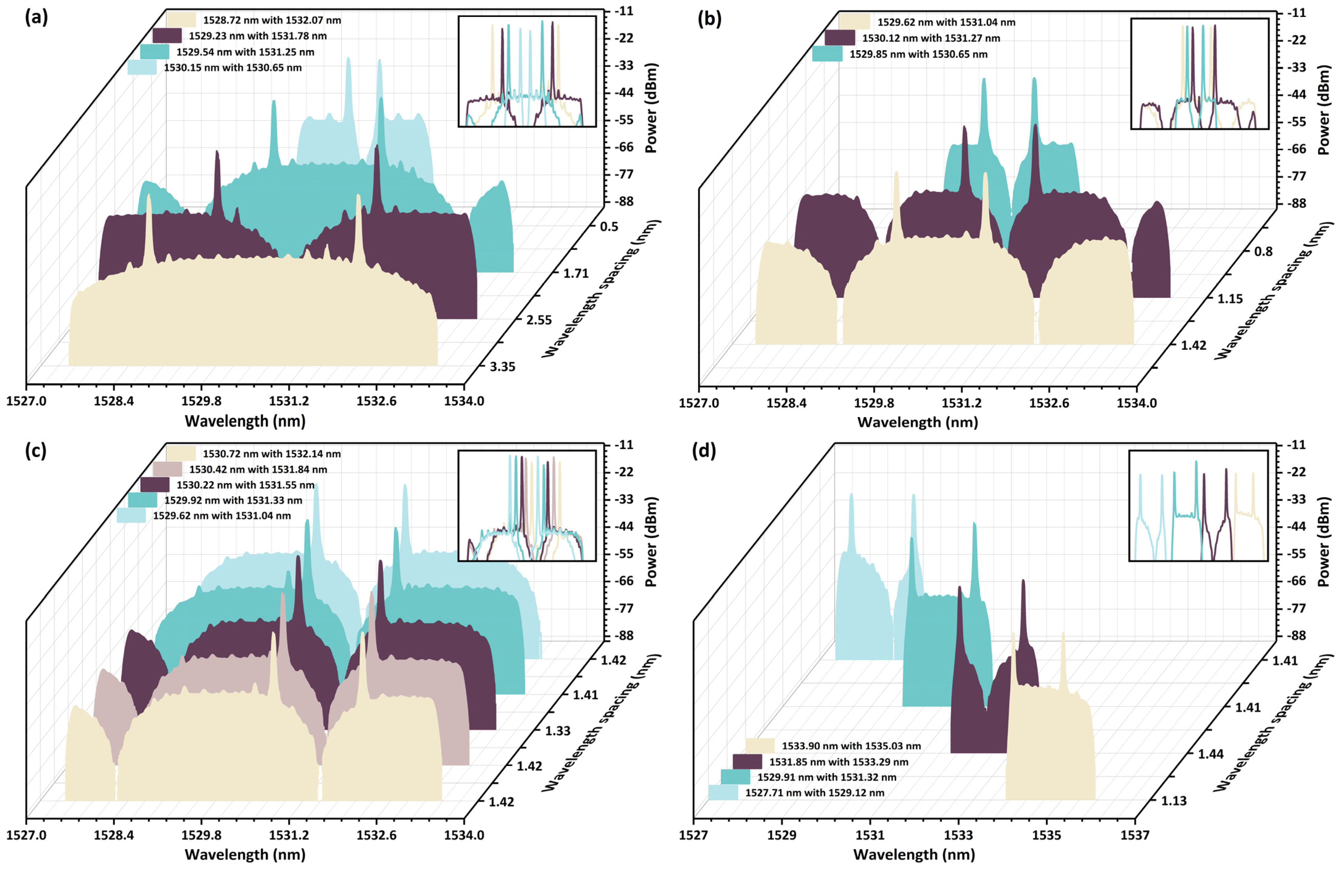
In this research, the FSR variation is achieved by adjusting the axial position of the prism through the movement of the micrometer head of the TDLI. The main function of the TBF is to filter out wavelengths other than 1527 nm to 1534 nm, and it is also used to ensure laser output by filtering a wider range of wavelengths when the laser wavelength spacing is small. Additionally, the power faults at the edges of the interferometric pattern indicate the areas where the TBF filters are applied. In addition, the OSA is set up with a spectral sampling range of 10 nm and 2001 points. Figure 3 shows various types of dual-wavelength lasers shaped by the Figure 1 architecture. Figure 3a shows the dual-wavelength laser with variable wavelength spacing by adjusting the interferometric pattern position and FSR size of the TDLI and filtering out the unnecessary wavelengths with the TBF. The wavelength spacing between the two wavelengths in the dual-wavelength laser varies from smallest to largest, which are 0.5 nm, 1.71 nm, 2.55 nm, and 3.35 nm. The wavelength positions of the dual-wavelength lasers are listed from smallest to largest wavelength spacing, which are 1530.15 nm and 1530.65 nm (light blue pattern); 1529.54 nm and 1531.25 nm (light green pattern); 1529.23 nm and 1531.78 nm (dark currant pattern); and 1528.72 nm and 1532.07 nm (yellow pattern), respectively. Moreover, the wavelength spacing variation of the dual-wavelength laser is adjusted according to the position of 1530.4 nm as the center, and the difference between the midpoint of the wavelength intervals of the dual-wavelength lasers from the smallest to the largest wavelength spacing and 1530.4 nm is 0 nm, 0.005 nm, 0.105 nm, and 0.005 nm, respectively. It can be noticed that no matter how the FSR varies, the wavelength position of the laser is always situated at the half-upper-waist of the lobe. It is also clear that the multiple interferences generated by the BS form a burr in the main interference pattern, which is caused by the amplification of the EDFA. It is also clear from the subfigure of Figure 3a that the wavelength positions of the dual-wavelength lasers with different spacings are highly overlapped with the peaks of the multiple interferences generated by the BS. This means that the sub-interferences generated by the BS deepen the spatial hole-burning effect, and the laser generation position is more likely to fall in the node of the half-upper-waist of the lobe, where it also overlaps with the peaks of the sub-interferences. As a result, the displacement between 1530.4 nm and the center point of the interval in a dual-wavelength laser with a wavelength spacing of 2.55 nm is larger. Figure 3b illustrates a dual-wavelength laser with staggered positions of several wavelengths. The laser configurations exhibit wavelength spacings of 0.8 nm, 1.15 nm, and 1.42 nm, with corresponding wavelength positions of 1529.85 nm and 1530.65 nm (light green pattern); 1530.12 nm and 1531.27 nm (dark currant pattern); and 1529.62 nm and 1531.04 nm (yellow pattern). It is noticeable that the midpoints of the wavelength intervals for the dual-wavelength lasers are distinct. This difference is attributed to the fact that the FSR of the TDLI can be adjusted arbitrarily to change the excitation points of the lasers, which should be close to the wave crests of the sub-interferences. The graph in Figure 3c depicts the regular tuning of the wavelength position of a dual-wavelength laser with almost all wavelength spacings of 1.42 nm. The shorter and longer wavelengths of the five dual-wavelength lasers are as follows: 1529.62 nm and 1531.04 nm (light blue pattern); 1529.92 nm and 1531.33 nm (light green pattern); 1530.22 nm and 1531.55 nm (dark currant pattern); 1530.42 nm and 1531.84 nm (light currant pattern); and 1530.72 nm and 1532.14 nm (yellow pattern), respectively. The difference in the positions of each pair of dual-wavelength lasers is approximately 0.3 nm. The position of the third pair of dual-wavelength lasers is slightly off due to the effects of sub-interference generated by the BS. It is worth noting that the dual-wavelength laser in the yellow spectrum of Figure 3b and the dual-wavelength laser in the light blue spectrum of Figure 3c have the same wavelength position and spacing, and their interference patterns are complementary. One is that the two lasers arise on the same lobe of the interference pattern, and the other is that the two lasers separately arise on the neighboring lobe of the interference pattern. This proves that the interference pattern position can be shifted; as long as the node of the interference pattern corresponds to the peak of the sub-interference, the same two dual-wavelength lasers can arise. Figure 3c illustrates a dual-wavelength laser featuring a narrow tuning range. To showcase a dual-wavelength laser with an extended tuning range, it is essential to fully utilize the TBF function to filter out unnecessary wavelengths and prevent mode competition. The outcomes, depicted in Figure 3d, demonstrate dual wavelengths and their respective spacings: 1527.71 nm and 1529.12 nm (light blue pattern), with a spacing of 1.41 nm; 1529.91 nm and 1531.32 nm (light green pattern), with a spacing of 1.41 nm; 1531.85 nm and 1533.29 nm (dark currant pattern), with a spacing of 1.44 nm; and 1533.9 nm and 1535.03 nm (yellow pattern), with a spacing of 1.13 nm. In the yellow part of the spectrum, the lasers have a smaller wavelength spacing because the power of EDFA is higher in the range of 1527 nm to 1534 nm. This makes it challenging for the laser to be stimulated at wavelengths beyond 1535 nm.
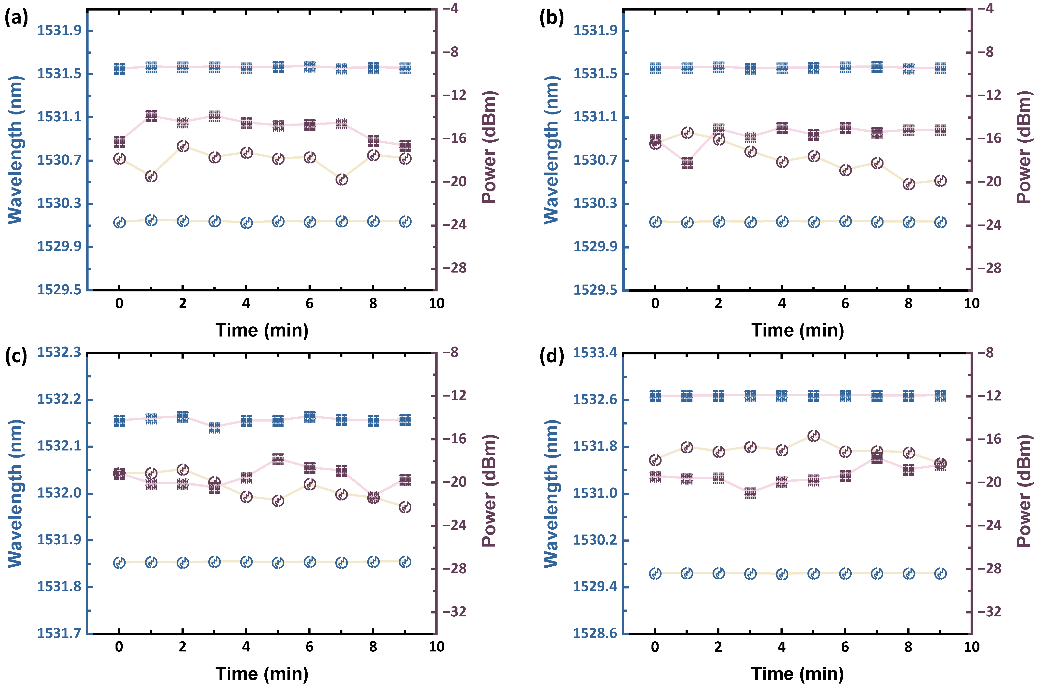
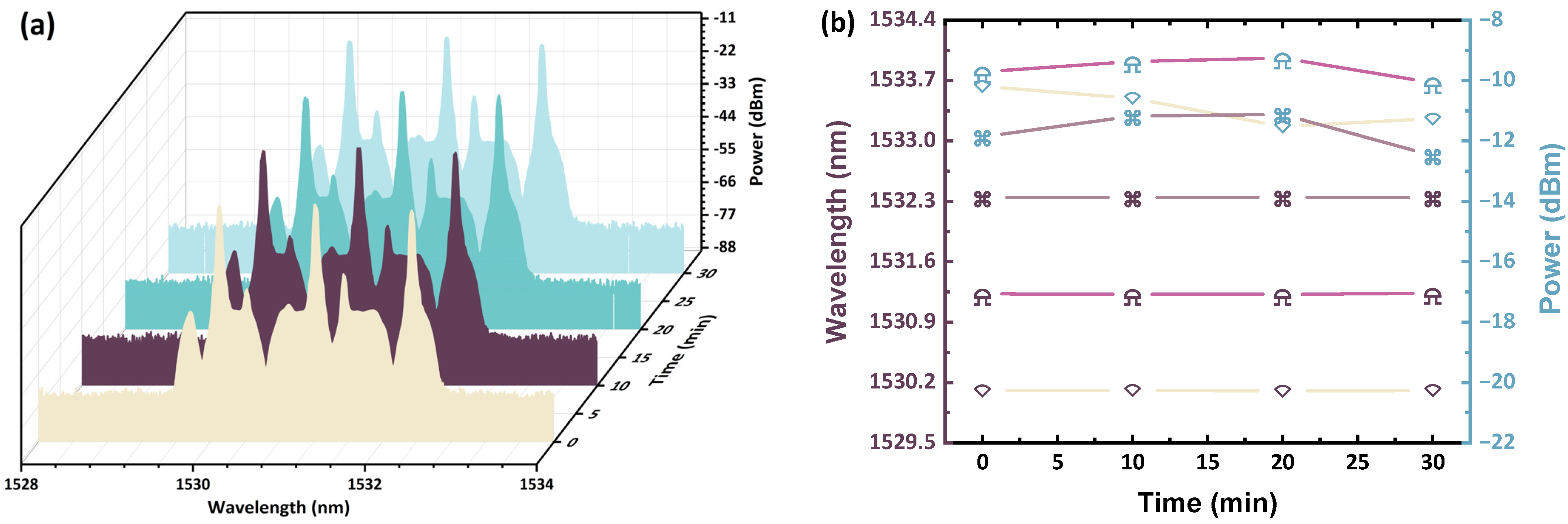
Figure 4 shows the case where the dual-wavelength laser position remains the same under different interferometric FSRs, and the laser spectrum at different times under this experimental scheme is verified to verify the stability of the system. The wavelengths of the dual-wavelength lasers in Figure 4a,b are both 1530.14 nm and 1531.56 nm, but the FSR of Figure 4a is 1.45 nm, while the FSR of Figure 4b is 0.9 nm. As mentioned in Figure 3, the same interference FSR, but with complementary phases, can produce the same dual-wavelength lasers. Here, the same dual-wavelength laser can be generated with different FSRs, and any point in the interference pattern cannot correspond to each other neatly. This serves as confirmation that the experimental setup is capable of generating multi-format lasers, indicating that the same laser wavelength can coexist with different interference states, a doing that has not been previously demonstrated in previous studies. Figure 5a shows the dual-wavelength laser case with the narrowest wavelength spacing, and Figure 5b shows the dual-wavelength laser case with several interfering lobes in the lasing wavelength gap. Additionally, the dual-wavelength laser states are recorded at different times to confirm their stability. Figure 5a shows a dual-wavelength laser with wavelengths of 1531.85 nm and 1532.15 nm at a wavelength spacing of 0.3 nm, which is achieved by filtering out unnecessary bands with TBF and setting the trough of the interferometric pattern between the two lasing wavelengths to maintain a balanced energy distribution. The dual-wavelength lasing involves wavelengths of 1529.65 nm and 1532.65 nm with a wavelength spacing of 3 nm, as shown in Figure 5b. There are eight nodes between the lasing wavelengths located at the half-upper-waist of the interference lobes. Despite this, it is noteworthy that the laser was not successfully excited at points on these eight nodes. The main reason for this is that the lasing wavelength aligns most accurately with the peak of the sub-interference, while the other eight nodes do not align as precisely with the peak of the sub-interference. Figure 6a–d illustrate the fluctuation of the wavelength position of the dual-wavelength laser in the cases of Figure 4a,b and Figure 5a,b and the change in the power value corresponding to the peak of the lasing wavelength every minute, respectively. In Figure 6, it is evident that each wavelength position of different dual-wavelength laser cases fluctuates by less than 0.1 nm. The maximum change in the value corresponding to the peak of each lasing wavelength exceeds 3 dB due to the lack of temperature control for the EDFA in this scheme. The temperature variation of the EDFA impacts its output spectrum [69] and consequently affects the stability of the lasing wavelength output in this fiber ring laser setup. Figure 7 shows the case of triple-wavelength lasers; Figure 7a shows their spectra recorded every 10 min; and Figure 7b shows their wavelength position fluctuations and power variations at different times. The triple-wavelength lasers emit light at 1530.1 nm, 1531.22 nm, and 1532.34 nm, with a consistent 1.12 nm spacing between wavelengths. The fluctuation of each wavelength of triple-wavelength lasers is consistently less than 0.1 nm every 10 min, and the power corresponding to the peak of the lasing wavelength does not change by more than 2 dB.
Maintaining a clear separation between telecommunication channels is essential to avoiding crosstalk. The wavelength separation of WDM in the C-band is usually 0.8 nm (100 GHz) or 0.4 nm (50 GHz). However, with the development of wavelength selective switch (WSS) components, it will be possible to support WDM with wavelength intervals less than 0.4 nm. WSS utilizes switch arrays that operate on wavelength-dispersed light to decouple or complex any single wavelength to a selected common or output port [70]. In a recent study [71], data communication in the C-band using two WDM channels at 0.3 nm intervals has been successfully demonstrated by WSS. Hence, this program can be effectively implemented in real-world scenarios. Furthermore, minimizing fiber loss, monitoring system temperature, monitoring laser output power, and adjusting the looped-in system’s power will be essential for maintaining stability in laser power output during practical applications. Moreover, the operations of TDLI and TBF can cover the 1520–1570 nm wavelength range. Consequently, it is theoretically feasible to use other bands of EDFA to amplify and produce lasers within the respective bands.

4. Conclusions

This study illustrates the utilization of erbium-doped fiber as a gain medium within a fiber ring architecture to establish a laser system with a principal lasing wavelength of approximately 1531 nm, coinciding with the amplification band of an EDFA. The TDLI serves a primary role in facilitating the generation of multi-format and multi-wavelength lasers through the superposition of two interferences with a 180-degree phase difference, thereby disrupting the homogeneous broadening effect of EDFA. Additionally, the TBF is deployed to eliminate extraneous spectral components, mitigating mode competition. The lasing wavelength assumes a position at the confluence of two complementary interference superposition patterns stemming from spatial hole-burning effects. Crucially, this lasing wavelength must correspond with the peaks of the FP interferences engendered by the BS within the TDLI. Hence, the presentation of highly adjustable FSR by TDLI allows interference standing wave patterns to be interchanged in real-time, supplementing the TBF to effectuate controlled variations in wavelength spacing and position in the multi-wavelength laser. As a consequence, this approach enables the deliberate orchestration of regular or irregular changes in the multi-wavelength laser, fostering the creation of multi-format, multi-wavelength lasers characterized by different interference states but a consistent wavelength position.

Author Contributions

Conceptualization, C.-K.Y. and P.-C.P.; methodology, C.-K.Y.; data curation, C.-K.Y.; model validation, C.-K.Y.; formal analysis, C.-K.Y., A.M.D. and P.-C.P.; investigation, C.-K.Y., A.M.D. and P.-C.P.; visualization: C.-K.Y.; writing—original draft preparation: C.-K.Y.; writing—review and editing: C.-K.Y., A.M.D. and P.-C.P. All authors have read and agreed to the published version of the manuscript.

Funding

This work was supported by the National Science and Technology Council, Taiwan, under Grant NSTC 112-2221-E-027-076-MY2.

Institutional Review Board Statement

Not applicable.

Informed Consent Statement

Not applicable.

Data Availability Statement

The original contributions presented in the study are included in the article, further inquiries can be directed to the corresponding author.

Conflicts of Interest

The authors declare no conflicts of interest.

References

  1. Nemova, G. Brief Review of Recent Developments in Fiber Lasers. Appl. Sci. 2024, 14, 2323. [Google Scholar] [CrossRef]
  2. Churkin, D.V.; Sugavanam, S.; Vatnik, I.D.; Wang, Z.; Podivilov, E.V.; Babin, S.A.; Rao, Y.J.; Turitsyn, S.K. Recent advances in fundamentals and applications of random fiber lasers. Adv. Opt. Photon. 2015, 7, 516–569. [Google Scholar] [CrossRef]
  3. Shi, W.; Fang, Q.; Zhu, X.; Norwood, R.A.; Peyghambarian, N. Fiber lasers and their applications. Appl. Opt. 2014, 53, 6554–6568. [Google Scholar] [CrossRef]
  4. Addanki, S.; Amiri, I.S.; Yupapin, P. Review of optical fibers-introduction and applications in fiber lasers. Results Phys. 2018, 10, 743–750. [Google Scholar] [CrossRef]
  5. Kim, T.H. Analysis of optical communications, fiber optics, sensors and laser applications. J. Mach. Comput. 2023, 3, 115–125. [Google Scholar] [CrossRef]
  6. Lu, H.H.; Huang, X.H.; Li, C.Y.; Xu, Y.Z.; Jin, J.L.; Chen, W.X.; Lin, C.H.; Wu, T.M. Two-way free-space optics-based interface between fibre and 5G communication employing polarisation-orthogonal modulation. Commun. Eng. 2023, 2, 89. [Google Scholar] [CrossRef]
  7. Dehnaw, A.M.; Manie, Y.C.; Du, L.Y.; Yao, C.K.; Li, Y.L.; Hayle, S.T.; Peng, P.C. Bidirectional Free Space Optics Communication for Long-Distance Sensor System. J. Lightw. Technol. 2023, 41, 5870–5878. [Google Scholar] [CrossRef]
  8. Peng, P.C.; Jhang, J.J.; Peng, Y.W.; Bitew, M.A.; Chi, Y.C.; Wu, W.C.; Wang, H.Y.; Lin, G.R.; Li, C.Y.; Lu, H.H. Tunable C-and L-band laser source based on colorless laser diode. Laser Phys. Lett. 2017, 14, 035806. [Google Scholar] [CrossRef]
  9. Manie, Y.C.; Yao, C.K.; Yeh, T.Y.; Teng, Y.C.; Peng, P.C. Laser-based optical wireless communications for internet of things (IoT) application. IEEE Internet Things J. 2022, 9, 24466–24476. [Google Scholar] [CrossRef]
  10. Dehnaw, A.M.; Shiu, R.K.; Chen, R.B.; Li, J.W.; Manie, Y.C.; Liang, H.C.; Peng, P.C. Self-start multi-wavelength laser source with tunable delay-line interferometer and optical fiber reflector for wireless communication system. Appl. Sci. 2021, 11, 9553. [Google Scholar] [CrossRef]
  11. Murray, J.B.; Cerjan, A.; Redding, B. Distributed Brillouin fiber laser sensor. Optica 2022, 9, 80–87. [Google Scholar] [CrossRef]
  12. Yao, C.K.; Manie, Y.C.; Chen, H.M.; Hsu, W.Y.; Lin, T.C.; Peng, P.C. Involvement of free-space optics in Raman distributed temperature sensing. Opt. Lett. 2023, 48, 6340–6343. [Google Scholar] [CrossRef]
  13. Jati, M.P.; Luthfi, M.I.; Yao, C.K.; Dehnaw, A.M.; Manie, Y.C.; Peng, P.C. An Extremely Close Vibration Frequency Signal Recognition Using Deep Neural Networks. Appl. Sci. 2024, 14, 2855. [Google Scholar] [CrossRef]
  14. Soares, L.; Perez-Herrera, R.A.; Novais, S.; Ferreira, A.; Frazão, O.; Silva, S. Paracetamol concentration-sensing scheme based on a linear cavity fiber laser configuration. Opt. Fiber Technol. 2023, 80, 103407. [Google Scholar] [CrossRef]
  15. Soares, L.; Pérez-Herrera, R.A.; Novais, S.; Ferreira, A.; Silva, S.; Frazão, O. Linear Fiber Laser Configurations for Optical Concentration Sensing in Liquid Solutions. Photonics 2024, 11, 393. [Google Scholar] [CrossRef]
  16. Nemova, G.; Jin, X.; Chen, L.R.; Firstov, S.V.; Sezerman, O. Modeling and experimental characterization of a dual-wavelength Bi-doped fiber laser with cascaded cavities. J. Opt. Soc. Am. B 2020, 37, 1453–1460. [Google Scholar] [CrossRef]
  17. Nemova, G.; Kashyap, R. Yb3+-doped fiber laser with integrated optical cooler. In Proceedings of the Laser Technology for Defense and Security VI, Orlando, FL, USA, 5–6 April 2010; SPIE: Bellingham, WA, USA, 2015; Volume 7686, pp. 241–247. [Google Scholar]
  18. Tokita, S.; Murakami, M.; Shimizu, S.; Hashida, M.; Sakabe, S. Liquid-cooled 24 W mid-infrared Er: ZBLAN fiber laser. Opt. Lett. 2009, 34, 3062–3064. [Google Scholar] [CrossRef]
  19. Topper, B.; Peysokhan, M.; Albrecht, A.R.; Flores, A.S.; Kuhn, S.; Hässner, D.; Hein, S.; Hupel, C.; Nold, J.; Haarlammert, N.; et al. Laser cooling of a Yb doped silica fiber by 18 Kelvin from room temperature. Opt. Lett. 2021, 46, 5707–5710. [Google Scholar] [CrossRef]
  20. Nishizawa, N. Ultrashort pulse fiber lasers and their applications. Jpn. J. Appl. Phys. 2014, 53, 090101. [Google Scholar] [CrossRef]
  21. Zhang, L.; Tian, Z.; Chen, N.K.; Grattan, K.T.; Yao, Y.; Rahman, B.A.; Li, X.H.; Yao, C.K.; Han, H.L.; Chui, H.C.; et al. Pulse Dynamics of an All-Normal-Dispersion Ring Fiber Laser Under Four Different Pulse Regimes. IEEE Access 2020, 8, 115263–115272. [Google Scholar] [CrossRef]
  22. Chen, N.K.; Lin, J.W.; Liu, F.Z.; Liaw, S.K. Wavelength-Tunable Er3+-Doped fs Mode-Locked Fiber Laser Using Short-Pass Edge Filters. IEEE Photon. Technol. Lett. 2010, 22, 700–702. [Google Scholar] [CrossRef]
  23. Chen, N.K.; Liu, F.Z.; Chuang, H.P.; Lai, Y.; Yang, S.D.; Lin, J.W.; Liaw, S.K.; Chang, Y.C.; Huang, C.B.; Chi, S. Highly efficient femtosecond pulse stretching by tailoring cavity dispersion in erbium fiber lasers with an intracavity short-pass edge filter. Opt. Express 2011, 19, 15879–15884. [Google Scholar] [CrossRef] [PubMed]
  24. Han, H.; Chen, N.K.; Zhang, L.; Xie, Y.; Tian, Z.; Yao, Y.; Huang, Y.; Zhang, X. Output pulse characteristics of a Mamyshev fiber oscillator. Photonics 2021, 8, 590. [Google Scholar] [CrossRef]
  25. Yeh, C.H.; Liu, L.H.; Ko, H.S.; Wang, B.Y.; Hsu, W.H.; Chow, C.W.; Chen, J.H. Quad-ring based erbium fiber laser for switchable and stable single-longitudinal-mode operation. Opt. Fiber Technol. 2021, 61, 102450. [Google Scholar] [CrossRef]
  26. Li, G.H.; Lin, Y.Z.; Chang, H.W.; Yeh, C.H.; Chen, J.R.; Wang, B.Y.; Hsu, W.H.; Chow, C.W.; Liaw, S.K. Stabilized single-longitudinal-mode fiber laser with broadband and flat wavelength output. Phys. Scr. 2020, 96, 015503. [Google Scholar] [CrossRef]
  27. Yamashita, S.; Takubo, Y. Wide and fast wavelength-swept fiber lasers based on dispersion tuning and their application to optical coherence tomography. Photon. Sens. 2013, 3, 320–331. [Google Scholar] [CrossRef]
  28. Jiang, H.; Zhao, Z.; Jin, L.; Set, S.Y.; Yamashita, S. Self-wavelength-sweeping in a bi-directional thulium-doped fiber ring laser. Appl. Phys. Express 2019, 12, 042006. [Google Scholar] [CrossRef]
  29. Chen, H.; Jiang, X.; Xu, S.; Zhang, H. Recent progress in multi-wavelength fiber lasers: Principles, status, and challenges. Chin. Opt. Lett. 2020, 18, 041405. [Google Scholar] [CrossRef]
  30. Kbashi, H.J.; Sharma, V.; Sergeyev, S.V. Tunable Multiwavelength SOA-Based Fiber Laser. Electronics 2023, 12, 3277. [Google Scholar] [CrossRef]
  31. Imbu, J.J.; Bitew, M.A.; Chang, C.H.; Tang, W.C.; Manie, Y.C.; Peng, P.C. Multi-wavelength generation? Based on RSOA for passive optical networks. In Proceedings of the 2017 IEEE International Conference on Consumer Electronics-Taiwan (ICCE-TW), Taipei, Taiwan, 12–14 June 2017. [Google Scholar]
  32. Peng, P.C.; Tseng, H.Y.; Chi, S. Long-distance FBG sensor system using a linear-cavity fiber Raman laser scheme. IEEE Photonics Technol. Lett. 2004, 16, 575–577. [Google Scholar] [CrossRef]
  33. Awsaj, M.K.; Al-Mashhadani, T.F.; Al-Mashhadani, M.K.S.; Hammudi, R.N.; Ali, A.Y.; Zan, M.S.D.; Arsad, N. Tunable 60 GHz Multiwavelength Brillouin Erbium Fiber Laser. Appl. Sci. 2023, 13, 3275. [Google Scholar] [CrossRef]
  34. Wang, T.; Yang, A.; Shi, F.; Huang, Y.; Wen, J.; Zeng, X. High-order mode lasing in all-FMF laser cavities. Photon. Res. 2019, 7, 42–49. [Google Scholar] [CrossRef]
  35. Radzi, N.M.; Latif, A.A.; Ismail, M.F.; Liew, J.Y.; Awang, N.A.; Lee, H.K.; Ahmad, F.; Norizan, S.F.; Ahmad, H. Tunable spacing dual-wavelength Q-switched fiber laser based on tunable FBG device. Photonics 2021, 8, 524. [Google Scholar] [CrossRef]
  36. Gao, M.; Yin, B.; Lv, Y.; Sang, G.; Hou, B.; Li, H.; Wang, M.; Wu, S. Tunable and switchable dual-wavelength SLM Narrow-linewidth fiber laser with a PMFBG-FP filter cascaded by multi-ring cavity. Photonics 2022, 9, 756. [Google Scholar] [CrossRef]
  37. He, W.; Li, D.; Zhu, L.; Dong, M.; Luo, F. Tunable multiwavelength erbium-doped fiber laser employing PM-FBG and Mach–Zehnder interferometer with optical fiber delay line. IEEE Photon. J. 2017, 9, 7202108. [Google Scholar] [CrossRef]
  38. Zhou, X.; Li, Z.; Zhou, Y. Tunable and switchable multi-wavelength fiber laser based on polarization hole burning effect and Sagnac loop mirrors. Opt. Quantum Electron. 2020, 52, 451. [Google Scholar] [CrossRef]
  39. Ahmad, H.; Jasim, A.A. Stable C-band fiber laser with switchable multi-wavelength output using coupled microfiber Mach-Zehnder interferometer. Opt. Fiber Technol. 2017, 36, 105–114. [Google Scholar] [CrossRef]
  40. Martinez-Ramirez, L.G.; Alvarado, E.S.; Gallegos-Arellano, E.; Fernandez-Jaramillo, A.A.; Estudillo-Ayala, J.M.; Jauregui-Vazquez, D.; Rojas-Laguna, R.; Sierra-Hernandez, J.M. Select-cutoff Mach-Zehnder interferometer based on waist-enlarged technique and its multi-wavelength fiber laser application. Infrared Phys. Technol. 2023, 128, 104508. [Google Scholar] [CrossRef]
  41. Lopez-Dieguez, Y.; Estudillo-Ayala, J.M.; Jauregui-Vazquez, D.; Herrera-Piad, L.A.; Sierra-Hernandez, J.M.; Garcia-Mina, D.F.; Gallegos-Arellano, E.; Hernandez-Garcia, J.C.; Rojas-Laguna, R. Erbium ring fiber laser cavity based on tip modal interferometer and its tunable multi-wavelength response for refractive index and temperature. Appl. Sci. 2018, 8, 1337. [Google Scholar] [CrossRef]
  42. Tian, Z.; Chen, N.K.; Shum, P.P.; Yao, C.K.; Zhang, L.; Yao, Y.; Grattan, K.T.V.; Ren, S.; Wu, Q. Erbium-doped dual wavelength fiber laser interferometric proximity sensor with ±16 nm measurement accuracy. In Proceedings of the CLEO: QELS_Fundamental Science, San Jose, CA, USA, 9–14 May 2021; Optica Publishing Group: Washington, DC, USA, 2021. [Google Scholar]
  43. Geng, X.; Jiang, Y.; Gu, H.; Luo, S.; Sun, M.; Li, L. Switchable multi-wavelength fiber lasers based on asymmetric biconical fiber tapers. Opt. Commun. 2023, 548, 129837. [Google Scholar] [CrossRef]
  44. Torres-Torres, M.; Salceda-Delgado, G.; Rodríguez-Carreón, V.C.; Martinez-Rios, A.; Sierra-Hernandez, J.M.; Antonio-Lopez, J.E.; Amezcua-Correa, R.; Estudillo-Ayala, J. Reshaping the output of fiber lasers by using a variable intra-cavity filter based on a reconfigurable Fabry–Perot interferometer. Laser Phys. 2021, 31, 035102. [Google Scholar] [CrossRef]
  45. Chang, Y.; Pei, L.; Ning, T.; Zheng, J. Switchable multi-wavelength fiber laser based on hybrid structure optical fiber filter. Opt. Laser Technol. 2020, 124, 105985. [Google Scholar] [CrossRef]
  46. Tang, Z.; Lou, S.; Wang, X. Stable and widely tunable single-/dual-wavelength erbium-doped fiber laser by cascading a twin-core photonic crystal fiber based filter with Mach-Zehnder interferometer. Opt. Laser Technol. 2019, 109, 249–255. [Google Scholar] [CrossRef]
  47. Filoteo-Razo, J.D.; Hernandez-Garcia, J.C.; Estudillo-Ayala, J.M.; Pottiez, O.; Jauregui-Vazquez, D.; Sierra-Hernandez, J.M.; Lauterio-Cruz, J.P.; Carrillo-Delgado, C.M.; Rojas-Laguna, R. Multi-wavelength Er–Yb-doped fibre ring laser using a double-pass Mach–Zehnder interferometer with a Sagnac interferometer. Opt. Laser Technol. 2021, 139, 106994. [Google Scholar] [CrossRef]
  48. Chang, Y.; Pei, L.; Ning, T.; Zheng, J.; Li, J.; Xie, C. Switchable and tunable multi-wavelength fiber ring laser employing a cascaded fiber filter. Opt. Fiber Technol. 2020, 58, 102240. [Google Scholar] [CrossRef]
  49. Huang, B.; Sheng, X.; Tang, Z.; Lou, S. High SMSR and widely tunable multi-wavelength erbium doped fiber laser based on cascaded filters. Infrared Phys. Technol. 2022, 122, 104082. [Google Scholar] [CrossRef]
  50. Yao, C.K.; Lee, M.C.; Peng, P.C. EDFA-Based Multi-Wavelength Laser Using Tunable Filter and Delay-Interferometer for WDM Systems. In Proceedings of the 2022 IEEE International Conference on Consumer Electronics-Taiwan (ICCE-TW), Beitou, Taipei, Taiwan, 6–8 July 2022. [Google Scholar]
  51. Fan, B.; Zhou, X.; Li, Z.; Zhou, Y.; Wang, T. Experimental research on an L-band multi-wavelength erbium-doped fiber laser based on a cascaded Sagnac loop and M–Z filters. Laser Phys. 2019, 29, 065102. [Google Scholar] [CrossRef]
  52. He, W.; Yuan, H.; Lou, X.; Zhu, L.; Dong, M. Multi-wavelength switchable erbium-doped fiber laser based on a hybrid filter incorporating a bi-tapered Mach–Zehnder interferometer and Sagnac loop. Phys. Scr. 2019, 94, 125502. [Google Scholar] [CrossRef]
  53. Zhou, X.; Ni, Y.; Wei, Y. L-Band multi-wavelength erbium-doped fibre laser based on non-linear optical loop mirror and dual-channel Mach–Zehnder interferometer. J. Mod. Opt. 2017, 64, 210–213. [Google Scholar] [CrossRef]
  54. Herrera-Piad, L.A.; Marrujo-García, S.; Hernández-Romano, I.; May-Arrioja, D.A.; Minkovich, V.P.; Torres-Cisneros, M. Highly Stable Switchable Emissions of an Erbium-Doped Fiber Ring Laser Using Cascaded MZIs Based on CHCF. Machines 2022, 10, 962. [Google Scholar] [CrossRef]
  55. Tian, X.; Zhang, L.; Yao, Y.; Xu, H.; Zhu, K.; Zhang, X.; Nie, Z. Interval Adjustable Dual-Wavelength Erbium-Doped Fiber Laser Based on Cascaded Two Mach-Zehnder Interferometers. Photonics 2023, 10, 1156. [Google Scholar] [CrossRef]
  56. Zhang, L.; Tian, Z.; Chen, N.K.; Han, H.; Liu, C.N.; Grattan, K.T.; Rahman, B.M.A.; Zhou, H.; Liaw, S.K.; Bai, C. Room-temperature power-stabilized narrow-linewidth tunable erbium-doped fiber ring laser based on cascaded Mach-Zehnder interferometers with different free spectral range for strain sensing. J. Light. Technol. 2020, 38, 1966–1974. [Google Scholar] [CrossRef]
  57. Peng, Y.; Peng, J.; Pan, H.; Zhang, A.; Liu, Z.; Chen, Z.; Zhang, B.; Liu, X.; Cao, C.; Du, P. Switchable multi-wavelength actively Q-switched erbium-doped fiber laser based on nonlinear polarization rotation and Sagnac filter. Optik 2023, 284, 170955. [Google Scholar] [CrossRef]
  58. Al-Rubaiyee, H.A.; Al-Hayali, S.K.; Harun, S.W.; Al-Janabi, A.H. Vernier effect based on cascading two Mach–Zehnder interferometers for selectable comb filter and saturable absorber applications in erbium-doped fiber laser. Opt. Fiber Technol. 2024, 84, 103757. [Google Scholar] [CrossRef]
  59. Al-Rubaiyee, H.A.; Al-Hayali, S.K.; Al-Janabi, A.H. Vernier effect based on hybrid fiber interferometers: A new tool for wavelength switchability and adjustable free spectral range fiber lasing. Opt. Contin. 2023, 2, 1203–1215. [Google Scholar] [CrossRef]
  60. Yin, G.; Lou, S.; Wang, X.; Han, B. Tunable multi-wavelength erbium-doped fiber laser by cascading a standard Mach–Zehnder interferometer and a twin-core fiber-based filter. Laser Phys. Lett. 2013, 10, 125110. [Google Scholar] [CrossRef]
  61. Jachpure, D.; Vijaya, R. Mixed line broadening in the saturable absorption of erbium-doped fiber. Opt. Quantum Electron. 2023, 55, 113. [Google Scholar] [CrossRef]
  62. Yamashita, S.; Hotate, K.J.E.L. Multiwavelength erbium-doped fibre laser using intracavity etalon and cooled by liquid nitrogen. Electron. Lett. 1996, 32, 1298–1299. [Google Scholar] [CrossRef]
  63. Park, N.; Wysocki, P.F. 24-line multiwavelength operation of erbium-doped fiber-ring laser. IEEE Photon. Technol. Lett. 1996, 8, 1459–1461. [Google Scholar] [CrossRef]
  64. Dejband, E.; Yao, C.K.; Manie, Y.C.; Huang, P.Y.; Lee, H.K.; Tan, T.H.; Peng, P.C. Utilizing a Tunable Delay Line Interferometer to Improve the Sensing Accuracy of an FBG Sensor System. Photonics 2022, 9, 11. [Google Scholar] [CrossRef]
  65. Hénault, F. Quantum physics and the beam splitter mystery. In Proceedings of the Nature of Light: What are Photons? VI, San Diego, CA, USA, 10–13 August 2015; SPIE: Bellingham, WA, USA, 2015; Volume 9570, pp. 199–213. [Google Scholar]
  66. Yang, X.; Kweun, J.M.; Kim, Y.Y. Theory for perfect transmodal Fabry-Perot interferometer. Sci. Rep. 2018, 8, 69. [Google Scholar] [CrossRef] [PubMed]
  67. Bennett, W.R., Jr. Hole burning effects in a He-Ne optical maser. Phys. Rev. 1962, 126, 580. [Google Scholar] [CrossRef]
  68. Haken, H.; Sauermann, H. Frequency shifts of laser modes in solid state and gaseous systems. Z. Für Phys. 1963, 176, 47–62. [Google Scholar] [CrossRef]
  69. Bebawi, J.A.; Kandas, I.; El-Osairy, M.A.; Aly, M.H. A comprehensive study on EDFA characteristics: Temperature impact. Appl. Sci. 2018, 8, 1640. [Google Scholar] [CrossRef]
  70. Ma, Y.; Stewart, L.; Armstrong, J.; Clarke, I.G.; Baxter, G. Recent progress of wavelength selective switch. J. Lightw. Technol. 2020, 39, 896–903. [Google Scholar] [CrossRef]
  71. Zhang, Y.; He, Z.; Wu, Z.; Ren, J.; Liu, B.; Lei, T.; Yuan, X. Ultrabroadband 2D-Dispersive Wavelength Selective Switch with 1.57 GHz Hyperfine Spectral Resolution and >1600 Channels. Laser Photon. Rev. 2023, 17, 2300232. [Google Scholar] [CrossRef]
Figure 1. An experimental framework involves a multi-wavelength erbium-doped fiber ring laser with a delayed line interferometer (internal structure enlargement) as the primary component. (TDLI: tunable delay line interferometer; EDFA: erbium-doped fiber amplifier; TBF: tunable bandpass filter; OSA: optical spectral analyzer).
Applsci 14 06933 g001
Figure 2. (a) The spectrum shows multiple FP interferences resulting from the combination of two BS and the primary interference caused by TDLI with different FSRs by virtue of reflections from the end face of the fiber head. The EDFA emits light from port 1 into the TDLI, which is then reflected by port 3 and the BS into port 2 for observation by the OSA. (b) Transmission spectra of two-phase complementary interferences formed by TDLI and spectral characteristics of a multi-wavelength laser capable of output in the Figure 1 framework. The EDFA emits light, which passes from ports 3 to 2 and 1, respectively, and then yellow and blue line interferograms can be obtained with the OSA, respectively.
Applsci 14 06933 g002
Figure 3. (a) Dual-wavelength laser with variable spacing and consistent center position of dual wavelengths. (b) Dual-wavelength laser with intertwined wavelength positions. (c,d) Dual-wav-length laser with regular positional tuning and similar wavelength spacing (the subplot is a superimposed drawing of the spectrum that does not correspond to the power scale of the vertical axis).
Applsci 14 06933 g003
Figure 4. (a,b) The same dual-wavelength laser with different interferences and the spectral observation at different times.
Applsci 14 06933 g004
Figure 5. (a) Dual-wavelength laser with the narrowest wavelength spacing. (b) Dual-wavelength laser with several interfering lobes between the lasing wavelengths.
Applsci 14 06933 g005
Figure 6. (a,b) The wavelength position and the power corresponding to the peak of the lasing wavelength per minute are obtained from Figure 4a,b, respectively. (c,d) The wavelength position and the power corresponding to the peak of the lasing wavelength per minute are obtained from Figure 5a,b, respectively. (The yellow lines with circle signs represent the shorter wavelength; the pink lines with square signs represent the longer wavelength; the blue signs correspond to wavelength positions; and the dark signs correspond to power values).
Applsci 14 06933 g006
Figure 7. (a) A record of triple-wavelength lasers with the same wavelength spacing every ten minutes. (b) The wavelength position and the power corresponding to the peak of the lasing wavelength per ten minutes are obtained from (a). (The yellow line is at 1530.1 nm, the bright red line is at 1531.22 nm, and the coffee line is at 1532.34 nm; the dark signs correspond to wavelength positions, and the blue signs correspond to power values).
Applsci 14 06933 g007
Disclaimer/Publisher’s Note: The statements, opinions and data contained in all publications are solely those of the individual author(s) and contributor(s) and not of MDPI and/or the editor(s). MDPI and/or the editor(s) disclaim responsibility for any injury to people or property resulting from any ideas, methods, instructions or products referred to in the content.