Article

Experimental Study on the Water Absorption, Compaction Effect, and Pull-Out Bearing Characteristics of Water-Absorbing and Compaction Anchoring Bolts

1
School of Civil Engineering, Lanzhou University of Technology, Lanzhou 730050, China
2
School of Railway Technology, Lanzhou Jiaotong University, Lanzhou 730030, China
3
School of Science, Lanzhou University of Technology, Lanzhou 730050, China
*
Author to whom correspondence should be addressed.
Appl. Sci. 2024, 14(16), 6960; https://doi.org/10.3390/app14166960
Submission received: 7 July 2024 / Revised: 5 August 2024 / Accepted: 6 August 2024 / Published: 8 August 2024

Abstract

:
In response to a series of engineering disasters encountered during the excavation and support construction of loess tunnels, considering the issues of water enrichment in surrounding rock induced by excavation disturbance and system bolt failure, drawing on the concepts of lime pile composite foundation and composite bearing arch, and based on the principle of the New Austrian Tunneling Method (NATM) that fully mobilizes and leverages the self-supporting capacity of surrounding rock, this study comprehensively considers the wetting and stress adjustment processes of the surrounding rock after excavation disturbance in loess tunnels. By adopting the technical principle of “water absorption and densification of shallow surrounding rock, suspension and anchoring of deep surrounding rock, and composite arch bearing”, a new type of water-absorbing, densifying, and anchoring bolt was developed that can reduce the water content of surrounding rock while enhancing its resistance. To further investigate the water absorption, densification effect, and pull-out bearing characteristics of this new bolt, laboratory model tests were conducted, examining the temperature, pore water pressure, densification stress of the soil around the bolt, as well as the physical properties of the soil in the consolidation zone. The test results indicate that a cylindrical heat source forms around the water-absorbing, densifying, and anchoring bolt, significantly inducing the thermal consolidation of the surrounding soil. The variations in temperature, pore water pressure, and densification stress of the soil around the bolt truly reflect the qualitative patterns of hydro-thermal–mechanical changes during the water absorption, curing, and exothermic reaction processes. The water absorption and densification segment of the bolt effectively enhances the density of the soil in the water absorption, densification, and consolidation zone, improving soil strength parameters. Compared to traditional mortar-bonded bolts, the water-absorbing, densifying, and anchoring bolt exhibits a greater pull-out bearing capacity. The research findings provide important guidance for the theoretical design and engineering application of this new type of bolt.

1. Introduction

With the large-scale construction of infrastructure such as high-speed railways, highways, and water conveyance tunnels in the western region of China, tunnel projects in the gullied and ridge-hilly areas of the Loess Plateau face numerous challenges. The unique structural and water-sensitive characteristics of loess often lead to engineering disasters during tunnel construction, including surface subsidence, large deformations of the surrounding rock, sudden water inrushes, mud flows, lining cracks, and water leakage [1,2,3]. These pose significant safety challenges to tunnel construction in water-rich loess geological conditions. In response to the series of engineering problems faced during the construction and operation of loess tunnels, many researchers have conducted systematic research and analysis from aspects such as the causes of the problems, disaster mechanisms, prevention measures, and more. X L Zhang [4] used the surrounding rock grade, groundwater conditions, burial depth, excavation method, and support closure time as risk factors. Through the deep mining of the existing case data, he established a collapse analysis and prediction model for loess tunnels. This model predicts and analyzes the impact of various risk factors on the construction of loess tunnels. Based on mathematical theory, Z G Xu [5] established a model for identifying and analyzing the risk of collapse in loess tunnels. This model examines and analyzes the impact weights of multiple factors such as the surrounding rock lithology, terrain, excavation span, burial depth, groundwater, rainfall, construction technology, and management level on the risk of collapse in loess tunnels. It provides a new method for evaluating the risk of collapse during the construction of loess tunnels. Based on the existing research findings, W Sun [6] conducted a systematic analysis of 27 typical loess tunnels in loess regions. They proposed that the main types of water-rich loess surrounding rock are naturally water-rich, excavation-induced water enrichment, and surface rainfall infiltration-induced water enrichment. They elaborated on the formation mechanism and seepage characteristics of water-rich surrounding rock, providing valuable references for the theoretical research, design, and construction of loess tunnel projects. Q Y Hong [7] conducted research and analysis on the impact of spatial distribution changes in soft plastic loess on large-section high-speed railway tunnels through on-site monitoring and measurement. The results indicate that different spatial positions of the soft plastic loess layer relative to the tunnel will lead to different mechanical behaviors during tunnel construction. S Shao [8] comprehensively considered factors such as loess structural evolution, shear deformation zone distribution, excavation face instability, geological conditions, surrounding rock damage, and support structures. Through numerical analysis, they revealed the formation mechanisms of different types of failure during the construction of loess tunnels. This provides a reference for the prevention and treatment of engineering disasters in loess tunnel projects. Through field investigations, L Wang [9] conducted an in-depth study on the causes and evolution mechanisms of loess collapse dolines, providing effective techniques for erosion control in loess tunnels. D K Wang [10] and others addressed the issue of roof collapse during the construction of the Bailuyuan Tunnel. They analyzed the causes of the collapse and proposed treatment measures, such as grouting at the tunnel face and advanced pipe roof support. The effectiveness of these measures was verified through in situ monitoring and numerical analysis. Z D Wei [11], taking a specific tunnel as an example, aimed to resolve various engineering disasters occurring when tunnels pass through water-rich loess strata. By using base grouting and curtain grouting, they effectively controlled surrounding rock deformation and surface subsidence. Field monitoring studies demonstrated that base grouting and curtain grouting have significant engineering value for the rapid construction of tunnels in high-water-content loess.
The New Austrian Tunneling Method (NATM), based on the theoretical foundations of tunnel engineering experience and rock mechanics, combines bolt support and shotcrete as the primary support measures. Its aim is to mobilize and utilize the self-supporting capacity of the surrounding rock, provide timely support and enclose the surrounding rock, and employ dynamic monitoring and measurement to achieve safe, economical, and efficient construction results [12,13,14]. The characteristics of the NATM are mainly embodied in its timeliness, enclosure, adhesiveness, and flexibility. As a flexible support method, bolt support can adapt to the deformation of the surrounding rock, significantly reinforce unstable surrounding rock in loess tunnels, improve the elastic resistance of the surrounding rock, enhance the cohesion and internal friction angle of the surrounding rock and soil mass, and provide necessary support force to effectively control local deformation of the soil mass. This helps maintain the stability of the surrounding rock after tunnel excavation [15,16,17,18,19,20]. However, water enrichment in the surrounding rock induced by excavation disturbances not only reduces the strength of the surrounding rock but also weakens the effectiveness of the system bolts, leading to large deformations in the surrounding rock. Some researchers have suggested replacing system bolts with locking foot bolts [21,22,23]. Effectively addressing the issue of water enrichment in loess surrounding rock induced by excavation disturbances while fully leveraging the suspension, reinforcement, and composite beam strengthening effects of bolts has become an important problem that researchers need to solve. To address these issues, researchers have conducted exploration and studies in aspects such as novel support structures, deep hole grouting, and surrounding rock dehydration. Z C Wang [24] addressed the limitations of current support efficiency in loess tunnels and proposed a novel Steel–Concrete Composite Support System (SCCS). A numerical analysis was conducted to verify that this new support system offers higher practicality and flexibility in bearing more variable loads and handling large deformations of the surrounding rock during loess tunnel construction. Based on the New Austrian Tunneling Method (NATM) concept, Q Wang [25] and others proposed a tunnel active–passive collaborative control method based on excavation compensation theory. They developed new high-prestress compensation materials and experimentally studied the high-prestress compensation effect and the tunnel active–passive collaborative control mechanism. M L Tian [26], based on the deformation and failure characteristics of weathered surrounding rock and engineering practice, proposed a coupled support scheme of “pre-grouting + bolt-shotcrete support + inverted arch structure + U-shaped steel + high and low-pressure deep-shallow hole grouting”. This provides an engineering reference for the support and reinforcement of weak surrounding rock. J P Zhao [27] studied the relationship between the mechanical parameters of surrounding rock and water content through geotechnical tests and proposed a dehydration technology for tunnels in aqueous strata. Relying on engineering practice, S L Zhou [28] revealed the mechanism and causes of water inrush through field monitoring and numerical simulation analysis. They proposed measures combining dehydration with emergency replenishment, providing a reference for the prevention and control of water inrush accidents in underground engineering. Due to the hygroscopic, expansive, and soil gelation properties of lime, X J Pei [29] studied the physicochemical properties and indicators of lime and fly ash for stabilizing loess. Based on the experimental results, they revealed the mechanism of their effects. From the perspective of water replacement, B Z Li [30] proposed a water replacement mechanism for lime-modified high-water-content clay waste residue. They analyzed the changes in pore water, bound water, and free water content during the modification process and quantitatively studied the reasons for water transfer in different forms under different conditions. This provides guidance for engineering applications and future research. In summary, considering factors such as the water-rich conditions of loess surrounding rock, water migration patterns in the surrounding rock after excavation disturbances, and the support mechanism of bolt–shotcrete support structures, the development of new materials and new structural bolts is the direction for solving the application of system bolts in loess tunnels.
Based on the principles of water absorption, curing, and heat release of quicklime, as well as the reinforcement principle of bolts, a water-absorbing and compaction anchoring bolt is developed in this paper. This bolt considers both water and stress factors, taking into account the humidification and stress adjustment processes of the surrounding rock after tunnel excavation disturbances. The innovative design combines lime and bolts in a series installation. The suspension and reinforcement effects of the bolts actively strengthen the deep surrounding rock, while the water absorption, heat release, consolidation, and compaction effects of quicklime are used to absorb water and compact the shallow surrounding rock near the tunnel. This reduces the water content of the surrounding rock, enhances the strength of the surrounding soil, and further increases the elastic resistance of the surrounding rock. As a result, it effectively addresses large deformations and the overall arch settlement of the surrounding rock caused by water enrichment induced by excavation disturbances. Since the working mechanism, water absorption, compaction, consolidation effects, and pull-out capacity of this new bolt structure lack sufficient experimental and engineering application foundations, this paper analyzes its structure and working mechanism. Through experimental studies, the water absorption and compaction consolidation effects as well as the pull-out capacity characteristics of the bolt are investigated, providing valuable references for the theoretical analysis and engineering applications of this new type of bolt.

2. The Structure and Working Mechanism of Water-Absorbing and Compaction Anchoring Bolts

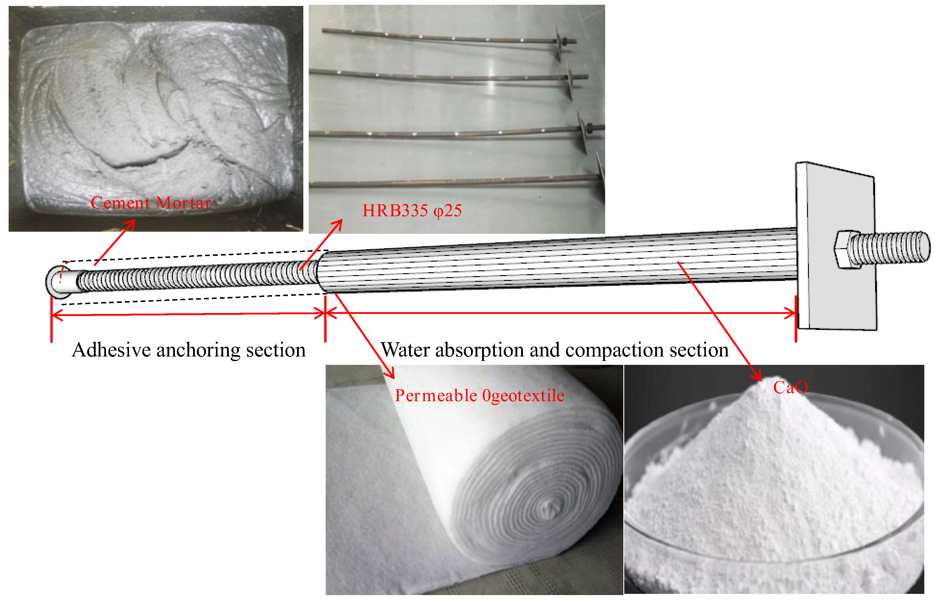
2.1. Structure and Construction of Water-Absorbing Squeezing Anchor Rods

The water-absorbing and compaction anchoring bolt is a new type of segmented series expansion bolt improved based on the hollow grouting bolt (or threaded bolt). According to the functional characteristics of each segment, it is divided into a water-absorbing and compaction segment and a bonding and anchoring segment. The water-absorbing and compaction segment is formed by wrapping the rod body with a permeable geotextile membrane bag, which is filled with water-absorbing material mainly composed of quicklime. The bonding and anchoring segment is formed by the bonding of anchoring agent and rod body. Its basic structure is shown in Figure 1.

2.2. Working Mechanism

The development of the water-absorbing and compaction anchoring bolt is inspired by the concepts of lime pile composite foundation [31,32,33,34,35] and composite bearing arch [36,37,38]. Based on the principle of the New Austrian Tunneling Method (NATM) that fully mobilizes and leverages the self-supporting capacity of the surrounding rock, it comprehensively considers the wetting and dynamic stress adjustment processes of the surrounding rock after tunnel excavation disturbance. By adopting the technical principles of “water absorption and compaction of shallow surrounding rock, suspension and anchoring of deep surrounding rock, and composite arch bearing”, it achieves the goals of water absorption, compaction, and consolidation of the shallow surrounding rock around the tunnel, the suspension and anchoring of the deep surrounding rock, and the collaborative bearing of the shallow and deep composite arches. This effectively improves the mechanical strength parameters of the loess surrounding rock, enhances the stress state of the surrounding rock, and addresses the deformation control issues of the surrounding rock. Figure 2 shows a schematic diagram of the support provided by the water-absorbing and compaction anchoring bolt for the tunnel surrounding rock.
The working mechanism of the water-absorbing and compaction anchoring bolt is mainly embodied in the mechanisms of water absorption, expansion, and compaction, consolidation and drainage, and composite bearing in the reinforced zone. After the construction of the water-absorbing and compaction membrane bag, the quicklime, which is the water-absorbing medium filled in the geotextile membrane bag, chemically reacts with the moisture in the surrounding rock and soil mass around the tunnel. The hydration reaction of quicklime causes the membrane bag to radially expand, and the radial expansion pressure produces a compaction effect on the surrounding soil. The heat released from the hydration reaction is transferred and diffused to the surrounding soil, causing the temperature of the surrounding soil to rise, which further increases the permeability coefficient of the soil and enhances the drainage and consolidation effect of the soil. After drainage, compaction, and consolidation, the soil around the membrane bag forms a reinforced zone, effectively improving the density and strength index of the soil. After the quicklime hydration reaction is completed, the tunnel circumferential expansion, compaction, consolidation, and reinforcement zone, together with the deep anchoring zone, form a composite bearing zone to jointly bear the surrounding rock load. Compared to traditional mortar bolts, the water-absorbing and compaction anchoring bolt adopts a segmented structure of “water absorption around the tunnel and deep anchoring”, effectively solving the problem of insufficient compressive resistance or effect of the anchoring system in loess tunnels. It achieves water absorption, compaction, consolidation, and reinforcement of the surrounding rock around the tunnel, as well as the suspension and anchoring reinforcement of the deep surrounding rock, maximizing the self-bearing capacity of the surrounding rock. Its structural advantages are mainly manifested in:
(1)
Novel structure: Compared to traditional bolts, the water-absorbing and compaction anchoring bolt has an ingenious design that combines anchoring support, physicochemical improvement, and other technologies. It comprehensively considers the deformation characteristics of the surrounding rock strength under the influence of water and force, maximizing the of the surrounding rock’s self-stabilization and support structure. This structure can select different water-absorbing media and anchoring agents based on different basic parameters of the surrounding rock. At the same time, it can achieve differentiated and on-demand design, overall customization, and strong structural designability according to the scope of the surrounding rock’s loose zone and the hydraulic conduction characteristics of the surrounding rock around the tunnel. The structural system is more distinctive.
(2)
Comprehensive functions: The water-absorbing and compaction anchoring bolt can not only achieve suspension and reinforcement of loose surrounding rock but also achieve physicochemical improvement, water absorption, expansion, and compaction, thermodynamic drainage and consolidation, ion exchange, gelation, and calcification of the surrounding rock around the tunnel. Combined with arches or thin steel plates, it can also achieve a fitting support for the tunnel wall and attain the collaborative bearing of shallow and deep composite arches.
(3)
Wide application range: The structure of the water-absorbing and compaction anchoring bolt is easy to customize according to demand, has strong adaptability and good integrity, and can be constructed quickly using mechanization. It can not only be applied to the active reinforcement of soft surrounding rock tunnels during construction but also to the repair and reinforcement of tunnels during operation.

3. Experimental Design

3.1. Test Objectives

The water-absorbing compaction anchoring bolt, as a new type of structural anchor, still requires experimental and engineering validation in terms of its working mechanism, theoretical calculations, as well as its water-absorbing compaction consolidation effect and uplift resistance capacity. Therefore, conducting model tests can provide a qualitative analysis and quantitative evaluation of its water-absorbing compaction consolidation range and uplift resistance capacity. This, in turn, will offer valuable insights for its theoretical calculations and analysis, structural design, and engineering applications.

3.2. Test Plan

3.2.1. Anchor Bolt Design

The design parameters of anchor bolts, such as length, spacing, anchoring material, and uplift bearing capacity, are crucial aspects of tunnel surrounding rock support design. As a new type of material and structural anchor bolt, the design parameters of water absorption and densification anchor bolts need to be determined through experimentation. To investigate the water absorption, densification, consolidation, reinforcement range, and uplift bearing capacity of a single anchor bolt, this experimental study referred to the design parameters of anchor bolt support in loess tunnel systems. The selected water absorption, expansion, and densification anchor bolt had a total length of 2.5 m, with a circumferential and longitudinal spacing of 1.2 m × 1.5 m. Both the length of the water absorption and densification segment and the bond anchorage segment were 1.0 m. To facilitate the anchor bolt pull-out test, a 0.5 m exposed segment was reserved. Anchor bolts with different diameters, including water absorption and densification anchor bolts and ordinary mortar anchor bolts, were designed as the experimental control groups. The design parameters of the anchor bolts are shown in Table 1.

3.2.2. Test Materials

The experiment was conducted in a model test box, and the main test materials used included loess soil, water-absorbing expansion and densification anchor bolts, permeable geotextile, quicklime, impermeable membrane, P.O42.5 ordinary Portland cement, and graded fine sand. The details of the test model box and test materials are as follows:
(1)
Model Box
The test model box was welded using galvanized square steel, with the dimensions of 3.0 m in length, 2.5 m in width, and 2.5 m in height. The sides of the model box were enclosed with 2.0 cm thick acrylic panels, and the bottom was paved with profiled steel plates. The front view of the model box is shown in Figure 3.
(2)
Loess Soil
The soil used in the experiment was obtained from the excavation of Q3 loess at a certain tunnel. After being transported back, it was air-dried, crushed, rolled, and sieved through a 5.0 mm screen for later use. The physical property indicators of the undisturbed soil are shown in Table 2.
To ensure that the test measured the water absorption, compaction, and consolidation effects, as well as the consolidation scope of the water-absorbing and compaction anchoring bolt under controllable conditions, measures such as layered spreading, layered compaction, and interface roughening were adopted during the soil filling process in the model box. Additionally, during the filling process, ring cutter sampling and moisture content testing were conducted to strictly control the filling density and moisture content. To prevent moisture migration between soil layers with different moisture contents, plastic films were used to isolate the moisture between high and low moisture content soil layers. The control parameters for soil filling in the test model box, as well as the measures to ensure soil density and moisture content, are shown in Figure 4.
(3)
Water Absorption and Densification Anchor Bolt
The water absorption and densification anchor bolt is an improved version based on the traditional threaded mortar anchor bolt. It is divided into two segments: the water absorption and densification segment, and the mortar bonding and anchoring segment. The water absorption and densification segment is wrapped around the rod body with a permeable geotextile membrane bag, which is filled with quicklime as the water-absorbing medium. The quicklime has an average particle size of 0.5 mm, a calcium oxide content of 85%, and an average bulk density of 11.7 kN/m3. The bonding and anchoring segment is made of self-mixed ordinary Portland cement (P.O42.5) mortar, with a mass ratio of cement to fine sand to water of 1:1:1.5, and the mortar has a strength grade of M30. The structural schematic of the water absorption and densification anchor bolt is shown in Figure 5, and the physical parameters of the permeable geotextile membrane bag are listed in Table 3.

3.2.3. Sensor Layout

The equipment used in the experiment mainly included soil pressure cells (TY) for measuring the compaction effect, pore water pressure gauges (KY), soil moisture meters (SF), and soil temperature sensors (T). Additionally, there were smart anchor pull-out testers for measuring the ultimate tensile capacity of the anchors, as well as a computer data acquisition system. The schematic diagrams of the measurement sensors and testing system for the plane position of the anchor rod inside the model box and the radial and vertical burial depth around the anchor rod are shown in Figure 6 and Figure 7, respectively.

3.2.4. Test Procedure

The main steps of the test procedure included: filling the soil into the model box → positioning the anchor installation location → forming holes for the mortar anchoring segment using a Luoyang shovel → grouting and anchoring the mortar anchoring segment → laying a waterproof plastic membrane → pre-embedding PVC pipes for hole formation → filling the soil → embedding sensors → filling the soil to the design elevation → filling the water-absorbing medium → data collection → conducting the 28-day anchor pull-out capacity test → excavation verification → organizing and analyzing the data. The images of the test process are shown in Figure 8.

3.3. Result Analysis

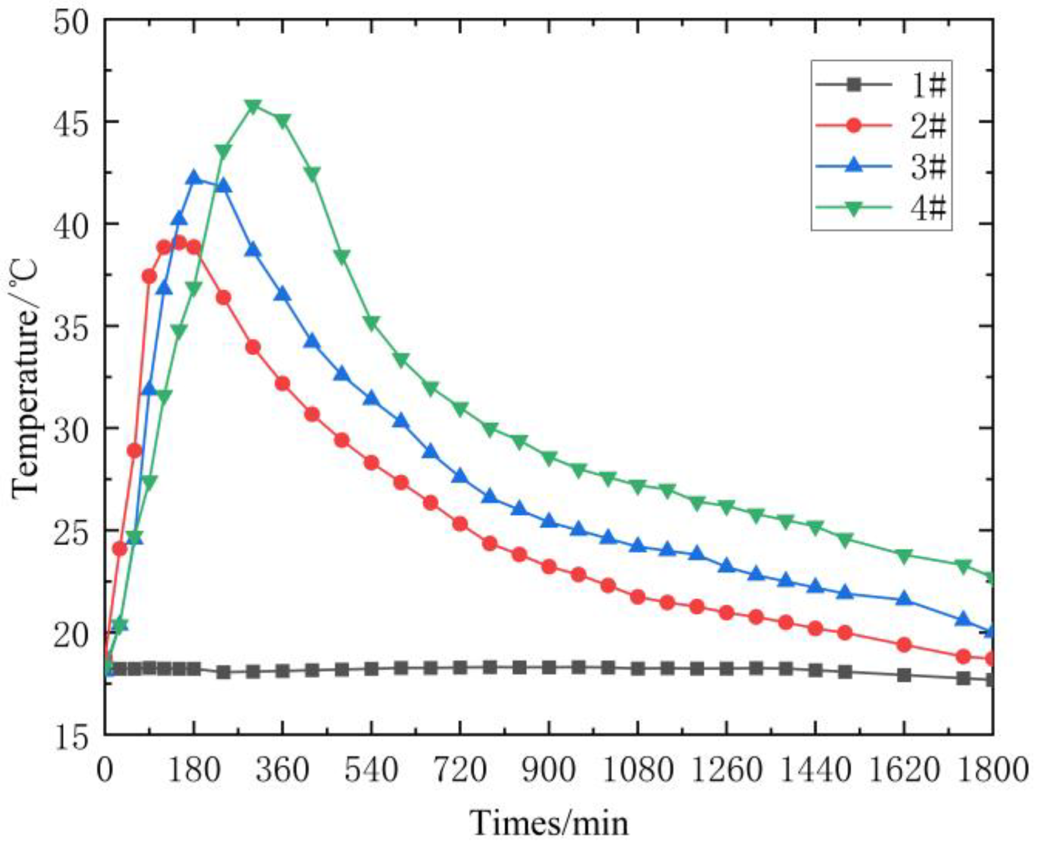
3.3.1. Temperature Change Pattern

The essence of the heat released when quicklime absorbs water is the chemical exothermic reaction that occurs when calcium oxide meets water. The chemical exothermic reaction equation and changes in various physical quantities are shown in Table 4:
According to Table 4, it is known that 3.1 kg of calcium oxide requires 1 kg of water for complete reaction, releasing approximately 1118 kJ of heat. The exothermic reaction of quicklime absorbing water and curing forms a cylindrical heat source inside the membrane bag. The temperature of this heat source is transmitted and diffused into the surrounding soil mass until the exothermic reaction ends, and the soil temperature naturally cools down. Figure 9 shows the soil temperature variation curves at a radial distance of 5 cm from the membrane bag for anchors of different diameters. According to Figure 9, the soil temperature around the 1# mortar anchor remains constant, consistent with the natural soil temperature, maintaining approximately 18 °C. Due to the exothermic reaction of quicklime absorbing water and curing in the 2#, 3#, and 4# water-absorbing and compaction anchoring anchors, the soil temperature around these anchors exhibits a pattern of rapid initial increase followed by a slow cooling and decrease, generally undergoing four stages: initial contact, rapid reaction, slow cooling, and stabilization. During the initial stage, before the quicklime starts to come into contact and react with water, the temperature of the surrounding soil remains relatively stable, close to the natural soil temperature. In the rapid reaction stage, once quicklime begins to absorb water and undergo a curing reaction, releasing a large amount of heat, the soil temperature around the membrane bag rises rapidly. The curve slope is relatively large during this stage, indicating a quick temperature rise. In the slow cooling stage, as the quicklime curing reaction proceeds, the heat release gradually decreases, and the soil temperature around the membrane bag begins to decline slowly. The curve slope is relatively small during this stage, indicating a relatively slower temperature drop. In the stabilization stage, after the quicklime curing reaction is completely finished, the soil temperature around the membrane bag gradually stabilizes, returning to the natural soil temperature level. For water-absorbing and compaction membrane bags of different diameters, due to variations in the mass of filled quicklime, the heat release during water absorption and curing, as well as the duration of heat release, will also differ, resulting in different temperature diffusion ranges. The peak soil temperatures around the 2#, 3#, and 4# water-absorbing and compaction anchoring anchors are, respectively, 39.1 °C, 42.2 °C, and 45.8 °C, with the temperature peaks occurring 3–6 h after the start of the curing reaction. After 30 h, the soil temperature cools down to the natural temperature.
Figure 10 shows the variation curves of the soil temperature distribution along the radial direction around different anchors. From Figure 10, it can be observed that the temperature distribution along the radial direction around different water-absorbing and compaction anchoring anchors exhibits the same pattern. Specifically, as the radial distance from the membrane bag increases, the soil temperature decreases. With the expansion of the water-absorbing and compaction consolidation zone, the rate of temperature decay along the radial direction exhibits a characteristic of initial slow decay followed by rapid decay.

3.3.2. Change Rule of Pore Water Pressure

Due to the permeability coefficient of the water-absorbing and compacting membrane bag being greater than that of loess, the pore water in the soil around the anchor rod experiences radial seepage. The quicklime in the water-absorbing and compacting section absorbs water, matures, and releases heat, forming a cylindrical heat source in the soil. As the temperature of the soil around the anchor rod rises, differences in the thermal volume expansion between soil particles and pore water lead to the generation and growth of pore water pressure. Figure 11 shows the curves of pore water pressure in the soil around water-absorbing and compacting membrane bags of different diameters over time. According to Figure 11, during the heat release process of quicklime absorption and maturation, under the combined effects of compaction stress and temperature, water in the soil around the anchor rod moves radially, resulting in a higher pore water pressure closer to the anchor rod. As the maturation reaction progresses, the compaction stress and soil thermal consolidation continue to develop, leading to a pattern of pore water pressure initially increasing and then decreasing, ultimately stabilizing. Meanwhile, as the degree of soil consolidation decreases with the increase in the distance from the anchor rod, the peak pore water pressure also correspondingly decreases. The larger the diameter of the water-absorbing and compacting membrane bag, the longer the time required for the complete maturation of the quicklime, and the greater the radial expansion and compaction stress and heat source temperature, resulting in a higher peak pore water pressure around the anchor rod. The peak pore water pressures at a 5 cm distance from the surrounding areas of the 2#, 3#, and 4# water-absorbing and compacting anchor rods are, respectively, 28.8 kPa, 29.6 kPa, and 30.2 kPa. The peak pore water pressure occurs 4–6 h after the start of the maturation reaction, synchronizing with the peak temperature time.

3.3.3. Variation in Compaction Stress

After water absorption and expansion, the compaction segment radially compresses the surrounding soil. Under the combined effects of temperature and radial stress, the soil undergoes drainage and consolidation, with the radial compaction stress determining the effectiveness of this process. Figure 12 shows the curves of compaction stress in the soil around water-absorbing and compacting membrane bags of different diameters over time. According to Figure 12, the 1# mortar-bonded anchor rod does not generate compaction stress in the surrounding soil due to the absence of an expansion force source. However, for the 2#, 3#, and 4# water-absorbing and compacting anchor rods, the quicklime absorption and expansion create an expansion force source in the radial direction of the membrane bag, prompting the surrounding soil to generate radial compaction stress. The compaction stress at each measurement point exhibits the characteristics of slow initial growth, subsequent rapid growth, and finally gradual stabilization. Initial Stage: In the early stage after the anchor rod is installed and begins to absorb water and expand, the radial earth pressure remains relatively stable or only exhibits minor changes since the expansion has not significantly affected the surrounding soil. Growth Stage: As the quicklime absorbs water, expands, and undergoes a curing reaction, the surrounding soil of the anchor rod begins to experience radial compaction, leading to a gradual increase in the radial earth pressure. The growth rate during this stage may vary depending on the soil properties, anchor rod diameter, and characteristics of the expansion material. Peak Stage: When the expansion of the anchor rod reaches a certain level, the compaction effect on the surrounding soil also maximizes, resulting in the radial earth pressure reaching its peak. The time at which the peak occurs depends on the reaction rate of the expansion material and the consolidation characteristics of the soil. Stable Stage: After the peak, as the soil gradually drains and consolidates and the expansion effect of the anchor rod weakens, the radial earth pressure tends to stabilize. However, this stable state may represent a dynamic equilibrium process where the earth pressure fluctuates within a certain range.
The larger the diameter of the water-absorbing and compacting membrane bag, the greater the radial expansion and compaction stress, and the longer the time required to reach stability. The closer the distance to the membrane bag, the greater the expansion and compaction stress. The peak radial compaction stresses at a 5 cm distance from the surrounding areas of the 2#, 3#, and 4# water-absorbing and compacting anchor rods are, respectively, 15.7 kPa, 42.2 kPa, and 48.2 kPa. The peak stress occurs 6–10 h after the start of the maturation reaction, lagging behind the peak temperature time.
Figure 13 shows the variation curve of compaction stress in the soil surrounding a water-absorbing and compacting membrane bag along its radial direction. As can be seen from Figure 13, the distribution trend of compaction stress in the soil surrounding water-absorbing and compacting anchoring rods of different diameters is the same along the radial direction. The larger the expansion force source is, the greater the transmission range of compaction stress will be, which is characterized by a slow decrease followed by a rapid decrease along the radial direction.

3.3.4. Analysis of Physical Property Indicators of the Soil in the Consolidation Zone

Based on the chemical equation of the hydration and curing reaction of quicklime, a theoretical analysis was conducted on the density and moisture content of the surrounding soil after a single water-absorbing and compacting anchoring rod underwent water absorption, expansion, compaction, and consolidation. The mass increment in the water consumed from the soil by the chemical reaction between quicklime and water is:
Δ m w = π D 2 4 × 0.31 ρ C a o ( 1 n C a o )
where Δ m w is the mass of water consumed by the chemical reaction; ρ c a o ,   n c a o are the density of calcium oxide particles and the porosity, respectively; and D is the initial diameter of the water-absorbing and compacting section of the anchoring rod.
Taking a unit volume of soil for the calculation, and assuming a uniform distribution of the moisture content within the range affected by expansion and compaction, the average increment in the moisture content reduction in the soil due to water absorption by quicklime is:
Δ ω = Δ m w m s = π 4 D 2 × 0.31 ρ C a o ( 1 n C a o )
After quicklime absorbs water and expands, it compacts the surrounding soil, resulting in a decrease in the void ratio of the soil and an increase in the density of the soil between piles. The range of compaction influence is taken as 3–4 times the diameter of the water-absorbing and compacting section. Taking a unit volume of soil for the calculation and assuming a uniform distribution of voids within the range affected by expansion and compaction, the average increment in the decreased void ratio in the soil is:
Δ e = Δ V v V s = π 4 [ D 2 ( η D ) 2 ]
where Δ e is the increment in the soil void ratio before and after compaction and η represents the expansion coefficient.
The water absorption, heat release, and expansion–compaction process of the water-absorbing and compaction anchoring section of the anchor bolt promote soil consolidation, reduce the soil moisture content, decrease the soil void ratio, and improve the soil shear strength parameters. The shear strength of the soil within the reinforced area is:
τ f t = c + γ s a t z tan φ + Δ σ r U ¯ s ( θ ) tan φ
where c ,   φ are the cohesion and internal friction angle of the soil, respectively, both of which are functions of dry density and moisture content; and γ s a t ,   Δ σ r represent the buoyant unit weight of the soil and the additional stress caused by expansion and compaction, respectively. U ¯ s ( θ ) represents the average degree of consolidation of the soil surrounding the anchor bolt and z represents the distance from the calculation point to the ground surface.
To verify the water absorption, expansion, compaction, and consolidation effects of the water-absorbing and compaction anchoring section, an excavation verification was carried out on this section after the test. During the excavation, a vernier caliper was used to measure the radial volumetric expansion of each anchor bolt, and a soil sampler was employed to take samples at radial intervals of 5 cm, 10 cm, and 10 cm along the anchor bolt for the analysis of the soil moisture content and density. The excavation test photos are shown in Figure 14. Table 5 presents the results of the radial expansion, moisture content, density, void ratio, and other physical parameter indicators at the 10 cm radial position obtained from the excavation test. The test results in Table 5 demonstrate that the water-absorbing and compaction anchoring section has a significant effect on expanding, compacting, and consolidating the surrounding soil. After the test, the soil moisture content decreased by 3.3–4.9%, and the density increased by 3.5–10.5%, effectively improving the soil strength parameters.

3.3.5. Analysis of Pull-Out Capacity

As an important component of the anchor–shotcrete support, anchor bolts must have a certain anchorage and pull-out capacity. For a water-absorbing and compaction anchoring bolt, as a new type of functional anchor bolt, its ultimate pull-out capacity is also an important parameter of concern in its design. Figure 15 shows the ultimate load–displacement curves of anchor bolts 1#, 2#, 3#, and 4#. As can be seen from Figure 15, the load–displacement curve of the anchor bolts is nonlinear. With the uniform increase in the load, the displacement of the anchor bolts gradually increases. The ultimate pull-out capacity of the mortar-bonded anchor bolt 1# is 9.2 kN, while the ultimate pull-out capacities of the water-absorbing and compaction anchoring bolts 2#, 3#, and 4# are 11.6 kN, 12.2 kN, and 12.8 kN, respectively. The ultimate pull-out capacity of the water-absorbing and compaction anchoring bolts is better than that of the mortar-bonded anchor bolt. Compared to anchor bolt 1#, the pull-out capacities of anchor bolts 2#, 3#, and 4# are increased by 26.1%, 32.6%, and 39.1%, respectively.
The variation patterns of temperature, pore water pressure, and compaction stress around the soil mass surrounding the water-absorbing and compaction anchoring anchor rod, as well as the physical property parameters of the soil mass in the consolidation zone, are generally consistent with those observed around lime piles in composite foundations [31,34] and micro-lime piles and soil-nailing composite supporting structures [35,39]. This truly reflects the qualitative laws of water–heat–force changes during the water absorption, curing, and exothermic reaction process of the water-absorbing and compaction anchoring anchor rod. The water-absorbing and compaction segment of the anchor rod effectively improves the density of the soil mass in the water-absorbing and compaction consolidation zone and enhances the soil strength parameters. On the other hand, the mortar-anchored anchor rod does not have a water-absorbing and compaction consolidation effect, and there is no significant change in the density and strength parameters of the soil mass above it. At the same time, due to the expansion effect of the water-absorbing and compaction segment of the anchor rod, an enlarged head is formed, which increases the close contact between the water-absorbing and compaction segment and the surrounding rock and soil mass, creating a stronger mechanical locking effect. During the pull-out process of the anchor rod, the frictional resistance between the enlarged head and the soil interface is greater than that of the mortar-anchored anchor rod. Therefore, the pull-out capacity of the water-absorbing and compaction anchoring anchor rod is higher than that of the mortar-bonded anchoring anchor rod.
After water absorption and expansion, the water-absorbing and compaction anchoring bolt exhibits the characteristics of an underreamed anchor bolt. The ultimate pull-out capacity of the underreamed section is mainly provided by the lateral resistance between the side of the underreamed section and the soil, as well as the end resistance of the underreamed section. The mechanical calculation model for the underreamed anchor bolt was established as shown in Figure 16, and its pull-out capacity calculation formula is as follows:
Q = Q 1 + Q 2 + Q 3 = 2 π r 0 L 1 τ f + 2 π ( r 0 + u r ) L 2 τ f t + π ( u r 2 + 2 u r r 0 ) P D
where Q 1 ,   Q 2 ,   Q 3 are the pull-out resistance provided by the side resistance from the bonded and anchored section, the side resistance from the expanded section due to swelling, and the increased pull-out force resulting from the normal pressure on the end face of the underreamed section, respectively; L 1 ,   L 2 represent the length of the bonded and anchored section and the length of the water-absorbing and compaction section, respectively; r 0 is the radius of the water-absorbing and compaction membrane bag; u r is the increment in the radius due to swelling and compaction; τ f is the frictional shear strength between the sidewall of the bonded section and the surrounding rock; τ f t is the frictional shear strength between the geotextile membrane bag of the expanded section and the surrounding rock mass in the consolidated zone; and P D is the normal pressure intensity acting on the expanded end.

4. Discussions

As a new type of series expansion anchor, the water-absorbing and squeezing anchor differs from other ordinary mortar anchors or expanded head anchors mainly in the hydro-thermal–mechanical coupling effect generated between the quicklime water-absorbing medium filled in the water-absorbing and squeezing segment and the surrounding soil. This effect effectively reduces the soil’s moisture content and porosity, enhances the soil’s shear strength parameters, and creates an expanded segment after the water-absorbing and squeezing segment expands, thereby increasing the frictional resistance between the geomembrane and the soil and subsequently improving its pull-out capacity. Therefore, the diameter and length of the water-absorbing and squeezing segment are crucial factors that determine the filling quality of the water-absorbing medium and significantly influence the water-absorbing and squeezing consolidation effect and pull-out capacity. Given the application of this new anchor in the support construction of water-rich loess tunnels, a too-small diameter of the water-absorbing and squeezing segment would severely compromise its reinforcement effect, while a too-large diameter could lead to excavation disturbances in the surrounding rock during anchor installation, potentially impacting the integrity and stability of the surrounding rock. Taking into account the anchoring mechanism of the new anchor, the length-to-diameter ratio of the water-absorbing and squeezing segment, the material properties of the water-absorbing medium, the construction process, and the expected experimental effects, and referencing relevant research findings on micro-piles and membrane bag piles [40,41,42], this experiment focused on testing anchors with three different diameters of the water-absorbing and squeezing segment: 7.5 cm, 9.0 cm, and 10 cm. The objective was to obtain qualitative laws of hydro-thermal–mechanical changes during the water-absorbing, curing, and exothermic reaction process after setting the water-absorbing and squeezing segment and to verify the practical effectiveness of the new anchor. Based on the results of this experiment, we plan to conduct further tests and numerical analyses on the water-absorbing and squeezing effects of different length-to-diameter ratios and different water-absorbing medium materials to better support the theoretical design and engineering application of the new anchor.

5. Conclusions

This paper presents the development of a novel water-absorbing and squeezing anchorage anchor. To verify its water-absorbing and squeezing effect as well as its pull-out capacity characteristics, tests were conducted on the anchor’s water-absorbing and squeezing effect and pull-out capacity. The temperature, pore water pressure, squeezing stress of the soil around the anchor, and the physical properties of the soil in the consolidation zone were analyzed. The main conclusions are as follows:
(1)
Adhering to the technical principles of “shallow surrounding rock water-absorbing and squeezing, deep surrounding rock suspension anchoring, and composite arch bearing”, a new type of segmented series expansion anchor was developed based on hollow grouting anchors (or threaded anchors). According to the functional characteristics of each segment, it is divided into a water-absorbing and squeezing segment and a bonding and anchoring segment. Its working mechanism is mainly embodied in water absorption, expansion, squeezing, consolidation, drainage, and composite arch bearing in the reinforcement zone. This new anchor enriches the supporting technology for water-rich loess tunnels.
(2)
The installation of the water-absorbing and squeezing anchorage anchor forms a cylindrical heat source in the water-absorbing and squeezing segment, causing the significant thermal consolidation of the surrounding soil. The temperature, pore water pressure, and squeezing stress of the soil around the anchor truly reflect the qualitative law of hydro-thermal–mechanical changes during the water-absorbing, curing, and exothermic reaction process. The water-absorbing and squeezing segment effectively improves the density of the soil in the water-absorbing, squeezing, and consolidation zone, enhancing the soil strength parameters.
(3)
Compared to traditional mortar bonding anchors, the water-absorbing and squeezing anchorage anchor exhibits higher pull-out capacity. As the diameter of the water-absorbing and squeezing segment increases, its expanded head becomes larger, and the influence range of water-absorbing, squeezing, and thermal consolidation also expands. Compared to anchor #1, the pull-out capacities of anchors #2, #3, and #4 are increased by 26.1%, 32.6%, and 39.1%, respectively.

Author Contributions

Conceptualization, X.R. and T.H.; methodology, T.H.; validation, X.R., F.Y. and P.H.; formal analysis, X.R.; writing—original draft preparation, X.R.; writing—review and editing, X.R. All authors have read and agreed to the published version of the manuscript.

Funding

Gansu Provincial Science and Technology Program Funding Project (No. 22JR5RA383).

Institutional Review Board Statement

Not applicable.

Informed Consent Statement

Not applicable.

Data Availability Statement

The raw data supporting the conclusions of this article will be made available by the authors on request.

Conflicts of Interest

The authors declare no conflict of interest.

References

  1. Hong, Q.; Lai, H.; Liu, Y. Failure analysis and treatments of collapse accidents in loess tunnels. Eng. Fail. Anal. 2023, 145, 107037. [Google Scholar] [CrossRef]
  2. Hong, Q.; Lai, H.; Liu, Y.; Ma, X.; Xie, J. Deformation control method of a large cross-section tunnel overlaid by a soft-plastic loess layer: A case study. Bull. Eng. Geol. Environ. 2021, 80, 4717–4730. [Google Scholar] [CrossRef]
  3. Li, P.; Zhao, Y. Performance of a multi-face tunnel excavated in loess ground based on field monitoring and numerical modeling. Arab. J. Geosci. 2016, 9, 640. [Google Scholar] [CrossRef]
  4. Zhang, X.; Wang, M.; Zhou, B.; Wang, X. Influence of factors on collapse risk of loess tunnel:a multi-index assessment model. J. Eng. Des. Technol. 2018, 16, 734–749. [Google Scholar] [CrossRef]
  5. Xu, Z.; Cai, N.; Li, X.; Xian, M.; Dong, T. Risk assessment of loess tunnel collapse during construction based on an attribute recognition model. Bull. Eng. Geol. Environ. 2021, 80, 6205–6220. [Google Scholar] [CrossRef]
  6. Sun, W.; Liang, Q.; Qin, S.; Yuan, Y.; Zhang, T. Evaluation of groundwater effects on tunnel engineering in loess. Bull. Eng. Geol. Environ. 2021, 80, 1947–1962. [Google Scholar] [CrossRef]
  7. Hong, Q.; Lai, H.; Liu, Y.; Chen, R.; Liu, C.; Xie, J. A case study on deformation characteristics of a large cross-section tunnel passing through a soft-plastic layer with different spatial locations. Arab. J. Geosci. 2021, 14, 272. [Google Scholar] [CrossRef]
  8. Shao, S.; Shao, S.; Li, J.; Qiu, B. An Analysis of Loess Tunnel Failure and its Mechanism, Advances in Civil Engineering. Adv. Civ. Eng. 2021, 6671666. [Google Scholar] [CrossRef]
  9. Wang, L.; Li, X.-A.; Qin, B.; Zheng, H.; Zheng, Z. Genesis and evolution mechanism of loess tunnels in the Loess Plateau, China. Catena 2024, 239, 107919. [Google Scholar] [CrossRef]
  10. Wang, D. Analysis of the causes of the collapse of a deep-buried large cross-section of loess tunnel and evaluation of treatment measures. Appl. Sci. 2021, 12, 161. [Google Scholar] [CrossRef]
  11. Wei, Z.; Zhu, Y. Seepage in water-rich loess tunnel excavating process and grouting control effect. Geofluids 2021, 5597845. [Google Scholar] [CrossRef]
  12. Chen, D.; Wang, L.; Sun, C.; Jia, C.; Zheng, L. Investigation of the support constraint effect and failure instability law of tunnels constructed using the New Austrian tunneling method. Sci. Rep. 2022, 12, 5811. [Google Scholar] [CrossRef] [PubMed]
  13. Yue, J.; Liang, Q.; Zhang, T.; Fan, C. Research on Mechanical Response and Time-space Distribution of Dupporting Structure of Deep-Buried Tunnel in Naturally Water-Rich Loess. Tunn. Undergr. Space Technol. 2024, 147, 105688. [Google Scholar] [CrossRef]
  14. Luo, Y.; Chen, J.; Shi, Z.; Li, J.; Liu, W. Mechanical characteristics of primary support of large span loess highway tunnel: A case study in Shaanxi Province, Loess Plateau, NW China primary. Tunn. Undergr. Space Technol. 2020, 104, 103532. [Google Scholar] [CrossRef]
  15. Indraratna, B.; Kaiser, P.K. Analytical model for the design of grouted rock bolts. Int. J. Numer. Anal. Methods Geomech. 1990, 14, 227–251. [Google Scholar] [CrossRef]
  16. Duddeck, H. Application of numerical analyses for tunnelling. Int. J. Numer. Anal. Methods Geomech. 1991, 15, 223–239. [Google Scholar] [CrossRef]
  17. Jian, L.; Chen, K. Analysis of Mechanical Characteristics and Anchoring Effect of Bolt in shallow-buried Loess Tunnels. IOP Conf. Ser. 2019, 267, 042096. [Google Scholar] [CrossRef]
  18. Guo, J.; Wang, M.N.; Tan, Z.S. Study on the mechanical mechanism of systematic anchor in large span and shallow-buried loess tunnel. Rock Soil Mech. 2010, 31, 870–874. [Google Scholar] [CrossRef]
  19. Xia, Q.; Zhu, X.; Zhang, G.; Yang, S.; Li, W. The Improved Theory of Synergetic Action Between Anchor Support System and Surrounding Rock-I·L·4S Mechanism Theory and Its Application in Tunnel Support Engineering. Geotech. Geol. Eng. 2021, 39, 3563–3572. [Google Scholar] [CrossRef]
  20. Zhao, D.; Wang, L.; Yu, Y.; Liu, J. Research status and development direction of tunnel system bolt. China Civ. Eng. J. 2020, 53, 119–128. [Google Scholar] [CrossRef]
  21. Cheng, J.-X.; Yang, S.-S.; Luo, Y.-B.; Wang, M.-S. Field test research on elimination of systematic rock bolts in weak rock tunnel. Rock Soil Mech. 2011, 32, 15–20. [Google Scholar] [CrossRef]
  22. Cheng, J.-X.; Wang, C.; Luo, Y.-B.; Gai, Q.-S.; Wu, K.-F. Experimental research on high-water-content soil tunnel without systematic bolts. Chin. J. Geotech. Eng. 2010, 32, 815–820. [Google Scholar]
  23. Tan, Z.; Yu, Y.; Wang, M.; Yang, J. Experimental research on bolt anchorage effect on large-section deep-buried tunnel in loess. Chin. J. Rock Mech. Eng. 2008, 27, 1618–1625. [Google Scholar]
  24. Wang, Z.; Su, X.; Lai, H.; Xie, Y.; Qin, Y.; Liu, T. Conception and Evaluation of a Novel Type of Support in Loess Tunnels. J. Perform. Constr. Facil. 2021, 35, 04020144. [Google Scholar] [CrossRef]
  25. Wang, Q.; Sun, L.; Jiang, B.; Xin, Z.; Guo, Y. Research and application of a tunnel active–passive cooperative control mechanism. Tunn. Undergr. Space Technol. 2024, 149, 105801. [Google Scholar] [CrossRef]
  26. Tian, M.; Gao, X.; Zhang, A.; Han, L.; Xiao, H. Study on the deformation failure mechanism and coupling support technology of soft rock roadways in strong wind oxidation zones. Eng. Fail. Anal. 2023, 156, 107840. [Google Scholar] [CrossRef]
  27. Zhao, J.; Tan, Z.; Wang, X.; Zhou, Z. Engineering characteristics of water-bearing weakly cemented sandstone and dewatering technology in tunnel excavation. Tunn. Undergr. Space Technol. 2022, 121, 104316. [Google Scholar] [CrossRef]
  28. Zhou, S.; Cheng, X.; Li, Q. Failure analysis of water gushing in excavation and application of rapid dewatering and recharge emergency measures. Eng. Fail. Anal. 2024, 159, 108074. [Google Scholar] [CrossRef]
  29. Pei, X.; Zhang, F.; Wu, W.; Liang, S. Physicochemical and index properties of loess stabilized with lime and fly ash piles. Appl. Clay Sci. 2015, 114, 77–84. [Google Scholar] [CrossRef]
  30. Li, B.; Min, F.; Zhang, N.; Ma, J.; Li, Z.; Yao, Z.; Zhang, L. Experimental study on water transfer mechanism of quicklime modified centrifugal dewatering clay. Constr. Build. Mater. 2023, 408, 133492. [Google Scholar] [CrossRef]
  31. Zhang, F.; Dong, J.; Yang, X.; Lian, B.; Wang, X. Study on the Hydro-Thermal-Mechanical Characteristics of the Lime-Soil Compaction Pile in the Forming Process. Adv. Mater. Sci. Eng. 2021, 7701423. [Google Scholar] [CrossRef]
  32. Min, F.; Ma, J.; Zhang, N.; Song, H.; Du, J.; Wang, D. Experimental study on lime-treated waste soil based on water transfer mechanism. KSCE J. Civ. Eng. 2021, 25, 1645–1652. [Google Scholar] [CrossRef]
  33. Alrubaye, A.J.; Hasan, M.; Fattah, M.Y. Engineering properties of clayey soil stabilized with lime. ARPN J. Eng. Appl. Sci. 2016, 11, 2434–2441. [Google Scholar] [CrossRef]
  34. Okyay, U.S.; Dias, D. Use of lime and cement treated soils as pile supported load transfer platform. Eng. Geol. 2010, 114, 34–44. [Google Scholar] [CrossRef]
  35. Qiao, Y.; Si, J.; Yuan, J.; Wang, Y.; Niu, X.; Ju, J.; Zhou, M.; He, L. Multi-Parameter Experimental Research on the Expansion Force Affecting Lime-Sand Piles under Preloading Pressure. Buildings 2024, 14, 1208. [Google Scholar] [CrossRef]
  36. Gao, X.; Luan, Y.; Hu, C.; Lu, W.; Sun, H.; Liu, B.; Zhou, L. Study on Bearing Mechanism and Coupling Mechanism of Steel Arch-concrete Composite Structure of Initial Support System of Large Section Tunnel. Geotech. Geol. Eng. 2019, 37, 4877–4887. [Google Scholar] [CrossRef]
  37. Wang, Z.; Cai, Y.; Xie, Y.; Zhang, M.; Lai, J.; Qiu, J.; Liu, T. Laboratory study on mechanical behavior of hollow π-type steel–concrete composite support in loess tunnel. Tunn. Undergr. Space Technol. 2023, 141, 105280. [Google Scholar] [CrossRef]
  38. Wen, J.; Yang, C.; Su, H.; Ning, D. Theoretical analysis and application of composite arch for bolt-shotcrete steel frame supported tunnel in weak and fractured rock mass. China Civ. Eng. J. 2015, 48, 115–122. [Google Scholar] [CrossRef]
  39. Dong, J.; Lian, B.; Liu, G.; Wu, X.; Shi, L. In-situ Test Study on Weak Slope Reinforcement with Lime Nail Composite Anchors. J. Basic Sci. Eng. 2024, 32, 527–545. [Google Scholar] [CrossRef]
  40. Shah, I.A.; Zaid, M.; Farooqi, M.A.; Ali, K. Numerical Study on Micropile Stabilized Foundation in Flyash. Indian Geotech. J. 2021, 51, 1099–1106. [Google Scholar] [CrossRef]
  41. Sharma, B.; Sarkar, S.; Hussain, Z. A Study of Parameters Influencing Efficiency of Micropile Groups. In Ground Improvement Techniques and Geosynthetics. Lecture Notes in Civil Engineering; Thyagaraj, T., Ed.; Springer: Singapore, 2019; Volume 14. [Google Scholar] [CrossRef]
  42. Misra, A.; Roberts, L.A.; Oberoi, R.; Chen, C.-H. Uncertainty Analysis of Micropile Pullout Based upon Load Test Results. J. Geotech. Geoenviron. Eng. 2007, 133. [Google Scholar] [CrossRef]
Figure 1. Schematic diagram of the structure of the water-absorbing and compaction anchoring bolt.
Applsci 14 06960 g001
Figure 2. Schematic diagram of tunnel surrounding rock supported by water-absorbing and compaction anchoring bolts.
Applsci 14 06960 g002
Figure 3. Front view of the test model Box.
Applsci 14 06960 g003
Figure 4. Soil filling control parameters and measures in the test model box.
Applsci 14 06960 g004
Figure 5. Schematic diagram of water absorption and densification anchor bolt.
Applsci 14 06960 g005
Figure 6. Schematic diagram of measuring sensors arranged radially along the anchor rod (unit: mm).
Applsci 14 06960 g006
Figure 7. Schematic diagram of sensor layout and testing system for vertical measurement along the anchor rod (unit: mm).
Applsci 14 06960 g007
Figure 8. Photographs of the test process.
Applsci 14 06960 g008
Figure 9. Soil temperature–time variation curve around the water-absorbing and compaction membrane bag.
Applsci 14 06960 g009
Figure 10. Radial distribution curve of the soil temperature around the water absorption and compaction section.
Applsci 14 06960 g010
Figure 11. Pore water pressure–time curve in the soil around the water-absorbing and compacting membrane bag. (a) Radial pore water pressure–time curve around the 1# anchor rod. (b) Radial pore water pressure–time curve around the 2# anchor rod. (c) Radial pore water pressure–time curve around the 3# anchor rod. (d) Radial pore water pressure–time curve around the 4# anchor rod.
Applsci 14 06960 g011aApplsci 14 06960 g011b
Figure 12. Time-varying curve of compaction stress in the soil around a water-absorbing and compacting membrane bag. (a) Radial earth pressure–time variation curve around the 1# anchor rod. (b) Radial earth pressure–time variation curve around the 2# anchor rod. (c) Radial earth pressure–time variation curve around the 3# anchor rod. (d) Radial earth pressure–time Variation curve around the 4# anchor rod.
Applsci 14 06960 g012aApplsci 14 06960 g012b
Figure 13. Variation curve of compaction stress in the soil surrounding a water-absorbing and compacting membrane bag along the radial direction.
Applsci 14 06960 g013
Figure 14. Measurement of the diameter and surrounding soil moisture content after expansion in the water-absorbing and compaction anchoring section.
Applsci 14 06960 g014
Figure 15. Load–displacement curve of anchor bolts in different test groups.
Applsci 14 06960 g015
Figure 16. Calculation model for the pull-out bearing capacity of water-absorbing, squeezing, and anchoring anchor rods.
Applsci 14 06960 g016
Table 1. Experimental design parameters for water absorption and densification anchor bolts.
Anchor Rod NumberBolt Length (m)The Length of the Water Absorption and Compaction Section (m)Length of Bonding and Anchoring Section (m)Diameter of Water Absorbing and Squeezing Film Bag (cm)Diameter of Bonding Anchoring Section (cm)Notes
1#2.5/2.0/7.5Mortar anchor rod
2#2.51.01.07.57.5Water absorption squeezing anchoring anchor rod
3#2.51.01.09.07.5
4#2.51.01.010.07.5
Table 2. Basic physical property indicators of the undisturbed soil.
Moisture Content
ω (%)
Density
ρ (g/cm3)
Specific Gravity
G s
Plastic Limit
W p
Liquid Limit
W L
Plasticity Index
I p
Hydraulic Conductivity
K (cm/s)
24.81.842.6317.426.38.846.39 × 10−7
Table 3. Test indicators for the technical parameters of permeable geotextile.
Experimental IndicatorsUnitTechnical StandardTest ResultNotes
Poor quality per unit area%200 (−5)200
Thicknessmm≥1.616
Breaking strengthkN/m≥1010.3
Standard strength corresponds to elongation%40–8050Longitudinal and hori
CBR breaking forcekN≥1.91.95Longitudinal and hori
Vertical permeability coefficientcm/sK × 10−1~−32.0 × 10⁻²
Tearing strengthkN≥0.280.285
Equivalent aperture O90mm0.05–0.20.1
Table 4. The chemical reaction equation for water absorption and the heat release of quicklime, as well as the changes in various physical quantities.
Chemical Reaction Equation CaO + H 2 O Ca ( OH ) 2 + Δ h
Molecular weight58187464.9 kJ/mol
Mass ration3.114.1
Proportion3.112.24
Volume ration111.83
Table 5. Comparative analysis of the soil physical properties before and after expansion in the water-absorbing and compaction anchoring section.
NumberRadius
2 r 0 (cm)
Moisture Content
ω (%)
Density
ρ (g/cm3)
Before the ExperimentAfter the ExperimentGrowth RateBefore the ExperimentAfter the ExperimentDecrease RateBefore the ExperimentAfter the ExperimentGrowth Rate
1#7.57.5/22.9723.1/1.431.42/
2#7.58.310.6%22.9822.213.3%1.431.483.5%
3#9.012.134.4%23.122.144.2%1.431.547.7%
4#10.013.535%23.222.064.9%1.431.5810.5%
Disclaimer/Publisher’s Note: The statements, opinions and data contained in all publications are solely those of the individual author(s) and contributor(s) and not of MDPI and/or the editor(s). MDPI and/or the editor(s) disclaim responsibility for any injury to people or property resulting from any ideas, methods, instructions or products referred to in the content.

