Article

Structural Design and Static Stiffness Optimization of Magnetorheological Suspension for Automotive Engine

School of Mechanical Engineering, Anhui Polytechnic University, Wuhu 241000, China
*
Author to whom correspondence should be addressed.
Appl. Sci. 2024, 14(16), 6975; https://doi.org/10.3390/app14166975
Submission received: 21 June 2024 / Revised: 18 July 2024 / Accepted: 6 August 2024 / Published: 8 August 2024
(This article belongs to the Special Issue Structural Optimization Methods and Applications, 2nd Edition)

Abstract

:
In light of the limitation that passive suspension can only provide vibration isolation within a specific range, a magnetorheological suspension in extrusion mode was developed. The reliability of structural parameters was ensured through theoretical analysis and numerical simulation, building upon traditional hydraulic suspension. A model linking static stiffness to the diameter of the upper extrusion plate, as well as the heights of the upper and lower liquid chambers, was established using Simulink as an evaluation index. The static stiffness performance of the magnetorheological suspension was then optimized using this model. Results indicate that while meeting the static stiffness requirements, the optimized Magnetorheological Suspension demonstrated a 29.22% increase in static stiffness (approximately 57.71 N/mm) compared to its previous state, validating the effectiveness of stiffness optimization for this system.

1. Introduction

The NVH problem of a vehicle has a significant impact on its comfort, with powertrain-generated vibrations being a key factor affecting NVH performance [1]. The suspension serves as an elastic system that connects the powertrain and the frame of an automobile. A suspension with excellent vibration isolation performance plays a crucial role in the overall NVH performance of a vehicle [2]. The reasonable static stiffness of the suspension can effectively reduce powertrain-generated vibrations, making it essential to deeply investigate the static stiffness of vehicle suspensions.
Liqin Sun [3] et al. developed a quasi-zero-stiffness suspension system that combines air spring and magnetic spring in parallel. They conducted mathematical modeling of the air spring and magnetic spring and tested the performance of the proposed suspension. The research revealed that the new suspension has a significant impact on reducing the acceleration of the vehicle body, provides effective vibration isolation for low-frequency vibrations, and lowers the natural frequency of the system. Xu Chunjie [4] established a suspension system model based on a CDC shock absorber. The analysis focused on the influence of suspension damping coefficient and suspension stiffness on the vibration characteristics of the suspension system from both time domain and frequency domain perspectives. It was found that suspension damping coefficient and stiffness are the key factors affecting the vibration characteristics of the suspension. Zhang Bao [5] established a finite element model for the lateral leaf spring suspension. The study focused on analyzing the characteristics of stiffness, deformation, and stress change with distance in the lateral leaf spring suspension. This research provides a theoretical basis and reference for the design of lateral leaf spring suspensions. Jiang Jinyu [6] proposed the optimal negative stiffness structure for the earth roller and suggested using hydraulic suspension to replace the traditional driver seat suspension system and the traditional rubber suspension in the cab. This provides an important reference for applying the optimal negative stiffness structure in other vehicle seat suspension systems, ultimately improving the driver’s ride quality. Li Luhang [7] proposed an automotive test framework to assess the reliability and stability of advanced driver assistance systems. The study utilized a non-dominated ordering genetic algorithm (NSGA-II) to optimize the damping, stiffness, and installation position of the suspension system. The research revealed that the designed suspension performance showed significant improvement compared to previous studies. Lin Zhihong [8] developed a magnetorheological fluid controllable multi-channel suspension with adjustable dynamic stiffness and damping. The study found that the application of magnetic fields to different flow channels could minimize the dynamic stiffness and transfer rate of damping harmonic force in the suspension. This research contributes to the understanding of how magnetic fields can be used to optimize the performance of multi-channel suspensions. Pan Gongyu [9] designed a magnetorheological fluid suspension with multiple inertial channels and conducted a simulation study on the dynamic characteristics of the suspension. The findings indicate that the multi-inertial channel Magnetorheological fluid suspension can enhance the vibration isolation performance of the engine at idle speed. Shen Yurui [10] designed a magnetorheological liquid-based engine mounting device and conducted a dynamic analysis of it. They established a dynamic decoupling calculation model of the magnetorheological mounting system and further optimized its structural parameters. Cai Qiang [11] proposed a new mixed-mode magnetorheological hydraulic suspension. The research demonstrates that adjusting the structural parameters and external excitation can effectively improve the magnetic induction intensity and damping force in the channel, thereby enhancing the vibration isolation performance of the suspension. This provides valuable insights for research in the field of powertrains.
In this paper, a magnetorheological suspension structure based on extrusion mode is designed. The research focuses on the magnetorheological suspension in extrusion mode, determines the main size parameters of the rubber master spring, derives the static stiffness expression of the suspension, and verifies the reliability of the designed suspension structure. The static stiffness model is constructed using the Simulink platform, with the optimization objective being the static stiffness of the suspension. A variable parameter set is designed within a specified constraint range to optimize the static stiffness of the suspension. This approach yields both the optimal static stiffness and an optimal parameter combination for the suspension structure, thereby confirming the correctness of the optimal design for the suspension structure and demonstrating the universality of this paper.

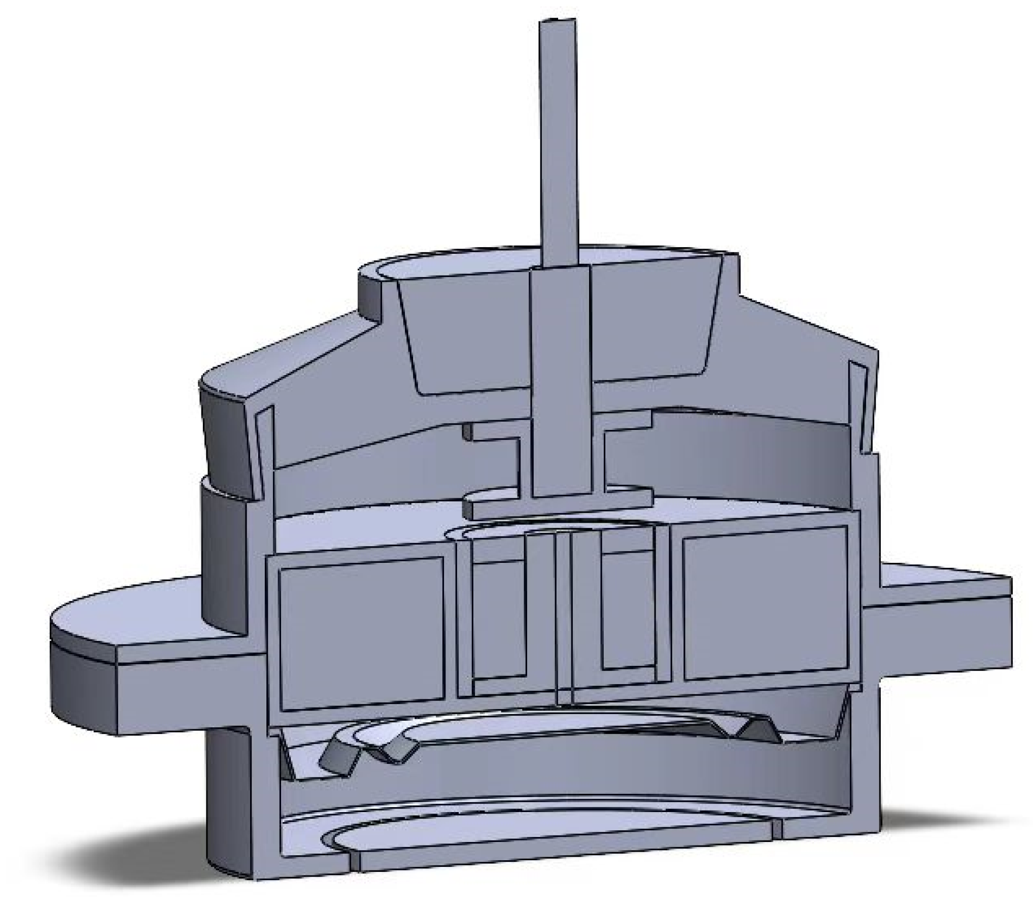
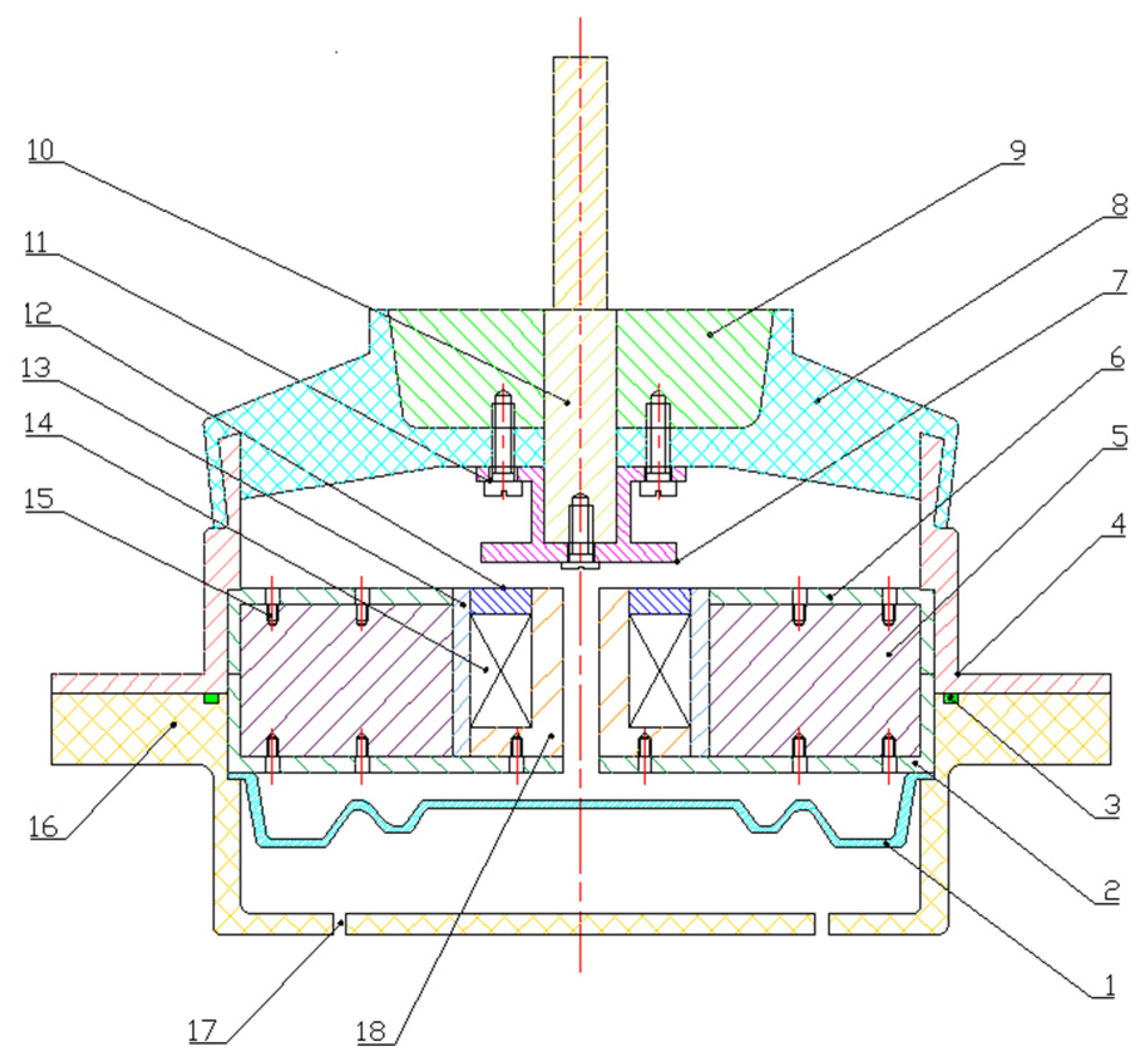
2. Magnetorheological Suspension Structure Design

In this section, we will examine the magnetorheological properties and how fluids and magnetorheological suspensions work. We have developed an extruded magnetorheological model. The traditional hydraulic suspension, the fluid, the rubber main spring, and the important magnetorheological elements of the magnetic circuit are analyzed separately as a basis for our study.

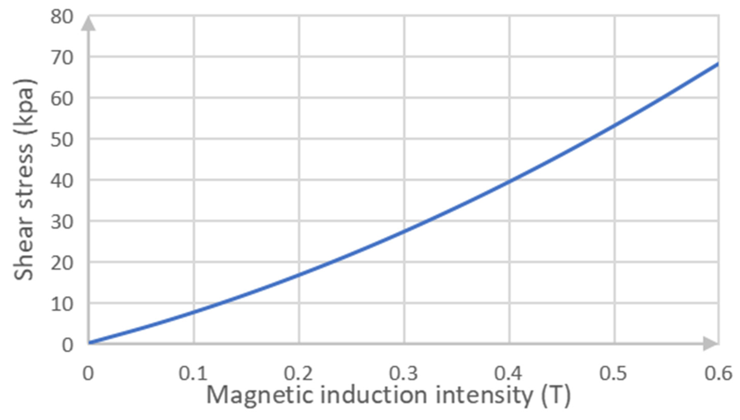
2.1. Magnetorheological Fluid Design

According to the direction of liquid flow in magnetorheological fluid and the direction of the external magnetic field, the working mode of magnetorheological fluid can be divided into extrusion, flow, shear, and mixing modes, as shown in Figure 1.
The mode selected for investigation in this paper is the shear mode of magnetorheological fluid. In the presence of a magnetic field, the field passes vertically through the upper and lower plates. When one plate is fixed in place, the magnetorheological fluid flows between the two plates, causing the other plate to move parallel due to applied force. This results in a change in flow damping force of the magnetorheological fluid between the upper and lower plates.
The relationship between the shear strain rate and shear stress of magnetorheological fluid is described as follows [12]:
τ = η γ ˙
where τ —shear stress of magnetorheological fluid;
  • η —zero field viscosity;
  • γ · —shear strain rate.
The magnetorheological fluid medium utilized in this study is a type of mineral oil. The relationship between its magnetic induction strength and shear yield stress is illustrated in Figure 2.

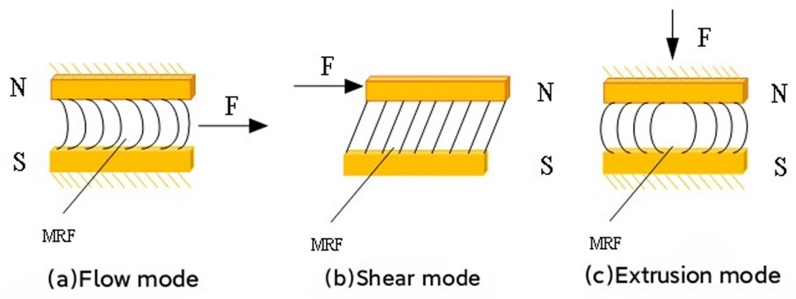
2.2. Working Principle of Magnetorheological Suspension

The main components of the magnetorheological suspension outlined in this paper consist of the upper shell, lower shell, rubber main spring, connecting rod, magnetic core assembly, damping channel, rubber bottom film, and magnetorheological fluid studio (comprising the upper liquid chamber and lower liquid chamber). The three-dimensional model of the magnetorheological mount is shown in Figure 3. The specific structure is illustrated in Figure 4.
There is a rigid connection between the suspension’s connecting rod 10 and the powertrain, causing it to vibrate in sync with the powertrain. The lower liquid chamber is formed between the upper magnetic baffle plate 6 and the rubber bottom film 1, while the upper surface of the rubber main spring 8 forms the upper liquid chamber. A flow channel is created by a gap between two extruded magnetic cores 18, and an extrusion channel is formed by a gap between the upper extruded magnetic plate 7 and its contact surface with the extruded magnetic core 18. When subjected to force, the connecting rod 10 vibrates up and down, causing magnetorheological fluid to flow through a damping channel from the upper liquid chamber to the lower liquid chamber. This movement also drives the upward and downward motion of the upper extruded plate 7. As a result of this motion, radial flow occurs as magnetorheological fluid diffuses around due to pressure from above. The excitation coil generates a magnetic field perpendicular to the upper plate. Due to radial flow, Magnetorheological Fluid flows parallel to this plate; therefore, its direction becomes perpendicular to that of said magnetic field. This makes it difficult for Magnetorheological Fluid to flow freely in response. By adjusting the current in the excitation coil or altering the size of the generated magnetic field, a controllable damping force can be achieved. This allows for varying dynamic stiffness within the suspension system while maintaining good controllability.

2.3. Suspension Magnetic Circuit Design

The purpose of magnetic circuit design is to select the appropriate magnetic circuit parameters and excitation coil. Due to the symmetry of the structure of the magnetorheological suspension magnetic circuit, only half of the magnetic circuit structure is selected as an example to facilitate the structural calculation. The structural diagram of each segment of the magnetic circuit is shown in Figure 5.
In Figure 5, r 2 r 1 is the thickness depth of the excitation coil, L 1 is the height of the excitation coil from the bottom end of the magnetic core, L 3 is the thickness of the upper extruded plate, r 3 is the radius of the upper extruded plate, f is the radius of the damping gap, and h 0 is the gap of the extrusion channel plate. The magnetic force line passes through the upper and lower magnetic cores of the magnetic circuit structure and the damping channel, in turn, to form a closed loop. According to the direction of the magnetic force line in different structures of the magnetic circuit, the suspended magnetic circuit is divided into 6 magnetoresistances, which are respectively used: R 1 is the upper plate magnetoresistive, R 2 is the outer ring area magnetoresistive of the plate gap, R 3 is the outer magnetic core magnetoresistive, R 4 is the bottom magnetic core magnetoresistive, R 5 is the extruded magnetic core magnetoresistive and R 6 is the inner ring magnetoresistive between the plates. The magnetic field line generated by the excitation coil passes successively through the area of the pair and then returns to the starting area to form a closed loop.
Based on the calculation method of the magnetic circuit, the total reluctance calculated for the designed magnetic circuit is [13].
R = R 1 + R 2 + R 3 + R 4 + R 5 + R 6
R 1 = 1 μ 0 μ 1 π L 3
R 2 = 1 μ 0 μ 2 π ( r 3 2 r 2 2 )
R 3 = L 2 h 0 μ 0 μ 3 π ( r 3 2 r 2 2 )
R 4 = 1 μ 0 μ 4 π L 1
R 5 = 1 μ 0 μ 5 π r 1 2
R 6 = 1 μ 0 μ 6 π r 1 2
where μ 0 —air permeability;
The relative magnetic permeability of regions R 2 ,   R 3 ,   R 4 ,   R 5 ,   R 6 are μ 2 ,   μ 3 ,   μ 4 ,   μ 5 ,   μ 6 respectively.
According to the magnetic circuit theory, the magnetic induction intensity of the internal and external parts passing through the plate gap without considering magnetic leakage is expressed as [14]
B 2 = N I R S 2
B 6 = N I R S 6
where S 2 —the magnetic field line outside the plate gap intersects with the operational area of the magnetorheologicalf; m 2 .
S 6 —the magnetic field line inside the plate gap intersects with the operational area of the magnetorheologicalf; m 2 .
N —number of turns of excitation coil.
A —Current.
At this juncture, it is imperative to uphold parity in the magnetic induction intensity both outside and inside the plate gap, as can be inferred from Equations (9) and (10). S 2 and S 6 ought to be equivalent. Given the orthogonal relationship between the magnetic field line and the upper extruded plate, we can derive:
π ( r 4 2 r 2 2 ) = π r 1 2
Thus, according to Formula (11), it only needs to be true: r 4 2 r 2 2 = r 1 2 .
After consulting relevant literature and considering many factors, such as the space size of the designed magnetorheological suspension, the initial structural size design of the magnetic circuit is shown in Table 1 [15].
Table 1 shows the initial structure size of the magnetic circuit.

2.4. Rubber Master Spring Design

According to the size of the rubber main spring of the existing hydraulic suspension, the main size parameters of the rubber main spring of the magnetorheological suspension are designed as follows [16]: R l = 49 mm, R h = 18 mm, H S = 15 mm, H d = 6 mm. The structure of the rubber main spring of Magnetorheological suspension is shown in Figure 6.
According to the principle of vibration isolation, the relationship between the natural frequency ( f n ) , dynamic stiffness ( k d ) and bearing mass ( M c ) of the vibration isolation system is as follows [10]:
f n = 1 2 π k d M c
The mobilization stiffness can be derived from Equation (12) as follows:
k d = ( 2 π f n ) 2 M c
Then, the static stiffness of a single suspension is
k s = ( 2 π f n ) 2 M c n d
Figure 7 and Figure 8 are the curves of the relationship between the restoring force and displacement and the static stiffness and displacement of the magnetorheological suspension rubber master spring. When Shore hardness H is equal to 50, the static stiffness of the magnetorheological suspension rubber master spring is about 195 N/mm, and the suspension rubber master spring meets the design requirements.

3. Optimization of Static Stiffness Characteristics of Magnetorheological Suspension

The vibration isolation effect of engine suspension is influenced by various component factors. In this paper, the optimization parameter selected is the static stiffness of the engine suspension. The static stiffness optimization method for magnetorheological suspension is developed using MATLAB Simulink software (MATLAB R2020a), and the optimized magnetorheological suspension’s static stiffness is determined through simulation. This demonstrates the superior internal structure of the optimized suspension.

3.1. Static Stiffness

When the load of the connecting rod of the magnetorheological suspension is F, the resetting force formed by the liquid in the upper and lower liquid chambers is in balance with the load F so that it can be obtained as follows:
F = A s ( Δ p 2 Δ p 1 )
where A s —the effective area of the extrusion plate; m m 2
  • Δ p 2 —the increased flow rate of the liquid chamber during the operation of magnetorheological suspension; m 3 / s
  • Δ p 1 —the reduced flow rate in the upper fluid chamber during the operation of magnetorheological Suspension; m 3 / s
The flow rate is calculated by the formula [17]
Δ p 2 = A s Δ x p β e V 2
Δ p 1 = A s Δ x p β e V 1
where Δ x p —displacement in the direction of x p ; m m
  • β e —modulus of elasticity; M P a
Therefore, the formula for calculating the overall stiffness of magnetorheological Suspension can be obtained, as shown in Equation (18).
F = β e A s 2 1 V 1 + 1 V 2 Δ x p
As can be seen from Equation (18), the reset force is proportional to the displacement of the upper extruded plate, so the compressed magnetorheological Liquid is equivalent to a linear hydraulic spring, and its stiffness is the hydraulic spring stiffness.
The expression of static stiffness is shown in Equation (19).
K h = β e A s 2 1 V 1 + 1 V 2
where V 1 —the volume of the upper liquid chamber; m m 3
  • V 2 —the volume of the lower liquid chamber; m m 3
Due to the actual engineering specifications, the upper extruded plate is fully submerged in the magnetorheological fluid during the operation of the magnetorheological suspension. The effective area expression of the upper extruded plate can be defined as follows:
A s = A d + A d A r + A c = 2 A d + A c A r
A d = π d 2 2
A r = π k 1 2
A c = d π k 2
where A c —the side area of the extruded plate; m m 2
  • A d —bottom area of the upper extrusion plate; m m 2
  • A r —bottom area of connecting rod; m m 2
  • d —Diameter of the upper extrusion plate; m m
  • k 1 k 2 actual engineering constant.
The volume expression of the upper fluid chamber is
V 1 = S 1 × h 1
The volume expression of the lower fluid chamber is
V 2 = S 2 × h 2
In the formula, S 1 —the upper liquid chamber fixed bottom area; m m 2
  • S 2 —the fixed bottom area of the lower liquid chamber; m m 2
  • h 1 —height of upper liquid chamber; m m
  • h 2 —lower liquid chamber height; m m
According to the above formula, the static stiffness expression of suspension can be derived as follows:
K h = β e π 2 d 2 2 + d k 2 - k 1 2 1 S 1 × h 1 + 1 S 2 × h 2
In order to better simulate and obtain more ideal optimization results, combined with the actual engineering and consult the relevant data, it is necessary to introduce the correction coefficient b . Then, the static stiffness expression is as follows [18]:
K h = b β e π 2 d 2 2 + d k 2 - k 1 2 1 S 1 × h 1 + 1 S 2 × h 2
The optimal static stiffness is related to the diameter of the upper extrusion plate, the height of the upper cavity volume, the height of the lower cavity volume, and other factors. According to the optimizable part, the optimized design variables are set as the diameter of the upper extruded plate, the height of the upper liquid chamber, and the height of the lower liquid chamber of the suspension device. According to the working conditions of the magnetorheological suspension involved in this paper and combined with engineering applications, the design parameter range of the upper liquid chamber height parameter of the magnetorheological suspension is 31–33 mm, the design parameter range of the lower liquid chamber height parameter is 33–35 mm, and the design parameter range of the upper extrusion plate diameter parameter is 40–44 mm.

3.2. Static Stiffness Optimization Results

Based on the objective function, constraint conditions, and engineering practice mentioned above, 27 groups of parameter design variables [19] are developed. These groups are designed according to the value range of the three design variables. The parameter groups are then input into MATLAB sequentially to obtain different data for each group. The specific data can be found in Table 2.

3.3. Comparative Analysis of Results before and after Optimization

In Section 3.2 of this text, 27 groups of different parameter sets were incorporated into the Simulink simulation model for resolution. The static stiffness performance of the Magnetorheological suspension before and after optimization is presented in Table 3.
By analyzing Table 3, the static stiffness of the Magnetorheological Suspension before and after optimization is compared. Following optimization, the diameter of the upper extrusion plate is reduced by 4 mm, while the height of both the upper and lower liquid chambers is decreased by 1 mm each. As a result, there is a 29.22% increase in the static stiffness of the magnetorheological suspension after optimization, equating to approximately 57.71 N/mm.

4. Magnetorheological Suspension Test Research and Result Analysis

In order to further investigate the static characteristics of magnetorheological suspension, testing is an indispensable and important method. Due to the complex structure and shape of magnetorheological suspension elements, as well as the difficulty in accurately establishing and analyzing a mathematical model, the static stiffness performance parameters of these elements are determined through static testing.

4.1. Static Performance Test Method

After allowing the Magnetorheological suspension to equilibrate in an environment with a temperature of 22~27 °C for 4~6 h, the testing is conducted under the same environmental conditions. A secondary preload is applied in the direction of the bearing of the magnetorheological suspension, with a load range from zero to 1.25 times the rated load. During this process, it is required that the speed of deformation of the magnetorheological suspension be less than or equal to 10 mm/min. The rated load is gradually increased from zero to 1.25 times for a third time and maintained for 30 s before being gradually reduced back to zero. Simultaneously, deformation values at not less than five points during loading and unloading are recorded [20]. For each load, the average value of deformation during both loading and unloading represents a static variable.
The static stiffness of suspension under rated load is [19]
K r = Δ P Δ X = 1.1 P 0 0.9 P 0 X 1.1 X 0.9
where P 0 —rated load; N
  • Δ P —static load change; N
  • Δ X —change in static deformation; m m
  • 1.1   P 0 —1.1 times the rated load value; N
  • 0.9   P 0 —0.9 times the rated load value;   N
  • X 1.1 —at 1.1 times the rated load, Magnetorheological Suspension in the direction of static deformation value; m m
  • X 0.9 —at 0.9 times rated load, Magnetorheological Suspension at the static deformation value added in the direction; m m .

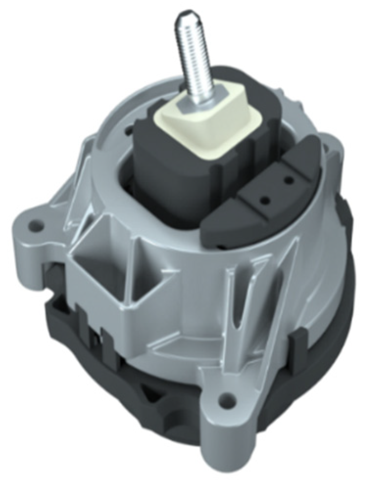
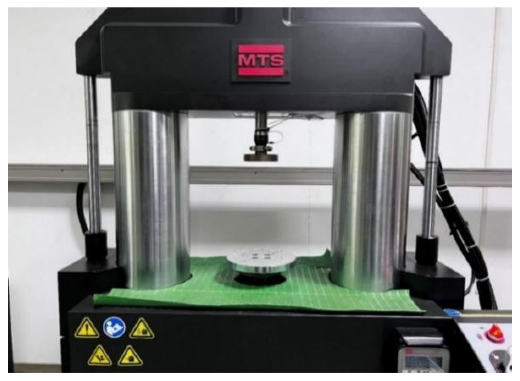
4.2. Magnetorheological Suspension Sample and Test Equipment

According to the test methods and steps outlined in the previous section, the static characteristics of Magnetorheological Suspension were tested. The test site diagram can be seen in Figure 9 and Figure 10. The Magnetorheological Suspension used in the test is the prototype produced in this paper, and its diagram is shown in Figure 11.
The testing of the dynamic properties of the magnetorheological suspension was carried out in the MTS elasticity laboratory. The static stiffness, hysteresis angle, and other parameters of rubber elastomer can be tested in this laboratory. This test adopts the MTS test platform (MTS-6000A) for testing, which is mainly composed of test platform support, an excitation output device, a sensor, a data collector, a control system, and other modules, as shown in Figure 12.
According to the test content of the test, the main technical parameters of the vibration excitation table are set as follows:
Maximum exciting force: 5000 N;
Maximum exciting amplitude: 5 mm;
The maximum speed of simple vibration: 5 m/s;
Maximum acceleration: 20 g;
Exciting frequency range: 0~200 Hz;
The range of the force sensor is −6000~6000 N;
The displacement sensor has a measuring range of −10~10 mm.

4.3. Test Results and Analysis of Magnetorheological Suspension

In the static stiffness test of the magnetorheological suspension, the rated load is calculated as P 0 = 600 N , and the different displacements corresponding to the suspension can be obtained under different applied loads, as shown in Table 4.
The measured data in Table 4 are inserted into Equation (28), according to which the static stiffness value can be calculated to be K r = 223.8   N / m m . The measured stiffness calculation results are basically consistent with the static stiffness of the rubber main spring in Chapter 2 and the optimization results of suspended magnetorheological static stiffness in Chapter 3. The results show that the theoretical calculation of static stiffness in Chapter 2 is correct, the static stiffness optimization in Chapter 5 is reliable, and the static stiffness test in this chapter is accurate.

5. Conclusions

An automobile engine magnetorheological suspension is designed based on the existing passive hydraulic suspension. The design includes the magnetorheological fluid, magnetic circuit, and rubber main spring of the suspension, ensuring their reliability. The calculation formula for the static stiffness of the permeability magnetorheological suspension is derived from the working principle of the hydraulic spring. Three design variables are selected according to this formula: the diameter of the upper extrusion plate of the suspension and the heights of both upper and lower fluid chambers. MATLAB Simulink software is utilized to optimize the static stiffness model of the suspension, resulting in an optimal parameter group for static stiffness. A related test platform is set up for processing and assembling Magnetorheological Suspension samples to explore their static characteristics and verify the accuracy and effectiveness of their optimal structure design.

Author Contributions

Z.R. had made substantial contributions to design, experimental research, data collection and result analysis; L.T. made critical changes to important academic content; Y.S. made the final review and finalization of the articles to be published. All authors have read and agreed to the published version of the manuscript.

Funding

This article belongs to the project of the “The University Synergy Innovation Program of Anhui Province (GXXT-2019-004)”, “Natural Science Research Project of Anhui Universities (KJ2021ZD0144)”, “Science and Technology Planning Project of Wuhu City (2021YF58)”. “AnHui Key Laboratory of Detection Technology and Energy Saving Devices, AnHui Polytechnic University (JCKJ2022B02)”.

Institutional Review Board Statement

Not applicable.

Informed Consent Statement

Not applicable.

Data Availability Statement

The original contributions presented in the study are included in the article, further inquiries can be directed to the corresponding author.

Conflicts of Interest

The authors declare no conflicts of interest.

References

  1. Wang, M. Basic Analysis of vehicle NVH and Engine Influence Factors. Intern. Combust. Engine Accessories 2022, 366, 103–105. [Google Scholar]
  2. Zhang, J.; Chen, R.; Yao, K. Analysis of the influence of Road Surface Roughness on Vehicle vibration. Highw. Transp. Sci. Technol. 2019, 36, 129–133. (In Chinese) [Google Scholar]
  3. Sun, L.; Su, L.; Li, Z.; Jiao, X. Research on design and characteristic of a new type of air suspension system with magnetic negative quasi-zero stiffness. Proc. Inst. Mech. Eng. Part D J. Automob. Eng. 2024, 238, 374–384. [Google Scholar] [CrossRef]
  4. Xu, C.; Xie, F.; Zhou, R.; Huang, X.; Cheng, W.; Tian, Z.; Li, Z. Vibration analysis and control of semi-active suspension system based on continuous damping control shock absorber. J. Braz. Soc. Mech. Sci. Eng. 2023, 45, 341. [Google Scholar] [CrossRef]
  5. Zhang, B.; Wang, H.; Li, Z.; Zhang, T. Stiffness design and mechanical performance analysis of transverse leaf spring suspension. J. Mech. Sci. Technol. 2023, 37, 1339–1348. [Google Scholar] [CrossRef]
  6. Jiang, J.; Nguyen, V.; Xu, S.; Xu, S. Isolating Efficiency of Soil Compactor’s Seat Suspension Using Optimal Negative Stiffness Structure under Various Deformable Terrains. SAE Int. J. Veh. Dyn. Stab. NVH 2022, 6, 209–221. [Google Scholar] [CrossRef]
  7. Lin, Z.; Wu, M. Simulation Analysis of vibration isolation performance of Magnetorheological Fluid controlled multi-channel suspension. J. Huaqiao Univ. 2022, 43, 21–28. [Google Scholar]
  8. Luhang, L.; Lin, X.; Hao, C.; Mohamed, A.A.A.; Zihao, L.; Jingyu, C. Validation and Optimization of Suspension Design for Testing Platform Vehicle. Shock Vib. 2021, 2021, 7963517. [Google Scholar]
  9. Pan, G.; Xiao, Y.; Cheng, R. Research on Optimization Vibration Characteristics of Magnetorheological Fluid Suspension for Automotive Engine. Comput. Simul. 2017, 34, 129–134+378. [Google Scholar]
  10. Shen, Y.; Fang, C.; Wang, N.; Yang, Y.; Liu, X. Design and Decoupling optimization of Magnetorheological Engine Mounting System. J. Mech. Strength 2021, 43, 693–699. [Google Scholar]
  11. Cai, Q.; Kui, H.; Deng, Z. Characteristics Analysis of squeezed Shear Hybrid Mode Magnetorheological Suspension. Automot. Eng. 2020, 11, 37–41. [Google Scholar]
  12. Pan, Y. Research on Dynamic Characteristics and Control Method of Automotive Engine Mount. Master’s Thesis, Jiangsu University, Zhenjiang, China, 2014. [Google Scholar]
  13. Cai, Q.; Kui, H.; Deng, Z. Design and optimization of Magnetorheological suspension magnetic circuit in conical channel flow mode. J. Chongqing Univ. Technol. 2021, 35, 16–22+84. [Google Scholar]
  14. Yu, L. Research on Semi-active Magnetorheological Suspension Structure Design and vibration Isolation Performance. Master’s Thesis, Jilin University, Changchun, China, 2007. [Google Scholar]
  15. Cai, Q. Research on Hybrid Mode Magnetorheological Suspension Structure Optimization Method based on Vehicle Model; Chongqing Jiaotong University: Chongqing, China, 2021. [Google Scholar]
  16. Wei, F. Research on Design and Semi-Active Control of Automotive Powertrain Magnetorheological Suspension. Master’s Thesis, Nanjing University of Aeronautics and Astronautics, Nanjing, China, 2007. [Google Scholar]
  17. Han, Z. Research on Design and Integrated Control of Automotive Magnetorheological Semi-Active Suspension System. Master’s Thesis, Jilin University, Changchun, China, 2019. [Google Scholar]
  18. Gurubasavaraju, T.M.; Kumar, H.; Arun, M. Evaluation of optimal parameters of MAGNETORHEOLOGICAL fluids for damper application using particle swarm and response surface optimisation. J. Braz. Soc. Mech. Sci. Eng. 2017, 39, 3683–3694. [Google Scholar] [CrossRef]
  19. Wu, B. Research on Powertrain mounting System and Optimization Based on Vibration Isolation Theory. Master’s Thesis, Hubei University of Technology, Wuhan, China, 2017. [Google Scholar]
  20. Wang, Y. Research on Dynamic Characteristics and Control Strategy of Engine Magnetorheological Suspension. Master’s Thesis, Chongqing University of Technology, Chongqing, China, 2022. [Google Scholar]
Figure 1. Magnetorheological fluid working mode diagram.
Applsci 14 06975 g001
Figure 2. Relationship between magnetic induction strength and shear force.
Applsci 14 06975 g002
Figure 3. Magnetorheological mount three-dimensional model diagram.
Applsci 14 06975 g003
Figure 4. Two-dimensional modeling diagram of Magnetorheological suspension; 1—rubber bottom film, 2—core base, 3—sealing ring, 4—upper shell, 5—magnetic block, 6—upper magnetic block, 7—upper extrusion plate, 8—rubber master spring, 9—Stiffener, 10—Connecting rod, 11—Sealing bolt, 12—magnetic spacer cover, 13—magnetic permeability sleeve, 14—excitation coil, 15—setting screw, 16—lower housing, 17—air vent, 18—extruded core.
Applsci 14 06975 g004
Figure 5. Structural diagram of each segment of the magnetic circuit.
Applsci 14 06975 g005
Figure 6. Structure diagram of rubber main spring.
Applsci 14 06975 g006
Figure 7. Resilience-displacement curve.
Applsci 14 06975 g007
Figure 8. Static stiffness–displacement curve.
Applsci 14 06975 g008
Figure 9. Field diagram of Magnetorheological Suspension test.
Applsci 14 06975 g009
Figure 10. Field diagram of Magnetorheological Suspension test.
Applsci 14 06975 g010
Figure 11. Prototype of Magnetorheological Suspension.
Applsci 14 06975 g011
Figure 12. MTS test equipment diagram.
Applsci 14 06975 g012
Table 1. Magnetic circuit initial structure size table.
Structural Dimensionr1r2r3L1L2L3h0f
Numerical value (mm)111820326432
Table 2. Static stiffness test results table.
Group
Number
Upper Extrusion Plate Diameter (mm)The Height of the Upper Fluid Chamber
(mm)
The Height of the Lower Fluid Chamber
(mm)
Stiffness Value Magnitude
(N/mm)
1403133204.70
2403134201.78
3403135199.04
4403233201.40
5403234197.47
6403235195.74
7403333197.30
8403334195.39
9403335192.63
10423133227.92
11423134224.67
12423135221.61
13423233224.24
14423234221.01
15423235217.93
16423333220.79
17423334217.55
18423335214.48
19443133255.18
20443134249.59
21443135245.20
22443233249.12
23443234244.53
24443235241.14
25443333244.30
26443334240.71
27443335237.32
Table 3. Compares the performance before and after optimization.
Argument d (mm) h 1 (mm) h 2 (mm) K h (N/mm)
Simulation value before optimization403234197.47
Optimized simulation value443133255.18
Table 4. Load and displacement table.
Load (N) 0.9 P 0 1.1 P 0
Displacement (mm)2.412.95
Disclaimer/Publisher’s Note: The statements, opinions and data contained in all publications are solely those of the individual author(s) and contributor(s) and not of MDPI and/or the editor(s). MDPI and/or the editor(s) disclaim responsibility for any injury to people or property resulting from any ideas, methods, instructions or products referred to in the content.

