
A Fundamental Study on Circularly Polarized Double-Loop Antennas with Quasi-Two Sources

Abstract
:1. Introduction
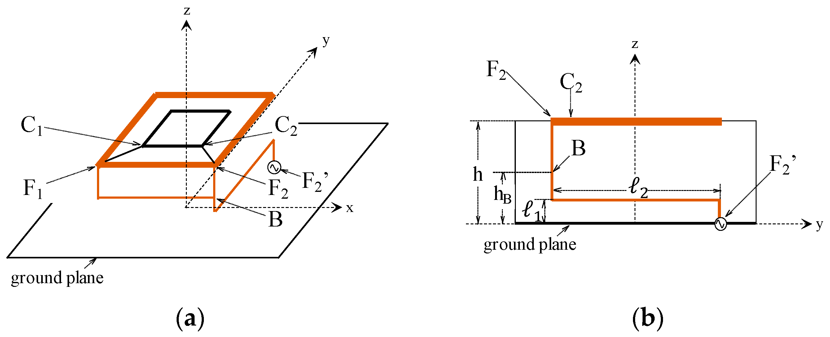
2. Design Mechanism
3. Antennas with an Outer Parasitic Loop
4. Antennas with an Inner Parasitic Loop
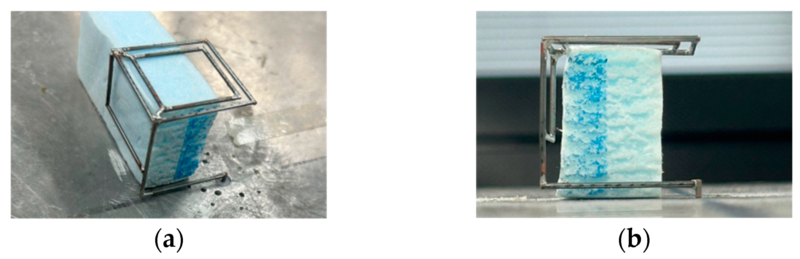
5. Experimental Work
6. Discussion
- The present antenna size is 0.25 × 0.25 × 0.25λ03, which is one-fifth as large as the reference one (0.5 × 0.65 × 0.25λ03);
- The present antenna has an unbalanced feed and can be directly excited using a coaxial line. In contrast, the reference antenna has a balanced feed and requires a complicated balun circuit design for the excitation using a coaxial line.
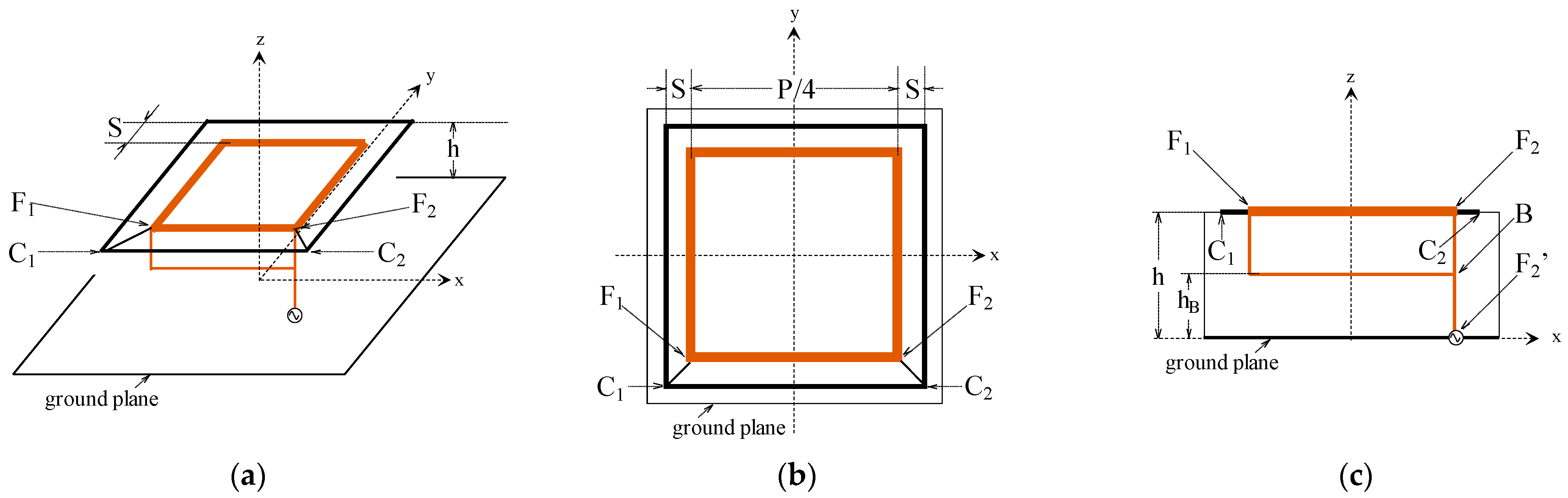
- When explaining the radiation mechanism of a wire antenna in free space, it is expected to use current distribution along the antenna arm instead of the electromagnetic field distributions (modes). The present antenna is made of wires in free space. The wire radius is ρ = λ0/200, and the loops with a spacing of S < λ0/30 are located at h = λ0/4 above the ground plane. These values of (ρ, S, h) are not chosen for a conventional patch antenna design, where the radiation mechanism is often explained using the modes;
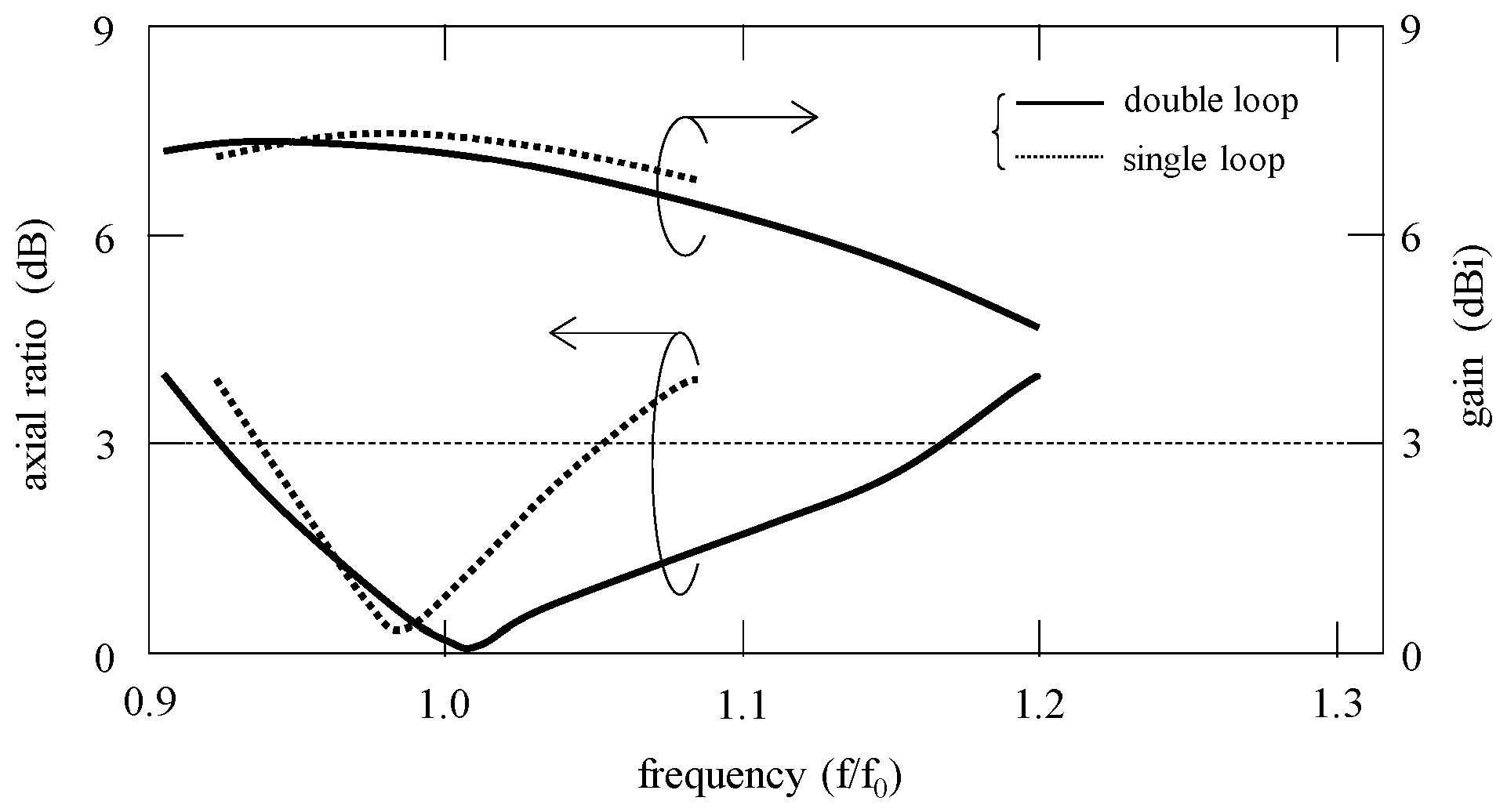
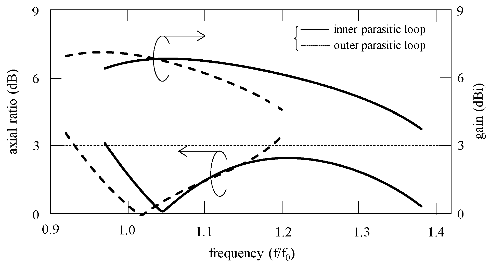
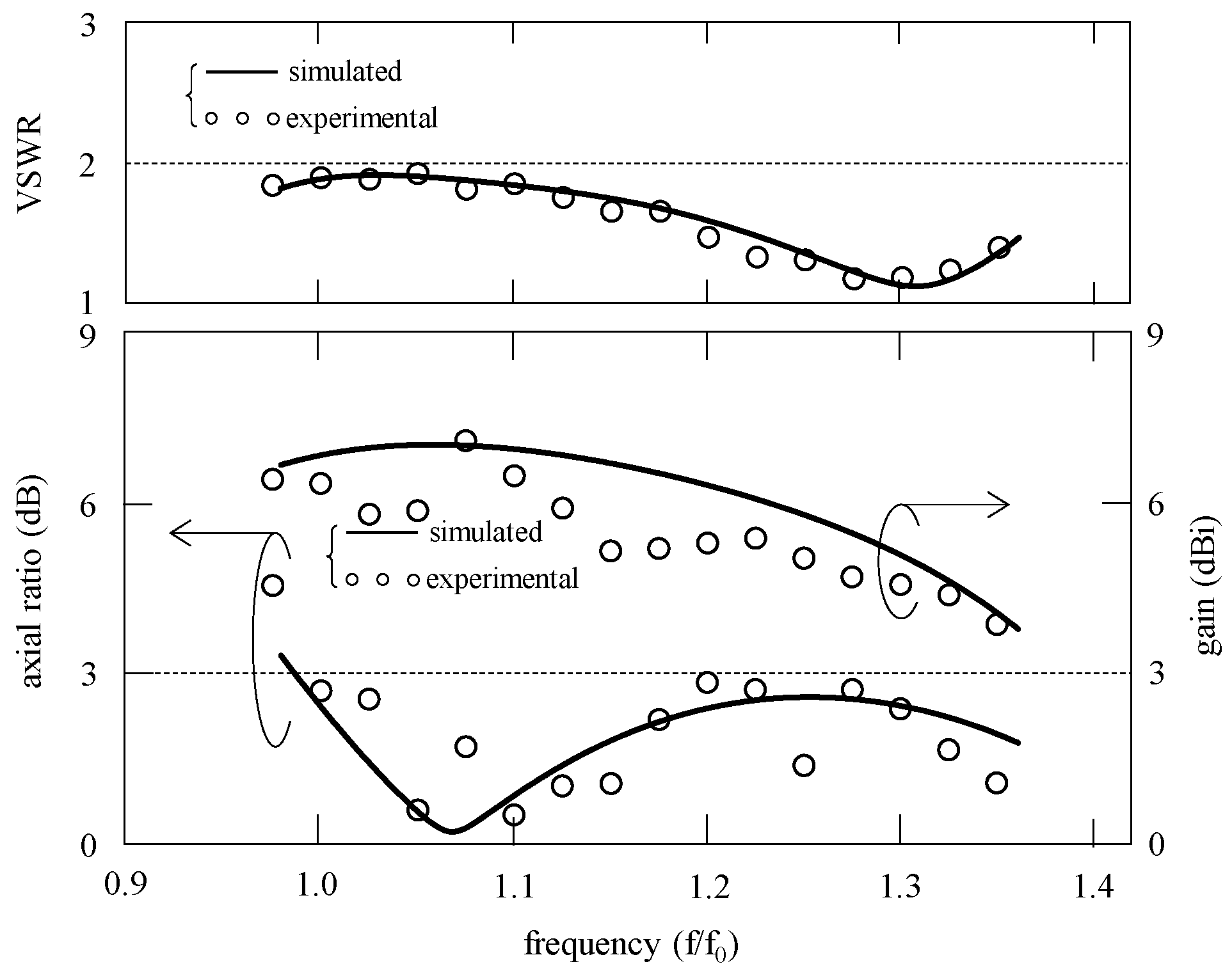
- A reason for the decrease in the gain is that the CP wave frequency range for the Inner-PL extends towards the upper frequencies, as mentioned in Figure 8. As the frequency increases from f0, the loop height electrically becomes more than a quarter of the wavelength, decreasing the gain since the physical height is a quarter of the wavelength at f0. Note that the antenna gain decreases as the antenna height above the ground plane increases from a quarter of the wavelength.
7. Conclusions
Author Contributions
Funding
Institutional Review Board Statement
Informed Consent Statement
Data Availability Statement
Conflicts of Interest
References
- Gao, S.; Luo, Q.; Zhu, F. Circularly Polarized Antennas; John Wiley & Sons, Ltd.: Chichester, UK, 2014. [Google Scholar]
- Sharma, S.; Tripathi, C.C. A comprehensive study on circularly polarized antenna. In Proceedings of the 2016 Second International Innovative Applications of Computational Intelligence on Power, Energy and Controls with their Impact on Humanity (CIPECH), Ghaziabad, India, 18–19 November 2016. [Google Scholar]
- Nadeem, I.; Alibakhshikenari, M.; Babaeian, F.; Althuwayb, A.A.; Virdee, B.S.; Azpilicueta, L.; Khan, S.; Huynen, I.; Falcone, F.; Denidni, T.A.; et al. A comprehensive survey on ‘circular polarized antennas’ for existing and emerging wireless communication technologies. J. Phys. D Appl. Phys. 2022, 55, 033002. [Google Scholar] [CrossRef]
- Ullah, U.; Ain, M.F.; Ahmad, Z.A. A review of wideband circularly polarized dielectric resonator antennas. China Commun. 2017, 14, 65–79. [Google Scholar] [CrossRef]
- Li, R.; Traille, A.; Laskar, J.; Tentzeris, M.M. Bandwidth and gain improvement of a circularly polarized dual-rhombic loop antenna. IEEE Antennas Wirel. Propag. Lett. 2006, 5, 84–87. [Google Scholar] [CrossRef]
- Li, R.; DeJean, G.; Laskar, J.; Tentzeris, M.M. Investigation of circularly polarized loop antennas with a parasitic element for bandwidth enhancement. IEEE Trans. Antennas Propag. 2005, 53, 3930–3939. [Google Scholar]
- Hirose, K.; Omori, T.; Nakano, H. Circularly polarized double- and plate-loop antennas with a single feed. IEICE Trans. Commun. 2010, 93, 997–1005. [Google Scholar]
- Murakami, Y.; Nakamura, T.; Yoshida, A.; Ieda, K. Rectangular loop antenna for circular polarization. IEICE Trans. Commun. 1995, 78, 520–527. [Google Scholar] [CrossRef]
- Hirose, K.; Tsubouchi, S.; Nakano, H. A loop antenna with quasi-two sources for circular polarisation. Electron. Lett. 2022, 58, 222–224. [Google Scholar] [CrossRef]
- Harrington, R.F. Fields Computation by Moment Methods; Macmillan: New York, NY, USA, 1968. [Google Scholar]
- Xu, L.; Bo, Y.; Lu, W.; Zhu, L.; Gu, C. Circularly polarized annular ring antenna with wide axial-ratio bandwidth for biomedical applications. IEEE Access 2019, 7, 59999–60009. [Google Scholar] [CrossRef]
- Guo, Y.; Bian, L.; Shi, X. Broadband circularly polarized annular-ring microstrip antenna. IEEE Trans. Antennas Propag. 2009, 57, 2474–2477. [Google Scholar]
- Hirose, K.; Nishino, K.; Nakano, H. Dual-loop antennas with an expanded axial ratio bandwidth. Electron. Lett. 2023, 59, e12784. [Google Scholar] [CrossRef]
- Ramirez, M.; Parron, J.; Gonzalez, J.M.; Gemio, J. Concentric annular-ring microstrip antenna with circular polarization. IEEE Antennas Wirel. Propag. Lett. 2011, 10, 517–519. [Google Scholar] [CrossRef]
- Li, W.; Zhao, Y.; Ding, X.; Gu, L.; Gao, K.; Nie, Z. Broadband circularly-polarized antenna using double loop structures with loading capacitance. In Proceedings of the 2021 International Conference on Microwave and Millimeter Wave Technology (ICMMT), Nanjing, China, 23–26 May 2021. [Google Scholar]
- Gupta, S.; Mamcu, G. Dual-band miniature coupled double loop GPS antenna loaded with lumped capacitors and inductive pins. IEEE Trans. Antennas Propag. 2013, 61, 2904–2910. [Google Scholar] [CrossRef]
- Hirose, K.; Tsubouchi, S.; Nakano, H. Series-fed loop antenna arrays with an expanded bandwidth of circular polarization. Prog. Electromagn. Res. Lett. 2023, 114, 75–81. [Google Scholar] [CrossRef]


| Study | Top View of Antenna Configuration | Location of Parasitic Loop | Method for Circular Polarization | Number of Loop Corner Connections | Spacing between Two Loops, S | 3 dB Axial Ratio Bandwidth (%) |
|---|---|---|---|---|---|---|
| [7] | 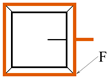 | inner | perturbation segments | 4 | Fixed (S = 0.02λ0) | 3 |
| [9] |  | — 1 | quasi-two sources | — 1 | — 1 | 12 |
| present | 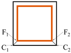 | outer | quasi-two sources | 2 | optimized (S = 0.02λ0) | 23 |
 | inner | quasi-two sources | 2 | optimized (0.02λ0 < S < 0.05λ0) | 40 |
| Study | Loop Type | Method for Circularly Polarized Radiation | 3 dB Axial Ratio Bandwidth (%) | ZinBW 1 (%) | Gain (dBi) | Operating Frequency (GHz) | Antenna Size x × y × z (λ03) z: Height |
|---|---|---|---|---|---|---|---|
| [11] | annular single | pins and slot | 19.1 | 8 3 | - 2 | 2.4 | 0.13 × 0.13 × 0.01 |
| [12] | two probes | 38 | 38 | 8 | 1.8 | 0.46 × 0.46 × 0.12 | |
| [5] | separate dual | perturbation gap | 50 | 50 | 8 | 6 | 0.62 × 0.62 × 0.3 |
| [6] | perturbation gap | 32 | 43 | 10 | 6 | 0.74 × 0.74 × 0.26 | |
| [13] | quasi-two sources | 43 | - 2 | 9.1 | 3 | 0.5 × 0.65 × 0.25 | |
| [6] | concentric double | perturbation gap | 25 | - 2 | 8 | 5.75 | 0.44 × 0.44 × 0.25 |
| [7] | perturbation segment | 3.2 | 18 | 9 | 3 | 0.25 × 0.25 × 0.1 | |
| [14] | four apertures | 23 | 23 | 7.5 | 1.4 | 0.25 × 0.25 × 0.04 | |
| present | quasi-two sources | 31 | 45 | 7.1 | 3 | 0.25 × 0.25 × 0.25 | |
| previous [9] | wire single | quasi-two sources | 12 | >12 | 7.6 | 3 | 0.25 × 0.25 × 0.25 |
Disclaimer/Publisher’s Note: The statements, opinions and data contained in all publications are solely those of the individual author(s) and contributor(s) and not of MDPI and/or the editor(s). MDPI and/or the editor(s) disclaim responsibility for any injury to people or property resulting from any ideas, methods, instructions or products referred to in the content. |
© 2024 by the authors. Licensee MDPI, Basel, Switzerland. This article is an open access article distributed under the terms and conditions of the Creative Commons Attribution (CC BY) license (https://creativecommons.org/licenses/by/4.0/).
Share and Cite
Hirose, K.; Hirose, M.; Mita, S.; Nakano, H. A Fundamental Study on Circularly Polarized Double-Loop Antennas with Quasi-Two Sources. Appl. Sci. 2024, 14, 6997. https://doi.org/10.3390/app14166997
Hirose K, Hirose M, Mita S, Nakano H. A Fundamental Study on Circularly Polarized Double-Loop Antennas with Quasi-Two Sources. Applied Sciences. 2024; 14(16):6997. https://doi.org/10.3390/app14166997
Chicago/Turabian StyleHirose, Kazuhide, Mitsuki Hirose, Shintaro Mita, and Hisamatsu Nakano. 2024. "A Fundamental Study on Circularly Polarized Double-Loop Antennas with Quasi-Two Sources" Applied Sciences 14, no. 16: 6997. https://doi.org/10.3390/app14166997