Article

Study on the Stress and Deformation of Surrounding Rock and Support Structure of Super Large Section Tunnels Based on Different Excavation Methods

1
Jiangxi Transportation Research Institute Co., Ltd., Nanchang 330200, China
2
School of Civil Engineering and Architecture, East China Jiaotong University, Nanchang 310013, China
3
Research Centre of Coastal and Urban Geotechnical Engineering, Zhejiang University, Hangzhou 310015, China
4
Jiangxi Provincial Communications Investment Group Co., Ltd., Nanchang 330052, China
5
Zhejiang Jiaogong Group Co., Ltd., Hangzhou 310051, China
*
Author to whom correspondence should be addressed.
Appl. Sci. 2024, 14(16), 7025; https://doi.org/10.3390/app14167025 (registering DOI)
Submission received: 1 July 2024 / Revised: 30 July 2024 / Accepted: 7 August 2024 / Published: 10 August 2024
(This article belongs to the Section Civil Engineering)

Abstract

:
Due to the complexity of construction sequence and the extended duration required to construct super large section tunnels, the selection of excavation method critically influences the stability of the surrounding rock and support structures. In this work, the Xiaoyuan Tunnel project in Jiangxi Province serves as the research background for employing ABAQUS software to simulate the variations in displacement and stress within the rock and support structures under three different excavation methods. The simulated results are subsequently compared and verified against monitoring data. The findings indicate that the three-benching seven-step method releases more stress (maximum principal stress value reaches 0.621 MPa) from the surrounding rock and support structures than the other methods, resulting in stress concentrations. Therefore, it is of vital significance to complete the initial support in time and seal the tunnel opening quickly. The maximum principal stress values caused by three excavation methods all appear at the arch foot position, highlighting the need for prompt reinforcement of stability support there. Compared to the CRD method and the three-benching seven-step method, the tunnel vault’s settlement value caused by the double-side drift method is reduced by 14% and 19%, respectively. Furthermore, the largest disturbance of the surrounding rock occurs under the CRD method, while the double-side drift method minimizes such disturbances, making it the preferred choice for the construction of super large section tunnels. These insights are invaluable for guiding the selection and optimization of construction methods for such tunnels.

1. Introduction

In recent years, China’s economic growth has led to a significant increase in traffic demands, prompting the construction of many highway tunnels with super large sections [1,2,3]. These tunnels exhibit a low flattening rate and significant deformation changes in the surrounding rock at the tunnel portal [4,5,6,7,8,9]. The dynamic changes in the force deformation of the surrounding rock and supporting structures occur during construction. Different excavation methods will directly affect the stability of the tunnel’s surrounding rock and supporting structure. Therefore, selecting appropriate excavation methods is crucial for ensuring the safe operation of tunnels [10,11,12,13].
Numerous scholars have conducted in-depth research on the forces and deformations affecting the rock surrounding tunnels and their supporting structures [14,15,16]. Mezger et al. [17] identified factors closely linked to the convergence of tunnel deformation, based on monitoring data. Jung et al. [18] introduced the concept of stress distribution using the center-diaphragm method and determined the optimal distance between the excavation face and the excavation sequence. Manh [19] developed a closed-form solution for the stresses and displacements around a tunnel using complex variable theory and the conformal mapping method. It is well established that stress redistribution occurs in tunnel sections at the initial stage of excavation, and stress concentration happens at the end of excavation. Thus, the stability of the rock surrounding the tunnel and the supporting structures can be effectively assessed by monitoring the change in surrounding rock stress at the tunnel opening [20,21,22,23,24]. He [25] achieved the digitization and automated analysis of structural surface information of tunnel rock bodies using image processing and structural feature extraction techniques. Zhu et al. [26] comparatively analyzed the model tests and numerical simulations, discovering that the surrounding rock damage zone gradually expands with increased burial depth. Zhu [27] extensively discussed the stability of large-depth cavern complexes using loading tests on tunnel rock hexahedra under three-dimensional stress states. Meguid [28] introduced various physical models suitable for tunnels in regions with soft soil geological conditions. Pan [29] explored the deformation and damage mechanism of peripheral rock in a super large section of a tunnel with a small clear distance, noting that high-strength support can effectively control peripheral rock deformation. Using finite element simulations, Jiang et al. [30] observed that the displacement release coefficient during tunnel excavation is influenced by the excavation method and other factors. Duan et al. [31] employed nonlinear analysis to identify the optimal excavation methods for large-span tunnels with varying levels of surrounding rocks. Wan et al. [32] demonstrated that the mechanical behavior during tunnel excavation could be managed through active control technology, supported by on-site monitoring. Active faulting in areas with strong earthquakes has always been a key problem threatening the safety of tunnel construction and operation [33,34]. Lu et al. believe that the seismic toughness of underground structures should include two parts: resistance toughness and recovery toughness [35]. Based on the probabilistic analysis method [36], the two-stage design method has been widely used in the seismic design of underground structures such as tunnels [37,38]. Therefore, it is highly necessary to consider the earthquake resistance level for tunnel structural design.
Although extensive research has been conducted on the stability of surrounding rocks and supporting structures in tunnels under various excavation methods, studies specifically addressing single-bore four-lane large-cross-section tunnels are relatively limited. Furthermore, the deformation mechanisms of super large section tunnels under different excavation methods remain insufficiently understood, particularly regarding the selection and optimization of construction schemes for these tunnels. In response to this gap, this paper presents a pioneering study using the Xiaoyuan Tunnel Project in Jiangxi Province, which is the first to feature a single-bore four-lane large-cross-section tunnel. This study establishes a three-dimensional finite element model for the tunnel using ABAQUS 6.14.4 finite element analysis software, applying three different excavation methods: the CRD method, the three-benching seven-step method, and the double-side drift method. By assessing the internal forces and deformation indices of the surrounding rock and supporting structure, this research summarizes the qualitative laws of tunnel force and deformation under various excavation conditions. The findings aim to provide valuable insights for the design and construction of excavations and supports for similar super-large-cross-section tunnels.

2. Project Overview

Situated in the Nanxiang District of Ganzhou city in Jiangxi Province, the mileage range of the Xiaoyuan tunnel is from ZK2985+180 to ZK2985+570, which is designed as a single four-lane highway tunnel. To facilitate traffic flow, its entrance and exit are uniquely designed with bamboo-cut doors. The engineering geological conditions in the area where the tunnel is located are complex, mainly consisting of rocks such as granite, with the rock mass being relatively fractured. Fracture zones are common in the tunnel site area; in particular, areas with dense fractures are more pronounced, and the rock mass condition is relatively fragmented. The corresponding longitudinal section of the tunnel is shown in Figure 1.
According to the engineering geological survey, the surrounding rock grades of the Xiaoyuan Tunnel mainly include grades III and IV, with localized areas of grade V. The main rock body of the tunnel is fine-grained biotite granite from the first phase of the Caledonian period, with fractures ranging from moderate to relatively developed. The overall state of the rock body varies from relatively intact to moderately fractured, and its formational characteristics are generally moderate, making the surrounding rock of the tunnel walls relatively stable. By checking engineering geological reports and exploration data, it is found that the RQD values of the rocks referred to in this paper range from 70 to 85, and the RMR values range from 19 to 55. The maximum burial depth of the tunnel reaches 76 m, and the deep surrounding rocks are mainly soft to hard rocks like fine-grained biotite granite, with fractured rock bodies and dense fractures. Considering the geological conditions of the G45 Daguan Highway, the burial depth of the Xiaoyuan Tunnel does not lie in a high-stress area, so the influence of crustal stress on the tunnel’s surrounding rock need not be considered.

3. Numerical Modeling of the Deformation Control of Tunnel Surrounding Rock

3.1. Model Building

In response to the specific conditions at the Xiaoyuan Tunnel site, a detailed 3D model was developed, reflecting the actual conditions of the surrounding rock and the distribution of ground stress. Using ABAQUS finite element simulation software, the construction of the surrounding rock section from ZK2985+195 to ZK2985+555 was numerically simulated and analyzed. To minimize the influence of the tunnel model boundary on computational data, distances greater than three times the tunnel excavation span were chosen as the left and right boundaries of the model, in accordance with Saint-Venant’s principle. The scope of the tunnel model area was determined based on the principle that the zone of influence from tunnel excavation ranges from 3 to 5 times the diameter of the excavation [39]. The model is established based on the following assumptions. (1) Regardless of the stratification of the surrounding rock mass, it is regarded as a continuous, single, and isotropic ideal elastoplastic medium. (2) Tunnel excavation proceeds in a step-by-step manner, and the construction of support structures is promptly carried out after each excavation stage. (3) The influence of groundwater on the excavation process is ignored. To accurately represent geostress, the vertical direction of the model was set to the z-axis and the horizontal direction to the x-axis. The 3D mesh distribution of the model is shown in Figure 2. The model uses eight-node linear hexahedral elements for simulation, with reduced integration, and adopts the Mohr–Coulomb criterion. Accordingly, the horizontal dimensions of the surrounding rock were set to 120 m, the vertical to 120 m, and the y-axis (the tunnel direction) to 20 m. The shallow buried side was set to 70 m, with 50 m for the left and right offsets. To simulate the stress state before tunnel excavation in the actual geological environment, this paper achieves a stable state of the model by applying gravity loads prior to the tunnel excavation simulation. The geostress equilibrium contour map has been added to the revised manuscript as Figure 3. The stress boundary conditions at the excavation boundary of the tunnel model are set as free boundaries, with constraints in the x-direction applied to the left and right directions, and constraints in the y-direction applied to the front and back directions. The top surface of the model is set as an unconstrained free surface, while the bottom surface of the model and the ends of the anchor rods are set with fixed constraints. The simulation of the contact interface between the lining and the surrounding rock is achieved by setting up a Contact Pair.
As the first four-lane super large section highway tunnel in Jiangxi Province, the Xiaoyuan Tunnel has a net height of 5 m, a net width of 18.25 m, a maximum buried depth of 76 m, a maximum excavated section area of 275.7 square meters, and a maximum excavated width of 22.38 m. The detailed structural parameters are shown in Figure 4. The model includes a variety of excavation methods, such as the CRD method, three-benching seven-step method, and the double-side drift method. The structural grid cells chosen resulted in a model grid divided into 31,914 nodes and 27,568 cells. The model components, such as surrounding rock and lining, were represented as C3D8R solid cells, while the anchors were modeled as B31 beam cells. Parameters for the surrounding rock and support structures required for the simulation were derived from site design and investigative data.

3.2. Properties of Model Materials

In the numerical analysis model for the Xiaoyuan Tunnel, the values of surrounding rock and soil parameters were mostly determined based on engineering conditions and geological environment. Some parameters were measured through field tests and laboratory tests. Due to the existence of the fault fracture zone (i.e., the most dangerous position along the tunnel), the ZK2985+360 tunnel section chosen as the typical simulation object of this study is located in a Grade III surrounding rock zone according to the actual engineering report; hence, the material parameters in Table 1 are mainly selected based on the soil parameters corresponding to the Grade III surrounding rock. These calculations use ideal elastic–plastic materials, with the Mohr–Coulomb criterion selected as the yield criterion to describe the mechanical behavior. Given the complexity involved in modeling the reinforcing cages in the tunnel’s primary and secondary linings, a simplification is necessary in the computational model. Specifically, the concrete and reinforcement in the primary lining are modeled as a single entity using solid units. C35 concrete is employed, and 14 I-beams are used for the anchor reinforcement. The essential calculation parameters utilized in the model are detailed in Table 1.

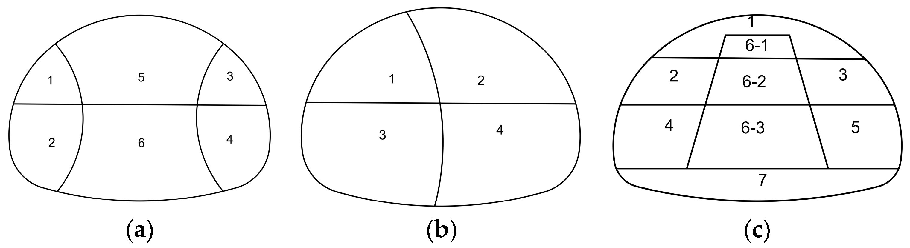
3.3. Excavation Simulation

Considering the geological conditions, engineering requirements, economic cost, construction technology, and other factors of the Xiaoyuan Tunnel, the three-benching seven-step method and the double-side drift method are widely used in the construction of large-cross-section tunnels [40,41,42]. Therefore, these three methods are simulated and analyzed, as shown in Figure 5. Figure 5a depicts the double-side drift method, which begins with the excavation and initial support of the left upper guide pit, followed by similar actions for the left lower guide pit. This process is symmetrically implemented on the right side with the sequential excavation and support of the right upper guide pit and then the right lower guide pit. Subsequently, the middle upper guide pit and middle lower guide pit are completed. The final stages involve excavating and providing initial support for the superelevation arch, followed by its casting and filling. Figure 5b details the CRD method, which starts with the excavation and initial support of the left upper guide pit to ensure the stability and safety of the construction. This is followed by the right lower guide pit’s excavation and initial support, setting the stage for the seamless progression of subsequent steps. The process continues with the left lower guide pit and the right lower guide pit, executed sequentially to maintain the coherence and stability of the excavation sequence. The final phase includes the excavation of the upward arch, along with simultaneous initial support, and the pouring and filling of the arch to complete the sequence. Figure 5c showcases the three-benching seven-step method, initiating with the excavation and initial support of the ring-shaped upper guide pit to solidify the construction sequence’s stability and safety. Following this, the left middle guide pit and the right middle guide pit are tackled sequentially. The method concludes with the excavation and initial support of the upward arch, followed by the pouring of the full-section secondary lining to enhance the structural stability of the tunnel.

4. Analysis of the Numerical Calculation Results

4.1. Surrounding Rock Stress Analysis

The surrounding rock of a tunnel prior to excavation exists in a state of crustal stress equilibrium, known as the primitive stress state [43]. The excavation sequence acts as an unloading process for the surrounding rock, altering its stress state. This alteration in stress conditions prompts stress redistribution within the surrounding rock, culminating in the formation of a new stress equilibrium state through the release of stresses. This stress release and redistribution process is essential to accommodate the geological changes induced by the excavation. The excavation-induced deformation and displacement of the surrounding rock alter the original distribution of ground stresses, ultimately leading to a new equilibrium state. This critical process of stress release and rebalancing is fundamental to ensuring the stability and safety of tunneling projects and, as such, necessitates thorough analysis and evaluation.
Figure 6 shows the major principal stress cloud diagrams for the three construction methods. Based on the distribution of major principal stresses depicted in Figure 6, significant changes in tunnel stresses can be observed at specific locations, such as the arch crown, arch base, arch waist, and arch feet. After organizing and analyzing the simulation results, it was found that the maximum principal stress occurs at the position of the right arch foot for both the double-side drift method and the CRD construction method. Specifically, the double-side drift method resulted in a maximum principal stress of 0.451 MPa at the right arch footing, whereas the CRD method recorded a maximum principal stress of 0.216 MPa at the same location. The three-benching seven-step method, on the other hand, displayed a different stress distribution, with the maximum principal stress reaching 0.621 MPa at a distinct point in the upper part of the right arch. These findings illustrate the variability in stress distribution in the surrounding rock during tunnel excavation by different methods. These results highlight the differences in the distribution of surrounding rock stress during tunnel excavation across different construction methods. The double-side drift method and the CRD method exhibit relatively lower maximum principal stresses at the right arch foot, whereas the three-benching seven-step method shows higher maximum principal stresses at a specific point on the upper right arch.
Based on the analysis above, the double-side drift method demonstrates certain advantages for large section tunnel excavations. Compared to the three-benching seven-step method and the CRD method, the double-side drift method exerts less impact on the surrounding rock stress. Throughout the tunnel excavation sequence, significant variations are observed in the stress changes and trends within the surrounding rock due to these three methods. However, the double-side drift method impacts the surrounding rock stresses to a lesser extent than the other two methods. While localized stress disturbances may occur during the excavation process, these disturbances have a minimal effect on the overall stress changes in the surrounding rock.

4.2. Surrounding Rock Displacement Analysis

During the excavation and support process of large section tunnels, the top of the arch typically experiences the maximum vertical displacement, while the bottom of the arch tends to undergo the maximum uplift displacement. As shown in Figure 7, the deformation of the surrounding rock continues to increase with each excavation and support step until stabilization is reached. However, the extent of disturbance and deformation of the surrounding rock varies significantly depending on the construction method used. The three-benching seven-step method leads to greater disturbance of the surrounding rock and more pronounced deformation because it involves excavating all of the perimeter rock of the upper step in the first excavation step, resulting in a significant release of perimeter rock pressure. Consequently, the maximum vertical displacement caused by this method is primarily due to the settlement of the vault. Specifically, compared to the CRD method, the three-benching seven-step method increases the settlement of the arch by 23%, the vertical displacement of the arch shoulder by 18.3%, the vertical displacement of the arch footing by 9%, and the augmentation of the arch base by 9.5%. Therefore, compared to the three-benching seven-step method, the CRD method can better control the perimeter rock displacement.
In the displacement monitoring of the actual construction process, it is noted that all displacement values recorded when using the CRD method are smaller than those obtained with the three-benching seven-step method. This observation confirms that the CRD method provides better control over perimeter rock displacement compared to the three-benching seven-step method. However, the actual measured displacement values are generally greater than the calculated values. This discrepancy occurs because the support in the numerical simulations is assumed to be instantaneously effective, whereas in the actual construction process, the support takes effect with some delay. Additionally, the support structures require a certain amount of time to solidify and reach sufficient strength, meaning that the observed displacement values are larger than those predicted by the simulations [43].
Figure 8 illustrates the displacement of the surrounding rock at the arch crown and arch base under three different excavation methods. It shows that under the double-side drift method, the changes in both arch crown settlement and arch base uplift are minimal. Compared to this method, the displacement convergence at the tunnel arch crown is reduced by no more than 14% when using the three-benching seven-step method, and the displacement convergence at the left arch shoulder is reduced by no more than 19% compared to the CRD method. Overall, after implementing the double-side drift method, the trend of changes in the left-side soil support is the most moderate, whereas with the three-benching seven-step method, the rate of change in the surrounding rock displacement is the greatest during the initial excavation of the upper soil. Several conclusions can be drawn from Figure 8. First, the double-side drift method demonstrates superior performance in controlling the displacement of surrounding rock, particularly in reducing the settlement at the arch crown and uplift at the arch base. Second, after the application of the double-side drift method, changes in the soil following support are more gradual, which may help to reduce instability during construction. Lastly, for the three-benching seven-step method, special attention needs to be given to the rate of displacement change in the surrounding rock during the initial excavation of the upper soil, along with implementing appropriate measures to minimize potential risks during the construction process.

4.3. Stress Analysis of the Support

Figure 9 illustrates the maximum principal stress distribution in the initial lining under three different excavation methods. The figure highlights that peak stress variations within the tunnel are primarily located at the arch waist and arch foot positions. According to the model’s calculations, both the double-side drift method and the three-benching seven-step method register the highest principal stress at the left arch footing, with values of 2.9 MPa and 3.1 MPa, respectively. Conversely, the CRD method shows the highest principal stress at the right arch footing, measuring 3.6 MPa. From these observations, several insights can be drawn (Figure 9). Firstly, the areas experiencing peak stresses, specifically the tunnel girdle and foot of the arch, should be carefully monitored, as these are likely sites of significant stress concentration within the tunnel structure. Secondly, the variability in stress distribution across the different excavation methods suggests that each method impacts the structural stresses differently. This variability must be thoroughly considered in the engineering design and the planning of construction sequences. For instance, when choosing an excavation method, its effects on the tunnel stresses should be evaluated individually, and appropriate strategies should be implemented to mitigate the effects of stress concentrations, thereby enhancing the overall safety and stability of the structure.
Figure 10 depicts the minimum principal stress distribution in the primary lining under three excavation methods. It reveals that all three methods exhibit the lowest principal stresses at the right arch waist position. Specifically, the minimum principal stress recorded for the double-side drift method is −9.8 MPa, for the three-benching seven-step method, it is −11.3 MPa, and for the CRD method, it reaches −13 MPa. From this analysis, several important observations can be made. First, the minimum principal stress at the right arch girdle warrants particular attention due to its potential complexity in terms of structural stresses. Second, the variation in stress distribution across different excavation methods underscores the need for a tailored approach in both design and construction phases. By understanding these differences, engineers and construction managers can implement targeted measures to enhance the stability and safety of the tunnel structure.
During the excavation process of the three excavation schemes, the minimum stress in the initial lining reaches its peak value as excavation progresses, with the rate of change gradually slowing down. For the three-benching seven-step method, the development phase of the minimum principal stress in the initial lining is concentrated during the first step of excavation, reaching its maximum after the excavation of the second set of steps, then decreasing and finally stabilizing at around −11.3 MPa. In the CRD method, the minimum principal stress changes by about 60% during the first stage of excavation. As excavation and support proceed, the rate of decrease gradually slows, finally stabilizing at −13 MPa. The double-side drift method shows a more even and gentle rate of change in the minimum principal stress of the initial lining compared to the CRD method and the three-benching seven-step method, without experiencing a concentrated release process, ultimately stabilizing at −9.8 MPa. From the above analysis, it can be seen that in large section tunnels, the double-side drift method has a smaller impact on the initial support stress compared to the three-benching seven-step method and the CRD method. This suggests that the double-side drift method may be more advantageous for managing stress during the initial phases of excavation and support.

5. Comparative Analysis of Monitoring Results and Numerical Results

5.1. Monitoring Program

The project employs a range of monitoring instruments, detailed in Table 2, to conduct a comprehensive analysis of critical displacement and mechanical parameters. These parameters include the internal displacement of the surrounding rock, the axial force of the anchor rods, the pressure of the surrounding rock, the pressure between the two layers of support, the internal force of the steel support, and the internal stress of the support (lining), among others. The specific arrangement of the monitoring points is depicted in Figure 11, while the equipment used for monitoring these parameters is listed and described in Table 2.

5.2. Monitoring and Analysis

Firstly, it is necessary to clarify that relevant monitoring equipment was installed to observe the variation in the tunnel’s stress and deformation along the entire tunnel, instead of limiting it to the ZK2985+360 section. Secondly, the geological survey report and field investigation show that there is a fault fracture zone (i.e., the most dangerous position along the tunnel) in the ZK2985+360 section. The monitoring results are displayed in Figure 12. This figure reveals that the maximum stress in the surrounding rock occurs at the location of the left arch foot. Notably, the actual monitored displacements are significantly larger than those predicted by numerical simulations. This discrepancy is primarily due to the fact that support structures in the numerical model are assumed to be applied instantaneously, whereas in the actual construction process, the application of support occurs with a relative delay. Additionally, the support materials require a certain period to undergo condensation and develop sufficient strength. Consequently, the measured displacements exceed those projected by the simulation [44]. To address this discrepancy, further exploration into the differences between the measured displacements and those predicted by simulations is necessary. Enhancing the model by incorporating actual construction conditions could improve its accuracy. To address the observed discrepancies between actual measured displacements and numerical simulations, further exploration and adjustment of the model in accordance with actual construction conditions are necessary. One potential modification could involve introducing a time delay factor for support construction within the numerical simulation. Additionally, more accurate modeling of the support’s consolidation process could enhance the precision of the simulations. Implementing these changes would improve the accuracy of numerical models, allowing them to more effectively reflect the real-world engineering conditions. This approach not only aids in predicting potential issues but also assists in developing strategies to mitigate them during the construction phase.
According to observations in Figure 12, during the excavation sequence, the minimum principal stress value was noted in the surrounding rock and initial support at the right arch waist location, aligning with the results from the numerical simulations.
The tunnel section from ZK2985+195 to ZK2985+555 was selected as a comparison section, and the double-side drift method was used for excavation and support, in line with the actual construction conditions on site. The numerical model was adjusted by setting appropriate analysis steps to simulate the actual excavation conditions. To verify the accuracy of the model, we have compared the numerical results with the monitoring results, as illustrated in Figure 13a. The construction of the support structure during numerical simulation is instantaneous, while the construction of the support structure in practical engineering is relatively delayed. Therefore, the measured displacement is greater than the simulated displacement. To further prove the validity of the model, we make another comparison with two previous case studies [45,46] on the surface settlement, shown as Figure 13b. Although there is a little difference, the trend of the curves in Figure 13 is basically the same, which also proves the efficiency of the numerical model.

6. Conclusions

This paper uses the first four-lane super large section highway tunnel in Jiangxi Province as a case study and employs ABAQUS finite element software to simulate and compare the effects of three excavation methods on tunnel excavation. The patterns of surrounding rock stress, rock displacement, and initial lining stress are explored, and the conclusions are as follows:
(1)
When adopting the three-benching seven-step method, the stress (maximum principal stress value reaches 0.621 MPa) released by the surrounding rock support is larger than that of the other two methods and is prone to stress concentration. Therefore, the initial support should be completed in time and the tunnel portal should be closed as soon as possible during the construction process to reduce the possibility of collapse.
(2)
Analysis of the surrounding rock and initial support stress indicates that the maximum principal stress generated during the excavation process occurs at the arch foot in all three methods. Strengthening stability support at the arch foot of the tunnel during construction is of significant importance.
(3)
The construction of large section tunnels involves complicated steps, multiple sequences, and extended durations. In actual construction, the stress in the surrounding rock is generally released before the completion of the secondary lining support, with the primary lining becoming the main support to bear the stress. It is essential to focus on reinforcing the primary support to ensure construction safety.
(4)
During the construction process using the CRD method, the disturbance to the surrounding rock is more significant, while the double-side drift method causes less disturbance to the surrounding rock. Compared to the CRD method and the three-benching seven-step method, the tunnel vault’s settlement value caused by the double-side drift method is reduced by 14% and 19%, respectively, making it more suitable for constructing large section tunnels.
(5)
Based on the numerical results and the monitoring data, it is suggested that the double-side drift excavation method be preferred for similar large section tunnels (particularly tunnels with a surrounding rock grade of III to V), as it is beneficial for ensuring the safety of tunnel construction and providing economic savings.

Author Contributions

Conceptualization, Y.S.; software, L.D.; validation, L.D.; investigation, J.H.; data curation, Y.S.; writing—original draft preparation, S.X.; writing—review and editing, Y.R.; visualization, F.Z.; supervision, C.X.; project administration, W.H.; funding acquisition, C.X. and Y.R. All authors have read and agreed to the published version of the manuscript.

Funding

This research was supported by the National Key R&D Program of China, grant number 2023YFC3009400; the National Natural Science Foundation of China, grant number 52238009; the Science and technology project of Jiangxi Provincial Transportation Department, grant number 2023C0001, Ganpo Juncai Support Program-Training Program for Academic and Technical Leaders in Major Disciplines-Young Talents (Technical Category), grant number 20232BCJ23069.

Institutional Review Board Statement

Not applicable.

Informed Consent Statement

Not applicable.

Data Availability Statement

The original contributions presented in the study are included in the article, further inquiries can be directed to the corresponding author.

Acknowledgments

The authors acknowledge the financial support provided by the National Natural Science Foundation of China and the Jiangxi Provincial Transportation Department.

Conflicts of Interest

Authors Yang Sun and Yao Rong were employed by the company Jiangxi Transportation Research Institute Co., Ltd. Author Wenhong Huang was employed by the company Jiangxi Provincial Communications Investment Group Co., Ltd. Author Jianguo He was employed by the company Zhejiang Jiaogong Group Co., Ltd. The remaining authors declare that the research was conducted in the absence of any commercial or financial relationships that could be construed as a potential conflict of interest.

References

  1. Rahaman, O.; Kumar, J. Stability analysis of twin horse-shoe shaped tunnels in rock mass. Tunn. Undergr. Space Technol. 2020, 98, 103354. [Google Scholar] [CrossRef]
  2. Gallego, F.; Matt, K.; Helgason, E. Tunnel Drammen (Norway)—Solution for excavating a tunnel in loose soil with the presence of groundwater. Geomech. Tunn. 2022, 15, 737–744. [Google Scholar] [CrossRef]
  3. Eisenstein, Z.D. Large undersea tunnels and the progress of tunneling technology. Tunn. Undergr. Space Technol. 1994, 9, 283–292. [Google Scholar] [CrossRef]
  4. Miura, K.; Yagi, H.; Shiroma, H.; Takekuni, K. Study on design and construction method for the New Tomei–Meishin expressway tunnels. Tunn. Undergr. Space Technol. 2003, 18, 271–281. [Google Scholar] [CrossRef]
  5. Li, Y.; Luo, Z.; Qi, S. Characteristics and Genesis of Acid Drainage Contamination from a Rock Tunneling Project Site. J. Earth Sci. 2024, 35, 190–200. [Google Scholar] [CrossRef]
  6. Wang, P.; Yin, Z.Y.; Hicher, P.Y.; Cui, Y.J. Micro-mechanical analysis of one-dimensional compression of clay with DEM. Inter-Natl. J. Numer. Anal. Methods Geomech. 2023, 47, 2706–2724. [Google Scholar] [CrossRef]
  7. Song, S.; Wang, P.; Yin, Z.; Cheng, Y.P. Micromechanical modeling of hollow cylinder torsional shear test on sand using discrete element method. J. Rock Mech. Geotech. Eng. 2024, in press. [Google Scholar] [CrossRef]
  8. Merlini, D.; Stocker, D.; Falanesca, M.; Schuerch, R. The Ceneri Base Tunnel: Construction Experience with the Southern Portion of the Flat Railway Line Crossing the Swiss Alps. Engineering 2018, 4, 235–248. [Google Scholar] [CrossRef]
  9. Xin, Z.; Jiang, B.; Wang, Q.; Wang, M.; Zhang, C.; Wei, H.; Li, D.; Sun, L. Bearing behavior and failure mechanism of spatial coupling arches in large-section tunnel. Structures 2024, 60, 105937. [Google Scholar] [CrossRef]
  10. Belachew, M.; Yamamoto, K.; Nichols, E.; Zhang, D.; Frost, J.D.; Arson, C. Ant nest geometry, stability, and excavation-inspiration for tunneling. Acta Geotech. 2024, 19, 1295–1313. [Google Scholar] [CrossRef]
  11. Morya, P.; Chansutham, T.; Phienwej, N.; Chanrungautai, S.; Inkoom, P.; Jongpradit, P. Design and construction of Map Kabao Tunnel, longest rail tunnel in Thailand. Geomech. Tunn. 2023, 16, 292–303. [Google Scholar] [CrossRef]
  12. Wang, P.; Xu, C.; Yin, Z.Y.; Song, S.X.; Xu, C.; Dai, S. A DEM-based Generic Modeling Framework for Hydrate-Bearing Sediments. Comput. Geotech. 2024, 171, 106287. [Google Scholar] [CrossRef]
  13. Yang, S.; Zhang, D.; Wang, M.; Li, J. Ground and tunnel deformation induced by excavation in pipe-roof preconstruction tunnel: A case study. Tunneling Undergr. Space Technol. 2023, 131, 104832. [Google Scholar] [CrossRef]
  14. Nguyen, T.K.; Desrues, J.; Vo, T.T.; Combe, G. Macromicro analysis of ground response to circular tunnel excavation in granular media. Eur. J. Environ. Civ. Eng. 2024, 1–19. [Google Scholar] [CrossRef]
  15. Akhaveissy, A.H. Analysis of tunnel and super structures for excavation. Sci. Iran. 2011, 18, 1–8. [Google Scholar] [CrossRef]
  16. Feng, G.; Xu, C.; Ding, Z.; Liang, L.; Li, Y.; Fan, X. Improved analytical solution for forecasting overlying excavation-induced tunnel response. Transp. Geotech. 2023, 43, 101142. [Google Scholar] [CrossRef]
  17. Mezger, F.; Anagnostou, G.; Ziegler, H.J. The excavation-induced convergences in the Sedrun section of the Gotthard Base Tunnel. Tunn. Undergr. Space Technol. 2013, 38, 447–463. [Google Scholar] [CrossRef]
  18. Jung, H.-s.; Yoon, J.-s. A Numerical Study on Safety According to the Excavation Step for Large Cross Section Tunnel. J. Korean Tunn. Undergr. Space Assoc. 2005, 7, 335–341. [Google Scholar]
  19. Tran Manh, H.; Sulem, J.; Subrin, D. A Closed-Form Solution for Tunnels with Arbitrary Cross Section Excavated in Elastic Anisotropic Ground. Rock Mech. Rock Eng. 2015, 48, 277–288. [Google Scholar] [CrossRef]
  20. Chen, C.N.; Huang, W.Y.; Tseng, C.T. Stress redistribution and ground arch development during tunneling. Tunn. Undergr. Space Technol. 2011, 26, 228–235. [Google Scholar] [CrossRef]
  21. Ngueyep Mambou, L.L.; Ndop, J.; Ndjaka, J.M.B. Numerical investigations of stresses and strains redistribution around the tunnel: Influence of transverse isotropic behavior of granitic rock, in situ stress and shape of tunnel. J. Min. Sci. 2015, 51, 497–505. [Google Scholar] [CrossRef]
  22. Martinelli, D.; Insana, A. Application of a Finite-Discrete Element Method Code for Modeling Rock Spalling in Tunnels: The Case of the Lyon-Turin Base Tunnel. Appl. Sci. 2024, 14, 591. [Google Scholar] [CrossRef]
  23. You, K.H. A Study on the Estimation of Stress Relaxed Zone around a Tunnel Periphery for the Design of 2-Arch Tunnel Lining. J. Korean Tunn. Undergr. Space Assoc. 2005, 7, 343–352. [Google Scholar]
  24. Mabe Fogang, P.; Liu, Y.; Zhao, J.L.; Ka, T.A.; Xu, S. Analytical Prediction of Tunnel Deformation Beneath an Inclined Plane: Complex Potential Analysis. Appl. Sci. 2023, 13, 3252. [Google Scholar] [CrossRef]
  25. He, P.; Wang, G.; Sun, S.; Li, W.; Jiang, F.; Zheng, C. Reliable stability analysis of surrounding rock for super section tunnel based on digital characteristics of joint information. Geomat. Nat. Hazards Risk 2020, 11, 1528–1541. [Google Scholar] [CrossRef]
  26. Zhu, W.D. Research on optimization of soft rock super large section tunnel construction technology based on three-dimensional numerical simulation. Tunn. Constr. 2017, 37, 1462–1468. [Google Scholar]
  27. Zhu, W.S.; Zhang, Q.B.; Zhu, H.H.; Li, Y.; Yin, J.H.; Li, S.C.; Sun, L.F.; Zhang, L.J.C.G.J. Large-scale geo mechanical model testing of an underground cavern group in a true three-dimensional (3-D) stress state. Can. Geotech. 2010, 47, 935–946. [Google Scholar] [CrossRef]
  28. Meguid, M.A.; Saada, O.; Nunes, M.A.; Mattar, J. Physical modeling of tunnels in soft ground: A review. Tunn. Undergr. Space Technol. 2008, 23, 185–198. [Google Scholar] [CrossRef]
  29. Pan, R.; Wang, Q.; Jiang, B.; Li, S. Model test on failure and control mechanism of surrounding rocks in tunnels with super large sections. Arab. J. Geosci. 2019, 12, 687. [Google Scholar] [CrossRef]
  30. Jiang, S.P.; Liu, H.Z.; Xuan, X.F. Similar simulation and numerical analysis of dynamic construction of large-span flat tunnels. J. Rock Mech. Eng. 2000, 19, 567–573. [Google Scholar]
  31. Duan, H.L.; Zhang, L. Comparative study on reasonable excavation methods for large-span highway tunnels. J. Civ. Eng. 2009, 42, 114–119. [Google Scholar]
  32. Wan, M.F.; Hai, H.; Liu, J.P.; Liu, B. Stability monitoring and active control of surrounding rock deformation during excavation of large-span tunnels. J. Chongqing Univ. 2006, 9, 149–151. [Google Scholar]
  33. Civera, M.; Dalmasso, M.; Chiaia, B. Assessing the Seismic Performance of Underground Infrastructures to Near-Field Earthquakes. Int. J. Civ. Infrastruct. 2024, 7, 32–42. [Google Scholar] [CrossRef]
  34. Kontogianni, V.A.; Stiros, S.C. Earthquakes and seismic faulting: Effects on tunnels. Turk. J. Earth Sci. 2003, 12, 153–156. [Google Scholar]
  35. Lu, D.C.; Ma, C.; Du, X.L.; Wang, Z.H. Earthquake resilience of urban underground structures: State of the art. Sci. Sin. Technol. 2022, 52, 1469–1483. [Google Scholar] [CrossRef]
  36. Hashash, Y.M.; Hook, J.J.; Schmidt, B.; John, I.; Yao, C. Seismic design and analysis of underground structures. Tunn. Undergr. Space Technol. 2001, 16, 247–293. [Google Scholar] [CrossRef]
  37. Tsinidis, G.; de Silva, F.; Anastasopoulos, I.; Bilotta, E.; Bobet, A.; Hashash, Y.M.; He, C.; Kampas, G.; Knappett, J.; Madabhushi, G.; et al. Seismic behaviour of tunnels: From experiments to analysis. Tunn. Undergr. Space Technol. 2020, 99, 103334. [Google Scholar] [CrossRef]
  38. Shen, Y.; Gao, B.; Yang, X.; Tao, S. Seismic damage mechanism and dynamic deformation characteristic analysis of mountain tunnel after Wenchuan earthquake. Eng. Geol. 2014, 180, 85–98. [Google Scholar] [CrossRef]
  39. Feng, W.J.; Ju, X.D.; Zou, Z.S. Stabilization study of unloaded surrounding rock in underground cavern excavation. Roadbed Eng. 2009, 4, 62–63. [Google Scholar]
  40. Yao, G.; Liu, B. Study on mechanical behavior of large section tunnel with three-bench-seven-step excavation method. In Advances in Frontier Research on Engineering Structures; CRC Press: Boca Raton, FL, USA, 2023; Volume 1, pp. 476–481. [Google Scholar]
  41. Liu, T. Construction step optimization analysis of Double-side drift method for extra-large span tunnel. Railw. Investig. Surv. 2023, 49, 35–39. [Google Scholar]
  42. Yoo, C. Performance of multi-faced tunnelling–A 3D numerical investigation. Tunn. Undergr. Space Technol. 2009, 24, 562–573. [Google Scholar] [CrossRef]
  43. Zhu, Z.G.; Li, W.J.; Song, Y.S. Three-dimensional numerical simulation analysis of super large span station tunnel. Geotechnics 2009, 29, 277–282. [Google Scholar]
  44. Wu, W.P. Research on Large Section Tunnel Excavation and Support Technology of Badaling Underground Station of Beijing-Zhangzhou Intercity Railway; Beijing Jiaotong University: Beijing, China, 2017. [Google Scholar]
  45. Zhao, J.P.; Tan, Z.S.; Yu, R.S.; Li, Z.L.; Wang, X.Y. Mechanical responses of a shallow-buried super-large-section tunnel in weak surrounding rock: A case study in Gui-zhou. Tunn. Undergr. Space Technol. 2023, 131, 104850. [Google Scholar] [CrossRef]
  46. Zheng, G.; Wang, R.; Lei, H.; Zhang, T.; Li, H. A novel sequential excavation method for constructing large-cross-section tunnels in soft ground: Practice and theory. Tunn. Undergr. Space Technol. 2022, 128, 104626. [Google Scholar] [CrossRef]
Figure 1. Longitudinal section of the Xiaoyuan Tunnel.
Applsci 14 07025 g001
Figure 2. Mesh diagram of the finite element 3D model.
Applsci 14 07025 g002
Figure 3. Contour map of the geostress equilibrium (unit: Pa).
Applsci 14 07025 g003
Figure 4. Tunnel building limits and clearance sections (unit: cm).
Applsci 14 07025 g004
Figure 5. Excavation sequence diagrams of the three methods. (a) double-sided drift method; (b) CRD method; (c) three-benching seven-step method. (Note: The numbers in the figure represent the excavation sequence.)
Applsci 14 07025 g005
Figure 6. Contour map of the large principal stresses in the surrounding rock of the three working methods. (a) Double-sided drift method; (b) CRD method; (c) three-benching seven-step method (unit: Pa).
Applsci 14 07025 g006aApplsci 14 07025 g006b
Figure 7. Contour map of surrounding rock displacement of three working methods. (a) Double-sided drift method; (b) CRD method; (c) three-benching seven-step method (unit: m).
Applsci 14 07025 g007
Figure 8. Variation curves of the perimeter rock displacement for the three working methods. (a) Settlement of the top of the perimeter rock arch by the three methods; (b) rise of the bottom of the perimeter rock arch by the three methods.
Applsci 14 07025 g008
Figure 9. Maximum principal stress contour map of the support under the three working methods. (a) Double-sided drift method; (b) CRD method; (c) three-benching seven-step method (unit: Pa).
Applsci 14 07025 g009
Figure 10. Minimum principal stress contour map of the support under the three working methods. (a) Double-sided drift method; (b) CRD method; (c) three-benching seven-step method (unit: Pa).
Applsci 14 07025 g010
Figure 11. Measurement point arrangement and instrument location.
Applsci 14 07025 g011
Figure 12. Contact pressure monitoring curve between the surrounding rock and primary lining.
Applsci 14 07025 g012
Figure 13. Diagram of model validation. (a) Settlement of tunnel arch top; (b) settlement of surface [45,46].
Applsci 14 07025 g013
Table 1. Calculated parameters.
Material
Classification
Unit Weight/kg/m3Modulus of Elasticity/GpaPoisson’s RatioCohesion/KpaFriction Angle/°
Surrounding rock2420.2654026
The initial support2431.50.2//
The secondary lining25300.3//
Steel arch782100.3//
Table 2. Monitoring instrumentation program.
Instrument NameInstrumentation
Management Number
QuantitiesNote
Displacement meterJK-QS00320Monitoring the internal displacement of the surrounding rock
Steel rebar meterJK-QS00110Monitoring of anchor shaft force
Earth pressure cellJK-QS00440Monitoring of perimeter rock pressure and Intersport pressure
Surface Strain GaugeJK-QS00540Monitoring of internal forces in steel supports
Embedded Strain GaugeFS-NM3040Monitoring of internal lining stresses
Handheld vibrating string collectorFS-FP011Collection of monitoring data
Disclaimer/Publisher’s Note: The statements, opinions and data contained in all publications are solely those of the individual author(s) and contributor(s) and not of MDPI and/or the editor(s). MDPI and/or the editor(s) disclaim responsibility for any injury to people or property resulting from any ideas, methods, instructions or products referred to in the content.

